Abstract
The prefabricated components are an important aspect of prefabricated constructions. Based on three possible collision situations when the fabricated component is being lifted during the installation phase, the aim of this study is to investigate how to prevent effective collision between the hoist and the barrier, and establish the standardized operation process (SOP) of using the Inertial Measurement Unit (IMU) to detect the hoisting collision of fabricated building components. The (IMU) technology is used in the collection of lifting activities data. The hoisting activity will be divided into four situations: classification and recognition of stationary, ascending, advancing, and descending of components; use of the K-Nearest Neighbor (KNN) algorithm and the Random Forest (RF) algorithm for data processing to recognize the hoisting activities of assembled components; construction of the hoisting activity recognition model; determination of the best recognition position of the IMU; further collision analysis based on the recognition of the hoisting of assembled components. The collision is divided into direct collision, sudden stop, and detour in a specific space from obstacles. Image analysis of the three types of collision activities will be carried out to help perceive lifting activities in advance and reduce loss resulting from collisions caused by components. According to the systematic research and discussion of hoisting activity recognition and collision behavior, it provides a reasonable basis and ideas for solving hoisting collisions in prefabricated buildings and aids in the use of inertial sensors in construction to provide assistance for construction automation.
1. Introduction
Prefabricated components are an essential part of prefabricated buildings [1]. Prefabricated buildings have become the mainstream direction of China’s current construction development due to their fast construction speed and labor-saving properties. At the same time, many tower cranes are used, which can easily cause crane arms, hooks, and components to collide with obstacles. The Inertial Measurement Unit (IMU) is an integral part of the inertial navigation system to measure attitude. It is generally composed of gyroscopes and accelerometers (magnetometers) [2]. It is used for positioning and attitude judgment during human activities or walking [3]. The IMU can be combined with the K-Nearest Neighbor (KNN) algorithm and the Random Forest (RF) algorithm for assembly-type component lifting recognition.
In terms of IMU sensor research, [4] combined an inertial measurement unit (IMU) with an infrared sensor network. Suitable for indoor human body positioning. The inertial measurement unit can be used to assess the risk of movement and falls in the elderly [5]. It is also used to design a particular submarine pipeline deformation monitoring system [6]. In addition, the fusion positioning algorithm of the inertial measurement unit (IMU) and correlation scan matching (CSM) solves the problem that CSM is prone to mismatch in the case of minor environmental differences [7,8]. Moreover, in collision research, Ref. [9] solved the collision problem in virtual hoisting of truck cranes and completed virtual hoisting collision detection by analyzing the virtual hoisting collision detection algorithm. The authors in Ref. [10] solved the collision of steel structure building construction, and also proposed a collision detection strategy based on the bounding box and hierarchical bounding box method, constructed three virtual hoisting scenes, and realized collision detection of virtual hoisting scenes. The authors in Ref. [11] proposed a collision detection method based on plane projection for the types of hoisting objects and obstacles in crane engineering hoisting scenes.
In summary, inertial sensors are often fused with algorithms for research activity recognition. However, fewer people pay attention to the recognition and collision analysis of component hoisting activities in the field of prefabricated buildings. This article will take hoisting component activities as the background; an IMU combines with the KNN algorithm and the RF algorithm to study the effect of hoisting activity recognition in various positions and build a hoisting recognition model. Based on this model, the common collision types are further classified, and the image analysis of angular velocity and acceleration based on the IMU helps more accurate collision recognition. Eventually, the standardized operation process (SOP) of using the IMU to detect the hoisting collision of fabricated building components is established, thereby promoting the hoisting automation inspection of the IMU in prefabricated buildings.
2. Recognition of Hoisting Activities of Fabricated Component Based on the IMU
Using inertial sensors to identify hoisting activities requires a comprehensive exploration of the recognition effects of multiple types of inertial sensors and optimizing the combination of inertial sensor positions to improve the recognition performance of hoisting activities [12]. First, it is necessary to classify the typical activities in the hoisting process, collect the data of each hoisting activity through inertial sensors, perform signal cutting and feature extraction processing, and establish the best inertia for the recognition of the hoisting activity of assembled components under the coordination of multi-type inertial sensors based on machine learning. The sensor type and position are combined to construct a hoisting activity recognition model. The research process is shown in Figure 1.
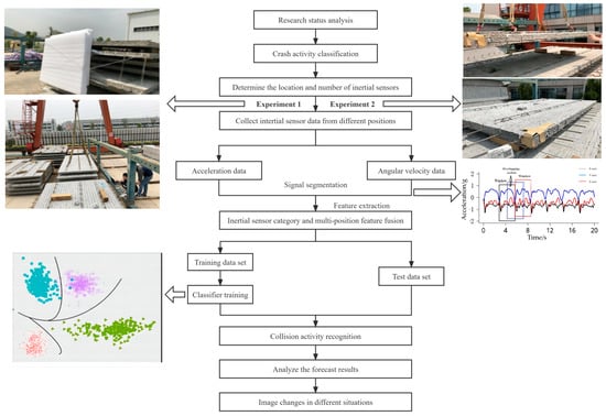
Figure 1.
Research process diagram.
2.1. Data Collection
The experiment was carried out at the production base of the prefabricated component factory of Xiamen Zhixin Building Materials Co., Ltd. (Xiamen, China). A sample of the prefabricated laminated board is shown in Figure 2. After observing the hoisting activities of the prefabricated components by the gantry crane, the hoisting activities were divided into four situations: the stationary hoisting component, the rising of the hoisting component, the travel of the hoisting component, and the descending of the hoisting component. Furthermore, BWT61CL IMUs were used for collecting hoisting activity data. Workers used gantry cranes to carry out hoisting prefabricated laminated boards. The acceleration of the equipment unit was set to ±8 g; the angular velocity used was up to ±2000°/s. In addition, the IMU sensor was fixed on the two opposite corners of the prefabricated laminated board and the hook of the gantry crane with paper tape, as shown in Figure 2 and Figure 3. At the same time, the placement surface of each equipment unit was kept consistent to prevent the experimental results from being affected by the different orientations of the IMU sensor. The inertial sensor data of the construction activity were collected in real-time when the prefabricated laminated board was hoisted.
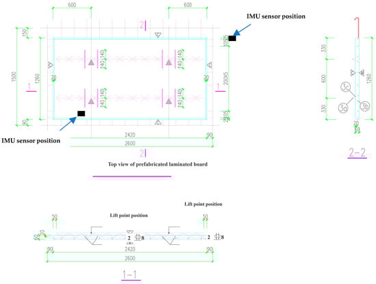
Figure 2.
Schematic of prefabricated laminated board and IMU sensor position.
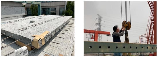
Figure 3.
Schematic diagram of fixed IMU sensor position.
2.2. Data Processing
The IMU inertial sensor is used to collect the hoisting activity data of the fabricated component. The raw data are continuously processed by signal segmentation and feature extraction to generate data that the hoisting activity can identify. In the study, KNN and RF classification algorithms are selected. There is a training sample set in KNN (K-Nearest Neighbor) based on [13], and each piece of data in the training sample set has an active label. In the hoisting activity, the label contains still, up, straight, and down; four categories. Therefore, the relationship between each piece of data in the training sample set and its classification can be known. After inputting the unlabeled test data set, each feature in the new data was compared with the corresponding feature of the data in the sample set, and the most similar data in the sample set was extracted, which is the classification label of the nearest neighbor. Generally speaking, only the first k most similar data in the sample data set are selected. This is the meaning of k in the k-nearest neighbor algorithm, and usually, k is an integer not greater than 20 [14]. Finally, the category with the most occurrences among the k most similar data is selected as the new data category.
RF Random Forest, as a newly emerging and highly flexible machine learning algorithm, has a strong generalization ability and good classification effect [15]; it is a collection method of classification and regression based on a tree model [9], and its basic unit is a decision tree, where each decision tree is a classifier. N trees will have N classification results for an input sample, and random forest integrates all classification voting results; the most votes and the category are designated as the final output. The two classification algorithms are applied to the generation of inertial sensor category configuration models for a single location, two location combinations, and three location combinations. Each classification method’s parameters correspond to the maximum accuracy in the tenfold cross-validation configured by a set of parameters. In k-fold cross-validation, the data in each compromise contain the exact proportions of all activity categories to ensure balance. Finally, the performance results of the inertial sensor category configuration model of a single position, two-position combinations, and three-position combinations are comprehensively analyzed. The optimal set of combinations is selected as the optimal hoisting activity recognition model for this study. In order to better and fairly measure the performance of each classifier model in the research, two standard measures in the field of pattern recognition are used: Accuracy and F-measure:
Among them, true positive (TP): correctly classified as the category of interest; true negative (TN): correctly classified as the category of uninteresting; false positive (FP): incorrectly classified as the category of interest; and false negative (FN): Wrong classification as an uninteresting category.
2.3. Hoisting Activity Recognition Model
Considering the differences in inertial sensor signals at various positions for the same activity, the inertial sensor signals will vary with different positions, so the recognition of complex hoisting activities will also vary with the change in inertial sensor types and position combinations [16]. The feasibility of using IMU acceleration and angular velocity data to classify hoisting activities can establish and evaluate the model under each sensor data at the same time, through the data combination of multiple inertial sensors [7] at different positions and the fusion of acceleration and angular velocity to optimize the recognition model of assembly-type building component hoisting activities. In order to verify the actual application effect of the hoisting activity recognition model, the hoisting activity data collected by the IMU are used as the training data for the model establishment. All the data are segmented using a window size of 1 s, and features are extracted to form a feature vector. The training of the model uses two classification algorithms, KNN and RF.
2.3.1. Analysis of IMU Sensor Results at a Single Location
In order to study the recognition of hoisting activities with various data of inertial sensors at a single location, the recognition performance of hoisting activities under the state of collecting the same activity data at the exact location was analyzed in detail. Table 1, Table 2 and Table 3 are the recognition models of each inertial sensor. The No. 3 inertial sensor and the No. 6 inertial sensor are located at two opposite corners of the prefabricated laminated board. The No. 8 inertial sensor is located on the hook of the gantry crane. A and G represent acceleration and angular velocity in the table, respectively; KNN and RF represent two classification algorithms used for the classifier.

Table 1.
No. 3 sensor hoisting activity recognition model.
Table 2.
No. 6 sensor hoisting activity recognition model.
Table 3.
No. 8 sensor hoisting activity recognition model.
The IMU data collection experiment of hoisting movable inertial sensors was carried out in a controlled outdoor scene. First, the collected data were divided into segments, then the feature extraction algorithms were used to calculate the features of each segment to form a feature vector, and the features of each segment were manually assigned. The vector added the corresponding hoisting activity label, according to the inertial sensor category and position combination for feature vector fusion. The feature vector set was combined with the classification algorithm to generate the hoisting activity recognition model. Finally, the performance of the hoisting activity recognition model was comprehensively evaluated by the model evaluation method. The accuracy formula to evaluate the above model was used, and the results are shown in Table 4.
Table 4.
Accuracy Evaluation of Single Position Hoisting Recognition Model.
2.3.2. Analysis of Results of IMU Sensor Fusion of Two Positions
In order to study the optimization problem of the inertial sensor category and location combination for construction activity recognition, the results of the inertial sensor category configuration model after the combination of two locations were analyzed in detail. Table 5 shows the accuracy results of the two position combinations’ inertial sensor category configuration model under the four classifiers.
Table 5.
Evaluation of the accuracy of the recognition model of two-position fusion inertial sensors.
From Table 5, it can be seen that the acceleration and angular velocity fusion of the No. 6 inertial sensors and the activity recognition model of the No. 8 inertial sensor acceleration have the highest accuracy, which is 93.05. In two-position combinations, the inertial sensor type and position combination model has the best performance. In order to specifically analyze the recognition performance of various lifting activities of the two-position fusion inertial sensor recognition models, research needs to continue to use the F-measure value to quantify the recognition ability of each type of lifting activity, as shown in Table 6. A higher F-measure value indicates this higher activity accuracy [17].
Table 6.
The F-measure value of the best recognition model of two-position fusion inertial sensors—Classified lifting activities.
It can be seen from Table 6 that the position combination of the No. 6 inertial sensor and the No. 8 inertial sensor has the best effect in the recognition and classification of hoisting activities. The acceleration and angular velocity fusion of the No. 6 inertial sensor and the combination of acceleration of the No. 8 inertial sensor can recognize ascending activities by 100%. In addition, the combination of the acceleration of the No. 6 inertial sensor and the acceleration and angular velocity fusion of the No. 8 inertial sensor has good recognition performance for various hoisting activities, and its F-measure value has reached more than 80%.
2.3.3. Analysis of IMU Sensor Results Fused in Three Positions
In evaluating the recognition performance of the inertial sensor recognition model of the combination of three positions, inertial sensors are installed at the two opposite corners of the assembled component and the gantry crane hook. Each location will generate three data categories of A, G, and A + G data, and each combination model is based on two classification algorithms. Then there are 54 types of inertial sensor configurations for the combination of three locations, as shown in Table 7.
Table 7.
Accuracy Evaluation of Three-Position Fusion Inertial Sensor Recognition Model.
It can be seen from Table 7 that the three-position fusion inertial sensors are based on the KNN classification algorithm and the RF classification algorithm. The best two hoisting activity recognition models are the combination of acceleration and angular velocity fusion data of the No. 3 inertial sensor, acceleration, and angular velocity fusion data of the No. 6 inertial sensor, and acceleration of the No. 8 inertial sensor; and the combination of acceleration and angular velocity fusion data of the No. 3 inertial sensor, acceleration of the No. 6 inertial sensor, and acceleration of the No. 8 inertial sensor. Its accuracy is 93.03 and 93.16, respectively. Further, the recognition ability of each activity through the F-measure value is quantified, as shown in Table 8; a higher F-measure value means that the classification of hoisting activities is highly recognized. Based on the accurate evaluation of the above three-position fusion inertial sensor recognition models, we conducted an F-measurement value analysis and evaluation of the two groups of optimal accuracy three-position fusion inertial sensor hoisting activity recognition models.
Table 8.
F-measure value of the best recognition model of three-position fusion inertial sensors—Classified lifting activities.
Table 8 shows that the first combination has better recognition performance for various lifting activities, and its F-measure value is 88.51%. Based on the above analysis, the accuracy of 54 groups of the three-position fusion inertial sensor hoisting activity recognition model is evaluated, the combination of the acceleration and angular velocity fusion data of the No. 3 inertial sensor, the acceleration and angular velocity fusion data of the No. 6 inertial sensors, and the acceleration of the No. 8 inertial sensor is the optimal model among the recognition models of the three-position fusion inertial sensors. The acceleration and angular velocity fusion data at the two diagonals of the prefabricated laminated board and the combination of acceleration at the gantry crane hook are the best hoisting activity recognition effect.
3. Collision Analysis of Assembly Component Hoisting
3.1. Collision Activity Classification
In construction activities, collisions are divided into three situations: direct collision, sudden stop, and detour in a particular space from obstacles. The specific classification is shown in Table 9.
Table 9.
Collision classification.
3.2. Image Analysis for Collision Classification
Analyze the images of three types of situations: direct collision, sudden stop, and detour to understand collision activities’ characteristics further and classify collision activities more accurately. According to the best recognition model, the sensors are placed on the diagonal of the component and above the hook and renamed as No. 3, No. 5, and No. 7. The three pictures in Figure 4 are the acceleration images of the three sensors within 10 s of the collision. At this time, the strength and number of collisions can be judged according to the magnitude and peak value of the acceleration image curve fluctuations. Therefore, it is possible to intuitively express the current situation of the component without introducing the angular velocity image.
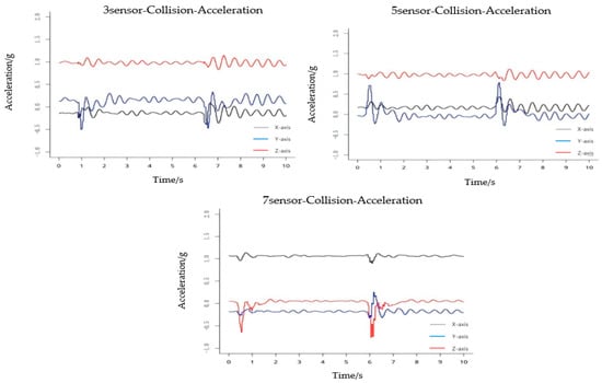
Figure 4.
Acceleration graph during a collision.
It can be seen from Figure 5 that the acceleration during an emergency stop fluctuates continuously. It can only be seen that the curve fluctuates wildly during a specific period. However, looking at the acceleration image of a specific sensor alone, it is found that the peaks and valleys do not appear simultaneously. Therefore, the acceleration image of a single sensor in the case of an emergency stop cannot accurately determine when the component suddenly stops. It is necessary to introduce the angular velocity image of the sudden stop for auxiliary analysis.
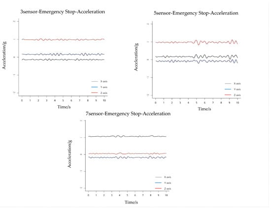
Figure 5.
Acceleration graph at the sudden stop.
The image fluctuation of the angular velocity is more evident than the acceleration, as shown in Figure 6 and Figure 7. According to the image of the angular velocity, it can be seen that the fluctuation of the angular velocity suddenly increases during the 4~5 s period, especially in the No. 5 and No. 7 sensors. Even a peak appears in the image, indicating that a sudden stop behavior occurs in this interval. The violent fluctuations in the subsequent time are due to the violent shaking of the component caused by inertia. During the detouring process, the crane operator can always maintain a constant speed when hoisting. The acceleration is always maintained at zero at a constant speed to fluctuate within a small range of negligible values. Therefore, the acceleration image is of little significance in distinguishing orbiting activities, and the angular velocity image is selected for analysis.
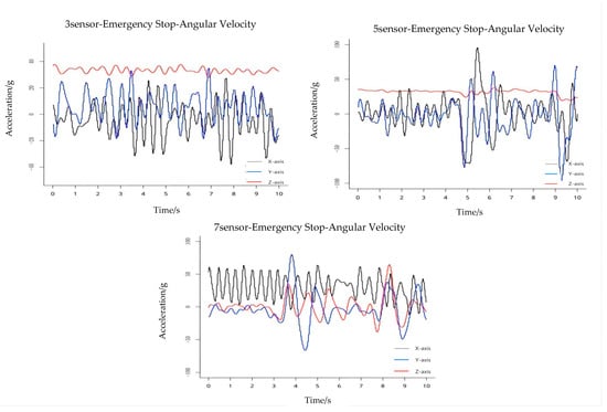
Figure 6.
Angular velocity graph at the sudden stop.
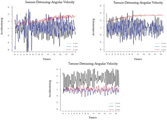
Figure 7.
Angular velocity graph during orbiting.
When the image is in the fourth second, the angular velocity of the three sensors all show an increasing trend, indicating that the orbiting activity begins, which leads to the increase in the rotation angle of the component and the increase in shaking. At the 17th second, the angular velocity change image is similar to the previous 3 s, and it can be concluded that the orbiting activity ends at this time. Compared with the first two activities, the detour to distinguish a single image due to its long duration is more challenging. However, because the acceleration of the orbiting activity is almost zero, the combination of acceleration and angular velocity can quickly determine that the activity is orbiting. In summary, through image analysis, it can be considered that the differences between the three activities are:
(1) In the event of a collision, both the acceleration and the angular velocity will form a complete wave crest and trough within 1 s. This is due to the short duration of the accident at the collision and the great harm that occurred. Compared with the other two activities, the collision can be distinguished based on whether there is a sudden change in the image and not continuous.
(2) In the case of a sudden stop, it is necessary to combine the acceleration image and the angular velocity image to determine the emergency stop time. Since the fluctuation of sensor three is not apparent, it is not considered. The most significant feature of the sudden stop of the image is that there will be continuous and decreasing fluctuations in the subsequent time of the sudden fluctuation, and the actual situation will be restored after a while.
(3) The activity lasts the longest in the detour situation, so the analysis time is also the longest. The most obvious thing about the orbiting activity is that there is almost no fluctuation in the acceleration image, and the orbiting activity has no effect on its acceleration.
In the angular velocity image, it can be found that its image is a bit similar to the emergency stop situation because there will be shaking or rotation during the detour and emergency stop, and the angular velocity changes significantly. So, the most straightforward point to distinguish between these two activities is to observe the changes in the acceleration image. Finally, the study summarized the standardized operation process of using the IMU to detect the hoisting collision of fabricated building components, as shown in Figure 8.
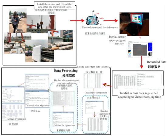
Figure 8.
IMU standard operation process for detecting the collision of prefabricated building components.
4. Discussion
Existing studies have paid little attention to the collision of prefabricated component lifting activities; Refs. [9,10,11] provided great theoretical ideas and effectively improved the accuracy of collision detection for prefabricated component lifting activities. However, research processes were mainly based on simulations and did not consider real-time collision detection. As a mainstream tool for monitoring object motion, the IMU can measure motion without any spatial constraints [18]. Even though [19] combined Internet of Things (IoT) technology and IMU to optimize the real-time prefabricated component lifting activity recognition, the study ignored the lifting activity collision situation. Based on three situations of collision activities, the IMU and KNN and RF algorithms were used for establishing the hoisting activity recognition model in this study, which significantly improved the real-time detection with high accuracy. Under the three-location data fusion, the acceleration and angular velocity fusion data at the two diagonals of the prefabricated laminated board, and the combination of acceleration at the gantry crane hook obtained the best hoisting activity recognition effect, thereby providing reliable support for prefabricated component lifting collision activity detection. The acceleration and angular velocity images collected by the IMU were used for summarizing the image features of different collision situations to determine the collision situation: (1) the direct collision can be distinguished based on whether there is a sudden change in the image; (2) there will be continuous and decreasing fluctuations in the acceleration and angular velocity images of a sudden stop; and (3) almost no fluctuation acceleration images and fluctuating angular velocities can be used for direct recognition of detour activities.
In this study, the data were collected under a normal operating environment. The lifting process of prefabricated components may be influenced by wind factors and jitter of lifting activities, resulting in small fluctuations of acceleration images and angular velocities. The small fluctuations hardly influenced the judgment of collision situations, yet higher demands were placed on the robustness of the hoisting activity recognition model. As a limitation, the influence of external factors was not fully considered in this study. Meanwhile, although the study provided technical support for the safety of prefabricated components lifting, it did not develop an intelligent system, which is a direction worth further exploration.
5. Conclusions
In this study, a hoisting activity recognition model was constructed based on the fusion of the IMU and KNN and RF algorithms. The optimal position combination of multiple inertial sensors was obtained. Based on the optimal position combination, the collision analysis of assembled components was carried out. First of all, the prefabricated laminated slabs that are common on the prefabricated building component factory site were selected as the object of this study, and the classification of hoisting activities and the classification of collision types were determined. The classification included several types of activities with high repetitiveness in hoisting activities. Secondly, the IMU inertial sensors in multiple positions were combined. Based on the IMU and algorithm fusion, the sensor is placed on the two diagonals of the prefabricated laminated board and the hook of the gantry crane. When specific hoisting activities occur in these places, the motion amplitude is the largest, and the sensor data volume changes significantly. It is concluded that the optimal combination of the inertial sensor category and position is the fusion data of acceleration and angular velocity at two diagonals, and the combination of acceleration at the hook of the gantry crane has the best hoisting activity recognition effect. The accuracy of the optimal model is 93.03%.
Finally, a collision study was carried out based on the hoisting activity recognition model. The data collected by the inertial sensors placed on the component were imaged to predict the possible collision behavior and determine whether the component will appear under the component route collision situations to avoid such situations. According to our systematic research and discussion of hoisting activity recognition and collision behavior, a reasonable basis and ideas for solving the collision of hoisting in prefabricated buildings have been provided, which will help inertial sensors in construction to provide help for construction automation. In addition, further optimization of model accuracy under the influence of more external factors (e.g., wind), as well as the combination of different types of sensors and IoT technologies to improve the real-time collision recognition of prefabricated buildings hoisting will be the direction of further exploration in the future.
Author Contributions
Conceptualization, C.W., L.Y., M.A.K. and K.N.A.; methodology, C.W., L.Y., M.W. and J.B.H.Y.; software, C.W., L.Y., M.W. and J.B.H.Y.; validation, C.W., L.Y., M.W., K.N.A. and J.B.H.Y.; formal analysis, C.W., L.Y., M.W. and J.B.H.Y.; investigation C.W., L.Y. and M.W.; resources, C.W., L.Y. and M.W.; data curation, C.W., L.Y., M.W., J.B.H.Y. and M.A.K.; writing—original draft preparation, C.W., L.Y. and M.W.; writing—review and editing, C.W., M.A.K., K.N.A. and J.B.H.Y.; visualization, C.W., L.Y., M.W. and J.B.H.Y.; supervision, C.W., M.A.K. and K.N.A.; project administration, C.W., L.Y., M.W. and M.A.K.; funding acquisition, C.W., L.Y., M.W. and K.N.A. All authors have read and agreed to the published version of the manuscript.
Funding
This research was funded by Fujian Province Science and Technology Department of China (grant number 2021I0014); the Quanzhou Tongjiang Scholar Special Fund for financial support through grant number (600005-Z17X0234); Huaqiao University through grant number (17BS201), and Universiti Teknologi Malaysia (UTM) Research Grant Vot No: (05E79).
Institutional Review Board Statement
Not applicable.
Informed Consent Statement
Not applicable.
Data Availability Statement
The data sets during and/or analyzed during the current study are available from the corresponding author on reasonable request.
Acknowledgments
The authors are grateful to the research grants awarded by the Fujian Province Science and Technology Department of China (grant number 2021I0014); the Quanzhou Tongjiang Scholar Special Fund for financial support through grant number (600005-Z17X0234); Huaqiao University through grant number (17BS201), and Universiti Teknologi Malaysia (UTM) Research Grant Vot No: (05E79).
Conflicts of Interest
The authors declare no conflict of interest.
References
- Yuchi, W.; Ronghua, C.; Qi, L.; Tao, C.; Chao, Z. Overview and prospects of the development of prefabricated buildings. Introd. Sci. Technol. 2017, 14, 162–192. [Google Scholar] [CrossRef]
- Hao, W. The current situation and future development of prefabricated buildings. Jiangxi Build. Mater. 2016, 10, 45. [Google Scholar] [CrossRef]
- Fei, W. Research on Anti-collision Technology of Crane Hoisting. Chang. Univ. 2014. [Google Scholar] [CrossRef]
- Inman, V.T.; Eberhart, H.D. The Major Determinants in Normal and Pathological Gait. J. Bone Jt. Surg. 1953, 35, 543–558. Available online: https://journals.lww.com/jbjsjournal/Abstract/1953/35030/THE_MAJOR_DETERMINANTS_IN_NORMAL_AND_PATHOLOGICAL.3.aspx (accessed on 19 June 2021).
- Morris, J.R.W. Accelerometry—A technique for the measurement of human body movements. J. Biomech. 1973, 6, 729–736. [Google Scholar] [CrossRef]
- Karantonis, D.M.; Narayanan, M.R.; Mathie, M.; Lovell, N.H.; Celler, B.G. Implementation of a Real-Time Human Movement Classifier Using a Triaxial Accelerometer for Ambulatory Monitoring. IEEE Trans. Inf. Technol. Biomed. 2006, 10, 156–167. [Google Scholar] [CrossRef] [PubMed]
- Mathie, M.J.; Celler, B.G.; Lovell, N.H.; Coster, A. Classification of basic daily movements using a triaxial accelerometer. Med. Biol. Eng. Comput. 2004, 42, 679–687. [Google Scholar] [CrossRef] [PubMed]
- Mancini, M.; Chiari, L.; Holmstrom, L.; Salarian, A.; Horak, F.B. Validity and reliability of an IMU-based method to detect APAs prior to gait initiation. Gait Posture 2016, 43, 125–131. [Google Scholar] [CrossRef] [Green Version]
- Lyons, G.M.; Culhane, K.M.; Hilton, D.; Grace, P.A.; Lyons, D. A description of an accelerometer-based mobility monitoring technique. Med. Eng. Phys. 2005, 27, 497–504. [Google Scholar] [CrossRef]
- Hou, X.; Li, C. Research on Collision Detection for Virtual Hoisting Construction Scene. J. Syst. Simul. 2014, 26, 76–84. [Google Scholar] [CrossRef]
- Fan, Q.; Ren, L.; Zeng, Y.; Guo, J.; Zhang, Q. Crane hoisting collision detection method based on plane projection. Lift. Trans. Mach. 2018, 13, 150–154. [Google Scholar] [CrossRef]
- Qiu, S.; Wang, Z.; Zhao, H.; Qin, K.; Li, Z.; Hu, H. Inertial/magnetic sensors based pedestrian dead reckoning by means of multi-sensor fusion. Inf. Fusion 2018, 39, 108–119. [Google Scholar] [CrossRef] [Green Version]
- Zago, M.; Sforza, C.; Pacifici, I.; Cimolin, V.; Camerota, F.; Celletti, C.; Condoluci, C.; De Pandis, M.F.; Galli, M. Gait evaluation using inertial measurement units in subjects with Parkinson’s disease. J. Electromyogr. Kinesiol. 2018, 42, 44–48. [Google Scholar] [CrossRef] [PubMed]
- Zhang, C.; Durgan, S.D.; Lagomasino, D. Modeling risk of mangroves to tropical cyclones: A case study of Hurricane Irma. Estuar. Coast. Shelf Sci. 2019, 224, 108–116. [Google Scholar] [CrossRef]
- Peng, Y.; Kondo, N.; Fujiura, T.; Suzuki, T.; Wulandari; Yoshioka, H.; Itoyama, E. Classification of multiple cattle behavior patterns using a recurrent neural network with long short-term memory and inertial measurement units. Comput. Electron. Agric. 2019, 157, 247–253. [Google Scholar] [CrossRef]
- Tanigawa, A.; Morino, S.; Aoyama, T.; Takahashi, M. Gait analysis of pregnant patients with lumbopelvic pain using inertial sensor. Gait Posture 2018, 65, 176–181. [Google Scholar] [CrossRef]
- Mathie, M.J.; Coster, A.; Lovell, N.H.; Celler, B.G. Detection of daily physical activities using a triaxial accelerometer. Med. Biol. Eng. Comput. 2003, 41, 296–301. [Google Scholar] [CrossRef]
- Punchihewa, N.G.; Yamako, G.; Fukao, Y.; Chosa, E. Identification of key events in baseball hitting using inertial measurement units. J. Biomech. 2019, 87, 157–160. [Google Scholar] [CrossRef] [PubMed]
- Zhao, Y.; Cao, C.; Liu, Z.; Mu, E. Intelligent Control Method of Hoisting Prefabricated Components Based on Internet-of-Things. Sensors 2021, 21, 980. [Google Scholar] [CrossRef] [PubMed]
Publisher’s Note: MDPI stays neutral with regard to jurisdictional claims in published maps and institutional affiliations. |
© 2022 by the authors. Licensee MDPI, Basel, Switzerland. This article is an open access article distributed under the terms and conditions of the Creative Commons Attribution (CC BY) license (https://creativecommons.org/licenses/by/4.0/).