Article

Experimental and Numerical Analyses of Thermal Storage Tile-Bricks for Efficient Thermal Management of Buildings

1
School of Chemical Engineering, Zhengzhou University, Zhengzhou 450001, China
2
School of Ecology and Environment, Zhengzhou University, Zhengzhou 450001, China
3
National Centre of Research & Popularization on Calcium, Magnesium, Phosphate and Compound Fertilizer Technology, Zhengzhou 450001, China
4
Institute of Refrigeration and Cryogenics, Shanghai Jiao Tong University, Shanghai 200240, China
5
Department of Chemical, Polymer and Composite Materials Engineering, University of Engineering and Technology, New Campus, Lahore 39021, Pakistan
*
Author to whom correspondence should be addressed.
Buildings 2021, 11(8), 357; https://doi.org/10.3390/buildings11080357
Submission received: 26 June 2021 / Revised: 1 August 2021 / Accepted: 13 August 2021 / Published: 17 August 2021
(This article belongs to the Section Building Materials, and Repair & Renovation)

Abstract

:
Due to the tremendous increase in the population and emerging energy crisis, the surging demand for the thermal management of buildings has become essential. Thermal management of buildings is of high importance for maintaining optimum thermal comfort and controlling the drastic environmental impacts. To avoid high energy consumption strategies and continuous operation such as active air heaters and air conditioners, passive strategies driven by phase change material-based thermal storage are expected to leverage the energy challenges. This work attempts to present the form-stabilized thermal storage tile-bricks (TSTBs) that are fabricated by a combination of octadecane, phosphogypsum, kaolin clay and cement. The optimal percent contents of each entity were found with respect to the design criterion of form-stability and effective temperature control capacity. Two TSTBs with a thickness of 10 mm and 15 mm were constructed, which are then applied on ordinary clay bricks to build a prototype wall. The optimal TSTBs are experimentally and numerically evaluated by subjecting them to transient thermal performance analysis, providing longer temperature retardation (~3000 s) compared with ordinary clay bricks (~400 s). It is thus implied that TSTBs can provide a viable solution against energy mismanagement by inhibiting the heating in summer and reserving the cold in winter.

1. Introduction

The 2020 Global Status Report for Buildings and Construction [1] highlights the importance of the building thermal regulation by the green materials and endorsed the need to find alternative energy sources. The building sector is the most energy-consuming sector globally, as it consumes 35% of the total power generated and emits CO2 at ever-higher levels, i.e., ~10 GT which is equivalent to one-third of the total emissions of the world. This means that the building sector is moving away from the Paris Agreement of maintaining the global mean temperature rise below 2 °C. One of the main reasons behind such alarming environmental threats is that fossil fuels are the main source of energy generation which cause pollution and global warming [2] and the conventional means of thermal regulation of building such as heaters, air conditioners and HVAC systems are contributing in the greenhouse effects [3]. Renewable energy, e.g., solar, wind, biomass and geothermal, etc. could be viable options for less of a dependency on fossil fuels. However, renewable-based energy has very serious limitations, e.g., location and season dependence and therefore could not smoothly fulfill the energy demand. Therefore, rendering the buildings sustainable space heating, cooling and especially in electrical energy consumption associated with minimum greenhouse effect [4] is indispensable, whereby coupling the electrical energy with thermal energy is deemed to be the viable option [5]. Thermal energy storage can be achieved by three primary modes [6]: thermochemical storage; sensible heat storage systems; (SHSS) and latent heat storage systems (LHSS). LHSS is more advance and is preferred over SHSS and thermochemical, as it has more energy storage density, fewer temperature fluctuations unlike SHSS, has no design complications unlike the other two modes and is relatively more economical than the other two modes [7]. The materials which have the intrinsic ability to undergo latent heat storage are called phase-change materials [8] and this mode of thermal energy storage is considered safer, as there is no risk of greenhouse gas emissions unlike conventional HVAC systems in buildings [9]. That is why PCMs are considered as green materials [10], and along with many other applications such as in textile [11], food [12] and batteries [13], they are catching more and more attention in building thermal regulations in an endeavor to establish a green atmosphere in residential buildings. The operation of PCMs is mainly activated by the external stimulus, such as heat and/or light, based on which latent heat zone [14] is achieved with (almost) isothermal performance. It demonstrates that the PCM-based thermal energy is indeed the passive thermal management [15], i.e., the human efforts and the temperature controllers are not required for thermal regulation of buildings. However, despite much work on PCM-driven thermal management of buildings [16], the challenges posed by the PCM still exist, e.g., encompassing liquid drainage threats [17], compatibility with building materials (cement, sand, or their mixtures) [18] and temperature mismatch necessary for the human comfort zone [19]. The criterion of avoiding the temperature mismatch is dependent on the temperature of the human comfort zone [20]. Thus, the fundamental design standard of the PCM-driven thermal management system is to precisely select the PCM [21] with the melting temperatures within 18 to 28 °C as suggested by Du et al., [20] corresponding to the human comfort zone. Other design standards include the features of the PCM [22], such as environmental-friendly, thermally durable, chemically stable and effective insulation (low thermal conductivity). Opposed to other thermal management applications where high thermal conductivity of PCM is required [23], the low thermal conductivity of PCM is necessary for the thermal management of buildings [24]. This is due to the difference in working principles, i.e., a thermally managed building is expected to maintain its temperature, which means that the heat from ambient should not travel inside the building during the summer season, and heat should not travel from the building to ambient during the winter season. Normally, PCMs have low thermal conductivity [25] whether they are organics, inorganics or eutectics [26]. Organic PCMs include paraffin waxes, fatty acids, polyalcohols and polymers, while inorganics include salt hydrates, water and metals [27]. Depending on the fundamental design standard of the temperature range for thermal management of buildings, the melting temperatures of most of the fatty acids, polyalcohols, polymers, salt hydrates and metals are unfavorable; however, their eutectics can be fabricated to meet the criterion. Among many paraffin waxes, hexadecane, heptadecane and octadecane have melting temperatures of 18 to 19 °C, 20 to 22 °C and 24 to 28 °C [28,29], respectively, which are declared to be the most suitable ranges for the design criterion. However, hexadecane and heptadecane exist in the liquid phase and their melting temperatures lie at the lower end of the design temperature, leaving behind the octadecane with a melting temperature lying almost in the middle of the design temperature.
After the successful selection of the PCMs, the corresponding challenge of liquid drainage and compatibility needs attention. In the recent decade, attempts were conducted aiming at controlling the liquid drainage by fabricating the thermal composites with help of thermal reinforcements [30,31]. There are many kinds of thermal reinforcements, encompassing organic encapsulations (e.g., high-density polyethylene) [32] and inorganic sorbents (e.g., expanded graphite, copper foam, and kaolin, etc.) [9,33], and their selection is also dependent on the target applications. Low thermal conductivity is required to be maintained for the thermal management of buildings. Therefore, thermal reinforcement is supposed to have low thermal conductivity as well as high sorption capacity based on which effective form-stabilized PCM thermal composites can be fabricated. Organic encapsulation of the PCM is a viable option [34], however, the fabrication process is relatively complex compared to organic sorption, as in them, only physical mixing takes place [35]. Based on the low thermal conductivity and effective form-stabilizing capability, the organic sorbents [36], including the styrene, butadiene, expanded perlite, diatomite, vermiculite and kaolin clay, are therefore the most suitable for PCM thermal composites intended for thermal management of buildings.
The compatibility of the PCM thermal composite with building material [18] is the most significant in the overall design since the inherent properties of all the ingredients need to be satisfied. The building materials majorly include bricks, cement (which is itself a mixture composed of a wide variety of materials), sand, etc., providing various options where the PCM thermal composite can be applied. In recent decades, the PCM-based building wallboards were developed [37], involving the incorporation of PCM with the gypsum, concrete, or cement [38] and other construction materials [39]. For example, Lu et al., [40] introduced form-stabilized PCM composite (70 wt.% of paraffin wax with a melting temperature of ~16 to 22 °C, 5 wt.% of high-density polyethylene and 15 wt.% of expanded graphite) in the room wall and evaluated the thermal performance, finding the effective results with the composite PCM-wall. Nghana et al., [41] used a BioPCM with a melting temperature of 23 °C in the walls of twin buildings to check the thermal performance of PCM wallboards and the thermal comfort in the buildings. A reduction in temperature fluctuation of 1.4 °C in the indoor air temperature and 2.7 °C in the internal wall temperature was observed. Cabeza et al., [42] employed a commercial-grade microencapsulated PCM called Micronal PCM (melting point of 26 °C and latent heat of 110 Jg−1) in the concrete board and compared the PCM-enriched concrete board with the conventional concrete and concluded that the PCM-enriched concrete has efficient thermal performance during summer. Ling et al., [43] did experimental and numerical studies on a greenhouse compartment for 61 days which were sunny and cloudy days, observing the indoor and outdoor air temperature with the help of GH-20 PCM (melting temperature of ~7 to 26 °C) wallboard. The significant reductions in the indoor air temperature and less outdoor air temperature fluctuations were demonstrated with the PCM wallboard than that of the wallboard without PCM. Zhang et al., [44] incorporated octadecane/expanded graphite into the cement mortar, finding the reduction in the indoor air temperature that resulted in the decreased energy consumption of the building. Islam et al., [45] used sodium sulfate decahydrate (with a melting point of 32.4 °C) as PCM and incorporated it with conventional building materials, e.g., sand, cement, and aggregates of bricks and built a prototype wall for incorporating PCM in a room and carried out experiments on hot sunny days. On comparing the prototype wall with and without the PCM room, overall a reduction of 3 °C in average temperature was observed. Hekimoğlu et al. [46] used fly ash, lauric acid and myristic acid eutectic mixture composites (FSC), with a melting point of 31.1 °C and latent heat of 45.3 J/g, incorporated it into standard cement mortar. During their work, it was observed that FSC and the cement mortar have good compatibility with each other and FSC showed better thermal performance than the standard cement mortar. In summary, the right melting temperature of the PCM is important compared with the mass percent of PCM in the building materials, as maintaining the mechanical strength of buildings with PCM is a challenging task. Thus, finding the optimum percentage of PCM in building applications is also declared to be the vital design parameter.
In this paper, form-stabilized thermal storage tile-bricks (TSTBs) are presented in different thicknesses of 10 and 15 mm. The TSTBs are composed of phosphogypsum (PG), octadecane (OD), Kaolin clay (KC) and cement (CM) with the main functions of strength improver, thermal storage, form-stabilizer, and intermediate binder, respectively. PG is an industrial waste of phosphoric acid and about 4.8–5 tons of the PG are produced during the production of one ton of phosphoric acid [47]. PG is still at a relatively early stage in terms of finding its vital application on a larger scale. PG has been employed with higher wt.% in all the thermal composites of TSTBs, as it is supposed to be an important replacement material instead of natural gypsum, resulting in sustainable applications in the construction and building sector [48]. The thermal composites of TSTBs were prepared by adopting the thermal absorption-stirring method with varying mass percent of each ingredient until the optimal conditions are ensured, consisting of the effective form-stability and temperature-control capacity. The form-stability of thermal composites was confirmed by a filter paper-based thermal annealing test, and temperature-control capacity is assessed via a transient thermal analysis. After finding the optimal thermal composite, the TSTBs were successfully manufactured via iron mold and tested with the help of successive thermal storage/release analysis, as well as by means of hydro-stability analysis.

2. Materials and Methods

2.1. Materials

Octadecane (OD) was purchased from Shanghai Macklin Biochemical Limited, Shanghai, China and the remaining additives, i.e., Kaolin clay (KC), phospho-gypsum (PG) and cement (CM) were purchased from the local vendors in Zhengzhou, Henan, China. To remove the larger and uneven flakes, 0.08 mm mesh was used to strain the PG, KC and CM powders in the laboratory because, for example, different particle sizes of kaolin clay have a different impact on the thermal conductivity. Ordinary bricks for building the prototype wall were purchased from local vendors in Zhengzhou, Henan, China to build a prototype wall of a room in the lab. A high-temperature lamp of 220 V–160 W was purchased from Zhuguang Bell Lighting Appliance Factory, Shenzhen, China to simulate the sunlight. Two thermal couple needles are attached with a data acquisition system (SH-X) to record the temperature during the thermal transient analysis as shown in Figure 1.

2.2. Preparation of Thermal Composites and Characterization

PG powder and KC were kept in the electric oven for 12 h at 120 °C for removing the moisture content. OD was melted on the electric heater at 60 °C followed by the addition of dried PG/KC while stirring for 5 min, and then constant heating at 60 °C was maintained for 1 h. Afterward, the thermal composite is cooled by shutting down the heater. During the cooling process, thermal composite is constantly stirred to avoid cluster-formation and achieve a uniform powdery form. By following the same steps, three different thermal composites were prepared including OD/PG, OD/PG/KC and OD/PG/KC/CM with compositions as listed in Table 1.
Thermal composites were experimentally optimized through filter-based thermal annealing tests and transient thermal analysis. In the filter-based thermal annealing method, the filter paper was set on the heater, furthermore, 10 g of the thermal composite was uniformly spread on the filter paper. The heat is maintained for 1 h by setting heater temperature at 50 °C, which is sufficiently higher than the melting temperature of OD. Transient thermal analysis was conducted with help of a custom-built cuboid composite containment unit of 40 mm × 40 mm × 50 mm (W × L × H), made up with aluminum, see Figure 1, which is capable of containing around 40 g of thermal composite. After tightly filling the thermal composite in the containment unit via hand-compression, a T-type thermocouple was inserted in the middle (from all directions). The filled containment unit was set on the heater with a constant temperature of 50 °C, and the temperature–time data were recorded through a data acquisition system (SH-X). In addition, morphological inspection via scanning electron microscopy (ZEISS SE2), specific heat, latent heat and melting temperature measurement via differential scanning calorimetry (NETZSCH DSC 214) and thermal conductivity measurement via transient plane source method (Hot Disk TPS2500S) were included.

2.3. Preparation of TSTBs

TSTBs are manufactured by using an iron mold of 160 mm × 85 mm × 40 mm. The TSTBs were manufactured through an iron mold in two steps: (i) the mold is set at the constant temperature of 50 °C in which the fully-heated optimal thermal composite (TC5) is uniformly layered with sufficient hand-compression; (ii) after 1 h, the heater is shut down so that the slow cooling is ensured, followed by separating the TSTBs from the mold after 1.5 h. Following the same method, two TSTBs varying in thickness of 10 mm and 15 mm were manufactured, labeling as TSTB10 and TSTB15, respectively. Later, the TSTBs were practically demonstrated through thermal storage/release analysis by applying them onto the prototype wall (both inside and outside for summer and winter season realization) with help of a thin layer of cement/water paste. The prototype wall was constructed by using ordinary bricks (total 8) with dimensions of 190 mm × 90 mm × 45 mm.

3. Results and Discussion

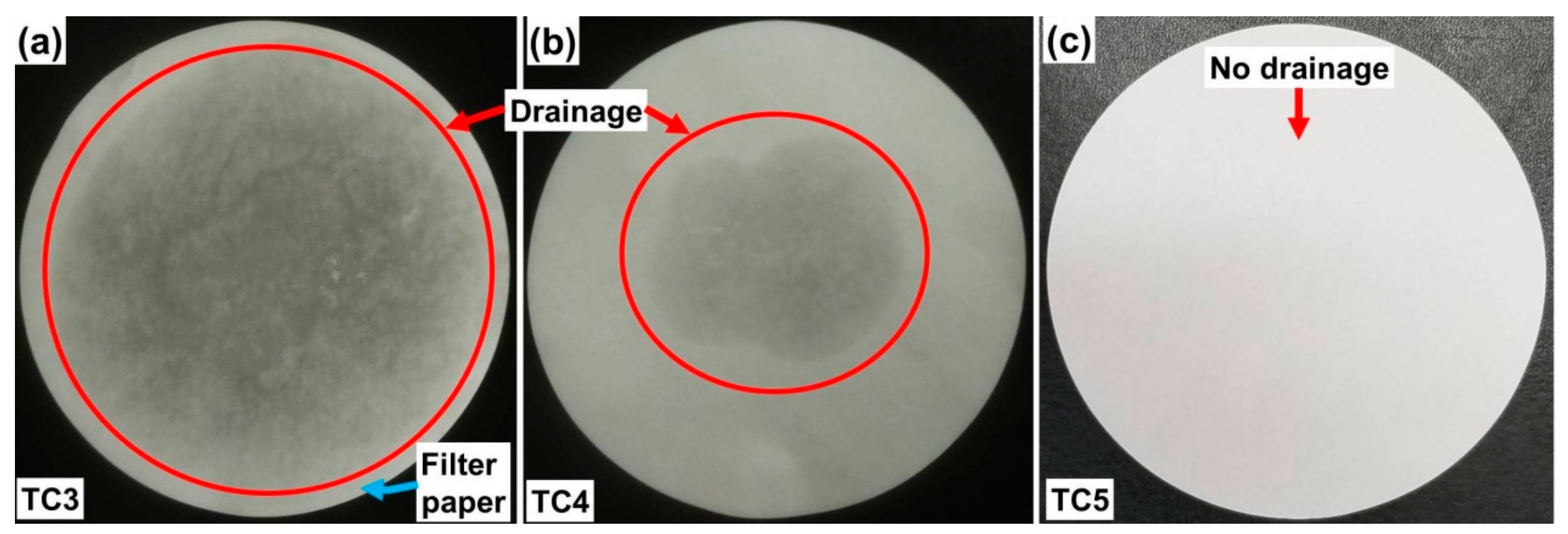
3.1. Form-Stability and Temperature-Control Capacity

The form-stability and temperature-control capacity of thermal composites were set as the design criteria. The form-stability is defined as the state in which the liquid drainage from the phase change thermal composite is negligibly small or eventually stopped. This is the key design parameter for building applications, where a mechanical enclosure (another option to control the drainage) is unfavorable to hold thermal composites. Therefore, thermal composites need to sustain the shape during the melting process in which liquid drainage can lead to PCM depletion, rendering the thermal management non-self-sufficient. The form-stability of as-prepared thermal composites was analyzed via a filter paper-based thermal annealing test. Thermal composites (TC1 and TC2 in Table 1) were prepared to consist of PG and OD with varying wt.%; however, the PG, both in high (95%) or low weight percent (80%), failed to contain the OD during its melting, signifying that PG alone is not a form-stabilizer. When inspected in the SEM (see Figure A1 in Appendix A), the morphology of PG appeared to be non-porous consisting of slab-like flakes even after grinding before the SEM analysis. However, finding the most effective form-stabilizer is complicated based on the target applications. For example, the form-stabilizer for building applications should not necessarily be a thermal conductivity enhancer, as the purpose in building thermal management is to control the heat flow by reserving it either inside or outside the rooms, during winter and summer, respectively. Based on this design objective, the KC (Kaolin clay) was employed as a form-stabilizer with different wt.%, listed in Table 1. When KC is 5% in thermal composite (TC3 in Table 1), form-stability cannot be achieved, as during the melting process considerable drainage of OD occurred, encircled in red, see Figure 2a. When KC is increased by 15% (TC4 in Table 1), the probability of achieving the form-stability is also increased since almost two-fold less drainage takes place, as depicted by red-circle in Figure 2b. Likewise, with 30% K (TC5 in Table 1), the form-stability is ensured because negligible (or no) drainage occurs, as demonstrated in Figure 2c. Therefore, it is concluded that there is a maximum extent of form-stabilizer that can effectively control the drainage and such a thermal composite is called the optimal composite based on the form-stability criterion (TC5 in this study). The possible reason for the achieved form-stability is the porous and fluffy property of KC wherein the melted PCM is sufficiently infused. Furthermore, no slab-like structures of PG were observed in TC5 depicting great matching compatibility of all the ingredients that are tightly-packed via inter-connected clustered units, which can be seen in SEM images shown in Figure A1 (Appendix A). This tight-packing is highly supportive in developing the TSTBs which is discussed in the next section.
To meet the second design criterion of temperature-control capacity, sole PG, sole cement and other phase change thermal composites are subjected to transient thermal analysis. The results are depicted in Figure 3 and Figure A2 (Appendix A).
When PG and CM are employed, the fast-rise in temperature profile can be seen which is ascribed to the sensible mode of heat storage. In other words, there is no isothermal zone that can help provide temperature-control capacity in sole PG and CM due to which a considerable amount of electrical and thermal energy is expected to be lost both in summer and winter. Electrical energy is required for the continuous operation of the air conditioners and heaters, leading to unsustainability in the environment if they are shut down. Therefore, passive thermal management of the building materials is indispensable so that energy relief can be delivered. With phase change thermal composites, the fast-rise in temperature is impeded, as shown in Figure 2; however, the optimal quantity of each ingredient is essential. By comparing the temperature profiles of sole PG, CM and TC5, a prominent isothermal zone appears that tends to last for around 1500 s in the case of TC5. The total time to reach the discomfort temperature zone for TC5 is also prolonged by more than 3000 s compared with 400 s of sole PG and CM. The reasons are attributed to the latent heat storage capacity and thermal conductivity of TC5 that is 34 J/g (DSC curves for heating and cooling cycles are shown in Figure A3 (Appendix A). The latent heat of TC5 is relatively lower than that of the OD (207 J/g) [34], which is due to its percent contents (20%) in the thermal composite. It is worth mentioning that 20% of OD in TC5 is the maximum threshold quantity that could be introduced herein, and increasing the percent contents higher than 20% inhibits the settlement of the ingredients, see Figure A4a in Appendix A, even after vigorous stirring and residence time of 12 h. The low thermal conductivity of TC5 (0.35 Wm−1K−1) is another reason for the reliable flat isothermal zone, i.e., a high thermal conductivity normally accelerates thermal transport, resulting in short and uprising isothermal zone depending on the imposed temperature of the heat source. In addition, the role of KC is pivotal in keeping the flat isothermal zone. For example, the on-set and end-set of the isothermal zone take place at 25.6 °C and 28 °C for TC3 (5% of KC) entailing the temperature retardation time of 712 s; for TC4 (15% of KC), it starts from 23.4 °C and ends at 27.8 °C with the temperature retardation time of 915 s; as well as for TC5 (30% of KC), it begins from 22.1 °C and ends at 27.6 °C encompassing the temperature retardation time of 1662 s. It is concluded that a considerable temperature-control capacity and temperature retardation time were attained with TC5, depicting the combined interplay of OD and KC.
In summary, TC1 is neglected based on both criteria, i.e., it neither provides the form-stability nor brings about the temperature-control capacity. Although TC2-TC4 can ensure a particular temperature-control capacity, they are not functional in providing robust form-stability. Thus, TC2-TC4 are also recommended to be neglected. Except for thermal performance-related challenges, design challenges were also encountered by varying the percent contents of OD and PG. For example, when the percent contents of OD are increased to 40% (TC6 in Table 1), it becomes hard to stabilize the composite with 0% KC, 10%CM and 50% PG such that bricks cannot be made (see the corresponding mixture state in Figure A4a (Appendix A). On the other hand, when percent contents of OD and PG are decreased to 30% with the addition of 30% KC (TC7 in Table 1), the composite is stabilized and can be converted into bricks, but at high temperature, the bricks are softened and become unable to control the OD drainage (see the corresponding mixture state in Figure A4b (Appendix A). Thereby, TC5 is declared to be an optimal thermal composite that successfully meets all performance and design-related criteria.

3.2. Thermal Performance of TSTBs

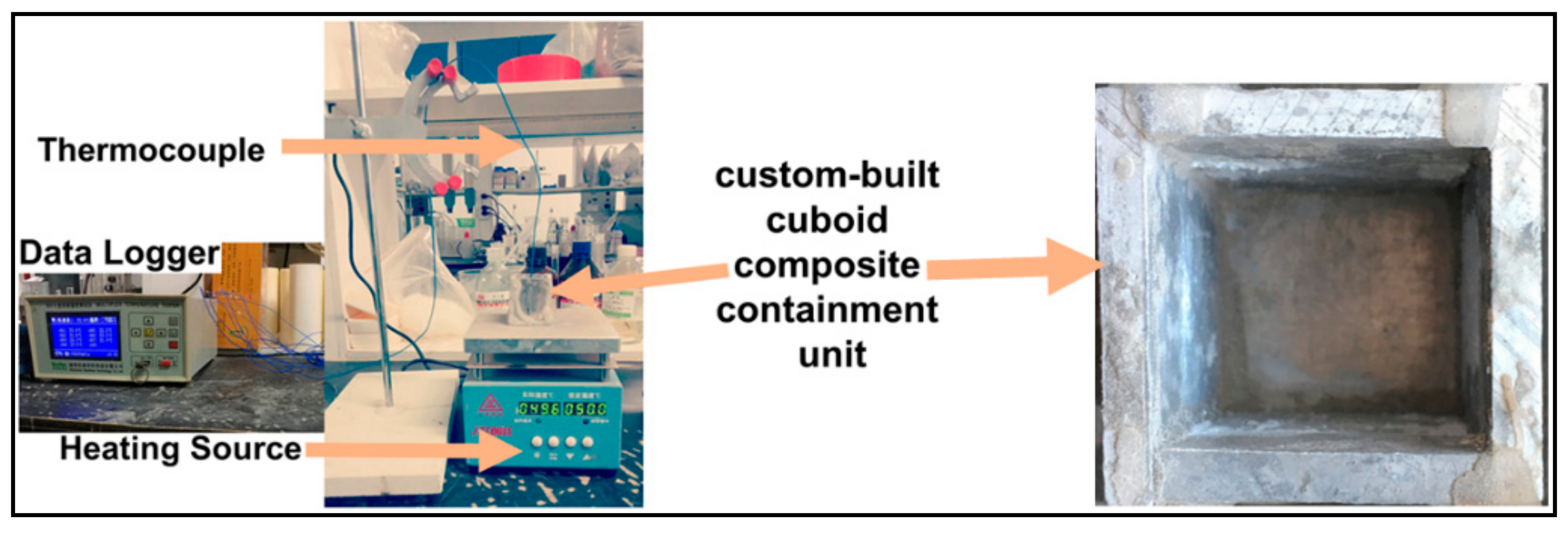
3.2.1. Experimental Evaluation

TSTBs were manufactured by employing TC5 and thermal performance is assessed through a series of transient thermal storage/release analyses. The thickness of the TSTBs was constructed with varied thicknesses of 10 mm and 15 mm, followed by their casting onto the ordinary clay-bricks through the cement-water paste, as shown in Figure 4a–d. Later, TSTB-pasted clay-bricks are employed to build a prototype wall, as depicted in Figure 4e.
The constant temperature of 50 °C was maintained at the prototype wall by a high-temperature lamp that is placed at an axial distance of 520 mm. Two thermocouples (T-1 and T-2) were inserted into the TSTBs by making a small hole of 1.5 mm. Furthermore, these thermocouples were attached with the data acquisition system (SH-X). A schematic layout diagram of the transient thermal analysis of the brick is shown in Figure 5. By implementing the heat source temperature of 50 °C, the objective is to investigate the worst scenarios of the hottest summer days, for example, of the Asian and Gulf regions. Thermal analysis of the clay-brick is presented in Figure 6 by black color curve, demonstrating the fast-uprising temperature that approaches the upper limit of the comfort zone (27 °C) in just 100 s. It implies no temperature control with the clay-bricks working under sensible heat transfer mode where the relatively high thermal conductivity of clay-brick ingredients (that is, ~0.5 Wm−1K−1) contribute to accelerating the temperature. Therefore, the need for temperature control is necessitated. In contrast, the TSTBs represent a completely different temperature trend. All TSTBs undergo a slightly non-linear temperature trend under sensible heat transfer mode in the beginning, followed by an isothermal zone consisting of latent heat mode. In TSTB10, the isothermal zone is quite apparent which is ascribed to the small thickness, inducing the quick thermal response based on which the phase change region is crossed sooner. Consequently, the temperature retardation time conforming to the human comfort zone is around 1200 s, providing better temperature control capacity compared with the clay-bricks. In TSTB15, the isothermal zone is large with a slower thermal response due to the large thickness, which is therefore highly fruitful in extending the temperature retardation time to around 1600 s. The overall reasons for the effective performance of the TSTBs are thus attributable to the optimal percent contents of the OD, its latent heat and the low thermal conductivity of the composites. Since the more percent contents of paraffin waxes are not allowed in the TSTBs, the only viable option to maintain the large temperature retardation durations is the large thickness of PCM-based bricks depending on the application suitability.
Next, the heat transfer mechanism and numerical analysis were included, helping understand the heat transfer and phase change energy storage mechanism.

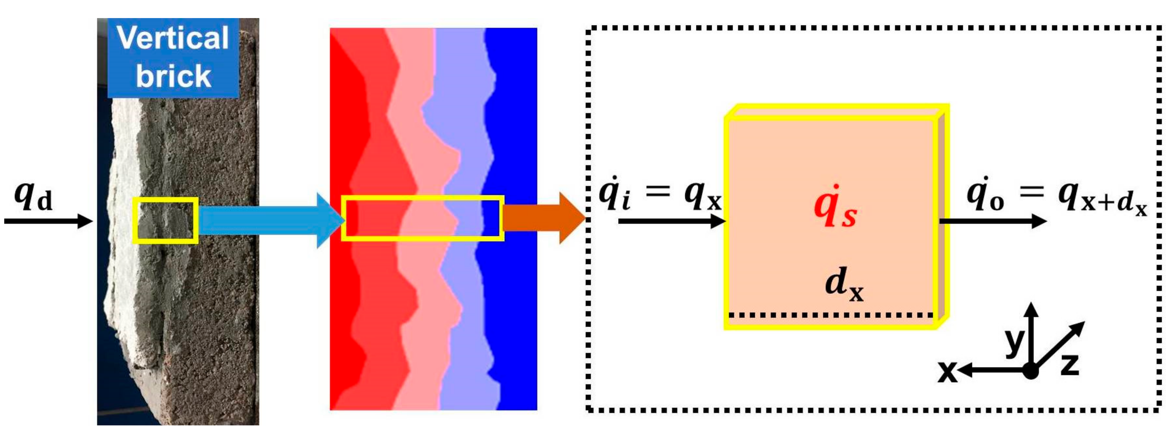
3.2.2. Numerical Modeling and Analysis

A high-temperature lamp (220 V–160 W) was used as a heat source, providing the heat dissipation as follows:
q d = I 2 R
Through an infinitesimal small control volume within the brick as schematized in Figure 7, the dissipated heat qd is considered to be the rate of heat input qi which is then resolved into the rate of heat storage qs and rate of heat out qo, as given below:
q ˙ i = m q ˙ s + q ˙ o  
where m is the mass of thermal storage material with density ρ contained within the control volume of area A and axial length dx.
With the heat flow notations as depicted in Figure 7, the above equation becomes:
q x = A d x d q s d t + q x + d x
where ρAdx is the mass contained within the control volume, and dqs/dt is the rate of change of thermal storage. With help of Taylor’s series expansion on qo and adopting the first two terms, it is obtained:
q x + d x = q x + d q x d x d x
By substituting the above equation and rearranging:
d q x d x d x = A d x d q s d t
qx transfers through a unit area A of control volume in a unit time t, inducing the unidirectional temperature gradient dT/dx within TSTBs, as follows:
q x A d T d x
q x = k TSTB A d T d x
where k is the thermal conductivity of TSTBs. Replacing the qx in equation with help of equation yields the mathematical model encompassing, second order temperature gradient and rate of thermal storage, as follows:
k TSTB d 2 T d x 2 = TSTB d q s d t
The mathematical model is termed a phase change-based thermal equation, simultaneously describing the thermal conduction and thermal storage. Comparing the developed mathematical model with [47], it is inferred that the adopted shell energy analysis is quite a suitable method to entirely describe the phase-change behaviors. For TSTBs, qs is contributed by the sensible heat and latent heat. The employed PCM undergo three kinds of transition states, leading to the pre-sensible heat storage cps, solid-liquid latent heat storage Lsl and post-sensible heat storage cpl. Therefore, total heat storage for TSTBs qs/TSTBs comprising mass m of PCM is given by the sum of all transition states. Accordingly, the equation becomes:
k TSTB d 2 T d x 2 = TSTB d d t   T i T s c p s   d T + L sl + T l T f c p l   d T
Furthermore, this phase-change-based heat equation is numerically solved using ANSYS Fluent tool which works through finite element analysis based on the enthalpy-porosity approach. In order to deal with solidification/melting phenomena, Fluent is equipped with temperature-dependent liquid fraction ( L f ) varying between 0 for solidification T < T s o l i d u s and 1 for melting ( T > T l i q u i d u s ) process. Mathematically, liquid fraction is defined as follows:
L i q u i d   f r a c t i o n   ( L f ) = T T s o l i d u s T l i q u i d u s T s o l i d u s           I f   T s o l i d u s T T l i q u i d u s
Thus, liquid fraction plays an important role in deciding the total thermal energy storage depending upon the extent of the composite’s temperature. Equations (9) and (10) are the fundamental governing equations providing iterative solutions for phase change-based systems.
Finite element analysis was executed through ANSYS Fluent by adopting the enthalpy–porosity method that can precisely address the phase-change systems. The following assumptions were considered [49,50]:
  • The melting temperature of OD was considered constant.
  • Radiative heat losses were ignored.
  • Convective heat transfer within TSTBs was ignored, and TSTBs are treated as solid.
  • Based on the form–stability criterion, density change during thr solid–liquid phase change was ignored.
Numerical analysis was carried out on 2D models that are built in the ANSYS design modeler. The thermal properties of the TSTBs necessary for numerical analysis are enlisted in Table 2.
The dimensions of the clay-brick are 160 mm × 85 mm × 45 mm with a total number of grids in the mesh as 79120. The dimensions of the TSTBs are 160 mm × 85 mm × 55 mm (TSTB10) and 160 mm × 85 mm × 60 mm (TSTB15) with a total number of grids in the mesh as 96,320 and 106,640, respectively. The volume meshes were generated in the ICEM system adopting the physical preference of CFD and solver preference of Fluent. The quality of mesh was verified by the report quality function of solution setup, where orthogonal quality lies between 0–1. The orthogonal quality of the constructed models is 0.85, which is closer to 1 and confirms the reliability of mesh. In this case, only the energy balance equation works as discussed above. The initial temperatures of clay-brick and TSTBs are both 22 °C. The heat is transferred from the high-temperature lamp onto the bricks is considered in convective mode, so the boundary condition on the surface of bricks is taken to be the convection condition with the convective heat transfer coefficient of 30 W/m2K, and the boundary temperature is set to be 50 °C. Other boundary conditions are supposed to be adiabatic. The time step in the analysis is 1 s.
The results of numerical analysis and their validation through experimental results are demonstrated in Figure 8. The slight discrepancies between numerical and experimental solutions, particularly for clay-brick, are ascribed to the factors contributed by the surroundings and heat losses. For the qualitative comparison of numerical and experimental results, a t-test at equal and unequal variances was performed. The obtained p-values come out to be 0.0043 for clay-bricks, 0.0063 for TSTB10 and 0.0031 for TSTB15. The obtained p-values strengthen the argument that experimental results have a good match with the numerical results since the p-value of less than 0.05 suggests no significant difference for the compared entities [37]. Overall, a good match was obtained for clay-bricks and TSTBs.

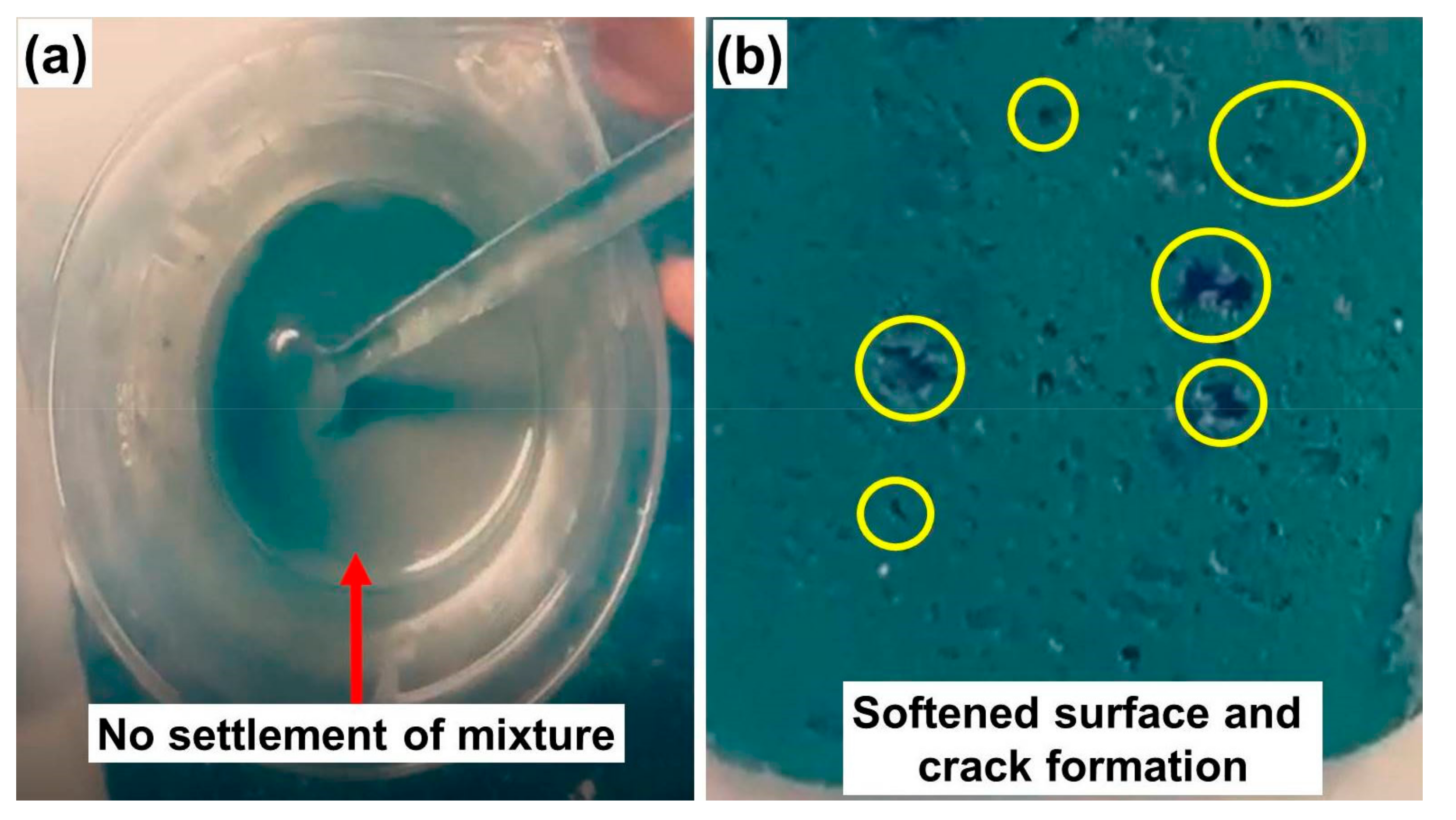
3.3. Hydro-Stability and Radioactivity Analysis of TSTBs

To demonstrate the stability of TSTBs in water, they were immersed in water for 7 days at room temperature of 18 ± 4 °C. After 7 days, TSTBs were subjected to heating for 1.5 h to observe any differences in shape and thermal behavior. It was visually observed that no cracks in the surface of TSTBs occurred, demonstrating the effective physical appearance, i.e., they retained their shape. Afterward, thermal analysis was performed that led to similar results as discussed above and depicted in Figure 6. This analysis further implies the promising resistive capability of TSTBs in rainy seasons. The current bricks are hydrophilic and it is included in our future intention to find ways to make them hydrophobic for the more befitting outdoor applications.
Since TSTBs are made of PG which is the basic scaffold, the only major concern to use the PG is its radioactivity which should be under safe limits. Environmental Protection Authority (EPA) and European Atomic Commission have set the safe limits of radioactivity as 370 Bq/kg and 500 Bq/kg, respectively. The radioactivity value of PG employed in TSTBs is 185 Bq/kg, which is much lower than the permissible limits. Therefore, TSTBs are declared to be safe and are feasible for indoor application too.

3.4. Thermal Comparison of TC5 with Other State-of-the-Art Systems

Vacuum insulation panels (VIPs), Gas-filled panels (GFPs) and Aerogels are among the most used class of the state of art systems that are being used for the thermal insulation of the buildings. Lower thermal conductivity, cost and simplicity in design are the most important key points in the selection of thermal insulating materials. VIPs have a thermal conductivity value of around 3~4 mWm−1K−1 [51] which may increase up to 8 mWm−1K−1 after a time span of 25 years due to the air and water diffusion through the core material of the VIPs [52]. Although VIPs have good thermal conductivity for the thermal insulation, they are associated with loss of performance over the span of time and mainly a high material cost [51]. GFPs have a thermal conductivity of 40 mWm−1K−1 which has certain limitations, as they do not contain any vacuums like VIPs and their structure is very sophisticated compared to the VIPs, therefore VIPs are considered better thermal insulators than the GFPs [52]. On the other hand, Aerogels have the lowest thermal conductivity of 4 mWm−1K−1 at 50 mbar pressure and a maximum of 13~14 mWm−1K−1 at ambient pressure which seems very attractive [52], but their cost is quite high as 52.9 €/m2 [51]. The above-mentioned problems are not associated with the TC5 (core material of TSTBs) as it is economical and consists of normal and easily available construction materials, such as cement, kaolin clay, PG and octadecane. Additionally, the other advantage of TC5 is that it does not offer any design and preparation complications unlike other above-mentioned thermal insulators and has a very low thermal conductivity of 0.35 Wm−1K1.

4. Conclusions

Form-stabilized TSTBs of varying thicknesses were fabricated from the thermal composite (TC5) and experimental as well as numerical thermal analyses were conducted on a prototype wall. Based on the experimental results and simulation, the following main conclusions can be listed:
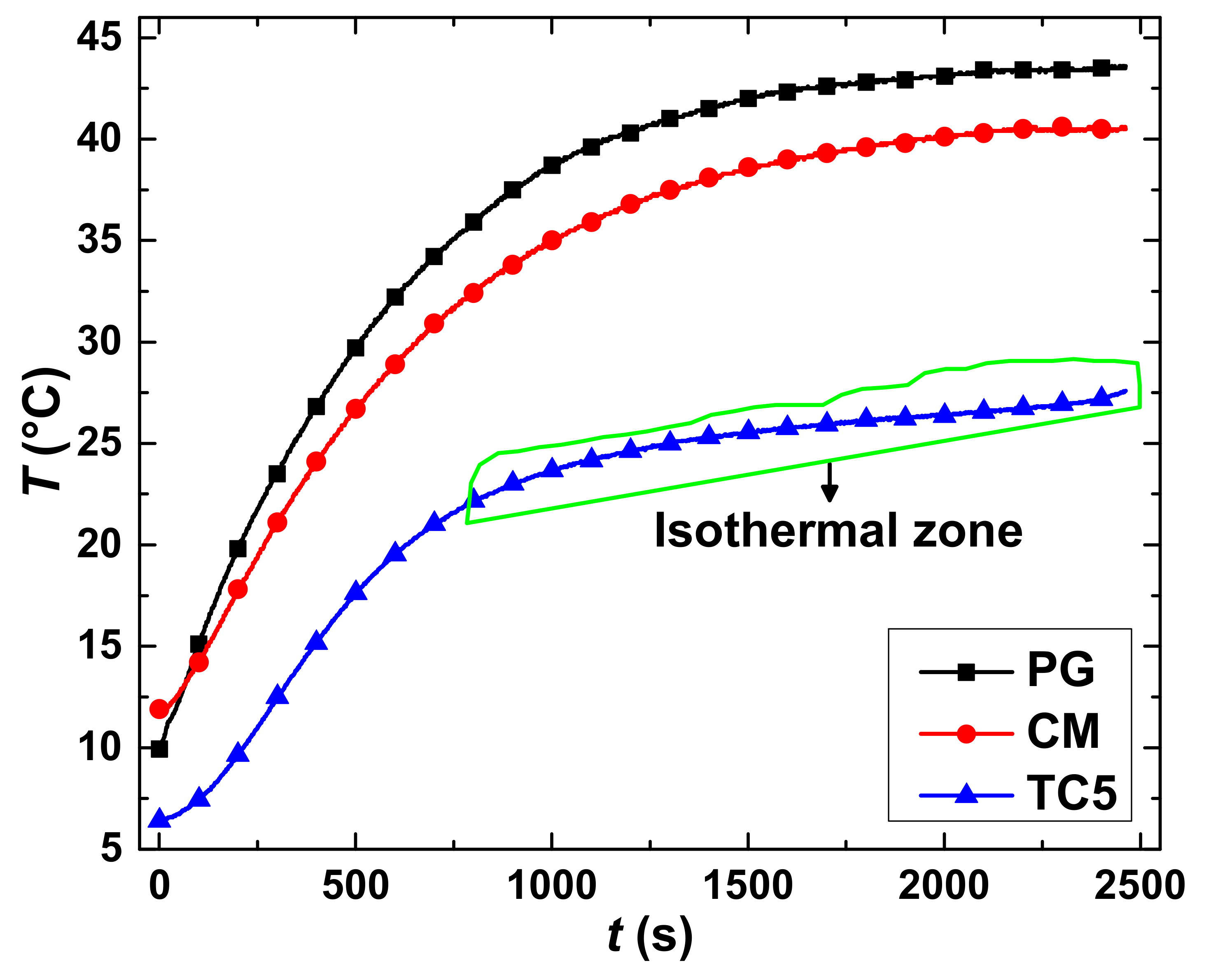
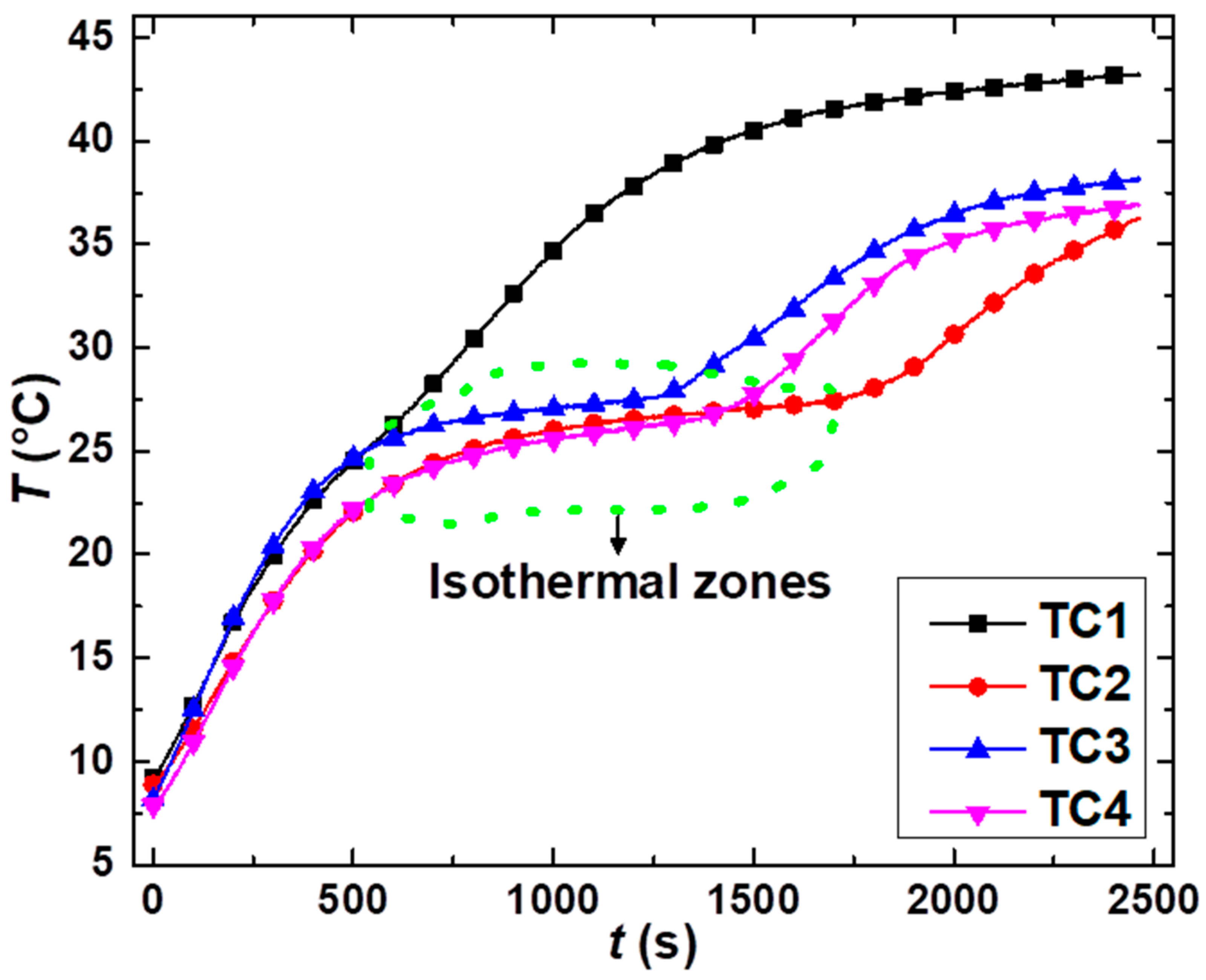
  • TC5 shows sufficient temperature retardation as a prominent isothermal zone appeared that lasted for around 1500 s in the case of TC5. The total time to reach the discomfort temperature zone for TC5 is also prolonged by more than 3000 s compared with 400 s of sole PG and CM.
  • Apart from OD, KC also plays a part in temperature retardation. It was shown above that the on-set and end-set of the isothermal zone take place during 25.6–28 °C for TC3 (5% of KC) by showing a temperature retardation time of 712 s; for TC4 (15% of KC), it occurs during 23.4–27.8 °C with the temperature retardation time of 915 s; as well as for TC5 (30% of KC), it begins from 22.1 °C and ends at 27.6 °C encompassing the temperature retardation time of 1662 s. These results show that KC has a temperature rendering tendency that is directly proportional to its mass percentage.
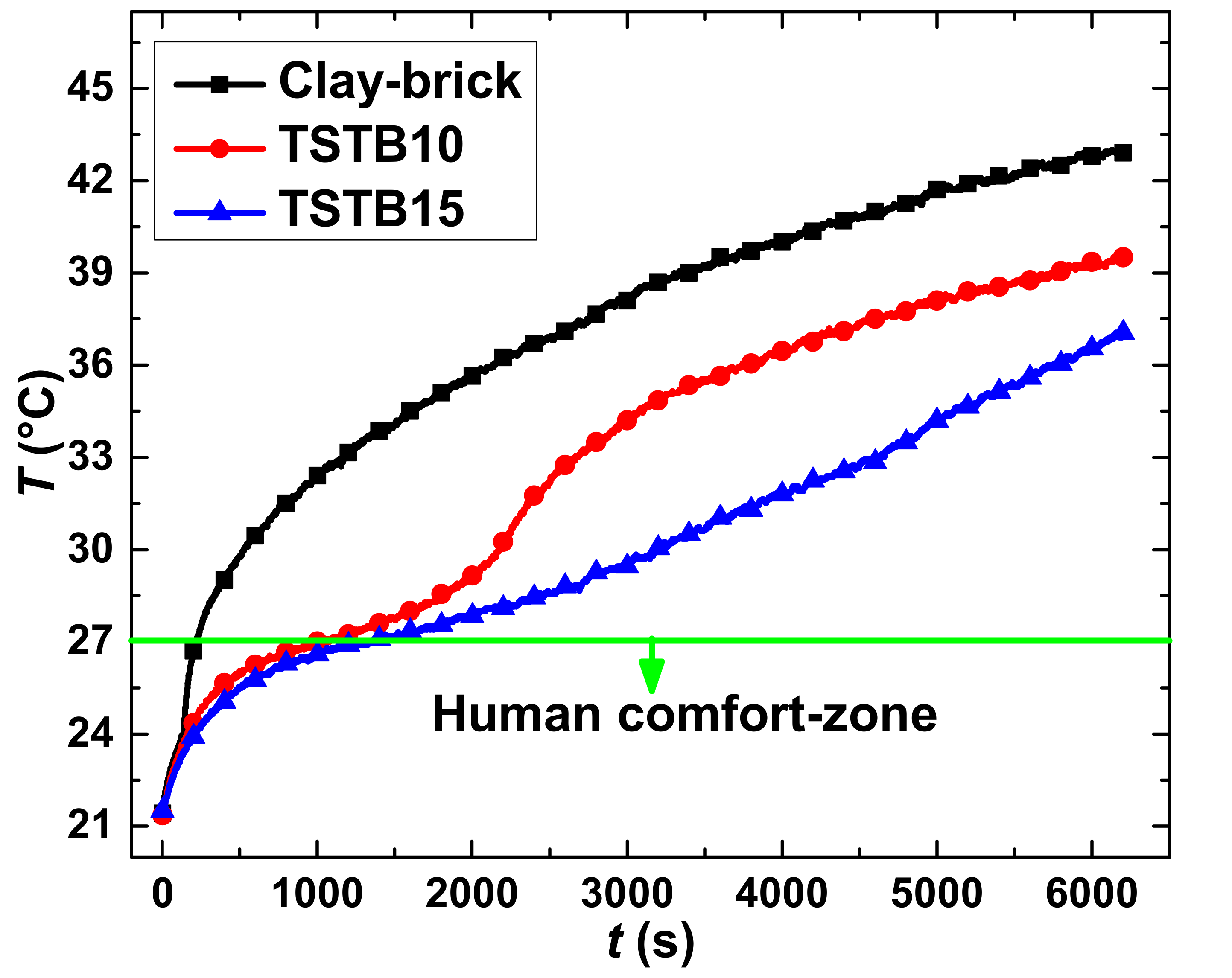
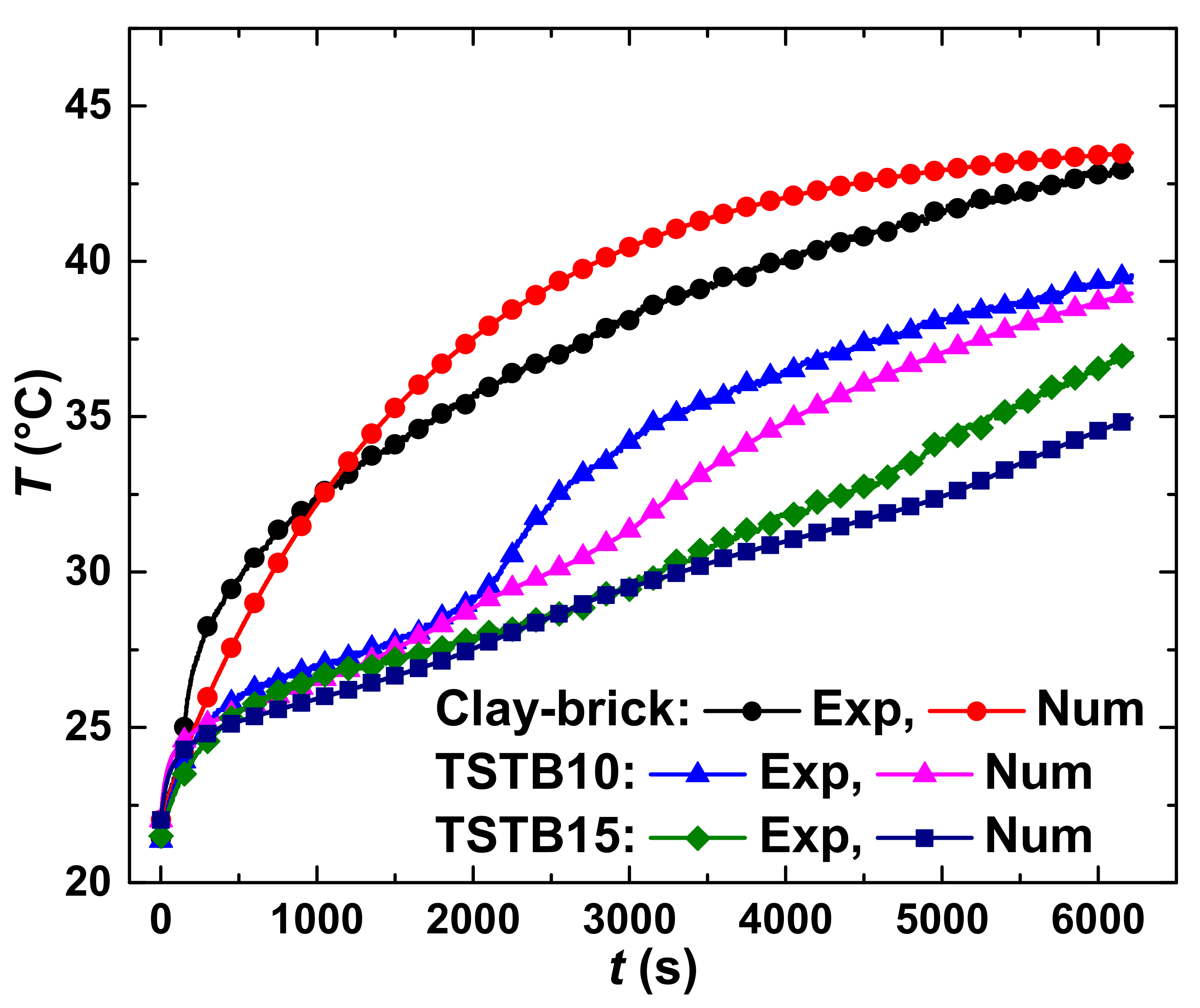
  • As the maximum percentage of the OD is 20% in the TSTBs and cannot be increased anymore, the only option to maintain the human comfort temperature is to increase the thickness of TSTBs in the prototype wall. The heat analysis showed that a thickness of 15 mm (TSTB15) has more temperature retardation than that of TSTB10.
  • The radioactivity test confirmed that the PG can be used in indoor and outdoor applications without the radioactivity risks. The radioactivity of the currently used PG is 185 Bq/kg, which is greatly less than the international standards.
Overall, a good match between the experimental and numerical results was established, depicting the cross-validation. Therefore, this work has promising practical applications in the thermal management of buildings. The current TSTBs are hydrophilic and the future intention is to convert these hydrophilic TSTBs into hydrophobic to bear the severe environmental effects.

Author Contributions

Conceptualization, S.I. and G.R.; methodology, S.I.; software, S.I. and G.R.; validation, S.I., G.R. and I.I.C.; formal analysis, S.I. and G.R. and Z.L.; investigation, J.T.; resources, J.T. and Y.L. and B.W.; data curation, S.I. and G.R.; writing—original draft preparation, S.I.; writing—review and editing, S.I. and G.R. and I.I.C. and M.A.K.; visualization, S.I. and M.A.K.; supervision, J.T.; project administration, J.T. and Y.L. and B.W.; funding acquisition, J.T. and Y.L. and B.W. All authors have read and agreed to the published version of the manuscript.

Funding

This research was funded by the National Science Foundation of China (No. 21576246), Geological Survey Project (DD20190590) and the Program for Innovative Research Team (in Science and Technology) in the University of Henan Province (19IRTSTHN028).

Institutional Review Board Statement

Not applicable.

Informed Consent Statement

Not applicable.

Acknowledgments

The financial support of the National Science Foundation of China (No. 21576246), Geological Survey Project (DD20190590) and the Program for Innovative Research Team (in Science and Technology) in the University of Henan Province (19IRTSTHN028) are gratefully acknowledged.

Conflicts of Interest

The authors declare no conflict of interest.

Appendix A

Appendix A.1. Morphology of Thermal Composites

The morphologies of the PG and TC5 were conducted via scanning electron microscopy SEM (ZEISS SE2), manufactured by ZEISS International, Oberkochen, Germany. The morphology of PG appeared to be non-porous consisting of slab-like flakes even after griding before the SEM analysis, as shown in Figure A1a, below which shows that the surface of the PG is enriched with rhombohedral flakes and shows some impurities which stick over the crystal surface of the PG. These impurities are mainly P2O5, F, organic matter, alkalis and MgO, etc. TC5 is a mixture (PG40%OD20%KC30%CM10%) and its morphology can be seen in Figure A1b below. No slab-like structures of PG were observed in TC5 because the melted OD sufficiently infused into the surface of PG which is governing the main part (40%) of the composite. The porous and fluffy KC intermingles with the rhombohedral flakes of PG and cement gets mixed well with the other ingredients of the TC5. Therefore, the morphology of TC5 depicts great matching compatibility of all the ingredients (PG/OD/KC/CM) that are tightly packed via inter-connected clustered units.
Figure A1. Morphology of (a) PG and (b) TC5.
Buildings 11 00357 g0a1

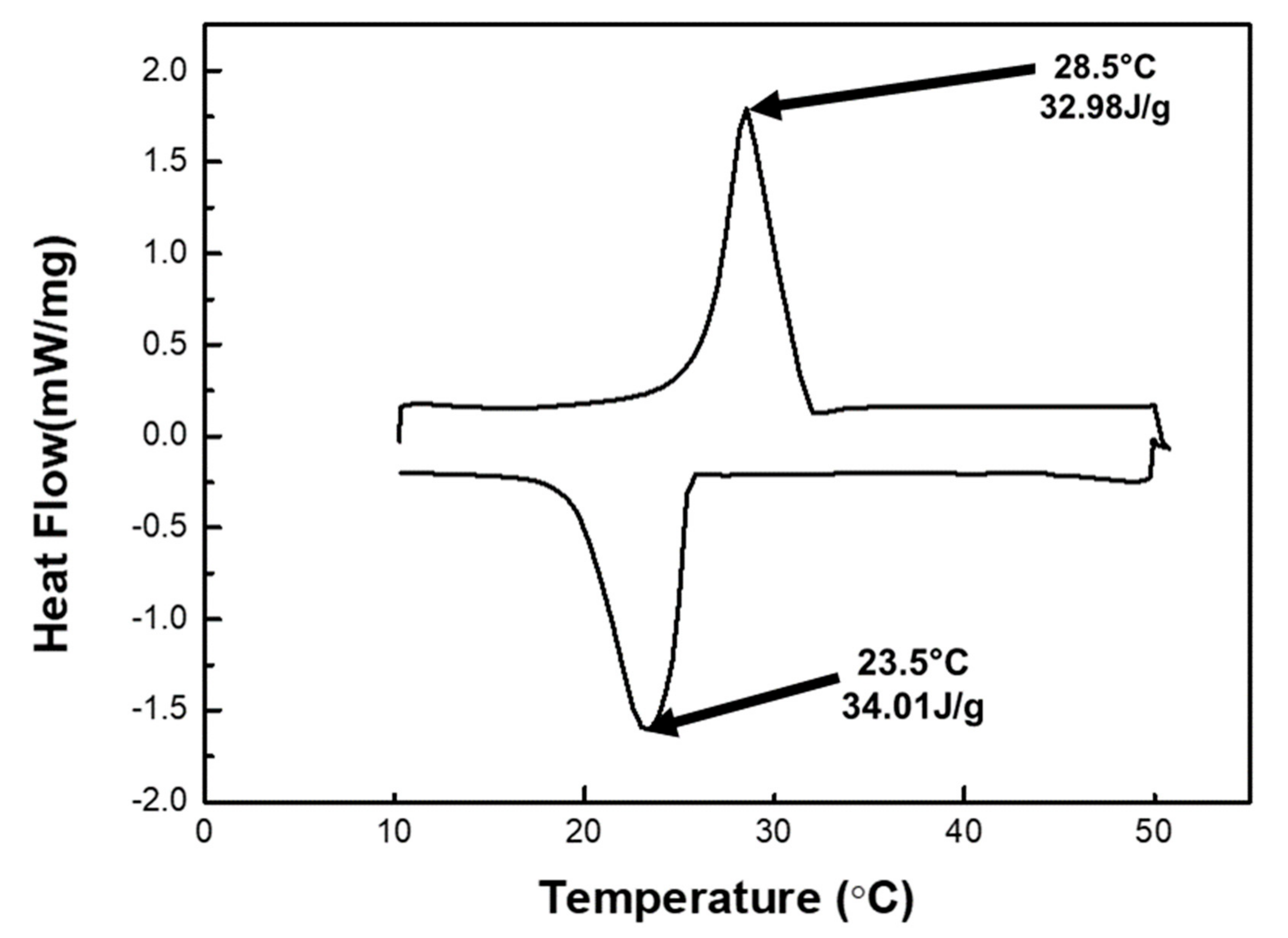
Appendix A.2. Temperature-Control Capacity and Latent Heat

Figure A2 below shows the thermal analysis of TC1–TC4. TC1 with composition PG95%OD5% and shows a minor transition region at the melting range of 24–28 °C but the duration of this isothermal region is too short (219 s) to consider TC1 as the optimal thermal composite because it does not meet both criteria, i.e., it neither provides the form-stability (based on the filter-based thermal annealing test) nor brings about the considerable temperature-control capacity so TC1 is not considered.
Figure A2. Transient thermal analysis of non-optimal thermal composites (TC1–TC4).
Buildings 11 00357 g0a2
TC2 shows a significant isothermal zone which starts from 23.7 °C and ends at 27.7 °C by showing temperature retardation of 1132 s. TC3 and TC4 have 5% and 15% KC and the role of KC is pivotal in keeping the flat isothermal zone. For example, the on-set and end-set of the isothermal zone take place at 25.6 °C and 28 °C for TC3 (5% of KC) entailing the temperature retardation time of 712 s; for TC4 (15% of KC), it starts from 23.4 °C and ends at 27.8 °C with the temperature retardation time of 915 s. Although TC2-TC4 can ensure a particular temperature-control capacity, they are not functional in providing robust form-stability due to the drainage of the OD. Thus, TC2-TC4 are also recommended to be neglected. Based on the optimal results of the shape stability and thermal storage capacity, TC5 (30%) is the optimal thermal composite which was used to build TSTBs and thermal transient analysis where the combined interplay of OD and KC favors to achieve the longer isothermal zone which begins from 22.1 °C and ends at 27.6 °C encompassing the temperature retardation time of 1662 s.
Figure A3 below shows the DSC analysis of the TC5. TC5 showed significant temperature retardation and energy storage capacity which is attributed to the latent heat storage capacity and lower thermal conductivity of TC5 (0.35 Wm−1K−1). Figure A3 below shows a narrow peak that exhibits the solid–liquid phase change of OD. The latent heat of TC5 is 34 J/g. The temperature of 23.5°C (melting point) is the on-set temperature and 28.5 °C (freezing point) is the end-set temperature of the isothermal zone of the TC5. The melting and freeing latent heat of TC5 are 34.01 J/g and 32.98 J/g, respectively. The latent heat of TC5 is relatively lower than that of the OD (207 J/g [34]), which is due to its percent contents (20%) in the thermal composite.
Figure A3. Latent heat of TC5.
Buildings 11 00357 g0a3

Appendix A.3. Challenges during the Composite Preparation Process

As mentioned earlier in Section 3.1 that 20% of OD in TC5 is the maximum threshold quantity that could be introduced, and increasing the percent contents higher than 20% inhibits the settlement of the ingredients even after vigorous stirring and residence time of 12 h. For example, when the percent contents of OD are increased to 40% (TC6 in Table 1), it becomes hard to stabilize the composite such that bricks cannot be made and the corresponding mixture state of TC6 can be seen in Figure A4a below. On the other hand, when percent contents of OD and PG are decreased to 30% with the addition of 30% KC (TC7 in Table 1), the composite is stabilized and can be converted into bricks, but at high temperature (constant 60 °C heater temperature), the bricks are softened and become unable to control the OD drainage as can be seen in Figure A4b below. It is also concluded here that 40% PG is the threshold value to give the desired strength to the optimal thermal composite (TC5).
Figure A4. Challenges during composite preparation for (a) TC6 and (b) TC7.
Buildings 11 00357 g0a4

References

  1. 2020 Global Status Report for Buildings and Construction. Available online: https://wedocs.unep.org/bitstream/handle/20.500.11822/34572/GSR_ES.pdf?sequence=3&isAllowed=y (accessed on 28 July 2021).
  2. Hekimoğlu, G.; Sari, A. Fly ash/octadecane shape-stabilized composite PCMs doped with carbon-based Nanoadditives for thermal regulation applications. Energy Fuels 2021, 35, 1786–1795. [Google Scholar] [CrossRef]
  3. Mukhtar, M.; Ameyaw, B.; Yimen, N.; Zhang, Q.; Bamisile, O.; Adun, H.; Dagbasi, M. Building retrofit and energy conservation/efficiency review: A techno-environ-economic assessment of heat pump system retrofit in housing stock. Sustainability 2021, 13, 983. [Google Scholar]
  4. Jeon, J.; Lee, J.H.; Seo, J.; Jeong, S.G.; Kim, S. Application of PCM thermal energy storage system to reduce building energy consumption. J. Therm. Anal. Calorim. 2012, 111, 279–288. [Google Scholar] [CrossRef]
  5. Díaz-González, F.; Sumperet, A.; Gomis-Bellmunt, O.; Villafáfila-Robles, R. A review of energy storage technologies for wind power applications. Renew. Sustain. Energy Rev. 2012, 16, 2154–2171. [Google Scholar] [CrossRef]
  6. Zhao, M.; Ming-Jia, L.; Max, Z.K.; Fan, Y. Novel designs of hybrid thermal energy storage system and operation strategies for concentrated solar power plant. Energy 2021, 216, 119281. [Google Scholar]
  7. Guan, X.; Qin, T.; Gao, S.; Yang, Y.; Zhang, G. Performance optimization of latent heat storage by structural parameters and operating conditions using Al-based alloy as phase change material. J. Renew. Sustain. Energy 2021, 13, 014101. [Google Scholar] [CrossRef]
  8. Jilte, R.; Afzal, A.; Panchal, S. A novel battery thermal management system using nano-enhanced phase change materials. Energy 2021, 219, 119564. [Google Scholar] [CrossRef]
  9. Zhang, S.; Feng, D.; Shi, L.; Wang, L.; Jin, Y.; Tian, L.; Li, Z.; Wang, G.; Zhao, L.; Yan, Y. A review of phase change heat transfer in shape-stabilized phase change materials (ss-PCMs) based on porous supports for thermal energy storage. Renew. Sustain. Energy Rev. 2020, 135, 110127. [Google Scholar] [CrossRef]
  10. Gulfam, R.; Saqib, I.; Samad, A. Paraffin Wax-Based Thermal Composites. In Paraffin-Thermal Energy Storage Applications; Zaki, E., Ed.; Intechopen: London, UK, 2021. [Google Scholar] [CrossRef]
  11. Sarier, N.; Onder, E. Organic phase change materials and their textile applications: An overview. Thermochim. Acta 2012, 540, 7–60. [Google Scholar] [CrossRef]
  12. Alehosseini, E.; Jafari, S.M. Micro/nano-encapsulated phase change materials (PCMs) as emerging materials for the food industry. Trends Food Sci. Technol. 2019, 91, 116–128. [Google Scholar] [CrossRef]
  13. Shen, Z.-G.; Chen, S.; Liu, X.; Chen, B. A review on thermal management performance enhancement of phase change materials for vehicle lithium-ion batteries. Renew. Sustain. Energy Rev. 2021, 148, 111301. [Google Scholar] [CrossRef]
  14. Huang, X.; Zhu, C.; Lin, Y.; Fang, G. Thermal properties and applications of microencapsulated PCM for thermal energy storage: A review. Appl. Therm. Eng. 2019, 147, 841–855. [Google Scholar] [CrossRef]
  15. Pandey, B.; Banerjee, R.; Sharma, A. Coupled EnergyPlus and CFD analysis of PCM for thermal management of buildings. Energy Build. 2020, 231, 110598. [Google Scholar] [CrossRef]
  16. Pielichowska, K.; Pielichowski, K. Phase change materials for thermal energy storage. Prog. Mater. Sci. 2014, 65, 67–123. [Google Scholar] [CrossRef]
  17. Rathore, P.K.S.; Shukla, S.K. Enhanced thermophysical properties of organic PCM through shape stabilization for thermal energy storage in buildings: A state of the art review. Energy Build. 2021, 236, 110799. [Google Scholar] [CrossRef]
  18. Hekimoğlu, G.; Nas, M.; Ouikhalfan, M.; Sari, A.; Tyagi, V.V.; Sharma, R.K.; Kurbetci, S.; Saleh, T.A. Silica fume/capric acid-stearic acid PCM included-cementitious composite for thermal controlling of buildings: Thermal energy storage and mechanical properties. Energy 2021, 219, 119588. [Google Scholar] [CrossRef]
  19. Veerakumar, C.; Sreekumar, A. Thermo-physical investigation and experimental discharge characteristics of lauryl alcohol as a potential phase change material for thermal management in buildings. Renew. Energy 2019, 148, 492–503. [Google Scholar] [CrossRef]
  20. Sharifi, N.P.; Shaikh, A.A.N.; Sakulich, A.R. Application of phase change materials in gypsum boards to meet building energy conservation goals. Energy Build. 2017, 138, 455–467. [Google Scholar] [CrossRef]
  21. Du, K.; Calautit, J.; Wang, Z.; Wu, Y.; Liu, H. A review of the applications of phase change materials in cooling heating and power generation in different temperature ranges. Appl. Energy 2018, 220, 242–273. [Google Scholar] [CrossRef]
  22. Kenisarin, M.M. High-temperature phase change materials for thermal energy storage. Renew. Sustain. Energy Rev. 2010, 14, 955–970. [Google Scholar] [CrossRef]
  23. Raza, G.; Zhang, P.; Meng, Z. Advanced thermal systems driven by paraffin-based phase change materials—A review. Appl. Energy 2019, 238, 582–611. [Google Scholar] [CrossRef]
  24. Kant, K.; Shukla, A.; Sharma, A.; Kumar, A.; Jain, A. Thermal energy storage based solar drying systems: A review. Innov. Food Sci. Emerg. Technol. 2016, 34, 86–99. [Google Scholar] [CrossRef]
  25. Ibáñez, M.; Lázaro, A.; Zalba, B.; Cabeza, L.F. An approach to the simulation of PCMs in building applications using TRNSYS. Appl. Therm. Eng. 2005, 25, 1796–1807. [Google Scholar] [CrossRef]
  26. Wu, S.; Yan, T.; Kuai, Z.; Pan, W. Thermal conductivity enhancement on phase change materials for thermalenergy storage: A review. Energy Storage Mater. 2020, 25, 251–295. [Google Scholar] [CrossRef]
  27. Baetens, R.; Jelle, B.P.; Gustavsen, A. Phase change materials for building applications: A state-of-the-art review. Energy Build. 2010, 42, 1361–1368. [Google Scholar] [CrossRef] [Green Version]
  28. Memon, S.A. Phase change materials integrated in building walls: A state of the art review. Renew. Sustain. Energy Rev. 2014, 31, 870–906. [Google Scholar] [CrossRef]
  29. Tang, F.; Liu, L.; Alva, G.; Jia, Y.; Fang, G. Synthesis and properties of microencapsulated octadecane with silica shell as shape—Stabilized thermal energy storage materials. Sol. Energy Mater. Sol. Cells 2017, 160, 1–6. [Google Scholar] [CrossRef]
  30. Khudhair, A.M.; Farid, M.M. A review on energy conservation in building applications with thermal storage by latent heat using phase change materials. Energy Convers. Manag. 2004, 45, 263–275. [Google Scholar] [CrossRef]
  31. Umair, M.M.; Zhang, Y.; Iqbal, K.; Zhang, S.; Tang, B. Novel strategies and supporting materials applied to shape-stabilize organic phase change materials for thermal energy storage—A review. Appl. Energy 2019, 235, 846–873. [Google Scholar] [CrossRef]
  32. Heim, D. Isothermal storage of solar energy in building construction. Renew. Energy 2010, 35, 788–796. [Google Scholar] [CrossRef]
  33. Sadineni, S.B.; Madala, S.; Boehm, R.F. Passive building energy savings: A review of building envelope components. Renew. Sustain. Energy Rev. 2011, 15, 3617–3631. [Google Scholar] [CrossRef]
  34. Shen, H.; Tan, H.; Tzempelikos, A. The effect of reflective coatings on building surface temperatures, indoor environment and energy consumption—An experimental study. Energy Build. 2010, 43, 573–580. [Google Scholar] [CrossRef]
  35. Zhou, D.; Zhao, C.Y.; Tian, Y. Review on thermal energy storage with phase change materials (PCMs) in building applications. Appl. Energy 2012, 92, 593–605. [Google Scholar] [CrossRef] [Green Version]
  36. Kenisarin, M.; Mahkamov, K. Solar energy storage using phase change materials. Renew. Sustain. Energy Rev. 2007, 11, 1913–1965. [Google Scholar] [CrossRef]
  37. Oró, E.; de Gracia, A.; Castell, A.; Farid, M.M.; Cabeza, L.F. Review on phase change materials (PCMs) for cold thermal energy storage applications. Appl. Energy 2012, 99, 513–533. [Google Scholar] [CrossRef] [Green Version]
  38. Shilei, L.; Neng, Z.; Guohui, F. Eutectic mixtures of capric acid and lauric acid applied in building wallboards for heat energy storage. Energy Build. 2006, 38, 708–711. [Google Scholar] [CrossRef]
  39. Beltrán, R.D.; Martínez-Gomez, J. Analysis of phase change materials (PCM) for building wallboards based on the effect of environment. J. Build. Eng. 2019, 24, 100726. [Google Scholar] [CrossRef]
  40. Li, L.; Yu, H.; Liu, R. Research on composite-phase change materials (PCMs)-bricks in the west wall of room-scale cubicle: Mid-season and summer day cases. Build. Environ. 2017, 123, 494–503. [Google Scholar] [CrossRef]
  41. Nghana, B.; Tariku, F. Phase change material’s (PCM) impacts on the energy performance and thermal comfort of buildings in a mild climate. Build. Environ. 2016, 99, 221–238. [Google Scholar] [CrossRef]
  42. Cabeza, L.F.; Castellón, C.; Nogués, M.; Medrano, M.; Leppers, R.; Zubillaga, O. Use of microencapsulated PCM in concrete walls for energy savings. Energy Build. 2007, 39, 113–119. [Google Scholar] [CrossRef]
  43. Ling, H.; Chen, C.; Wei, S.; Guan, Y.; Ma, C.; Xie, G.; Li, N.; Chen, Z. Effect of phase change materials on indoor thermal environment under different weather conditions and over a long time. Appl. Energy 2015, 140, 329–337. [Google Scholar] [CrossRef]
  44. Zhang, Z.; Shi, G.; Wang, S.; Fang, X.; Liu, X. Thermal energy storage cement mortar containing n-octadecane/expanded graphite composite phase change material. Renew. Energy 2012, 50, 670–675. [Google Scholar] [CrossRef]
  45. Islam, N.; Ahmed, D.H. Delaying the temperature fluctuations through PCM integrated building walls—Room conditions, PCM placement, and temperature of the heat sources. Energy Storage 2021, e245. [Google Scholar] [CrossRef]
  46. Hekimoğlu, G.; Nas, M.; Ouikhalfan, M.; Sari, A.; Kurbetci, S.; Tyagi, V.V.; Sharma, R.K.; Saleh, T.A. Thermal management performance and mechanical properties of a novel cementitious composite containing fly ash/lauric acid-myristic acid as form-stable phase change material. Constr. Build. Mater. 2021, 274, 122105. [Google Scholar] [CrossRef]
  47. Cai, Q.; Jiang, J.; Ma, B.; Shao, Z.; Hu, Y.; Qian, B.; Wang, L. Efficient removal of phosphate impurities in waste phosphogypsum for the production of cement. Sci. Total. Environ. 2021, 780, 146600. [Google Scholar] [CrossRef] [PubMed]
  48. Islam, G.M.S.; Chowdhury, F.H.; Raihan, M.T.; Amit, S.K.S.; Islam, M.R. Effect of phosphogypsum on the properties of portland cement. Proced. Eng. 2017, 171, 744–751. [Google Scholar] [CrossRef]
  49. Ling, Z.; Wang, F.; Fang, X.; Gao, X.; Zhang, Z. A hybrid thermal management system for lithium ion batteries combining phase change materials with forced-air cooling. Appl. Energy. 2015, 148, 403–409. [Google Scholar] [CrossRef] [Green Version]
  50. Gulfam, R.; Zhu, W.; Xu, L.; Cheema, I.I.; Sheng, P.; Zhao, G.; Deng, Y. Design, fabrication and numerical analysis of compact thermal management system integrated with composite phase change material and thermal bridge. Energy Convers. Manag. 2018, 156, 25–33. [Google Scholar] [CrossRef]
  51. Gonçalvesa, M.; Simõesa, N.; Serraa, C.; Flores-Colen, I. A review of the challenges posed by the use of vacuum panels in external insulation finishing systems. Appl. Energy 2020, 257, 114028. [Google Scholar] [CrossRef]
  52. Jelle, B.P. Traditional, state-of-the-art and future thermal building insulation materials and solutions—Properties, requirements and possibilities. Energy Build. 2011, 43, 2549–2563. [Google Scholar] [CrossRef] [Green Version]
Figure 1. Experimental method description for the thermal analysis of TCs.
Buildings 11 00357 g001
Figure 2. Filter-based OD drainage test of (a) TC3, (b) TC4 and (c) TC5. The red-encircled area depicts the drainage.
Buildings 11 00357 g002
Figure 3. Thermal analysis of sole phosphogypsum (PG), cement (CM) and TC5.
Buildings 11 00357 g003
Figure 4. (a) TSTB10, (b) TSTB10-pasted clay-brick, (c) TSTB15, (d) TSTB15-pasted clay-brick, and (e) Prototype wall and experimental setup for thermal analysis.
Buildings 11 00357 g004
Figure 5. Schematic diagram for the thermal analysis of TSTBs.
Buildings 11 00357 g005
Figure 6. Thermal analysis of clay-brick and TSTBs.
Buildings 11 00357 g006
Figure 7. Heat transfer and distribution mechanism through bricks.
Buildings 11 00357 g007
Figure 8. Numerical (Num) results and their validation via experimental (Exp) results.
Buildings 11 00357 g008
Table 1. Thermal composites (TCs) with various percent contents.
PCM CompositesPG (wt.%)OD (wt.%)KC (wt.%)CM (wt.%)
TC195500
TC2802000
TC36520510
TC455201510
TC540203010
TC65040010
TC730303010
Table 2. Thermal properties of ingredients of TSTBs employed in numerical analysis.
Thermal PropertyValue
Density of clay/kg m−3 800
Specific capacity of clay/J kg−1 K−1 730
Thermal conductivity of clay/Wm−1K−10.55
Density of PCM/kg m−3 1894
Heat capacity of PCM/J kg−1 K−1 2000
Thermal conductivity of PCM/Wm−1K−10.29
Melting temperature/°C25
Latent heat/J kg−134,000
Publisher’s Note: MDPI stays neutral with regard to jurisdictional claims in published maps and institutional affiliations.

