Article

Deposits in Gas-fired Rotary Kiln for Limonite Magnetization-Reduction Roasting: Characteristics and Formation Mechanism

1
School of Metallurgy and Environment, Central South University, Changsha 410083, China
2
Changsha Research Institute of Mining and Metallurgy Co. Ltd., Changsha 410012, China
3
School of Minerals Processing and Bioengineering, Central South University, Changsha 410083, China
*
Authors to whom correspondence should be addressed.
Metals 2019, 9(7), 764; https://doi.org/10.3390/met9070764
Submission received: 4 June 2019 / Revised: 28 June 2019 / Accepted: 5 July 2019 / Published: 8 July 2019
(This article belongs to the Special Issue Advances in Pyrometallurgy)

Abstract

:
The formation mechanism of deposits in commercial gas-fired magnetization-reduction roasting rotary kiln was studied. The deposits ring adhered on the kiln wall based on the bonding of low melting point eutectic liquid phase, and the deposit adhered on the air duct head by impact deposition. The chemical composition and microstructure of the deposits sampled at different locations varied slightly. Besides a small amount of quartz and limonite, main phases in the deposits are fayalite, glass phase and magnetite. The formation of the deposits can be attributed to the derivation of low melting point eutectic of fine limonite and coal ash, and the solid state reaction between them. Coal ash, originated from the reduction coal, combining together with fine limonite particles, results in the accumulation of deposits on the kiln wall and air duct. Fayalite, the binder phase, was a key factor for deposit formation. The residual carbon in limonite may cause an over-reduction of limonite and produce FeO. Amid the roasting process, SiO2, originated from limonite and coal ash, may combine with FeO and reduce the liquefaction temperature, therewith liquid phase generates at high temperature zone, which can significantly promote the growth of deposits.

Graphical Abstract

1. Introduction

Due to the depletion of easy-processing iron ores, much attention has been paid to the utilization of refractory ores in recent years [1,2,3,4,5]. Limonite ore is a common refractory iron oxide ore with low grade, weak magnetic property and high gangue content. Although limonite ore is poorly responsive to conventional beneficiation techniques, magnetizing roasting-magnetic separation approach has been proved a promising solution for such refractory iron oxide ore beneficiation [1,6,7,8,9]. The limonite ore becomes porous, easy-to-be-reduced and the iron grade can be naturally enriched by the removal of crystal water which was banded with iron oxide after roasting process, then qualified iron concentrate can be obtained by the sequential magnetic separation [10].
Industrial-scale magnetization reduction roasting (MRR) was first implemented in Ukraine in the 1970s [11]. The MRR technology mainly include shaft furnace MRR, rotary kiln MRR, fluidized MRR, etc. [12]. Generally, shaft furnace MRR technology has problems such as low iron recovery rate, inefficient use of fine ores and high energy consumption [13]. Fluidized MRR technology has been reported by many researchers [14,15,16,17], but due to the equipment design and control problems in its industrialization, it stays still at laboratory or pilot level. Rotary kiln magnetization reduction roasting technique has been applied in limonite processing lines. To explore the limonite ore resource in Xinjiang, China, a Φ 4 m × 60 m rotary kiln MRR system was designed [18]. Till late of 2010, five MRR systems with the single capacity of 55 t/h were constructed and stable operation was achieved. With this roasting-magnetic separation process, the average concentrate grade reached 61–62%, and the iron recovery amounted to about 90%, which realized the economic and effective utilization of limonite ore in actual practice.
However, amid the MRR production, it was usually found that there were deposits adhered on the kiln wall at the discharge end and the top of the air duct in the kiln [18]. The deposit formation is a serious problem which can significantly reduce the roasting product quality and the operation efficiency. In grate-kiln for hematite pellet production, the characteristics and mechanism of the deposits, especially, the influence of coal ash, were widely studied. The results show that the main formation mechanism of deposits in rotary kiln is the crystallization and diffusion hematite. The liquid phase plays a secondary role in the deposit formation [19,20], while the silicate phase also plays an important role in deposit solidification [21]. Coal ash can enhance the bonding strength of the iron ore powder compact [22]. A combination of coal ash, silicide glass phase, alum inosilicate molten phase and low melting point liquid phase promotes the formation and accumulation of deposits, which eventually results in deteriorate normal production conditions. In addition, studies show the formation of deposit mainly depends on the accumulation of powder stocked on kiln wall, and the powder concretion speed turns faster at higher temperature [23]. Research has shown that [24] compared to other fuels, the usage of clean fuel is greatly beneficial in reducing of deposit formation rate.
As the commercial application of limonite MRR production is rare, there were few reports on its deposit phenomena. Run-of-mine limonite ore was processed by the aforementioned Φ 4 m × 60 m rotary kiln MRR plant in Xinjiang. Natural gas is used as the main fuel, while the reduction coal, mixed with limonite ore as raw material, and a certain amount of pulverized coal was injected into the rotary kiln by a coal gun to adjust the atmosphere and temperature. The total amount of coal was about 4–8% (mass weight) of limonite ore. Serious deposit problem occurred during its beginning operation. Therefore, it is essential to investigate the deposit formation mechanism. As the MRR and oxidizing pellet processes are different in terms of raw materials, reaction atmosphere and temperature, the formation mechanism and characteristics of the deposits may also be different. The formation mechanism of deposit in a gas-fired rotary kiln for limonite MRR is still not very clear, so it is essential to reveal the mechanism and take some practical measures to mitigate these occurrences to improve product quality and productivity.

2. Materials and Methods

2.1. Materials

2.1.1. Chemical Analysis on Raw Materials

The chemical compositions and ignition loss of limonite ore are listed in Table 1. The coal properties and ash components are listed in Table 2 and Table 3.

2.1.2. Locations in the Kiln Where Deposits Were Collected

Three kinds of deposit samples from different locations, one on the air duct and the other two on the wall, were studied. The collection position on the cross section of the deposit ring on kiln wall is shown in Figure 1. The samples collected from the upper layer, i.e., above the midline of the longitudinal section of the deposit ring were labeled as S1, while those collected beneath the middle line adjacent to the kiln wall were labeled as S2. Four samples were collected randomly of each layer along the kiln wall deposit ring circumference. The size of a single sample was about 20 cm × 20 cm × 15 cm (length × width × thickness). The deposit on the top of the first of the four air duct near the discharge end was marked as S3, and there were no deposits on other air ducts behind.

2.2. Characterization Methods

The chemical compositions of limonite ore and deposit samples were determined using Chinese Iron Ore Chemical Analysis Methods Standard [25]. The chemical composition of coal ash and the analysis of steam coal were conducted according to GB/T 1574-2007and GB/T 212-2008, respectively. The soft-melting characteristics of coal ash, limonite ore and deposit samples were analyzed according to GB/T 212-2008. The phase composition of deposit samples was determined by X-ray diffraction technique (XRD, Rigaku D/max-rA, Rigaku Co., Akishima, Japan). A scanning electron microscopy (SEM, JSM-6490LV, JEOL Co., Ltd, Akishima, Japan) coupled with energy dispersive spectra analyzer (EDS, NEPTUNE TEXS HP, EDAX Inc. Co., Ltd., McKee Drive Mahwah, NJ, USA) was used to investigate the elemental distributions of the deposit samples. The mineralogy identification analysis of the deposit samples was observed using an automatic polarizing microscope (DM4500P, Leica Microsystems, Wetzlar, Germany). FactSage® 7.2 software was used to calculate the liquid phase range and liquefaction temperature change of the iron silicate phase in the deposit samples at different FeO contents in Al2O3-SiO2-CaO-FeO system with the corresponding databases “FToxid” and “FactPS”.

3. Results and Discussion

3.1. In-Line Observation of Deposits

The deposit ring of limonite MRR production generates at the discharge end. Its height increased gradually along with the extension distance to the charge end. Located at a distance of 8 to 10 m in the kiln from the discharge end, the deposit ring can accumulate to over one-meter high. Its height drops rapidly after passing through the high temperature zone. Figure 2 shows the actual situation and longitudinal section of the deposit ring in the rotary kiln. The accumulative deposit ring height may affect the flow of raw materials and flue gas. The temperature in the region before the ring increased, while that behind the ring declined remarkably, resulting in deterioration of process conditions. When the height of the deposit ring attained 0.8–1.0 m or more, as illustrated in Figure 2b, the flow of flue gas and raw materials will be hindered by the narrowed channel of the deposition ring. With the accumulation of a large amount of raw materials between the deposit ring and the charge end of the kiln, the motor risks overloading. If the deposit ring cannot fall off automatically, it will artificially interfere to pause the operation and peel off the deposit ring after cooling down. As the deposit ring needs 3 to 5 days to be removed per time, this reduces MRR production efficiency.
Compared with the oxidized pellets production, which needs to be roasted generally at temperatures over 1200 °C [20], the working temperature for the limonite MRR production is only 700–800 °C. Nevertheless, serious deposition occurs and the deposits grow very fast. The height of the deposit ring on kiln wall can reach 0.4–0.8 m in 5–10 days and has seriously negative impact on limonite MRR production.

3.2. Appearance of Deposits

Figure 3 shows the appearance of the deposit samples. It can be seen that all these samples are of grayish-black, while some of the deposits are stained with red Fe2O3 powder because the atmosphere in the kiln was turned into oxidizing when quitting production. Showing fused state and metallic luster, sample S1 possesses well-developed pores, and there is a lot granular limonite adhered to its surface (Figure 3a). Sample S2 is mainly composed of fine-grained materials with obvious stratification, which contains a small amount of granular limonite, and the pores in sample S2 are smaller than that of sample S1 (Figure 3c). Sample S3 has fine and uniform grain, loose in texture and there is no adherence of granular limonite (Figure 3d).

3.3. Chemical Composition of Deposits

The chemical compositions of deposit samples S1, S2 and S3 are listed in Table 4. Two results are listed based on the highest and lowest FeO levels of samples S1 and S2, respectively. Compared with the chemical compositions of iron ore (Table 1), it can be seen that the total Fe (TFe) grade of all the deposits increased to about 40% from 35.85% of raw materials, and the main composition of the iron oxides changes from Fe2O3 to FeO (wüstite). Analysis shows that the ignition loss of the limonite ore was 15.8% (Table 1); apparently, the TFe grade of the deposits increased as a result of the ignition loss of the limonite. Combined with the chemical compositions of iron ore and coal ash (Table 1 and Table 3), the increasing of SiO2, Al2O3, CaO, Na2O and K2O contents can be attributed to the addition of coal ash. Previous researches [19,20,21,22] indicated that the iron oxides phase of the hematite pellet production deposits was mainly Fe2O3 and trace FeO originated from the reduction of hematite by residual carbon particles. The difference is that the iron oxide phase of limonite MRR production deposit was mainly FeO and contains less Fe2O3. The reason for the difference might be that the production of hematite pellets are carried out in oxidizing atmosphere; on the contrary, the production of limonite MRR needs to maintain a reduced atmosphere in the rotary kiln by mixed 4–8% coal in limonite. Therefore, the over-reduction reaction occurs to form FeO when limonite passes through high temperature zone in the limonite MRR production. As can be calculated from Table 1, the alkalinity of the iron ore is only about 0.2; thus, the silicate phase can easily form, which may benefit the increase of FeO (wüstite) content. The presence of FeO played a very important role in the formation of the deposits, as it can chemically react with silica and other oxides to form high viscosity eutectic liquid phase [26], reduce the melting point of a system significantly [27] and promotes the generation of liquid phase during the deposit formation.
The external deposit (S1) possesses more FeO and less Fe2O3 than the internal deposit (S2) (Table 4), while other components for both samples are almost the same. This phenomenon might be a result of varied reduction circumstances. For the internal deposit, as it is isolated from the reducing atmosphere, the reduction reaction of iron oxides can only be induced by residual carbon trapped in the deposit. For the external deposit, as it is closer to the flame, the higher temperature causes further over-reduction of iron oxides.
Compared with the deposit on kiln wall (S1, S2), sample S3 contains more SiO2, Al2O3 and CaO and less TFe and FeO. Generally, there are a lot of solid particles contained in the flue gas, mainly composed of coal ash and fine ore particles. There is more coal ash in S3 than in S1 and S2, as the coal ash has lower density than the disturbed limonite ore powder, and the content of coal ash in the flue gas is higher. However, based on the TFe content in Table 3 and Table 4, the disturbed limonite ore powder in flue gas also was an important component of sample S3. These particles in the flue gas inertial impact and compress bond to the surface on the top of air duct, chemical reaction occurs in the reducing atmosphere and local high temperature [28,29], and a distinct layered deposition structure was formed with the rotation of the kiln. It can be inferred that the superposition of inertial deposition and chemical reaction was the main reason for the deposition of coal ash and limonite ore powder on the air duct. In addition, as the zone where the air duct located is far away from the flame and has lower temperature, there occurs no visible melting in sample S3. Compared with sample S1 and S2, sample S3 has a more loose structure. It can easily be crushed by manpower, and, when it is large enough, it falls off naturally, which means that it has no remarkable effect on MRR production.

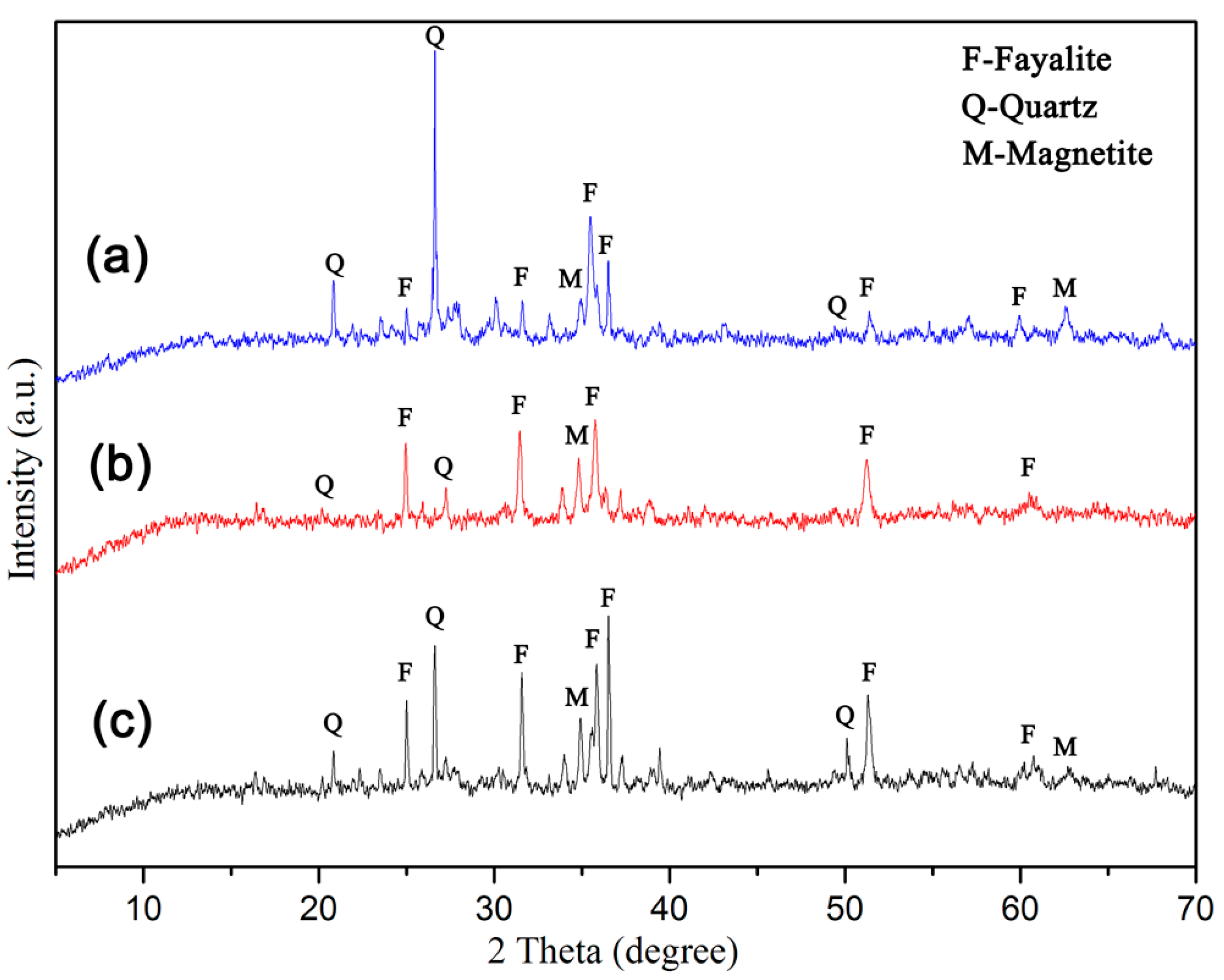
3.4. Microstructural Characterization and Phase Evaluation

The microstructures of the deposit samples at different locations were obtained using a Leica DM4500P polarizing microscope, and the results are shown in Figure 4. As shown in Figure 4, there is a large number of round or elliptical pores inside sample S1 and S2 (Figure 4a,b), while there has a few pores in sample S3 (Figure 4c). The pores in sample S1 (Figure 4b) are not only obvious larger than sample S2 (Figure 4a), but also have many large thin-walled pores. Moreover, there are oriented linear pores only occurs in sample S1 (Figure 4b). The reason for the generation of pores is that limonite ore structure become loose and porous after losing crystal water, then the main component of the reducing gas, carbon monoxide, can be deepened into the limonite ore particles and react with Fe2O3 to form CO2, and those CO2 bubbles become pores in the solidification of deposits. Generally, the combustion efficiency of the pulverized coal is approximately 80–90% [30]. Therefore, the utilization efficiency of coal in present study may be lower because the coal was mixed in the limonite mainly for limonite reduction under lower temperature. When the coal particles trapped inside the deposits were completely burned or reacted with adjacent limonite particles, the remaining vacancies became pores. In addition, the bubbles in the viscosity liquid phase were elongated when the liquid phase flow and the elongated bubbles became oriented pores if the liquid phase solidifies rapidly (Figure 4b). The rapid solidification of the deposits is possible in limonite MRR production. The production must be stopped to remove the deposits if the deposit ring reached a height that affects the normal operation of the rotary kiln, so the external deposit would undergo a rapid cooling process, resulting in rapid solidification of the liquid phase. Sample S3 (Figure 4c) has loose structure and a few pores, indicating that there was less liquid phase formation therein.
Figure 4 shows that the phase composition of deposit samples is basically the same. Besides some independent quartz and limonite granules, the deposits consist mainly of fayalite, glass phase (amorphous silicate) and a small amount of magnetite. As the embedded substrate of magnetite, the irregular-shaped fayalite is the most important phase of the deposits at different locations. As shown in Figure 4, it is clear that the fayalite is the main bonding phase, which connects the dispersed magnetite and glass phase. The glass phase is mainly distributed around the pore or disseminates in fayalite, and it has little intersection with magnetite. Magnetite usually embeds in fayalite with a locally enriched in disseminated form (Figure 4e), some are denser round shape or elliptical agglomerates (Figure 4f). The size of magnetite agglomerates varies greatly, generally between 0.02 to 2 mm. The large magnetite agglomerates have obvious boundary, and pores were left by reduction reaction inside. It is clear that these large magnetite agglomerates were mainly derived from the reduced limonite ore (Figure 4f). The disseminated magnetite agglomerates consist of a large number of spotted worm-like Fe3O4 crystallites, indicating that they were crystallized from liquid phase [31].
The structure of mineral phase of deposit samples were determined by XRD analysis. As illustrated in Figure 5, the crystalline phase of S1, S2 and S3 were fayalite, magnetite and quartz. The peak intensity of S1 is lower than that of S2, indicating it contains more amorphous phase in external deposit. Polarization microscopic images (Figure 4a,b) show the same result. Sample S3 has the same phase composition with S1 and S2, but there was more silica in S3, which is consistent with the results of chemical analysis (Table 4).
According to the above analysis, the process of cooling and crystallization of deposits can be inferred. The internal temperature of the deposit ring decreased as the height of the ring increased, and the liquid phase begins to condense and crystallize. According to their melting point, the phase with the highest melting point in the liquid phase precipitates first, while the other phases precipitated sequentially [31]. Possessing the highest melting point (1597 °C) in the system, magnetite precipitated first in the form of metal minerals phase. The iron silicate phase in the deposits then crystallized as fayalite and encapsulated the precipitated magnetite. The phases with low melting point and poor crystallization ability, and the mixture phases which had no time for crystallization in rapid cooling were wrapped around the fayalite and solidified in form of glass phase. Since the melting point of quartz is 1710 °C, it is not easy for the free quartz particles from the raw materials and coal ash to melt amid the MRR process; however, they are prone to be angular erosive. The eroded quartz particles were embedded randomly in the deposit in the form of monomers (Figure 4d).
Due to the serious negative impact on MRR production of deposits on kiln wall, the phase evaluation and elemental distribution of sample S1 and S2 were determined by SEM-EDS analysis. As shown in Figure 6 and Figure 7, the phase composition of the kiln wall deposit is mainly fayalite (point B) combined with magnetite (point A) and glass phase (amorphous silicate, point C), the same on more microscopic scale comparing with the results of polarizing microscopy. As we can see from Figure 6 and Figure 7, the metal phase is almost entirely Fe3O4 with few impurities. The content of fayalite is basically the same between different deposits. Compared with other two phases, the glass phase composition is complicated. The content of calcium and silicon therein increased significantly, while the iron content decreased, and small amounts of other elements, including magnesium, aluminum and manganese, are also found in the glass phase.
As shown in Figure 8, the EDS elemental mapping testified the same elements distribution. It can be seen from Figure 8 that iron is mainly concentrated in magnetite, and secondly in fayalite. Silicon is mainly concentrated in glass phase, and secondary in fayalite. Aluminum and calcium are mainly concentrated in glass phase, while the content of calcium is significantly higher than other phases. Magnesium and manganese exist in a small amount in fayalite and glass phase. For different local deposits, the distribution characteristics of elements are consistent, which suggests that the same rules are followed during solidification of deposits. In addition, Figure 8 shows that there is a small amount of residual carbon left inside the deposits, indicates that it may maintain a reducing condition inside the deposit during its formation, which benefits the formation of FeO.

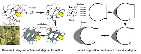
3.5. Mechanism for Deposit Formation

3.5.1. Generation of Wüstite (FeO)

Generally, the reduction reactions of coal are regarded as the combination of direct and indirect reduction reactions [32]. Therefore, the reduction reaction of limonite MRR can be regarded as a combination of direct carbon reduction and carbon monoxide reduction. The amount of coal blended in the iron ore of sintering process is directly related to the FeO content in sintered ore. The FeO content in sintered ore can be greater than 30% when the proportion of coal reaches 7% of the iron ore [33]. The amount of coal mixed in the limonite MRR process is 4–8%, which is equivalent to the sintering process. Limonite was easily over-reduced to form FeO by the residual carbon in deposits when the local temperature is too high. It can be seen that most of iron oxides in deposits existed in the form of FeO (see Table 4).
Studied showed formation of FeO begins at about 900 °C from hematite under reduction condition [34]. Even if the FeO content is only 5%, the liquefaction temperature of the low melting point eutectic liquid phase can be reduced to about 920 °C, and the liquid phase content increases with the increase of FeO content [35]. FeO played a very important role for producing low melting point eutectic liquid phase.

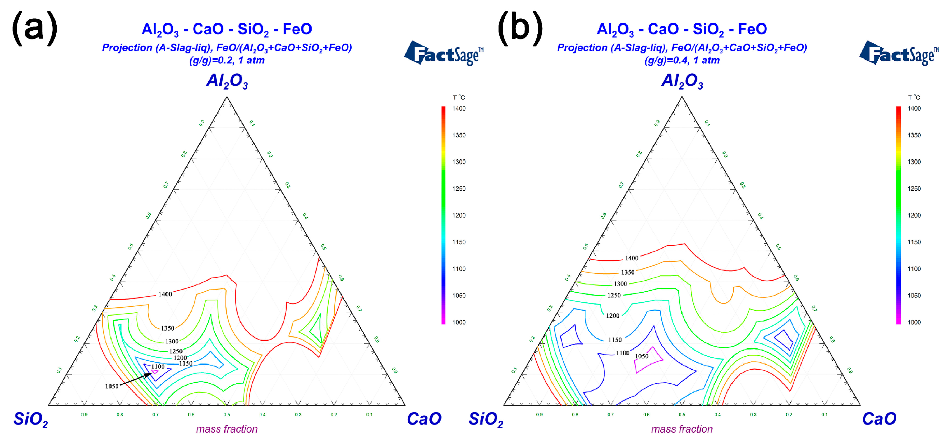
3.5.2. Solid Phase Reaction Process of Al2O3-SiO2-CaO-FeO System

The solid-state reaction occurs at the interface of the two particles and produces a corresponding eutectic liquid phase. The temperature at which the solid phase reaction begins is called the Tamman temperature [36], which is much lower than the melting point of the reactants and the system eutectic temperature. The solid state reaction can occur between limonite particles, coal ash particles, or between limonite and coal ash particles in limonite MRR. The particles below 2 mm of the limonite account for about 5–10% in Xinjiang MRR production, which are in a high activation state because of their high lattice defect and high surface free energy. Moreover, decrystallization water and the transformation of the crystal lattice occurred during the reduction of limonite, which leads to partial particle pulverization and strengthens the occurrence of solid-state reaction. In addition, since the alkalinity of the limonite ore is low, the product of solid-state reaction under reducing atmosphere was mainly iron silicate. The results of phase analysis show that fayalite is the most important phase composition and the most important binder phase of the deposits. Alkali metal oxides and salts are known to act corrosively on refractory brick [37]; moreover, the liquid phase may react and bond with the refractory brick [19,38]. These may be two important reasons for the deposits formed and adhered on kiln wall. The iron silicate phase is mainly composed of fayalite, which can be derived from the direct reaction of FeO and SiO2, or by the reaction of Fe3O4 with SiO2 and CO.
FeO can react with SiO2 to form low melting point eutectic liquid phase contains fayalite, wüstite and silicate melts [39]. Fe3O4, FeO, SiO2 and solid particles are continuously infiltrated and eroded by the eutectic liquid phase, lead to the continuous expansion of the liquid phase region. The phase diagrams of Al2O3-SiO2-CaO-FeO system with different FeO content were plotted by FactSage® 7.2 software to show the effect of the FeO content on the change of liquid phase region and liquefaction temperature. Figure 9a,b displayed the phase diagrams of the content of FeO were 20% and 40%, respectively. As shown in Figure 9, the gap between the adjacent isotherm lines is 50 °C. Figure 9a shows that the liquefaction temperature is less than 1100 °C when the FeO content is 20%, and it can be seen from Figure 9b that the liquid phase areas significantly expanded and the liquefaction temperature dropped below 1050 °C when the FeO content increased to 40%. Obviously, the amount of low melting point eutectic liquid phase increased while the liquefaction temperature decreases significantly as the FeO content increased.

3.5.3. Analysis of the Deposit Formation Mechanism

The fine particles with larger interfacial energy are more likely to coalesce together, because the presence of low melting point eutectic liquid phase which accelerates the diffusion of the fine-grained particle lattice atoms against the bond force at the mutual contact points or contact surfaces. The aggregated particles wrapped by the eutectic liquid phase exhibit a strong diffusion displacement effect under high temperature, prompting more particles to gather and grow up. Moreover, the eutectic liquid phase will continuously keep melting the high-melting solid particles and expanding the range of liquid phase. The eutectic liquid phase mixed with solid particles adheres to the refractory bricks first [19], and adheres layer by layer with the rotation of the rotary kiln to form layer-structured deposit ring on the kiln wall.
The formation process of air duct deposit was that coal ash and limonite ore particles adhere to the duct head by inertial deposition first, and then bonded by a small amount of low melting point eutectic liquid phase. Therefore, the chemical composition ratio of air duct deposit was slightly different from the kiln wall deposits, and has the same phase composition to the kiln wall deposits because it has the same solid-state reaction and crystallization mechanism. Coal ash contains a large amount of SiO2 and Al2O3, both which can further reduce the alkalinity of raw material, then, liquid phase forms more easily and the formation rate of deposit increases.
The residual carbon retains the reducing atmosphere in deposit ring and promotes the formation of FeO. Compared with other compositions, there are more FeO and SiO2 in the deposits. These two compositions are the main factors influencing the generating of eutectic liquid phase as they can significantly lower liquefaction point of the deposit. The schematic diagrams of the formation process of kiln wall deposits and the impact deposition mechanism of air duct deposit were shown in Figure 10 and Figure 11, respectively.
Influenced by limonite and coal composition, reaction atmosphere and coal ash dosage, the large amount of liquid phase formed amid the MRR production and the formation of deposit is unavoidable. However, the formation rate of the deposit can be significantly slowed down by restraining the formation of low melting point eutectic liquid phase and the over-reduction of limonite, and by reducing the content of coal ash. In the commercial practice in Xinjiang, by reducing the amount of fine-grained limonite and the coal mixed in limonite, or using low-ash coal, the deposit formation rate was reduced to 1/3 to 1/2 of the original value. By moving gas burner timely, the deposits on the kiln wall can periodically be cracked and collapsed, and the non-stop operation time of the rotary kiln MRR system can be significantly prolonged up to 2 months or longer.

4. Conclusions

In this study, the deposits in gas-fired rotary kiln for limonite magnetic-reduction roasting were characterized and the formation mechanism was investigated. The key factors of the deposit formation for the limonite MRR production were clarified.
The deposit on the kiln wall is mainly formed by the solid phase reaction of the fine limonite and coal ash, which generates low melting point eutectic liquid phase adhered granular limonite and contributes to the grown of the deposit. The air duct deposit is mainly caused by the impact deposition of fine particles in flue gas thereon, which results in solid state reaction and liquid phase formation at high temperature, and bonded under the action of the viscous liquid phase.
FeO and SiO2 are the main factor for generating low melting point eutectic liquid phase. The liquid phase infiltrates and erodes the surrounding solid materials, which results in the continuous expansion of the liquid phase range and causes the solid particles to grow close together. This is the main factor for the rapid growth of the deposit.
The main phase of deposits collected at different locations is mainly fayalite, glass phase, magnetite and a small amount of quartz and limonite. Fayalite, the most important binder phase, accounts for the formation and adhesion of deposits.
According to the deposit formation mechanism of the limonite MRR production, inhibiting the formation of eutectic liquid phase may benefit the slowing down of the development of deposits, and the possible approaches are reducing fine-grained limonite into the kiln, matching the coal blending amount and reducing coal ash into the kiln by using low-ash coal.

Author Contributions

Conceptualization, X.F.; methodology, Y.S.; investigation, X.F. and Z.C.; resources, L.H.; writing-original draft, X.F.; writing-review & editing, X.F. and X.X.; project administration, Z.C.; interpretation of data, L.H.; approved the final version, X.F.

Funding

This research was funded by the 12th five-year National Key Technology Research and Development Program of the Science and Technology of China (No. 2015BAB03B06).

Acknowledgments

The authors wish to thank the colleagues of the Changsha Research Institute of Mining and Metallurgy Co. Ltd for their administrative support and helpful assistance with experiment.

Conflicts of Interest

The authors declare no conflict of interest.

References

  1. Wu, F.; Cao, Z.; Wang, S.; Zhong, H. Novel and green metallurgical technique of comprehensive utilization of refractory limonite ores. J. Clean. Prod. 2018, 171, 831–843. [Google Scholar] [CrossRef]
  2. Liu, G.-S.; Strezovb, V.; Lucas, J.A.; Wibberley, L.J. Thermal investigations of direct iron ore reduction with coal. Thermochim. Acta 2004, 410, 133–140. [Google Scholar] [CrossRef]
  3. Luo, L.; Zhang, J.; Yu, Y. Recovering limonite from Australia iron ores by flocculation-high intensity magnetic separation. J. Cent. South Univ. Technol. 2005, 12, 682–687. [Google Scholar] [CrossRef]
  4. Chen, W.; Liu, X.; Peng, Z.; Wang, Q. Recovery of Huangmei limonite by flash magnetic roasting technique. In Proceedings of the 3rd International Symposium on High-Temperature Metallurgical Processing, Hoboken, NJ, USA, 17 March 2012; pp. 49–58. [Google Scholar]
  5. Rath, S.S.; Dhawan, N.; Rao, D.S.; Das, B.; Mishra, B.K. Beneficiation studies of a difficult to treat iron ore using conventional and microwave roasting. Powder Technol. 2016, 301, 1016–1024. [Google Scholar] [CrossRef]
  6. Nasr, M.; Youssef, M.A. Optimization of magnetizing reduction and magnetic separation of iron ores by experimental design. ISIJ Int. 1996, 36, 631–639. [Google Scholar] [CrossRef]
  7. Youssef, M.A.; Morsi, M.B. Reduction roast and magnetic separation of oxidized iron ores for the production of blast furnace feed. Can. Metall. Q. 2013, 37, 419–428. [Google Scholar] [CrossRef]
  8. Li, C.; Sun, H.; Bai, J.; Li, L. Innovative methodology for comprehensive utilization of iron ore tailings: Part 1. The recovery of iron from iron ore tailings using magnetic separation after magnetizing roasting. J. Hazard. Mater. 2010, 174, 71–77. [Google Scholar] [CrossRef]
  9. Rath, S.S.; Sahoo, H.; Dhawan, N.; Rao, D.S.; Das, B.; Mishra, B.K. Optimal recovery of iron values from a low grade iron ore using reduction roasting and magnetic separation. Sep. Sci. Technol. 2014, 49, 1927–1936. [Google Scholar] [CrossRef]
  10. Shuai, X.; Zhang, Y.; Xu, H.; Zhou, H.; Qi, Y. Magnetic roasting of limonite of low grade. J. Iron Steel Res. 2015, 27, 8–12. (In Chinese) [Google Scholar]
  11. Ponomar, V.P.; Dudchenko, N.O.; Brik, A.B. Synthesis of magnetite powder from the mixture consisting of siderite and hematite iron ores. Miner. Eng. 2018, 122, 277–284. [Google Scholar] [CrossRef]
  12. Zhu, Q.; Li, H. Status quo and development prospect of magnetizing roasting via fluidized bed for low grade iron ore. CIESC J. 2014, 65, 2437–2442. (In Chinese) [Google Scholar] [CrossRef]
  13. Yan, A.; Chai, T.; Yu, W.; Xu, Z. Multi-objective evaluation-based hybrid intelligent control optimization for shaft furnace roasting process. Control Eng. Pract. 2012, 20, 857–868. [Google Scholar] [CrossRef]
  14. Wang, Q.; Chen, W.; Yu, Y.; Yan, X.; Liu, X. Test research on the flash magnetization roasting technology for complex and refractory iron ore. Metal Mine 2009, 402, 73–76. (In Chinese) [Google Scholar]
  15. Li, Y.; Zhu, T. Recovery of low grade haematite via fluidised bed magnetising roasting: Investigation of magnetic properties and liberation characteristics. Ironmak. Steelmak. 2013, 39, 112–120. [Google Scholar] [CrossRef]
  16. Liu, X.; Yu, Y.; Hong, Z.; Peng, Z.; Li, J.; Zhao, Q. Development and application of packaged technology for flash(fluidization) magnetizing roasting of refractory weakly magnetic iron ore. Mining Metall. Eng. 2017, 37, 40–45. (In Chinese) [Google Scholar] [CrossRef]
  17. Zhang, X.; Han, Y.; Sun, Y.; Li, Y. Innovative utilization of refractory iron ore via suspension magnetization roasting: A pilot-scale study. Powder Technol. 2019, 352, 16–24. [Google Scholar] [CrossRef]
  18. Fu, X.; Mao, Y.; Xue, S. Study on deposit formation and prevention control of large industrial magnetized roasting rotary kiln. Nonferrous Met. (Mineral Processing Section) 2013, s1, 236–239. (In Chinese) [Google Scholar]
  19. Wang, S.; Guo, Y.; Fan, J.; He, Y.; Jiang, T.; Chen, F.; Zheng, F.; Yang, L. Initial stage of deposit formation process in a coal fired grate-rotary kiln for iron ore pellet production. Fuel Process. Technol. 2018, 175, 54–63. [Google Scholar] [CrossRef]
  20. Wang, S.; Guo, Y.; Fan, J.; Jiang, T.; Chen, F.; Zheng, F.; Yang, L. Deposits in a coal fired grate-kiln plant for hematite pellet production: Characterization and primary formation mechanisms. Powder Technol. 2018, 333, 122–137. [Google Scholar] [CrossRef]
  21. Guo, Y.-F.; Wang, S.; He, Y.; Jiang, T.; Chen, F.; Zheng, F.-Q. Deposit formation mechanisms in a pulverized coal fired grate for hematite pellet production. Fuel Process. Technol. 2017, 161, 33–40. [Google Scholar] [CrossRef]
  22. Zhong, Q.; Yang, Y.; Jiang, T.; Li, Q.; Xu, B. Effect of coal ash on ring behavior of iron-ore pellet powder in kiln. Powder Technol. 2018, 323, 195–202. [Google Scholar] [CrossRef]
  23. Jiang, T.; He, G.; Gan, M.; Li, G.; Fan, X.; Yuan, L. Forming mechanism of rings in rotary-Kiln for forming mechanism of rings in rotary-kiln for oxidized pellet. J. Iron Steel Res. Int. 2009, 16, 292–297. [Google Scholar]
  24. Stjernberg, J.; Jonsson, C.Y.C.; Wiinikka, H.; Lindblom, B.; Boström, D.; Öhman, M. Deposit formation in a grate–kiln plant for iron-ore pellet production. Part 2: Characterization of deposits. Energy Fuels 2013, 27, 6171–6184. [Google Scholar] [CrossRef]
  25. Zheng, G. Chemical analysis method standards and proficiency testing of laboratory for iron ore. Metall. Anal. 2015, 35, 37–44. (In Chinese) [Google Scholar]
  26. Wu, X.; Ji, H.; Dai, B.; Zhang, L. Xinjiang lignite ash slagging and flowability under the weak reducing environment at 1300 °C—A new method to quantify slag flow velocity and its correlation with slag properties. Fuel Process. Technol. 2018, 171, 173–182. [Google Scholar] [CrossRef]
  27. Zhang, Z.; Wu, X.; Zhou, T.; Chen, Y.; Hou, N.; Piao, G.; Kobayashi, N.; Itaya, Y.; Mori, S. The effect of iron-bearing mineral melting behavior on ash deposition during coal combustion. Proc. Combust. Inst. 2011, 33, 2853–2861. [Google Scholar] [CrossRef]
  28. Baxter, L.L.; DeSollart, R.W. A mechanistic description of ash deposition during pulverized coal combustion predictions compared with observations. Fuel 1993, 72, 1411–1418. [Google Scholar] [CrossRef]
  29. Baxter, L.L. Ash deposition during biomass and coal combustion a mechanistic approach. Biomass Bioenerg. 1993, 4, 85–102. [Google Scholar] [CrossRef]
  30. Ishii, K. (Ed.) Advanced Pulverized Coal Injection Technology and Blast Furnace Operation; Elsevier: Amsterdam, The Netherlands, 2000. [Google Scholar]
  31. Chen, Y.; Chen, R. Microstructure of Sinter and Pellet; Central South University Press: Changsha, China, 2011. (In Chinese) [Google Scholar]
  32. Ma, B.; Wang, C.; Yang, W.; Yin, F.; Chen, Y. Screening and reduction roasting of limonitic laterite and ammonia-carbonate leaching of nickel–cobalt to produce a high-grade iron concentrate. Miner. Eng. 2013, 50, 106–113. [Google Scholar] [CrossRef]
  33. Zhang, H. Theory and Technology of Sintered Pellets; Chemical Industry Press: Beijing, China, 2015. (In Chinese) [Google Scholar]
  34. Zeng, T.; Helble, J.J.; Bool, L.E.; Sarofim, A.F. Iron transformations during combustion of Pittsburgh No. 8 coal. Fuel 2009, 88, 566–572. [Google Scholar] [CrossRef]
  35. Wang, S.; Guo, Y.; Chen, F.; He, Y.; Jiang, T.; Zheng, F. Combustion reaction of pulverized coal on the deposit formation in the kiln for iron ore pellet production. Energy Fuels 2016, 30, 6123–6131. [Google Scholar] [CrossRef]
  36. Merkle, R.; Maier, J. On the tammann-rule. Z. Anorg. Allg. Chem. 2005, 631, 1163–1166. [Google Scholar] [CrossRef]
  37. Dahotre, N.B.; Kadolkar, P.; Shah, S. Refractory ceramic coatings: Processes, systems and wettability/adhesion. Surf. Interface Anal. 2001, 31, 659–672. [Google Scholar] [CrossRef]
  38. Stjernberg, J.; Ion, J.C.; Antti, M.-L.; Nordin, L.-O.; Lindblom, B.; Odén, M. Extended studies of degradation mechanisms in the refractory lining of a rotary kiln for iron ore pellet production. J. Eur. Ceram. Soc. 2012, 32, 1519–1528. [Google Scholar] [CrossRef]
  39. Huffman, G.P.; Huggins, F.E.; Dunmyre, G.R. Investigation of the high-temperature behaviour of coal ash in reducing and oxidizing atmospheres. Fuel 1981, 60, 585–597. [Google Scholar] [CrossRef]
Figure 1. Schematic diagram of sampling locations of different deposits.
Metals 09 00764 g001
Figure 2. Digital photos of internal view of the Φ 4 m × 60 m limonite magnetization reduction roasting (MRR) rotary kiln: (a) without deposit; (b) with serious deposits; (c) cross section schematic of the kiln.
Metals 09 00764 g002
Figure 3. Digital photos of deposit samples collected from different locations in rotary kiln: (a) S1 with adhered limonite granules on surface; (b) characteristics of the longitudinal section of S1; (c) characteristics of the longitudinal section of S2; (d) appearance characteristics of S3.
Metals 09 00764 g003
Figure 4. Polarized microscopic images of (a) internal deposit (S2); (b) external deposit (S1); (c) air duct deposit (S3); (d) deposit containing independent quartz; (e) infiltrated magnetite phase; (f) granular magnetite phase.
Metals 09 00764 g004
Figure 5. X-ray diffraction (XRD) patterns of: (a) air duct deposit (S3); (b) external deposit on kiln wall (S1); (c) internal deposit on kiln wall (S2).
Metals 09 00764 g005
Figure 6. Scanning electron microscopy (SEM)-energy dispersive spectra (EDS) analysis of external deposit sample (S1).
Metals 09 00764 g006
Figure 7. SEM-EDS analysis of internal deposit sample (S2).
Metals 09 00764 g007
Figure 8. EDS elemental mapping of deposit sample.
Metals 09 00764 g008
Figure 9. Effects on liquid areas of Al2O3-SiO2-CaO-FeO phase diagrams by FeO of: (a) FeO/(Al2O3-SiO2-CaO-FeO) (g/g) = 0.2; (b) FeO/(Al2O3-SiO2-CaO-FeO) (g/g) = 0.4.
Metals 09 00764 g009
Figure 10. Schematic diagram of kiln wall deposit formation.
Metals 09 00764 g010
Figure 11. Impact deposition mechanism of air duct deposit.
Metals 09 00764 g011
Table 1. Chemical Compositions and Ignition Loss of Limonite Ore (wt%).
Total FeFeOFe2O3SiO2Al2O3CaOMgOMnOK2ONa2OSIg
35.8510.239.9218.893.792.222.421.861.020.0920.2615.8
Table 2. Property of the Coal (wt%).
Moisture/%Ash/%Volatile Matter/%Fixed Carbon/%Qgr/(MJ·Kg−1)Coking Properties (1–8)
2.310.2830.0257.3228.632
Table 3. Chemical Compositions of Coal Ash (wt%).
SiO2Fe2O3Al2O3CaOMgOK2ONa2O
55.429.8120.182.682.83.560.42
Table 4. Chemical compositions of deposit samples (wt%).
Deposit SampleComp. FeOTFeFeOFe2O3SiO2Al2O3CaOMgOMnOK2ONa2OS
S1max42.5144.898.6629.576.522.512.692.282.050.150.31
min39.7840.169.9330.327.642.822.022.091.930.220.27
S2max40.6741.359.5430.187.292.912.251.812.080.210.27
min38.8038.3211.8131.028.002.702.022.052.200.240.13
S3-34.5337.226.8233.429.284.412.401.772.200.320.18

