Abstract
In order to study the flow field, temperature field, and inclusion removal in a new induction heating tundish with bent channels, a three-dimensional (3D) transient mathematical model is established. The effects of both the channel radius and heating power on the multi-physical field and inclusion removal in the bent channels’ induction heating tundish are investigated. The results show that the tundish with the channel radius of 3 m shows better flow characteristics than those with the channel radii of 4 m and 2 m. With the increase of channel length, the heating efficiency increases at first, and then decreases, while the radius of 3 m is the best one for heating efficiency. After all the inclusions are placed into the tundish, the radii of 3 m and 2 m show good efficiency regarding inclusion removal, while it is poor when the radius is 4 m. Therefore, 3 m is the optimal radius of the channel in this work. Under the optimal channel radius, the heating power of 800 kW seems better than those of 600 kW and 1000 kW on flow characteristics control in the tundish. The temperature in the receiving chamber rises gradually and distributes quite uniformly with the increasing heating power, and the removal rate of inclusions increases with the increasing heating power.
1. Introduction
For a long time, there has been agreement that steady casting with low superheat and constant temperature is critical to improve the quality of casting slab, raise the efficiency of continuous casting production, and stabilize the continuous casting [1,2,3,4]. During the continuous casting process, the steady casting with low superheat and constant temperature will be under an unfavorable condition, which is the temperature drop of molten steel due to the heat losses caused by both the thermal radiation on the surface of the liquid steel and the heat absorption of the tundish wall, especially the inevitable great temperature drop during the initial casting stage, period of changing the steel ladle, and final casting stage. As a result, it will affect the quality of the casting slab [5]. Recently, induction heating tundish has been presented to improve the temperature distribution of molten steel and keep the temperature unchanged in continuous casting tundish.
Yoshii et al. [6]. developed an induction heating tundish with a single channel in 1984. It contained a refractory channel inside the tundish and a coil that was used to generate magnetic flux. The value of the supplied electric power depended on the amount of the liquid steel in the tundish, and the liquid steel was heated when it passed through the channel. Therefore, the purpose of compensating the temperature drop of the liquid steel was realized. Umbrashko et al. [7] experimented and numerically simulated the fluid flow in an induction furnace in 2006. In the experiment, they found four symmetrical eddies in the induction furnace. In the numerical simulation, the commercial software ANSYS and FLUENT was used to simulate the electromagnetic field distribution and flow field, respectively. In comparison with the experimental results, it was found that the simulation could well predict the fluid flow in the furnace. The flow pattern in the simulation matched well with that in the experiment, and the drastic fluctuation of the turbulence energy was also well predicted. Wang et al. [8] conducted a numerical simulation on the electromagnetic field, flow field, and heat transfer in a channel-type induction heating tundish. The results showed that Joule heating could effectively compensate heat loss for molten steel. The induction heating of the continuous casting tundish could make the temperature distribution more uniform. Yue et al. [9] carried out numerical simulation as well as industrial experiment to study the magnetic flow and heat transfer in a twin-channel induction heating tundish. They found that there was a significant effect of electromagnetic force on the molten steel flow in the tundish, and that the flow pattern varied with Joule heating, while the electromagnetic force had little effect on it. Yang et al. [10,11] established physical and mathematical models to investigate electromagnetic phenomena, flow field, and heat transfer in a channel type induction heating tundish. Results showed that in the induction heating channels, the electromagnetic field, current field, electromagnetic force, and heating power are the greatest. There is spiral flow in the channel caused by electromagnetic force, and based on Joule heating, the temperature increase of liquid steel is 12 K throughout the channel. Wang et al. [12] studied the inclusions removal and their motion behaviors in a tundish with induction heating by building a three-dimensional (3D) transient mathematical model. It was observed that the inclusion removal rate became higher when the induction heating power was increased. The calculation of the removal rate should take collision growth into account. This study was based on a relatively simple tundish structure, and the channel was straight. The authors have proposed a new type induction heating tundish with curved channels, which can solve the problem of low heating efficiency and inclusion removal of the traditional induction heating tundish with straight channels [13]. Furthermore, the motion and removal of inclusions in new and traditional tundishes were compared. However, the effect of process operating parameters on the flow field, temperature field, and inclusion removal in the bent-channel tundish is still not clear.
The analysis for the residence time distribution (RTD) curve is one of the most important and effective approaches to study the melt flow in the tundish. Nonetheless, the little literature that has been reported has concentrated on the RTD curve in the induction heating tundish. Moreover, the channel radius and heating power are two important parameters of the new induction heating tundish with bent channels. In the present work, a 3D transient mathematical model was established to research the effects of both the channel radius and heating power on the flow field, temperature field, RTD curve, and inclusion removal in the bent-channel induction heating tundish.
2. Mathematical Model
2.1. Geometric Model
Figure 1a shows the geometrical model of the bent-channel tundish with induction heating. The model is established according to the actual dimensions, and it is a single-strand induction heating tundish. The channels connect the receiving chamber and the discharging chamber. More details about the geometric model can be found in our previous work [13].
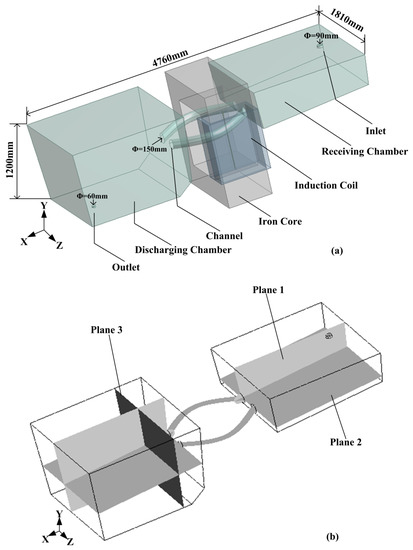
Figure 1.
(a) Geometrical model of the bent channels’ induction heating tundish. (b) Planes used in the mathematical model.
2.2. Control Equations
The electromagnetic field is calculated by using the Maxwell equations; the flow field is calculated by jointly using the continuity equation, the Navier–Stokes equation, and the k-ε model; the energy equation is resolved to confirm the temperature field; and the motion behaviors of inclusions are investigated using the motion equation of inclusions [13].
2.2.1. Electromagnetic Model
The Maxwell equations of the electromagnetic field are described as follows:
where is the electric flux density, q is the electric charge density, is the electric field intensity, is the magnetic flux density, t is time, is the magnetic field intensity, and is the induced current density [14,15,16].
2.2.2. Fluid Dynamics Model
The continuity equation and the Navier–Stokes equation are:
where ρ is the density of the liquid steel, and it is the function of temperature (), is the velocity of the liquid steel, p is the static pressure, is the gravitational acceleration vector [17,18], µeff is the effective viscosity [19], and is the volumetric force [8,9].
The standard k-ε model [20,21] is:
where Gk represents the turbulence energy under the mean velocity gradient, and is decided by:
The effective viscosity is:
where μ is the dynamic viscosity, and μt is the turbulent viscosity. C1, C2, Cμ, σk, and σε are constants given by Launder and Spalding: C1 = 1.44, C2 = 1.92, Cμ = 0.09, σk = 1.0, and σε = 1.3.
The scale transport equation is used to simulate the tracer dispersion:
A dimensionless scalar φ is released at the tundish inlet, the value of the scalar remains the same throughout the calculation, Sct is the turbulence Schmidt number, and Dϕ is the kinematic diffusivity of scalar in molten steel [22,23,24,25].
2.2.3. RTD Curve Model
The flow of molten steel in the tundish was evaluated through the RTD curve. Normally, the flow of molten steel in the tundish is divided into the plug flow, mixed flow, and dead volumes. In the present work, the three volumes are calculated by the following equations [24]:
where Vp/V, Vm/V, and Vd/V are the fractions of the plug flow, mixed flow, and dead volume, respectively; V is the tundish volume; and θmin is the dimensionless minimum resident time. The term Qa/Q is the area under the dimensionless RTD curve θ = 0 to 2, and represents the fractional volumetric flow rate through the active region; is the dimensionless mean residence time.
In order to obtain a good flow pattern, it is important to ensure that the tundish has a minimum dead volume, large ratio of plug to dead volume, surface-directed flow, quiet slag layer, and suitable mixing zone [25,26].
2.2.4. Heat Transfer Model
The energy equation:
where λ is the heat transfer coefficient of the liquid steel, cp is the specific heat at the constant pressure of the liquid steel, ST is the viscosity dissipation factor, and QJ is the joule heat generated by the electromagnetic induction [27,28].
2.2.5. Motion Equations of Inclusion
The motion equations of inclusion include eight forces. They are electromagnetic pressure, thermophoretic, gravity, buoyancy, drag, lift, added mass, and Brownian forces, and the collision and coalescence of inclusions are also considered. More details can be found in our previous work [13].
2.3. Boundary Conditions
In this paper, the single-phase alternating current is loaded to the channel induction coil. The frequency is 50 Hz. The tundish free surface is zero shear stress. The other walls are set as a no-slip boundary condition. The standard near-wall functions are used to capture gradient changes accurately. Both the free surface and walls for the defined scalar are in zero-flux conditions [22,23,24,25].
Inclusions would collide and grow up while moving within the tundish. Some inclusions float up to the liquid steel surface subsequently to being absorbed by the tundish slag, while other inclusions are absorbed by the lining solid surfaces. The motion of the inclusions had no effect on the liquid steel flow. To simplify the calculation, it is assumed that the inclusions are spherical solids, and each inclusion moves alone until a collision with another inclusion occurs. Then, the two inclusions quickly coalesce together to produce a new bigger one. An inclusion would be absorbed by the tundish slag or the lining solid surfaces if the corresponding velocity was lower than a threshold; otherwise, it would rebound back into the liquid, with 40% of the momentum lost. More details of the boundary conditions can be found in previous works [12,13,29,30,31].
The electromagnetic field is calculated by the finite element method, which is based on ANSYS 14.0, and the molten steel flow and temperature distribution are solved by the finite element method of FLUENT 14.0 [32]. The inclusion motion equation is calculated by the DPM (discrete particle method) model of FLUENT [8,9,13].
3. Results and Discussion
3.1. Model Validation
In the present work, the industrial test temperature data of a one-strand slab tundish with an induction heating power of 800 kW are used to validate the mathematical model of the tundish with channel-type induction heating. The temperature data are measured by the continuous temperature measuring device near the tundish stopper. The mathematical model is built on the same geometric dimensions, current, and frequency as the actual tundish. Figure 2 displays the comparison of temperature increase between the experimental and calculation results. The calculation results have good consistency with the experiment results. So, the present mathematical model can be used to investigate the induction heating tundish, and the mathematical model for inclusion removal has already been validated in our previous work [13].
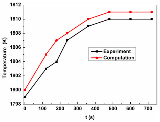
Figure 2.
Comparison of the temperature increases between the experimental and calculation results.
3.2. Effect of Channel Radius on New Tundish
Three different channel radii are chosen to study their effects on the fluid flow, heat transfer, and inclusion removal of the new tundish, while the distance between the receiving chamber and discharging chamber remains the same. Also, the distances between the endpoints of the two channels on the receiving and discharging chambers are identical.
3.2.1. Flow Field
Figure 3 shows the flow fields under different channel radii with 800-kW heating power. With the radius of 4 m, the molten steel flows into the receiving chamber by the ladle shroud nozzle and is heated by the joule heat when flowing through the channels. After the two liquid steel streams flow out from the channels, they keep moving a certain distance, and then converge with small impact force due to the relatively small radian. Therefore, the flow field in the discharging chamber contains two large vortexes, which are not conducive to realize steady casting and remove the inclusions. In addition, the liquid steel will strongly impact the front wall of the discharging chamber, and the refractory erosion may happen. With the channel radius of 3 m, once the two molten steel streams are flowing out of the channels, they converge at first; then, the confluent fluid moves upwards under the effect of the density difference, and finally flows out of the tundish. The confluent fluid plays a stirring role in the discharging chamber and increases the inclusions collision-growth phenomena, which is beneficial to remove inclusions. In addition, the confluent fluid can offset both the upward and forward impact forces, which weakens both the impact on the front wall and the slag/steel interface [13]. When the channel radius is 2 m, the radian is so large that the impact force of the confluent fluid increases greatly and causes obvious chaotic flow in the discharging chamber. So, the flow field in the discharging chamber is worsened. Meanwhile, the upward force is so large that slag entrapment may occur easily. On the whole, 3 m is the optimal channel radius for steady casting in this tundish.
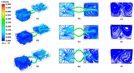
Figure 3.
Flow fields under different channel radii with 800-kW heating power. (a) In a tundish with channels of 4-m radius. (b) In a cross-section (at plane 2) of a tundish with channels of 4-m radius. (c) In a cross-section (at plane 3) of a discharging chamber in a tundish with channels of 4-m radius. (d) In a tundish with channels of 3-m radius. (e) In a cross-section (at plane 2) of a tundish with channels of 3-m radius. (f) In a cross-section (at plane 3) of a discharging chamber in a tundish with channels of 3-m radius. (g) In a tundish with channels of 2-m radius. (h) In a cross-section (at plane 2) of a tundish with channels of 2-m radius. (i) In a cross-section (at plane 3) of a discharging chamber in a tundish with channels of 2-m radius.
3.2.2. Temperature Field
Figure 4 shows the temperature fields at plane 1 under different channel radii with 800-kW heating power. Figure 5 presents the outlet temperature of the tundish under different channel radii with 800-kW heating power. As shown in Figure 4, for each channel radius, the temperature distribution is uniform in the discharging chamber, and the temperature difference is no more than 4 K. When the radius is 4 m, the temperature in the discharging chamber is lower than that with the radius of 3 m. This is because the channel length at the radius of 4 m is shorter, and the liquid steel is heated by a shorter period. It can also be seen from Figure 4 that when the radius is 2 m, the temperature in the discharging chamber is lower than that with the radius of 3 m. As shown in Figure 5, the outlet temperature increases at first, and then decreases with the increasing radius. This indicates that the heating efficiency of the new tundish does not always increase with the increase of channel length: there is an optimal value. Therefore, the channel radius of 3 m shows the best heating efficiency in the present work. However, the reason why the outlet temperature increases at first and then decreases needs further study.
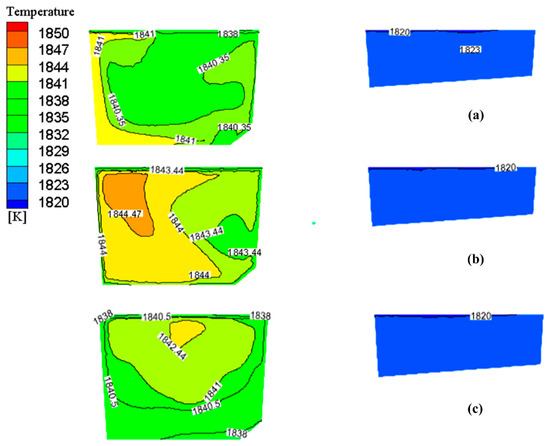
Figure 4.
Temperature fields at plane 1 under different channel radii with 800-kW heating power. (a) 4 m. (b) 3 m. (c) 2 m.
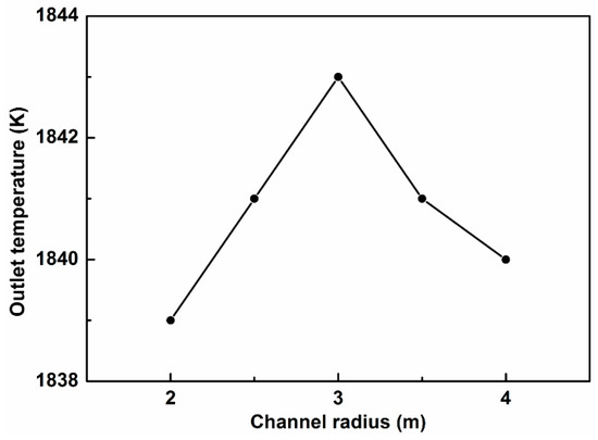
Figure 5.
Outlet temperature of the tundish under different channel radii with 800-kW heating power.
3.2.3. RTD Curve
Figure 6 shows the RTD curves under different channel radii with 800-kW heating power. Table 1 presents the flow characteristics in the new tundish under different channel radii with 800-kW heating power. It can be seen that with the channel radius of 2 m, the ratio of plug to dead volume is the biggest, and the dead volume is the smallest. However, as described above (Figure 3), there exists obvious chaotic flow and slag/steel interface fluctuation in the discharging chamber at the channel radius of 2 m, which is unfavorable to the inclusion control. So, the channel radius of 2 m is poor on the flow control. Compared with the channel radius of 4 m, the channel radius of 3 m has bigger plug volume and ratio of plug to dead volume, so the latter is more efficient regarding controlling the flow than the former. Therefore, the channel radius of 3 m is the best one for flow control among the three channel radii.
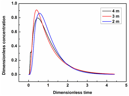
Figure 6.
Residence time distribution (RTD) curves under different channel radii with 800-kW heating power.

Table 1.
Flow characteristics under different channel radii with 800-kW heating power.
3.2.4. Turbulence Intensity
Figure 7 shows the turbulence intensities of the vertical section at plane 1 in the tundish under different channel radii with 800-kW heating power. Figure 8 presents the turbulence intensities of the cross-section at plane 2 in the tundish under different channel radii with 800-kW heating power. It can be seen from Figure 7 that the turbulence intensities in the discharging chambers at the radii of 3 m and 2 m distribute more evenly than that at the radii of 4 m. This is because the two large vortexes make the flow field in the discharging chamber chaotic when the radius is 4 m (Figure 3). As shown in Figure 8, the turbulence intensities in the channels at the radius of 3 m are larger than those at the radii of 4 m and 2 m, so the former is more favorable for the collision-growth of the inclusions and the improvement of the inclusions’ removal.
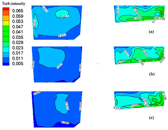
Figure 7.
Turbulence intensities of a vertical section at plane 1 in the tundish under different channel radii with 800-kW heating power. (a) 4 m. (b) 3 m. (c) 2 m.
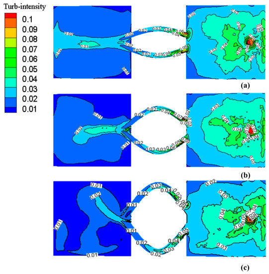
Figure 8.
Turbulence intensities of a cross-section at plane 2 in the tundish under different channel radii with 800-kW heating power. (a) 4 m. (b) 3 m. (c) 2 m.
3.2.5. Inclusion Removal Rate
In this work, seven lower-sized inclusions are selected to describe the inclusion removal, considering that the induction heating technology is focused on lower-sized inclusion removal. The inclusion diameters are 1 μm, 2 μm, 5 μm, 10 μm, 20 μm, 30 μm, and 50 μm. Figure 9a shows the removal rates of inclusions under different channel radii with 800-kW heating power. The inclusions of each size are released respectively at the tundish inlet. For each size, the inclusion removal rates under the channel radii of 3 m and 2 m are much higher than that under the radius of 4 m. There is also a small difference in the inclusion removal between the radii of 3 m and 2 m. After all, the inclusions are placed into the tundish; the same phenomenon as the case for each size released into the tundish can also be seen in Figure 9b. The reason is that the turbulence intensities in the discharging chambers at the radii of 3 m and 2 m distribute more evenly than that at the radii of 4 m (Figure 8), so the former are favorable for the inclusions’ removal. The turbulence intensities in the channels at the radius of 3 m are larger than those at the radii of 4 m and 2 m, so the 3-m channels are more favorable for the collision growth of the inclusions and improvement of the inclusions’ removal. However, the length of the 2-m channel is longer than that of the 3-m channel, so the inclusions removal rate with the channel radius of 2 m is a little higher than that with the channel radius of 3 m.
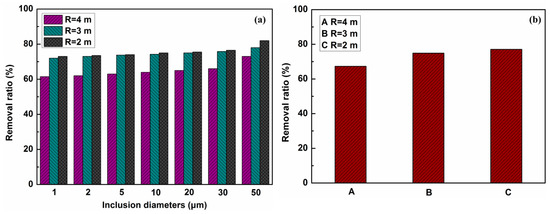
Figure 9.
Removal rates of inclusions under different channel radii with 800-kW heating power. (a) Each size. (b) All sizes.
Overall, the optimal channel radius for the flow field, temperature field, and inclusions removal is 3 m in the present work.
3.3. Effect of Heating Power on New Tundish
Under the optimal channel radius of 3 m in this tundish, the effect of different heating powers on the bent-channel tundish has been investigated.
3.3.1. Flow Field
Figure 10 displays the flow fields in the new tundish with different heating powers. It can be seen that without induction heating, flow characteristics similar to induction heating are formed under the effect of heat loss and the junction of the two flows, while the convection intensity is obviously insufficient. When the heating powers are 600 kW and 800 kW, the flow regularities in the discharging chambers are similar and described above (Figure 3d), while the convection intensity of 800 kW is stronger [8]. However, with the heating power of 1000 kW, the flow field in the discharging chamber becomes chaotic because of the overlarge convection force, which is negative for the steady casting with low superheat. Therefore, the heating power for this tundish shall not be too large.
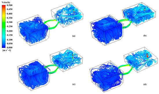
Figure 10.
Flow fields with different heating powers. (a) Without induction heating. (b) 600 kW. (c) 800 kW. (d) 1000 kW.
3.3.2. Temperature Field
Figure 11 presents the temperature fields at plane 1 in the tundish with different heating powers. It can be seen that the net drop in temperature in the tundish is about 7 K without induction heating. Then, the molten steel temperature of the discharging chamber rises with the increasing heating power, and the temperature fields are uniform. This is because the junction of the two flows plays a stirring role in the discharging chamber, which makes the temperature distribution in the discharging chamber uniform. However, when the heating power is 1000 kW, the temperature field in the discharging chamber becomes nonuniform, and the temperature difference is large. The reason is that the flow field in the discharging chamber is chaotic due to the overlarge convection force (Figure 10d).
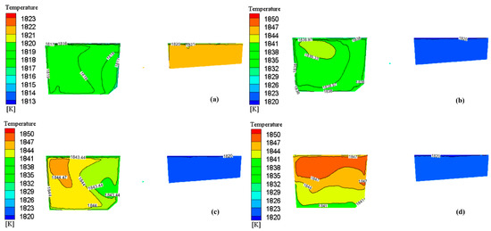
Figure 11.
Temperature fields at plane 1 with different heating powers. (a) Without induction heating. (b) 600 kW. (c) 800 kW. (d) 1000 kW.
3.3.3. RTD Curve
Figure 12 shows the RTD curves in the tundish with different heating powers. Table 2 displays the flow characteristics in the tundish with different heating powers. It can be seen that the tundish with the heating powers of 600 kW and 800 kW show better flow characteristics than that without induction heating. Compared with 600-kW heating power, the heating power of 800 kW has a longer resident time, smaller dead volume, and bigger ratio of plug to dead volume. So, the latter is more efficient regarding controlling the flow than the former. The reason is that with the increasing heating power, the junction of the two flows is stronger, and the temperature of them is higher [8]. Therefore, the convection flow is enhanced. However, when the heating power is increased to 1000 kW, the residence time becomes shorter, the dead volume turns bigger, and the ratio of the plug to dead volume becomes much smaller. It indicates that the flow characteristics in the tundish will be worsened if the heating power is too large. The reason is that with the increasing heating power, the convection force is too large. Then, the flow field becomes chaotic in the discharging chamber, which is unfavorable for the steady casting with low superheat (Figure 10d).
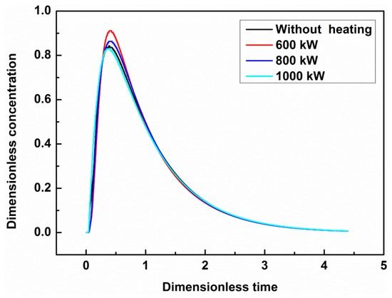
Figure 12.
RTD curves in the tundish with different heating powers.
Table 2.
Flow characteristics in the new tundish with different heating powers.
3.3.4. Turbulence Intensity
Figure 13 presents the turbulence intensities of the vertical section at plane 1 in the tundish with different heating powers. Figure 14 shows the turbulence intensities of the cross-section at plane 2 in the tundish with different heating powers. It can be seen from Figure 13 that the turbulence intensity is almost kept unchanged and distributes evenly with the increasing heating power. This indicates that the new tundish with the optimal channel radius is favorable to realize the steady casting with low superheat. Figure 14 illustrates that the turbulence intensities in the channels become higher with the increasing heating power [12]. It indicates that the increment of the heating power is beneficial for the collision growth of the inclusions in the channels and improvement of the inclusions removal in the present work.
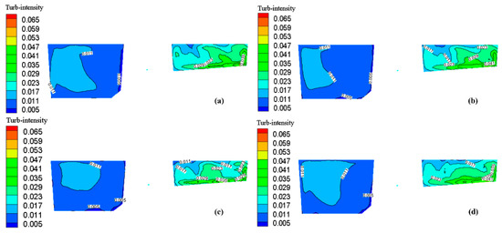
Figure 13.
Turbulence intensities of a vertical section at plane 1 in the tundish with different heating powers. (a) Without induction heating. (b) 600 kW. (c) 800 kW. (d) 1000 kW.
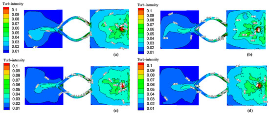
Figure 14.
Turbulence intensities of a cross-section at plane 2 in the tundish with different heating powers. (a) Without induction heating. (b) 600 kW. (c) 800 kW. (d) 1000 kW.
3.3.5. Inclusion Removal Rate
Figure 15 displays the removal rates of inclusions with different heating powers. As indicated in Figure 15a, for each size, the removal rate is much lower without induction heating, and with the increase of heating power, the removal rate becomes higher, which confirms the conclusion obtained from Figure 14. It can also be seen in Figure 15b that the total removal rate also becomes higher with the increasing heating power, and the total removal rate increases larger than the single removal rates. The reason is that compared to the inclusions of each size, the inclusions of all sizes are more likely to grow up in collisions.
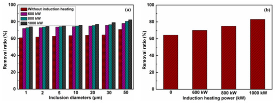
Figure 15.
Removal rates of inclusions with different heating powers. (a) Each size. (b) All sizes.
4. Conclusions
A 3D transient mathematical model is established to investigate the effects of both the channel radius and heating power on the flow field, temperature field, and removal rate of inclusions. The conclusions are:
- The channel radius of 2 m is poor on flow control because of the obvious chaotic flow and slag/steel interface fluctuation in the discharging chamber. The channel radius of 3 m shows better flow characteristics than those with the channel radii of 4 m and 2 m.
- With different channel radii, the temperature distributions are uniform in the discharging chambers. The radius of 3 m is the best one for heating efficiency.
- For each size, the radii of 3 m and 2 m show good efficiency on inclusion removal, which is poor when the radius is 4 m. There is small difference in inclusion removal between the radii of 3 m and 2 m. For all the sizes, the same phenomenon can also be seen.
- Under the optimal channel radius of 3 m, compared with 600-kW heating power, the tundish with 800-kW heating power is more efficient regarding controlling the flow. When the heating power is increased to 1000 kW, the flow field becomes chaotic in the discharging chamber.
- The liquid steel temperature of the discharging chamber rises with the increasing heating power, and the temperature fields are uniform. With 1000-kW heating power, the temperature field in the discharging chamber becomes nonuniform, and the temperature difference is large.
- As the heating power increases, the inclusion removal efficiency also increases. The total inclusion removal efficiency is also increased, and the total removal rate increases more than the single removal rates.
Author Contributions
Data curation, F.X., Z.L.; Funding acquisition, S.Z.; Investigation, F.X., S.Z.; Project administration, S.Z.; Resources, M.Z.; Writing–original draft, F.X.; Writing–review & editing, S.Z., M.Z.
Funding
This research was supported by the National Key R&D Program of China (No. 2017YFC0805100), the National Natural Science Foundation of China (No. 51774077, No. 51474059, No. U1560208) and the Fundamental Research Funds for the Central Universities of China (N172504030).
Acknowledgments
The authors are grateful to the National Key R&D Program of China, the National Natural Science Foundation of China and the Fundamental Research Funds for the Central Universities of China, which enabled the research to be carried out successfully.
Conflicts of Interest
The authors declare no conflict of interest.
References
- Zhao, B.; Thomas, B.G.; Vanka, S.P.; O’Malley, R.J. Transient fluid flow and superheat transport in continuous casting of steel slabs. Metall. Mater. Trans. B 2005, 36, 801–823. [Google Scholar] [CrossRef]
- Huang, X.; Thomas, B.G.; Najjar, F.M. Modeling superheat removal during continuous casting of steel slabs. Metall. Mater. Trans. B 1992, 23, 339–356. [Google Scholar] [CrossRef]
- Chakraborty, S.; Sahai, Y. Effect of slag cover on heat loss and liquid steel flow in ladles before and during teeming to a continuous casting tundish. Metall. Mater. Trans. B 1992, 23, 135–151. [Google Scholar] [CrossRef]
- Yang, S.F.; Zhang, L.F.; Li, J.S.; Peaslee, K. Structure optimization of horizontal continuous casting tundishes using mathematical modeling and water modeling. ISIJ Int. 2009, 49, 1551–1560. [Google Scholar] [CrossRef][Green Version]
- Zhou, J.A.; Xie, J.B.; Wang, B.; Lei, H.; Zhang, H.; Ni, H.W. Heat transfer of steel in a slab tundish with vacuum chamber. ISIJ Int. 2017, 57, 1037–1044. [Google Scholar] [CrossRef]
- Yoshii, Y.; Habu, Y.; Yamanaka, H. Method of Heating a Molten Steel in a Tundish for a Continuous Casting Apparatus. U.S. Patent No. 4,582,531, 15 April 1986. [Google Scholar]
- Umbrashko, A.; Baake, E.; Nacke, B.; Jakovics, A. Modeling of the turbulent flow in induction furnaces. Metall. Mater. Trans. B 2006, 37, 831–838. [Google Scholar] [CrossRef]
- Wang, Q.; Li, B.K.; Tsukihashi, F. Modeling of a thermo-electromagneto-hydrodynamic problem in continuous casting tundish with channel type induction heating. ISIJ Int. 2014, 54, 311–320. [Google Scholar] [CrossRef]
- Yue, Q.; Zhang, C.B.; Pei, X.H. Magnetohydrodynamic flows and heat transfer in a twin-channel induction heating tundish. Ironmak. Steelmak. 2017, 44, 227–236. [Google Scholar] [CrossRef]
- Yang, B.; Lei, H.; Bi, Q.; Jiang, J.; Zhang, H.W.; Zhao, Y.; Zhou, J.A. Electromagnetic conditions in a tundish with channel type induction heating. Steel Res. Int. 2018, 89, 1800145. [Google Scholar] [CrossRef]
- Yang, B.; Lei, H.; Bi, Q.; Jiang, J.; Zhang, H.W.; Zhao, Y.; Zhou, J.A. Fluid flow and heat transfer in a tundish with channel type induction heating. Steel Res. Int. 2018, 89, 1800173. [Google Scholar] [CrossRef]
- Wang, Q.; Li, B.K.; Tsukihashi, F. Behavior of non-metallic inclusions in a continuous casting tundish with channel type induction heating. ISIJ Int. 2014, 54, 2796–2805. [Google Scholar] [CrossRef]
- Xing, F.; Zheng, S.G.; Zhu, M.Y. Motion and removal of inclusions in new induction heating tundish. Steel Res. Int. 2018, 89, 1700542. [Google Scholar] [CrossRef]
- Li, B.K. Metallurgical Application of Advanced Fluid Dynamics; Metallurgical Industry Press: Beijing, China, 2003. [Google Scholar]
- Vives, C.; Ricou, R. Proceedings of the 6th International Iron and Steel Congress; Iron and Steel Institute of Japan: Tokyo, Japan, 1990. [Google Scholar]
- Kenji, U.; Yasuji, T.; Kazuhisa, M. Proceedings of the 5th International Symposium on Electromagnetic Processing of Materials; Iron and Steel Institute of Japan: Tokyo, Japan, 2006. [Google Scholar]
- Pardeshi, R.; Basak, S.; Singh, A.K.; Basu, B.; Mahashabde, V.; Roy, S.K.; Kumar, S. Mathematical modeling of the tundish of a single-strand slab caster. ISIJ Int. 2004, 44, 1534–1540. [Google Scholar] [CrossRef]
- Mazumdar, D.; Guthrie, R.I.L. The physical and mathematical modeling of continuous casting tundish systems. ISIJ Int. 1999, 39, 524–547. [Google Scholar] [CrossRef]
- Li, B.K.; Okane, T.; Umeda, T. Modeling of molten metal flow in a continuous casting process considering the effects of argon gas injection and static magnetic-field application. Metall. Mater. Trans. B 2000, 31, 1491–1503. [Google Scholar] [CrossRef]
- Zhong, L.C.; Li, B.K.; Zhu, Y.X.; Wang, R.G.; Wang, W.Z.; Zhang, X.J. Fluid flow in a four-strand bloom continuous casting tundish with different flow modifiers. ISIJ Int. 2007, 47, 88–94. [Google Scholar] [CrossRef]
- Chen, D.F.; Xie, X.; Long, M.J.; Zhang, M.; Zhang, L.L.; Liao, Q. Hydraulics and mathematics simulation on the weir and gas curtain in tundish of ultrathick slab continuous casting. Metall. Mater. Trans. B 2014, 45, 392–398. [Google Scholar] [CrossRef]
- Kumar, A.; Mazumdar, D.; Koria, S.C. Modeling of fluid flow and residence time distribution in a four-strand tundish for enhancing inclusion removal. ISIJ Int. 2008, 48, 38–47. [Google Scholar] [CrossRef]
- Cho, M.J.; Kim, I.C. Simple tundish mixing model of continuous casting during a grade transition. ISIJ Int. 2006, 46, 1416–1420. [Google Scholar] [CrossRef]
- Sahai, Y.; Emi, T. Melt flow characterization in continuous casting tundishes. ISIJ Int. 1996, 36, 667–672. [Google Scholar] [CrossRef]
- Sahai, Y.; Ahuja, R. Fluid-flow and mixing of melt in steelmaking tundishes. Ironmak. Steelmak. 1986, 13, 241–247. [Google Scholar]
- Zheng, S.G.; Zhu, M.Y. Optimisation of baffles in six strand round bloom continuous casting tundish: A physical modelling study. Ironmak. Steelmak. 2006, 33, 398–406. [Google Scholar] [CrossRef]
- Yu, H.Q.; Zhu, M.Y. Numerical simulation of the effects of electromagnetic brake and argon gas injection on the three-dimensional multiphase flow and heat transfer in slab continuous casting mold. ISIJ Int. 2008, 48, 584–591. [Google Scholar] [CrossRef]
- Fujisaki, K.; Satoh, S.; Yamada, T. Consideration of heat transfer and solidification in 3-D MHD calculation. IEEE Trans. Magn. 2000, 36, 1300–1304. [Google Scholar]
- Ramos, J.P.; Barreto, J.J.; Lopez-Ramirez, S.; Morales, R.D. Melt flow optimisation using turbulence inhibitors in large volume tundishes. Ironmak. Steelmak. 2001, 28, 101–109. [Google Scholar] [CrossRef]
- Ghojel, J.I.; Ibrahim, R.N. Computer simulation of the thermal regime of double-loop channel induction furnaces. J. Mater. Process. Tech. 2004, 155, 386–391. [Google Scholar] [CrossRef]
- Zhang, L.F.; Taniguchi, S.; Cai, K.K. Fluid flow and inclusion removal in continuous casting tundish. Metall. Mater. Trans. B 2000, 31, 253–266. [Google Scholar] [CrossRef]
- ANSYS Fluent 14.0—User’s Guide; ANSYS Inc.: Canonsburg, PA, USA, 2011.
© 2019 by the authors. Licensee MDPI, Basel, Switzerland. This article is an open access article distributed under the terms and conditions of the Creative Commons Attribution (CC BY) license (http://creativecommons.org/licenses/by/4.0/).