Article

Automated Continuous Production Line of Parts Made of Metallic Foams

1
Department of Mechanical Engineering, Centre for Mechanical Technology and Automation (TEMA), University of Aveiro, Campus Universitário de Santiago, 3810-193 Aveiro, Portugal
2
Faculty of Mechanical Engineering, University of Maribor, Smetanova ul. 17, SI-2000 Maribor, Slovenia
3
M.J.Amaral-Equipamentos Industriais Lda, Apartado 14, Bouça da Aguincheira-São Pedro de Castelões, 3730-038 Vale de Cambra, Portugal
*
Author to whom correspondence should be addressed.
Metals 2019, 9(5), 531; https://doi.org/10.3390/met9050531
Submission received: 20 April 2019 / Revised: 28 April 2019 / Accepted: 6 May 2019 / Published: 8 May 2019
(This article belongs to the Special Issue Cellular Metals: Fabrication, Properties and Applications)

Abstract

:
The paper presents an automated continuous production line (7 m × 1.5 m × 1 m) of high-quality metallic foams using a powder metallurgical method. This continuous production line was used to obtain metal foam parts and/or components by heating the foamable precursor material at melting temperatures close to the temperature of the metallic matrix and cooling the formed liquid metallic foam (in liquid state), which then results in a solid closed-cell metallic foam. This automated continuous production line is composed of a continuous foaming furnace, a cooling sector and a robotic system. This installation has enabled a technological breakthrough with many improvements solving some technical problems and eliminating the risks and dangers related to the safety of workers due to the high temperatures involved in this process. The whole process becomes automatic without any need for human intervention.

1. Introduction

Metallic foams are one of the most interesting lightweight materials that have a high potential to be used in large-scale in various areas of engineering. They are multifunctional, lightweight, recyclable and non-flammable with reduced environmental impact. The fact that they may be formed by open-cells and/or closed-cells, makes it possible for them to be widely used in the near future [1]. The open-cell metallic foams are mainly used as functional materials for chemical and biomedical applications (e.g., treatment of water, heat exchangers) [2]. The closed-cell foams are used as structural materials for commercial, industrial and military applications (e.g., energy absorbing structures, ballistic protection) [1,3,4,5]. The latter exhibit an excellent structural efficiency and excellent capacity to absorb (impact and sound) energy, together with noise and vibration damping in structures such as houses, cars, trains and other devices and equipment [6]. These special advantages are a combination of properties derived from their porous cellular structures along with the properties of the metal they are made of. These foams are considered as one of the future materials that must be lightweight, durable, ecofriendly and economical. When compared to the other foams made of polymer and ceramic, these foams have more potential. Polymer foams [7] are flexible, but cannot support high temperatures, while metallic ones are extremely tough and can plastically deform and possess a high capacity of energy absorption. Also, metallic foams are easily recyclable unlike some polymeric foams, which cannot be recycled or, if they are, it is quite expensive. Moreover, polymeric foams increase fire hazards, releasing smoke and toxic gases, which does not happen with the non-flammable metallic foams. Ceramic foams [8] are relatively stiff, endure high thermal shocks and are more stable in harsh environments compared with metallic and polymer foams. However, ceramic foams have a brittle behavior that limits their uses, while metallic foams have a ductile behavior that is more appropriate for engineering purposes. Despite the advantages of metallic foams, they have not been used in a large scale yet. The main reason is the fact that the current manufacturing processes to prepare the closed-cell foams do not allow a meticulous control of the cellular structures in terms of their pores’ shape and size. The control of cellular structures of these foams will make it possible to predict the mechanical, thermal and electrical behavior.
Two main strategies have been adopted to achieve cellular metals with regular structures. The first strategy consists of improving the most viable existing manufacturing processes, as the case of the powder metallurgy that allows the preparation of the ductile metallic foams to be used as structural materials. Powder metallurgy method consists of heating a foamable precursor material to a temperature close to the melting temperature of the metallic matrix in which this foamable precursor material is prepared by the hot compaction of a mixture of the metal and blowing agent powders [9]. The improvement was achieved by using pre-treated blowing agent powder (e.g., titanium hydride) instead of untreated powder, ensuring that the initial decomposition temperature is close to the melting temperature of the metallic matrix [10]. The second strategy is to develop new classes of the cellular metals with closed pores using methods that allow the control of the size and shape of their pores. Advanced pore morphology (APM) metallic foam elements [11], syntactic foams [12] and hybrid foams [13] are some of these examples. The APM metallic foam elements are simple spheres of metal closed-cell foams, which are obtained by the powder metallurgy method using the smallest pieces of the precursor material (e.g., 1–2 mm in size) [11]. The small sample sizes ensure that surface tension forces during the melting process are relatively large compared to the hydrostatic pressure, forming near spherical shapes with an easily reproducible unit cell [14]. Syntactic foams are prepared by infiltrating a metal melt into the interstice’s spaces of a packed hollow spheres made of metal or ceramic or porous particles [15,16]. Hybrid foams are prepared by impregnating an open-cell metal foam with a polymer [17]. Despite these developments, the closed-cell metallic foams prepared by the traditional powder metallurgy method have several advantages in comparison with other new cellular metals. For example, the syntactic foams have high density (>2 g/cm3) when compared to the typical closed-cell metal foams (<1 g/cm3) that limits their application, especially for lightweight constructions [6]. Also, in the case of hybrid foams the use of polymers increases the risk of fire hazards. Furthermore, the powder metallurgy method allows to fabricate parts with complex geometries, to fill the hollow structures with a formed liquid metal foam during its formation [18] and to easily incorporate metallic inserts (e.g., screws) [19] into the metal foam during its formation, promoting a metallic bonding. For example, aluminum alloy closed-cell foams have been extensively tested as core [20] and filler materials [21,22] of sandwich structures and thin-walled tubes, mainly to be used as energy absorbing structures for vehicles in which the joining between the solid thin-walled structure and the closed-cell aluminum alloy foam is made during the foam formation. However, since the metallic foam component is prepared using a batch furnace, the quality of the components depends on several factors including manufacturing parameters (e.g., temperature and time) and the experience of the workers. In order to have a strict control over the process, without the need of human intervention in dangerous tasks, an automated continuous production line was developed to obtain parts and/or components of metallic foams. This article presents this production line, illustrating several case-studies as well as the potentiality of this newly developed installation.

2. Materials and Methods

Two foamable precursor materials with 160 × 20 mm (Figure 1a) and 20 mm × 5 mm (Figure 1b) in cross-section, made of AlSi7 alloy with 0.5 wt. % of titanium hydride were prepared by a combination of cold isostatic pressing and hot extrusion as described in [23]. Table 1 presents characteristics of the used powders. The powder mixture of aluminum alloy and titanium hydride were first compacted to cylindrical slugs with 70–80% of theoretical density by cold isostatic pressing (CIP). After this, the cylindrical slug was pre-heated to 360 °C and extruded to rectangular bars of 160 × 20 mm and 20 mm × 5 mm in cross-section through a horizontal 25 MN direct extrusion machine. Closed molds made of S235JR carbon steel (0.17% C, 1.40% Mn, 0.045% P, 0.045% S, 0.009% N) were made using steel plates and thin-walled tubes. Square (outer width: 25 mm; wall thickness: 2 mm) and cylindrical (outer diameter: 30 mm; wall thickness: 1.5 mm) thin-walled tubes made of AA 6060 T66 having an outer and inner diameter of 30 mm and 26 mm, respectively, were cut to the required length (e.g., 150 mm). Carbon steel bars (diameter: 4 mm) made of S235JRG2C (0.20% C, 1.40% Mn, 0.045% P, 0.045% S) were used as reinforcements to prepare the in-situ reinforced foams.
The compressive and three-point bending properties presented in this work were measured using a 50 kN servo-hydraulic dynamic INSTRON 8801 testing machine (Instron, Norwood, MA, USA) under quasi-static loading conditions (crosshead loading rate: 0.1 mm/s).

3. Results

The development of this automated continuous production line was based on the thorough knowledge acquired in the fabrication of metallic foams using laboratory batch furnaces [9,23]. In the traditional process, a foamable precursor material is placed into the cavity of a closed mold. The worker places the mold containing the precursor into a pre-heated furnace at high temperatures. This is a dangerous task for the worker due to exposure to extremely high temperatures (700–800 °C for the case of aluminum alloys). The total weight of the mold with the foamable precursor material should also be appropriate for the easy handling by the worker.
After that, the heating of the foamable precursor material leads to a formation of the liquid metallic foam due to the thermal decomposition of the blowing agent and the melting of the metal. The precursor expands, filling the cavity of the mold. During this step, the worker should supervise the exterior of the mold to follow the filling process of the mold. When the first melt leaves the mold, the worker must quickly yet carefully remove the mold containing the formed liquid metallic foam. In addition to this, the formed liquid foam must be solidified immediately to prevent the collapse mechanisms (drainage and coalescence) and must be done in a very steady manner to avoid any turbulent movements that could damage the foam [24]. This is another dangerous task in which the worker is, once again, exposed to extremely high temperatures. To perform the dangerous tasks, the workers should use personnel protective equipment, such as heat protection clothing, gloves and safety glasses. In the traditional procedure, the cooling is not controlled since it is the worker who cools the surrounding of the mold with a hose of compressed air until room temperature is obtained. Results show that formation of defects and structural imperfections within solid foams are created due to the fact, that the solidification is not uniform [25]. All of these aspects could increase the number of rejected metallic foam pieces. Automated continuous production line was developed to eliminate the dangerous tasks performed by the workers, to ensure that the quality of the foam is not compromised by the experience of the worker and to guarantee a controlled solidification. The main components of the continues production line are the continuous furnace, cooling sector and robotic system that will be described below.

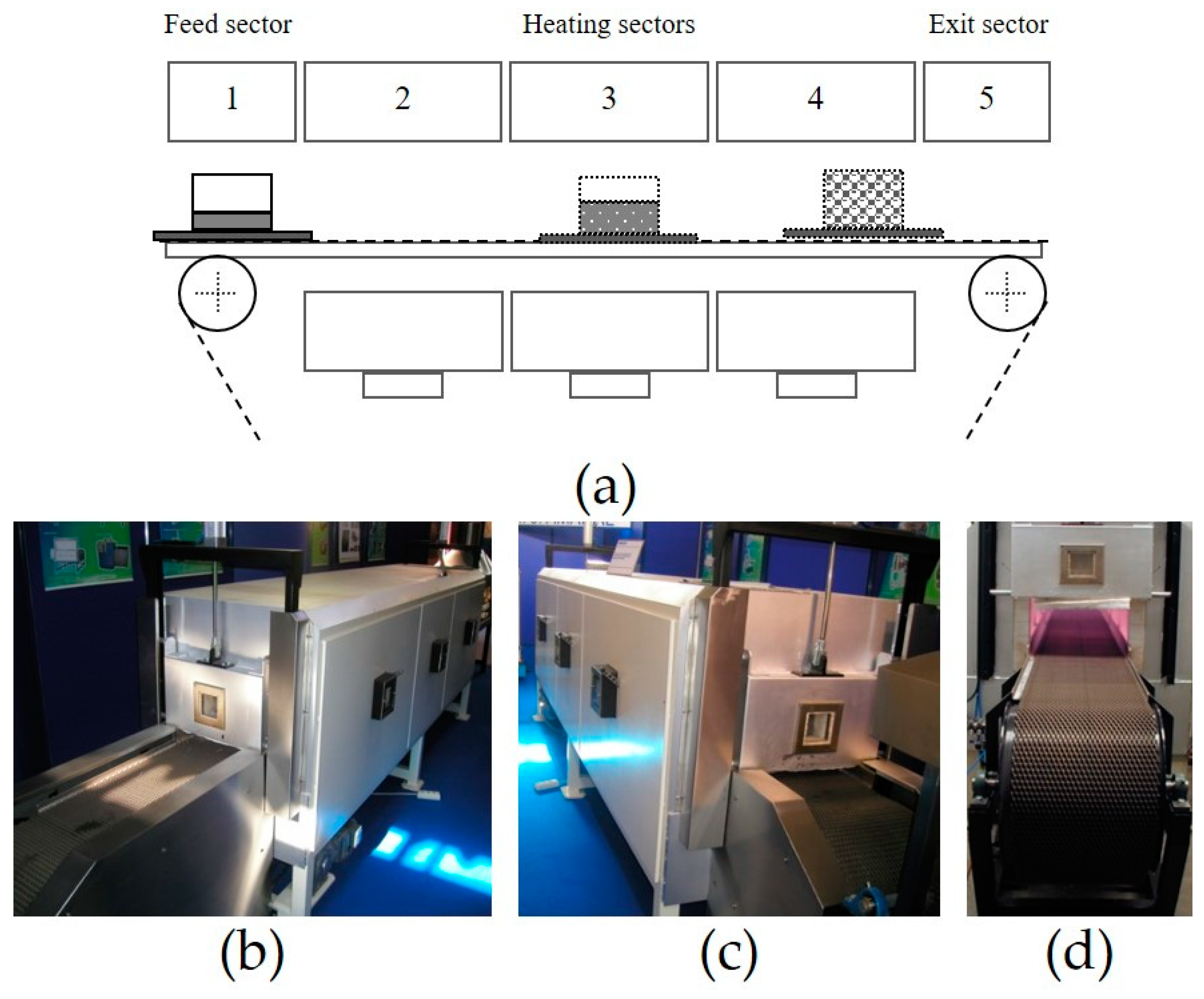
3.1. Continuous Foaming Furnace

Figure 2 shows a scheme (Figure 2a) and photos (Figure 2b–d) of the continuous foaming furnace developed to fabricate 3D components of metallic foams. This continuous furnace has five zones, which are the feed zone of the foamable precursor material into the molds (open or closed) or into the thin-walled structures, followed by the three heating zones and the exit zone. The loading and movement of the foamable precursor material within the furnace is achieved by means of a conveyor belt, as shown in Figure 2d. The length of the feed zone is approximately 0.7 m (Figure 2b), while the length of the exit zone is approximately 0.3 m (Figure 2c).
The furnace has three heating zones respective to the three foaming stages until the maximum expansion value is reached [26]. The first foaming stage accounts for temperatures below the solidus temperature of the metallic matrix, where the expansion is very small. In the second foaming stage, a rapid increase of expansion is observed due to the metal being in liquid state and due to the releasing of the gas into the metal from by the thermal decomposition of the blowing agent, simultaneously. The third foaming stage also represent a rapid increase in expansion as the temperature increases until the maximum expansion is reached. After that, gas is no longer released, and the formed liquid foam starts to collapse due to the coalescence and drainage mechanisms. Thus, the formed liquid metallic foam should be removed from the furnace once it is close to the maximum expansion to avoid its collapse. The three heating zones are of the same dimensions (size: 0.3 m in height and 0.4 m in width) and could be controlled individually according to the thermal foaming cycle.
All of the heating zones could be operated from room temperature up to 1273 K. This furnace is heated by means of electrical resistances, which were installed at the top of the furnace and under the conveyor belt. The conveyor belt is made of stainless-steel chains to support the weight of the foamable precursor material and molds or hollow structures, as well as the thermal fatigue during the thermal foaming cycle.
Two panel doors were installed in the furnace to decrease the temperature variation throughout the heating zones, as well as to reduce the turbulence airflows effect. One of them is located at the entrance of the first heating zone (Figure 2b) and the other is located at the end of the third heating zone of the furnace (Figure 2c). Both panel doors have windows for observation of the furnace’s interior. Each heating zone (Figure 2b,c) has also got a window located on the sidewall of the front furnace for visualizing and controlling the foaming process. The movement of the foamable precursor material within the furnace is associated with the movement of the conveyor belt created by a set of engines and transmission systems. The maximum linear speed of the conveyor belt is approx. 0.5 m/s. The temperature of the three heating zones and speed rate of the conveyor belt should be adjusted according to the characteristics of the foamable precursor material and the geometry and dimensions of the component to be fabricated. Figure 3 shows two examples of rejected foam parts (Figure 3a,b) and the block foam prepared with adjusted parameters (Figure 3c). The use of a high speed of the conveyor belt and/or low temperatures of the heating zones will not allow enough time for the precursor material to expand and filling the cavity of the mold, as shown in Figure 3a. On the other hand, a very low speed rate of the conveyor belt promotes the collapse of the foam since the formed liquid metallic foam remains at high temperatures for a long time, leading to a high loss of the liquid metal, as can be seen in Figure 3b. For each foam part, the parameters of the furnace should be adjusted to obtain a high-quality foam as shown in Figure 3c.

3.2. Cooling Sector and Robotic System

A cooling sector was designed and built to control the solidification of the liquid metallic foam, decreasing the number of rejected foam parts. In fact, uncontrolled solidification of the liquid metallic foam causes defects and structural imperfections, decreasing the mechanical properties of the resulting solid metal foams. Figure 4 shows rejected parts and nearly perfect foam parts, which were prepared with uncontrolled (Figure 4a) and controlled (Figure 4b) cooling, respectively.
This cooling sector was installed immediately after the continuous foaming furnace. The robotic system was also built and installed in the cooling sector to extract the mold or the hollow structures filled with the liquid metallic foam from the furnace at high temperatures to the cooling sector, making it an automatic operation without any human intervention. Figure 5 shows a 3D model of the cooling sector (Figure 5a) composed by the robotic system (Figure 5b), the cooling systems and the conveyor belt (Figure 5c) designed by SolidWorks software. Figure 6 shows real photos of the cooling sector and an overview of the final automated continuous production line.
The cooling sector is a metallic structure equipped with a high-pressure turbine connected to two manifolds drilled and mounted on both sides of a conveyor belt. The angle of the manifolds drilled varies according to the dimensions of the required component. A robotic system was developed to extract the mold containing the formed liquid metallic foam from the furnace at a high temperature to the cooling sector, which makes it possible to operate it without any human intervention required. This robotic system is installed in the cooling sector. The mechanical arm is built from stainless steel AISI 304 and is mounted at the vertical rail made of aluminum and a horizontal rail made of the same material, as shown in Figure 6. The vertical drive is controlled by a pneumatic cylinder, while the horizontal one is controlled by a motor reducer with the possibility of adjusting the speed rates and positions. The movement of this robotic system is associated with the command of the opening and closing of the furnace door at the end of the third heating zone. The mechanical arm system receives a trigger signal, starts to move towards the furnace door, while the furnace door also opens. This signal is triggered when the mold touches the suspended metal chain in the third heating zone. Briefly, the sequence steps during this operation are:
  • The signal is emitted, triggering the start of two immediate mechanisms: the opening of the furnace door and the course of the mechanical arm into the furnace;
  • The mechanical robotic system arm dovetails in the tray containing the mold with the formed liquid foam;
  • The mechanical robotic system arm extracts the tray containing the mold with the formed liquid foam (third heating zone) from the furnace, and puts it into the cooling sector;
  • The mechanical system arm puts the tray on the second conveyor belt and the furnace door is closed, simultaneously.
This last operation is associated to the velocity of the conveyor belt of the cooling sector, which is different from the first conveyor belt of the continuous furnace. Two conveyor belts were installed to avoid any interference between the foaming process and the solidification of the formed liquid foam to solid foam. The first conveyor belt moves the precursor material from the loading sector through the continuous furnace to the exit sector, where the expansion of the precursor occurs. The second conveyor belt is placed in the cooling sector, where the foam is solidified. Both carrier conveyor belts are made of stainless-steel chains. The steel chains were designed to support temperatures up to 1000 °C in continuous operation, to assure a good thermal fatigue resistance, a good corrosion resistance, good dimensional stability and a good resistance to weld to the workpiece surface. The movement of the precursor material (with or without the mold) is associated to the movement of the conveyor belt created by the engine/motors and the drums. This is equipped by drive motors that ensure a continuous motion through the furnace and the rate variations according to the materials to be expanded. The control of the velocity of the conveyor belt and temperatures of each heating zones are programmed according to the required thermal cycle of foaming.

3.3. Operation Mode

The operation mode of the automated continuous foaming production line is as follows:
  • The loading of the mold (open or closed) or the hollow structures containing the foamable precursor material is placed into a stainless-steel tray in the feed sector of the continuous foaming furnace on the conveyor belt at the room temperature.
  • The first furnace door is opened and the tray with the mold and foamable precursor material enters the furnace.
  • The first furnace door is closed immediately after the tray enters the furnace.
  • The tray containing the mold and the precursor material moves through the conveyor belt by a controlled motion through the three heating zones. The foamable precursor material expands, filling the mold completely.
  • The mold reaches the three-heating zones and touches the suspended metallic chains. This physical contact activates a signal to start the operation of extracting the mold with the formed liquid metallic foam by the robotic system, which is associated with the command of opening/closing the second furnace door. The mechanical arm system activates the movement towards the furnace and the furnace door at the end of the continuous furnace starts to open.
  • The mechanical system arm enters in the third heating sector of the furnace and dovetails in the tray, which was developed for this purpose.
  • The mechanical arm system begins the transportation of the mold with the liquid metallic foam and places it on the conveyor belt of the continuous foaming furnace that is programmed to ensure the uniform solidification of the formed foam up to the room temperature.
  • The worker can open the mold and extract the resulting component made of solid metallic foam.
The command and control parameters of the entire installation are performed through one electric console. For example, it controls the thermal foaming cycle associated to each heating zone, the velocities of the conveyor belts, as well as the movement of the doors.

3.4. Case-Studies

Simple and complex parts made of aluminum alloy foams were fabricated using this automated continuous production line. The closed mold is built according to the dimensions and geometry of the foam part to be fabricated. Figure 7 illustrates an example to fabricate a complex foam part, showing the 3D model designed in SolidWorks software (Figure 7a), the closed mold made of stainless steel constructed for this purpose (Figure 7b) and finally, the components made of aluminum alloy (Figure 7c).
The molds could be fabricated using screw system or clamping system, as illustrated in Figure 8a,b respectively. The use of molds with clamping system makes it much easier to extract the resulting solid foam components compared to those with screw system, which require a special tool, reducing the global production time. Figure 9 shows examples of real molds with screw system (Figure 9a) and with clamping system (Figure 9b), which were constructed to prepare aluminum alloy foam parts.
Figure 10 shows simple and complex foam parts made of aluminum alloys fabricated using this automated continuous production line with stainless steel molds constructed for each component. The foamable precursor material is selected according to the dimensions and geometry of the respective component. For example, the foam blocks and the complex foam parts were prepared using the foamable precursor material with 160 mm × 20 mm in cross-section (Figure 1a). Simple thin foam panels and sandwich foam panels were prepared using the foamable precursor material with 20 mm × 5 mm in cross-section (Figure 1b). The rectangular block of the foamable precursor material (160 mm × 20 mm in cross-section) is usually cut according to the characteristics of the foam component to be fabricated (volume, geometry and dimensions). However, foam parts could be fabricated using various small precursor pieces (Figure 11a) instead of a single precursor [27], as illustrated in Figure 11.
This manufacturing process has several advantages when compared to other existing processes to produce metallic foams. It enables the production of parts and components of complex geometry of good quality in a simple, effective and practical way, as illustrated in Figure 7 and Figure 10b. Another advantage is that it joins the metal foams with other materials during its foam formation, promoting a metallic bonding. This facilitates and simplifies its application, since it eliminates the expensive joining step, leading to highly competitive products. Moreover, the application of the common joining techniques [28,29,30], such as welding and brazing, damages the cellular structures of the foams. The aluminium alloy foams are usually used as a core or a filler of sandwich panels and thin-walled structures, respectively. Results have shown that it is possible to fabricate in-situ foam filled tubes [18,20] (Figure 12a) and in-situ sandwich foam panels [21] (Figure 12b) using aluminium alloy tubes or aluminium alloy sheets by applying this manufacturing process. The manufacturing conditions could be adjusted to ensure the structural integrity of these sheets or tubes when exposed to high foaming temperatures that are close to the melting temperature of the alloy. Results have also demonstrated that the thermal treatment that is submitted to these tubes or sheets at high temperatures during the foam formation is beneficial to obtain a predictable and stable mechanical behavior of the resulting in-situ foam structures. The ductility of these structures increases, leading to an efficient crashworthiness without formation of cracks and abrupt failure when subjected to compressive and bending loads. Results also show that the global weight of the resulting in-situ foam structures can be controlled by reducing the wall thickness of the tubes or sheets [18]. Moreover, the metallic inserts could be incorporated into the foams [31], resulting in in-situ reinforced foams, as shown in Figure 12c. This could be an advantage for the industry. For example, fasteners or other standard parts used in vehicles, like screws, bolts and pin rivets could be incorporated, minimizing the discontinuity, slip and fracture under loading utilized in the processes such as screwing.
The metallic foams prepared by powder metallurgy method have a more ductile behavior when compared to the direct foaming methods [32,33]. In addition to this, the broad spectrum of foam parts with a free design can be easily fabricated with a good surface finish (Figure 10 and Figure 12c) as an outer surface dense (integral) skin around each component is created during its production. Results have demonstrated that the powder metallurgy is a near-net shape manufacturing technology that produces foam components close to the finished size and shape, minimizing the number of secondary finishing processes. Results have shown that this technology allows a reduction in the number of processing steps (no joining step), a significant reduction in the amount of waste material and an ability to easily produce complex and advanced geometries. Results have indicated that AlSi7 foam parts or components could be fabricated at 700 °C. Table 2 and Table 3 give an overview of the main properties of some parts made of aluminum alloy foams, in which some of them are presented in Figure 10, Figure 11 and Figure 12, such as the cubic and cylindrical integral-skin foams, in-situ foam filled tubes made of aluminum alloys and in-situ reinforced carbon steel reinforced foams. The compressive and bending strengths of these foams increase with the foam density.
The compressive strength of the foam components is higher than the bending strength. In fact, the closed-cell aluminum foams are used as crash energy absorbers.
Results have demonstrated that the larger the foam blocks, the higher the cellular architecture variation due to a non-uniform foam growth during the heating of the single precursor material [34,35]. For smaller foam blocks [34], a more regular distribution of the pores through the foam is obtained.

4. Conclusions

The automated continuous production line composed of a continuous furnace, a cooling sector and a robotic system is approximately 7 m long, 1.5 m high and 1 m wide. This foaming production line allows the production of larger quantities of foam materials when compared to those fabricated by the batch furnace. The new production line has several advantages in comparison to the conventional procedures as follows:
  • The transition from a manual operation (piece by piece production) to an automated and continuous operation;
  • The quality of the formed foam parts no longer depends on the experience and training of the worker since the process is automated;
  • The safety of workers is ensured and no personnel protective equipment (e.g., heat protection clothing, gloves and safety glasses) is necessary. The workers only carry out tasks at the room temperature;
  • No limitation in terms of weight, due to the support of the mechanical arm system;
  • The automatic and controlled extraction operation of formed foams from the heating zone to the cooling sector prevents the collapse of the foams and reduces the number of rejected parts;
  • The controlled cooling ensures uniform solidification of the foam in all directions and avoids the appearance of defects in formed parts, especially in larger pieces, avoiding inferior mechanical properties;
  • The volume of production of foam parts per unit time increases.

Author Contributions

Conceptualization, I.D. and M.J.V.; methodology, I.D. and M.J.V.; validation, I.D., M.J.V. and M.V.; formal analysis, I.D. and M.V.; investigation, I.D. and M.V.; data curation, I.D. and M.V.; writing—original draft preparation, I.D. and M.V.; writing—review and editing, I.D. and M.V.; visualization, I.D.; supervision, I.D.

Acknowledgments

Supports given by M. J. Amaral-Equipamentos Industriais Lda (Vale de Cambra), the Portuguese Science Foundation (FCT), UID/EMS/00481/2019-FCT and CENTRO-01–0145-FEDER-022083 (Centro 2020 program-Portugal 2020).

Conflicts of Interest

The authors declare no conflict of interest.

References

  1. García-Moreno, F. Commercial Applications of Metal Foams: Their Properties and Production. Materials 2016, 9, 85. [Google Scholar] [CrossRef]
  2. Kim, S.; Lee, C.-W. A Review on Manufacturing and Application of Open-cell Metal Foam. Procedia Mater. Sci. 2014, 4, 305–309. [Google Scholar] [CrossRef] [Green Version]
  3. Garcia-Avila, M.; Portanova, M.; Rabiei, A. Ballistic performance of composite metal foams. Compos. Struct. 2015, 125, 202–211. [Google Scholar] [CrossRef]
  4. Vesenjak, M.; Borovinšek, M.; Ren, Z.; Irie, S.; Itoh, S. Behavior of Metallic Foam under Shock Wave Loading. Metals 2012, 2, 258–264. [Google Scholar] [CrossRef]
  5. Shim, C.; Yun, N.; Robin Yu, R.; Byun, D. Mitigation of Blast Effects on Protective Structures by Aluminum Foam Panels. Metals 2012, 2, 170–177. [Google Scholar] [CrossRef] [Green Version]
  6. Duarte, I.; Peixinho, N.; Andrade-Campos, A.; Valente, R. Special Issue on Cellular Materials. Sci. Technol. Mater. 2018, 30, 1–3. [Google Scholar] [CrossRef]
  7. Obi, B. Polymeric Foams Structure-Property-Performance: A Design Guide, 1st ed.; Imprint William Andrew Elsevier Inc.: Oxford, UK, 2017. [Google Scholar]
  8. Scheffler, M.; Colombo, P. Cellular Ceramics, Structure, Manufacturing, Properties and Applications; WILEY-VCH Verlag GmbH: Weinheim, Germany, 2005. [Google Scholar]
  9. Duarte, I.; Banhart, J. A study of aluminium foam formation—Kinetics and microstructure. Acta Mater. 2000, 48, 2349–2362. [Google Scholar] [CrossRef]
  10. Matijasevic-Lux, B.; Banhart, J.; Fiechter, S.; Görke, O.; Wanderk, N. Modification of titanium hydride for improved aluminium foam manufacture. Acta Mater. 2006, 54, 1887–1900. [Google Scholar] [CrossRef] [Green Version]
  11. Stöbener, K.; Baumeister, J.; Rausch, G.; Rausch, M. Forming metal foams by simpler methods for cheaper solutions. Met. Powder Rep. 2005, 60, 12–14. [Google Scholar] [CrossRef]
  12. Orbulov, I.N.; Szlancsik, A. On the Mechanical Properties of Aluminum Matrix Syntactic Foams. Adv. Eng. Mater. 2018, 20, 1700980. [Google Scholar] [CrossRef]
  13. Duarte, I.; Vesenjak, M.; Krstulović-Opara, L.; Ren, Z. Crush performance of multifunctional hybrid foams based on an aluminium alloy open-cell foam skeleton. Polym. Test. 2018, 67, 246–256. [Google Scholar] [CrossRef]
  14. Duarte, I.; Ferreira, J.M.F. 2D quantitative analysis of metal foaming kinetics by hot-stage microscopy. Adv. Eng. Mater. 2014, 16, 33–39. [Google Scholar] [CrossRef]
  15. Gupta, N.; Rohatgi, P.K. Metal Matrix Syntactic Foams: Processing, Microstructure, Properties and Applications; DEStech Publications, Inc.: Lancaster, PA, USA, 2015. [Google Scholar]
  16. Movahedi, N.; Murch, G.E.; Belova, I.V.; Fiedler, T. Functionally graded metal syntactic foam: Fabrication and mechanical properties. Mater. Des. 2019, 168, 107652. [Google Scholar] [CrossRef]
  17. Duarte, I.; LovreKrstulović-Opara, L.; Dias-de-Oliveira, J.; Vesenjak, M. Axial crush performance of polymer-aluminium alloy hybrid foam filled tubes. Thin-Walled Struct. 2019, 138, 124–136. [Google Scholar] [CrossRef]
  18. Duarte, I.; Krstulović-Opara, L.; Vesenjak, M. Axial crush behaviour of the aluminium alloy in situ foam filled tubes with very low wall thickness. Compos. Struct. 2018, 192, 184–192. [Google Scholar] [CrossRef]
  19. Duarte, I.M.A.; Banhart, J.; Ferreira, A.J.M.; Santos, M.J.G. Foaming around fastening elements. Mater. Sci. Forum 2016, 514–516, 712–717. [Google Scholar] [CrossRef]
  20. Duarte, I.; Vesenjak, M.; Krstulović-Opara, L.; Ren, Z. Static and dynamic axial crush performance of in situ foam-filled tubes. Compos. Struct. 2015, 124, 128–139. [Google Scholar] [CrossRef]
  21. Banhart, J.; Seeliger, H.-W. Aluminium Foam Sandwich Panels: Manufacture, Metallurgy and Applications. Adv. Eng. Mater. 2008, 10, 793–802. [Google Scholar] [CrossRef]
  22. Crupi, V.; Epasto, G.; Guglielmino, E. Impact Response of Aluminum Foam Sandwiches for Light-Weight Ship Structures. Metals 2011, 1, 98–112. [Google Scholar] [CrossRef] [Green Version]
  23. Baumgärtner, F.; Duarte, I.; Banhart, J. Industrialization of powder compact foaming process. Adv. Eng. Mater. 2000, 2, 168–174. [Google Scholar] [CrossRef]
  24. Paeplow, M.; García-Moreno, F.; Meagher, A.J.; Rack, A.; Banhart, J. Coalescence Avalanches in Liquid Aluminum Foams. Metals 2017, 7, 298. [Google Scholar] [CrossRef]
  25. Mukherjee, M.; Garcia-Moreno, F.; Banhart, J. Solidification of metal foams. Acta Mater. 2010, 58, 6358–6370. [Google Scholar] [CrossRef]
  26. Stanzick, H.; Duarte, I.; Banhart, J. Der schäumprozeß von aluminium. Materialwissenschaft und Werkstofftechnik 2000, 31, 409–411. [Google Scholar] [CrossRef]
  27. Duarte, I.; Vesenjak, M.; Krstulović-Opara, L.; Vesenjak, M. Dynamic compressive behaviour of aluminium foams fabricated from rejected precursor materials. Cienc. Tecnol. Mater. 2016, 28, 19–22. [Google Scholar] [CrossRef]
  28. Bangash, M.K. Graziano Ubertalli, Davide Di Saverio, Monica Ferraris and Niu Jitai Joining of Aluminium Alloy Sheets to Aluminium Alloy Foam Using Metal Glasses. Metals 2018, 8, 614. [Google Scholar] [CrossRef]
  29. Chen, N.; Feng, Y.; Chen, J.; Li, B.; Chen, F.; Zhao, J. Vacuum Brazing Processes of Aluminum Foam. Rare Met. Mater. Eng. 2013, 42, 1118–1122. [Google Scholar]
  30. Hangai, Y.; Kobayashi, R.; Suzuki, R.; Matsubara, M.; Yoshikawa, N. Aluminum Foam-Filled Steel Tube Fabricated from Aluminum Burrs of Die-Castings by Friction Stir Back Extrusion. Metals 2019, 9, 124. [Google Scholar] [CrossRef]
  31. Duarte, I.; Krstulović-Opara, L.; Vesenjak, M. Analysis of performance of in situ carbon steel bar reinforced Al-alloy foams. Compos. Struct. 2016, 152, 432–443. [Google Scholar] [CrossRef]
  32. Kuwahara, T.; Osaka, T.; Saito, M.; Suzuki, S. Compressive Properties of A2024 Alloy Foam Fabricated through a Melt Route and a Semi-Solid Route. Metals 2019, 9, 153. [Google Scholar] [CrossRef]
  33. Rivera, N.M.T.; Torres, J.T.; Valdés, A.F. A-242 Aluminium Alloy Foams Manufacture from the Recycling of Beverage Cans. Metals 2019, 9, 92. [Google Scholar] [CrossRef]
  34. Duarte, I.; Vesenjak, M.; Krstulović-Opara, L. Variation of quasi-static and dynamic compressive properties in a single aluminium foam block. Mater. Sci. Eng. A 2014, 616, 171–182. [Google Scholar] [CrossRef]
  35. Ulbin, M.; Vesenjak, M.; Borovinšek, M.; Duarte, I.; Higa, Y.; Shimojima, K.; Ren, Z. Detailed Analysis of Closed-Cell Aluminum Alloy Foam Internal Structure Changes during Compressive Deformation. Adv. Eng. Mater. 2018, 20, 1800164. [Google Scholar] [CrossRef]
Figure 1. Foamable precursor materials made of aluminum alloys and titanium hydride with 160 × 20 mm (a) and 20 mm × 5 mm (b) in cross-section.
Metals 09 00531 g001
Figure 2. Scheme (a) and photos of the continuous foaming furnace belt, showing the feed (b) and exit (c) sectors and the conveyor belt (d).
Metals 09 00531 g002
Figure 3. Rejected foam parts using a steel mold (200 × 80 × 50 mm3) due to no filling the cavity of the mold (a) and collapsed foam (b) and foam block with properly adjusted parameters (c).
Metals 09 00531 g003
Figure 4. Foam block (80 × 50 × 50 mm3) and a complex foam part (outer diameter: 250 mm) prepared by the uncontrolled cooling (a) and controlled cooling (b).
Metals 09 00531 g004
Figure 5. Scheme (a) and photos of the continuous foaming furnace belt, showing the feed (b) and exit (c) sectors and the conveyor belt.
Metals 09 00531 g005
Figure 6. Cooling sector (a) and the automated continuous production line developed (b) for fabricating parts made of metallic foams.
Metals 09 00531 g006
Figure 7. 3D model of the complex foam prototype designed in SolidWorks software (a). Stainless steel closed-mold (b). Complex foam parts (approx. 290 mm in height) (c).
Metals 09 00531 g007
Figure 8. Molds with screw system (a) and with clamping system (b).
Metals 09 00531 g008
Figure 9. Real molds with screw system (a) and with clamping system (b).
Metals 09 00531 g009
Figure 10. Simple thin foam panels (e.g., 210 × 250 × 15 mm3 and 300 × 35 × 15 mm3) and foam blocks (e.g., 200 × 50 × 50 mm3 and 80 × 50 × 50 mm3) (a) and complex foam parts (e.g., steering wheel 250 mm in outer diameter) (b).
Metals 09 00531 g010
Figure 11. Foam parts (rectangular block: 80 × 50 × 50 mm3; cylindrical foam: 30 mm in diameter and 60 mm in height) (a) fabricated using rejected precursor pieces (b).
Metals 09 00531 g011
Figure 12. In-situ foam filled tubes (150 mm in length, 30 mm in outer diameter) (a), in-situ sandwich foam panels (rectangular panel: 210 × 250 × 15 mm3-foam core and two aluminum sheets 1.5 mm in thickness; long panel: 300 × 35 × 15 mm3-foam core; two aluminum sheets 1.5 mm in thickness) (b), and simple and in-situ reinforced foams (length: 150 and 200 mm; diameter: 25 mm) made of aluminum alloys (c).
Metals 09 00531 g012
Table 1. Properties of the powders.
PowdersPurity (%)D90 (µm)D50 (µm)D10 (µm)Medium Diameter (µm)Oxygen (%)
Aluminum99.71285717670.7
Silicon99.591304.4480.5
6061-alloy250116591401.1
Table 2. Compressive properties of the simple and composite structures made of aluminum alloy foams.
Foam PartsDimensionsFoam Density (g/cm3)Compressive Strength (MPa)
Integral-skin foams
Cube foams20 × 20 × 20 mm30.4–0.65–8
Cylindrical foamsϕ * = h * = 30 mm0.5–0.67–12
Cylindrical foamsϕ * = 26 mm; h * = 23 mm0.6–0.88–21
In-situ foam filled tubes (FFTs)
Cylindrical in-situ FFTsϕouter ** = 27 mm; ϕinner ** = 26.4 mm
Tube wall thickness = 0.6 mm
h = 26 mm
0.6–0.7 ****19–23
Square in-situ FFTs25 × 25 × 25 mm3
Tube wall thickness = 1.5 mm
0.4–0.6 ****38–48
Cylindrical in-situ FFTsϕouter ** = 30 mm; ϕinner ** = 26 mm
Tube wall thickness = 2 mm
h = 23 mm
0.5–0.6 ****61–64
In-situ reinforced foams
In-situ carbon steel bar *** reinforced FFTsϕ = 25 mm; h = 23 mm0.4–0.8 ****19–42
* ϕ and h are the diameter and height of the specimen; ** Outer and inner diameters of the thin-walled tube; *** Carbon steel bars of S235JRG2C (0.20% C, 1.40% Mn, 0.045% P, 0.045% S); **** Foam core.
Table 3. Bending properties of the simple and composite structures made of aluminum alloy foams.
Foam PartsDimensionsFoam Density (g/cm3)Bending Strength (kN)
Integral-skin foams
Cylindrical foamsϕ * = 25 mm; L * = 200 mm0.6–0.70.8–1.8
Cylindrical foamsϕ * = 25 mm; L ** = 150 mm0.5–0.81.5–2.8
In-situ foam filled tubes (FFTs)
Cylindrical in-situ FFTsϕouter *** = 30 mm; ϕinner *** = 25 mm
L = 150 mm
0.6–0.7 ****9.9–10.6
In-situ reinforced foams
In-situ carbon steel bar **** reinforced FFTsϕ = 25 mm; L = 200 mm0.5–0.8 ****1.1–2.1
In-situ carbon steel bar **** reinforced FFTsϕ = 25 mm; L = 150 mm0.5–0.8 ****1.6–2.7
* ϕ and L are the diameter and the length of the specimen; ** Outer and inner diameters of the thin-walled tube; *** Carbon steel bars of S235JRG2C (0.20 %C, 1.40% Mn, 0.045% P, 0.045% S); **** Foam core.

