Abstract
In order to enhance the surface friction performance of the aluminum-silicon (Al-Si) alloy cylinder liner, chemical etching and laser finishing techniques are applied to improve the friction performance. The cylinder liner samples are worn against a Cr-Al2O3 coated piston ring by a reciprocating sliding tribotester. The friction coefficient and weight loss are measured to determine the friction performance; a stress contact model is developed to ascertain the wear mechanism. The results show that the optimal etching time is 2 min for the chemical etching treatment and the optimal laser power is 1000 W for the laser finishing treatment. The chemical etching removes the surface aluminum layer and exposes the silicon on the surface, thereby avoiding metal-to-metal contact. The laser finishing results in the protrusion and rounded edges of the silicon particles, which decreases the stress concentration. The laser finishing results in better friction performance of aluminum-silicon alloy cylinder liner than the chemical etching.
1. Introduction
Aluminum-silicon (Al-Si) alloy materials was widely used for the energy-saving design of small and medium power engines, given its characteristics of being light weight, and having good thermal conductivity and a high recovery rate [1,2,3,4,5,6]. Ye reported the development of aluminum-silicon (Al-Si) alloy for engine application and focused on improving the material’s fatigue limit and wear resistance. Some techniques such as alloying, composite production and casting are also discussed [7]. Elmadagli et al. researched the relationship between the microstructure and wear resistance of Al-Si alloys under dry conditions, they believed that the effect of the individual contribution of each microstructural feature on the wear resistance could be isolated [8]. Chen et al. conducted experiments using a pin-on-disk tester and researched the wear resistance of Al-Si alloys for a boundary-lubricated contact, and founded that the silicon particles standing exposed of the aluminum matrix would present good wear resistance [9]. Slattery et al. studied the microstructure evolution of a eutectic Al-Si engine under severe conditions and researched the subsurface deformation in a liner-less Al-Si engine [10,11].
Since aluminum alloys are soft and have a certain viscosity, the plastic flow of aluminum easily occurs on the surface during friction, resulting in a weaker wear resistance of Al-Si liners than cast iron cylinder liners [12,13]. Therefore, surface treatments are needed to improve the wear resistance [14,15,16,17]. Li et al. founded that the chemical etching method could expose the silicon, they researched the etching time on the wear behaviors of etched surface using a self-designed reciprocating wear machine and explored the wear mechanisms [18]. Riahi et al. pointed out that chemical etching could improve the scuffing resistance of Al-Si alloy, and the best scuffing resistance was achieved after an etching time of 7 min [19]. Das et al. slid a steel ball on Al-Si flats, they found that the etched surface hardened the alloy and gave rise to silicon particles, and the plastic deformation was initiated at a load much higher than that of the unetched Al-Si alloy [20]. However, chemical etching pollutes the environment and the edges of the exposed silicon particles are sharp. During the friction process, the sharp edges of Si particles are more likely to cause stress concentration than that of the rounded edge, so it may relatively result in a higher wear loss of the Al-Si alloy than the ones with rounded Si particles.
Laser processing has also been widely used in the machinery industry. Laser finishing has the characteristics of instant heating and cooling, which causes the silicon particles to protrude from the surface and also results in rounded edges. Laser quenching technology can improve the hardness and wear resistance of the cylinder liner, but a large number of holes tend to appear around the quenching area, and the hardened layer is easily broken under high load to induce the change of wear mechanism [21]. Laser cladding technology is used to treat the alloy, and laser honing technology also has certain applications on the surface of the alloy cylinder liner [22,23]. Compared to other laser processing techniques such as laser cladding and laser surface alloying, laser finishing would improve the friction performance without any alloy powders. Laser finishing is also different from laser remelting because the size of silicon particle is not reduced [24].
As engines develop toward high-speed and heavy-duty, the thermal load and mechanical load on the cylinder liner-piston ring are also increasing. Conventional chrome-plated, molybdenum-impregnated piston rings exhibit scuffing and severe wear under high power density conditions. The chromium-based ceramic composite plating named Chrom-Keramik-Schicht (CKS) adopts a layer-by-layer deposition method, and the current is periodically commutated, and the ceramic particles, such as Al2O3, SiC, and TiO2, are embedded in the microcracking texture in the chrome plating layer [25,26,27]. The piston ring prepared by the process has outstanding wear resistance and excellent high temperature bearing performance [28,29].
In this study, chemical etching and laser finishing treatments are compared in terms of the friction performance of an Al-Si alloy cylinder liner. The Al-Si alloy cylinder liner was worn against a CKS piston ring. The friction reduction mechanism of the two surface treatments is analyzed in-depth using contact stress calculations. The results of this study provide new insights into the friction reduction mechanism of an Al-Si cylinder liner.
2. Experimental Details
2.1. Materials and Samples
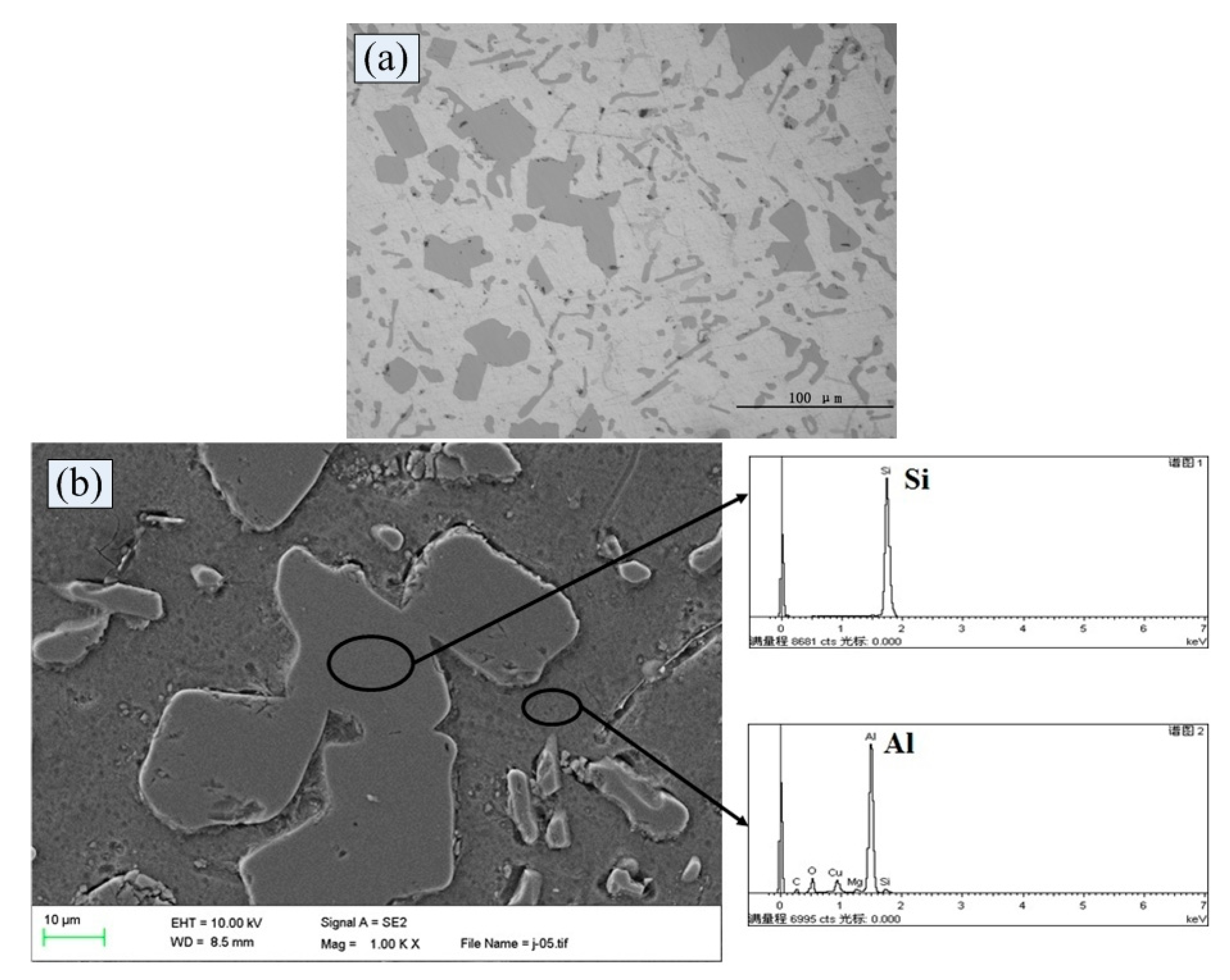
The selected Al-Si alloy is a high-silicon aluminum alloy and its chemical composition is listed in Table 1. An Al-Si alloy cylinder liner with a diameter of 110 mm and a wall thickness of 8 mm was equally divided into 40 samples in the circumferential direction; the length of each sample was 9 mm, as shown in Figure 1, its surface morphology is shown in Figure 2. The piston ring is a chromium-based ceramic composite plated (CKS) ring with an outer diameter of 110 mm and a ring height of 3 mm; an equal division of 32 cuts was performed in the circumferential direction. The CKS piston ring is coated by chromium and small Al2O3 ceramic particles on the cast iron substrate, it is obtained by means of layer by layer deposition to embed the Al2O3 particles into the micro crack of chrome layer, the hardness of the selected CKS piston ring is 761 HV0.1, the surface morphology and section morphology are showed in Figure 3.

Table 1.
The chemical compositions of aluminum-silicon (Al-Si) alloy.
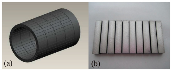
Figure 1.
Schematic diagram of the cylinder liner (a) and samples (b).

Figure 2.
Surface morphology (a) and energy spectrum analysis (b) of Al-Si cylinder liner.
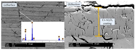
Figure 3.
Surface morphology (a) and section morphology (b) of chromium-based ceramic composite plated (CKS) piston ring.
The surface roughness measurements of piston ring and cylinder liner are both carried out using a Hommel tester-T6000 surface profiler (Hommel, Jena, Germany). The samples are fixed on the profiler stage by a special clamp. The stylus is moved smoothly on the sample surface to be tested. It is not possible to touch the samples during the measurement process. The results are analyzed according to the drawings after the measurement is completed, then the results are marked and printed. The roughness of the ring and original cylinder are 0.24 μm (Ra) and 0.89 μm (Ra), respectively. Ra is called the contour arithmetic mean deviation or the center line average.
2.2. Chemical Etching
The surface of the Al-Si alloy cylinder liner was chemically etched using a 5% NaOH solution. The cylinder liner sample was completely immersed in the alkali etching solution, was removed after the predetermined chemical etching time, and was washed under running water. The chemically etched cylinder liner samples were sequentially soaked in gasoline and alcohol for ultrasonic cleaning to ensure sufficient cleanliness.
Figure 4 shows the surface topographies of the etched Al-Si cylinder liner after different etching time by a Philips-30TMP scanning electron microscope (Philips, Amsterdam, The Netherlands). The aluminum is etched by the solution, resulting in the silicon particles being protruded on the surface; the protrusion height of silicon increases with the increase of etching time.
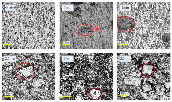
Figure 4.
Surface morphologies of primary and etched Al-Si cylinder liner after different etching time.
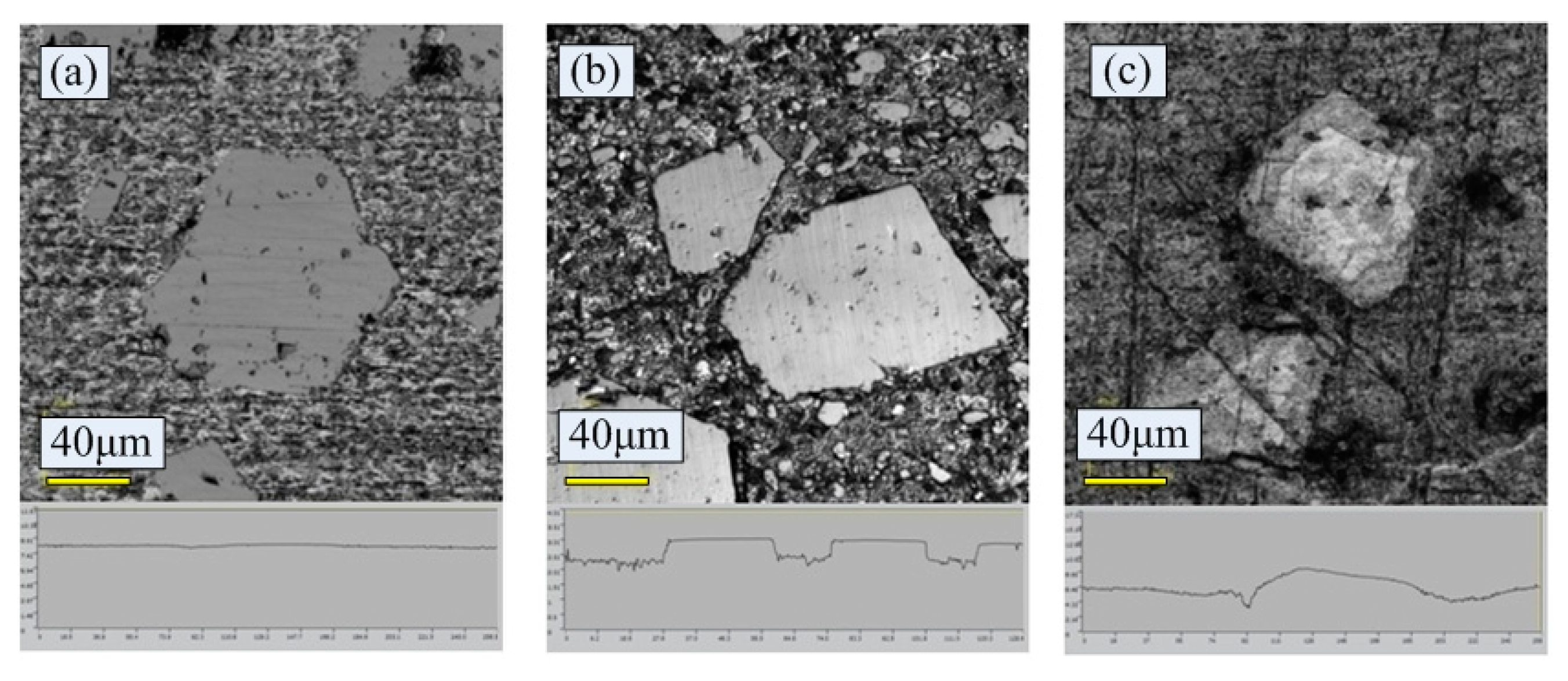
Figure 5 shows the surface morphologies and outlines by an OLYMPUS LEXT OLS4000 laser scanning confocal microscopy (Olympus, Tokyo, Japan). Seen from Figure 5a, the surface of untreated cylinder liner is flat; while chemical etching may scour the aluminum substrate on the surface, which exposes the silicon particles, as shown in Figure 5b.
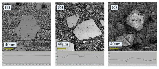
Figure 5.
Polished surface morphologies and outlines of the cylinder liner. (a) Untreated; (b) chemical etching; (c) laser finishing.
2.3. Laser Finishing
The laser finishing of the Al-Si alloy cylinder liner samples was conducted using a CO2 continuous transverse-flow laser. The advantage of this type of laser is that the output laser beam is continuous and the energy is stable, which is beneficial to stably control the surface melting of the aluminum-silicon alloy. The defocus amount is set to 2 mm, and the laser spot diameter is approximately 2 mm.
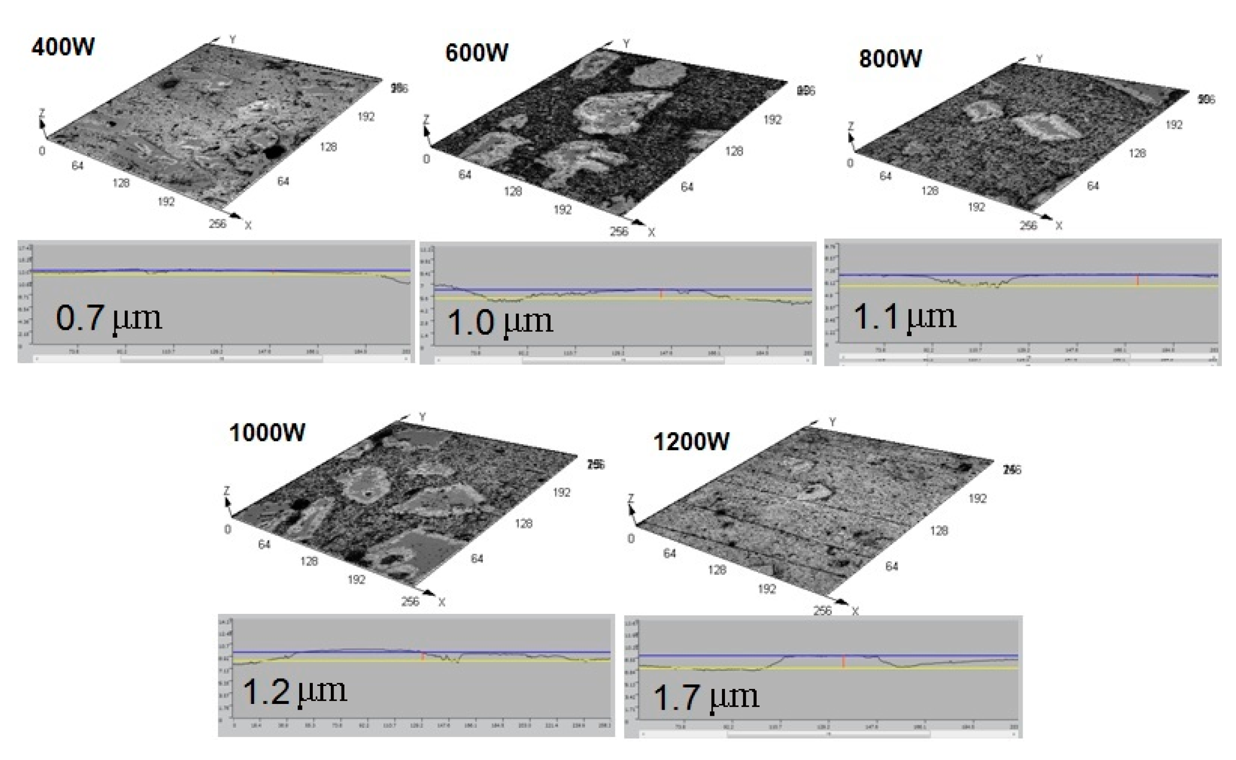
Figure 6 shows the schematic diagram of laser finishing process. The high temperature of laser causes the aluminum layer on the surface of the cylinder liner to melt and evaporate, which exposes the silicon particles. The melting point is higher for the silicon particles than the aluminum matrix. Therefore, the silicon particles melt after the aluminum matrix and when the aluminum melts and evaporates, the exposed silicon particles begin to melt in the convex corners. The laser has instant heating and instantaneous cooling, so the silicon particles are rapidly cooled after being melted, and due to the lowest surface energy principle, the silicon particles are rounded by the surface tension, which reduce the surface energy during the melting and re-cooling molding process. On the premise of a certain material removal rate, a certain surface quality is ensured and free of burrs. The rounded profile of silicon particles can be seen in Figure 5c. The change in the laser power affects the protrusion height of the silicon particles, which also affects the friction performance. Figure 7 shows the surface morphologies and outlines of the Al-Si alloy cylinder liner with different laser power. The protrusion height of the silicon particles increases from 0.7 μm to 1.7 μm with the increase of laser power.
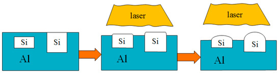
Figure 6.
Laser finishing process of Al-Si alloy cylinder liner.
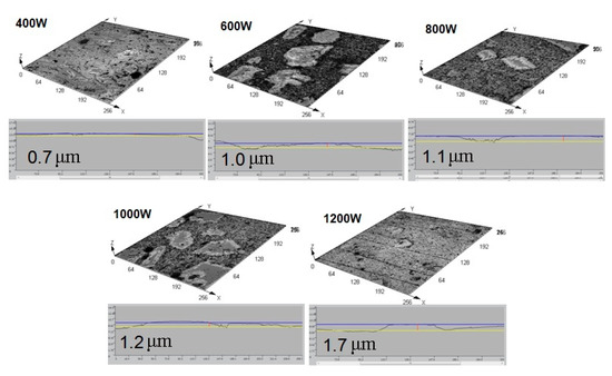
Figure 7.
Surface morphologies and outlines of the cylinder liner with different laser power.
2.4. Wear Tests
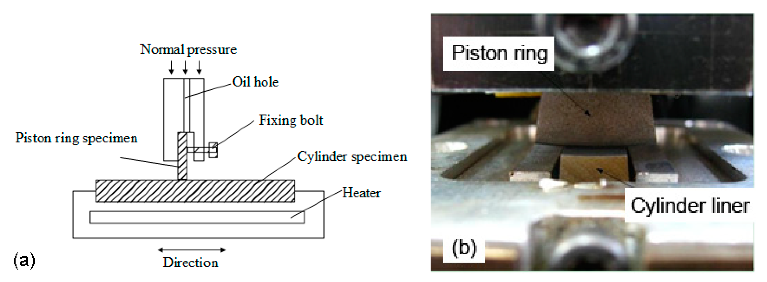
Tribotests are conducted on a reciprocating sliding tribotester as shown in Figure 8. The piston ring sample is fixed in the jag of the upper holder, while the cylinder liner sample is fixed in the heat block, which is dragged by a motor through wheel and nod. The reciprocating stroke length is 30 mm. The tribotester can accommodate a wide range of speeds (5–500 r/min), loads (5–380 MPa), and temperatures (30–300 °C) between the piston ring and cylinder liner. The model parameters used in this study are determined by a large number of previous experiments to simulate the wear performance of the piston rings and cylinder liners under boundary lubrication conditions. The load consisted of two stages, which are running-in stage and steady stage. The first stage is a low load of 5 MPa for 1 h to reduce the effect of burrs on the test repeatability; the second stage is a high load of 20 MPa for 4 h because the maximum explosion pressure of the diesel engine is about 20 MPa. To simulate the surface temperature of the cylinder liner when the first piston ring is near the top dead center (TDC), the test temperature is set to 150 °C. In order to ensure the boundary lubrication state and consider the wear efficiency, the speed is selected as 200 r/min. The lubricating oil is RP-4652D (15W-40/CF-4), which is supplied at a speed of 0.1 mL/min. By the pre-experiments and contact resistance method, the oil film thickness ratio near the top dead center is calculated to be about 0.8 under the condition of this parameters, and the friction coefficient is between 0.1 and 0.15, which is generally considered to be in the boundary lubrication state. Each test is repeated four times to obtain a stable result.
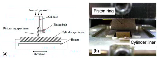
Figure 8.
Diagram of the tribotester (a) and the contact between the piston ring and cylinder liner (b).
The friction coefficient and weight loss are used to determine the friction performance. The friction coefficient is the ratio of the friction to the normal load. The weight loss is the difference in weight before and after the experiment.
3. Experimental Results
3.1. Friction Performance after Chemical Etching
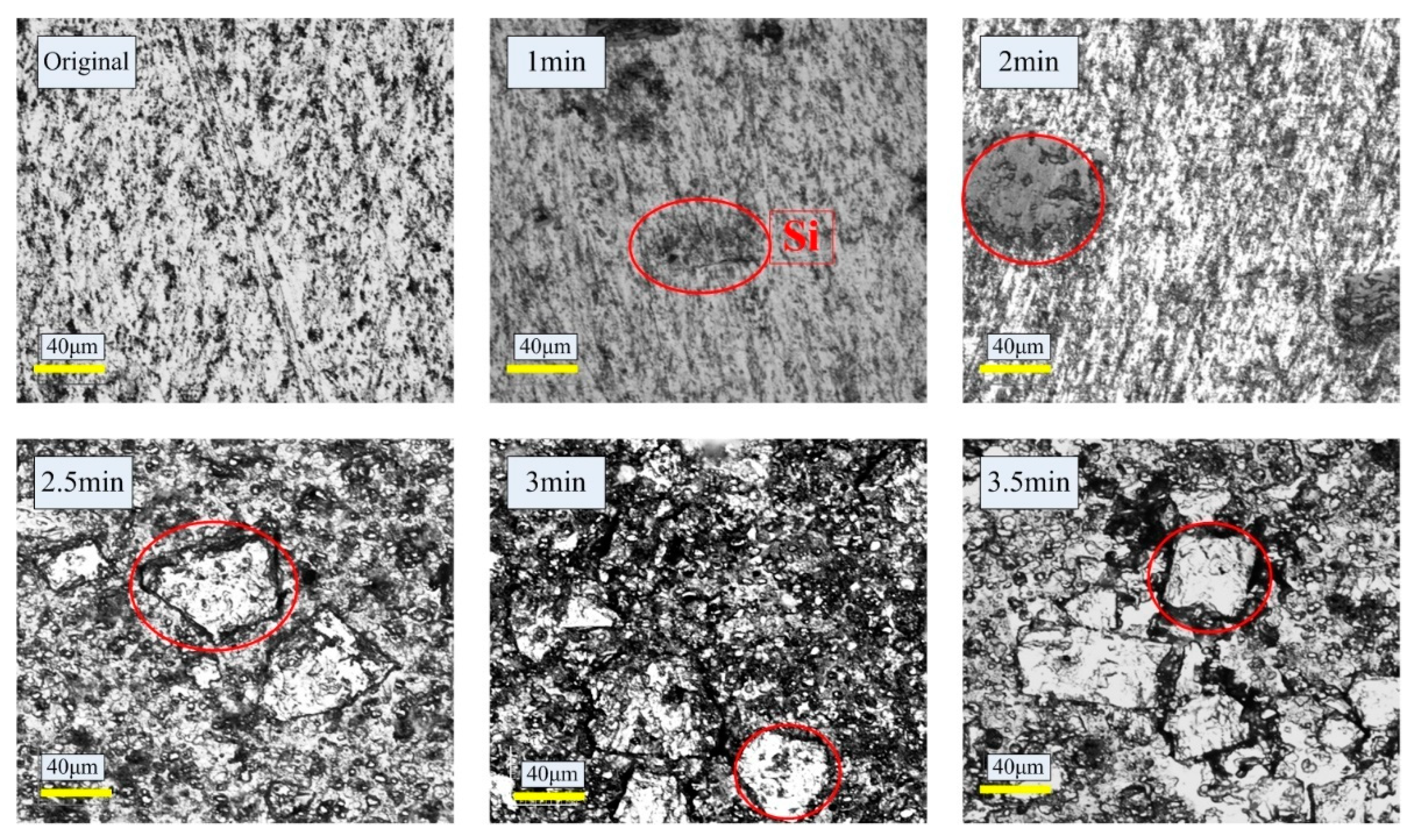
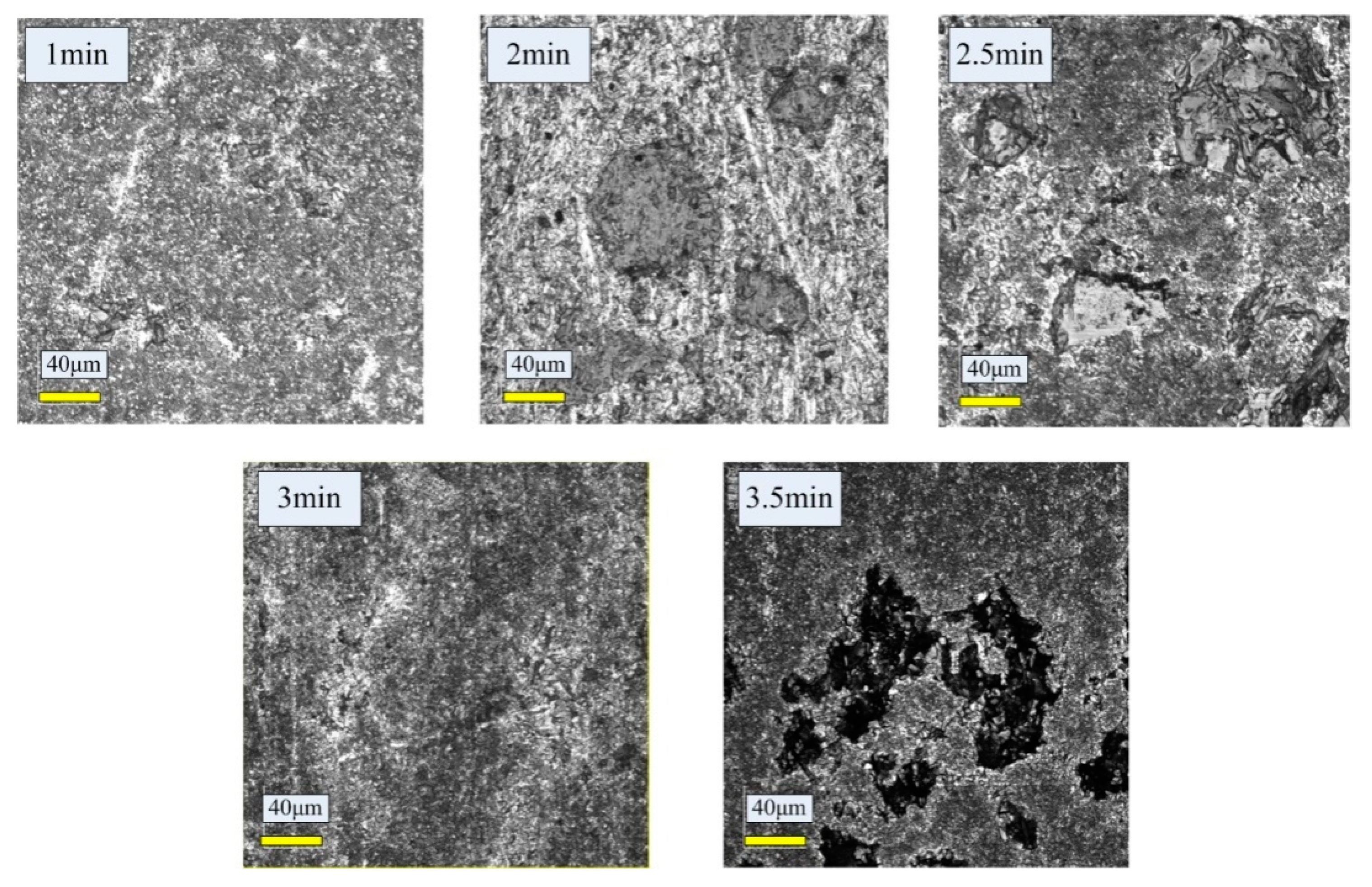
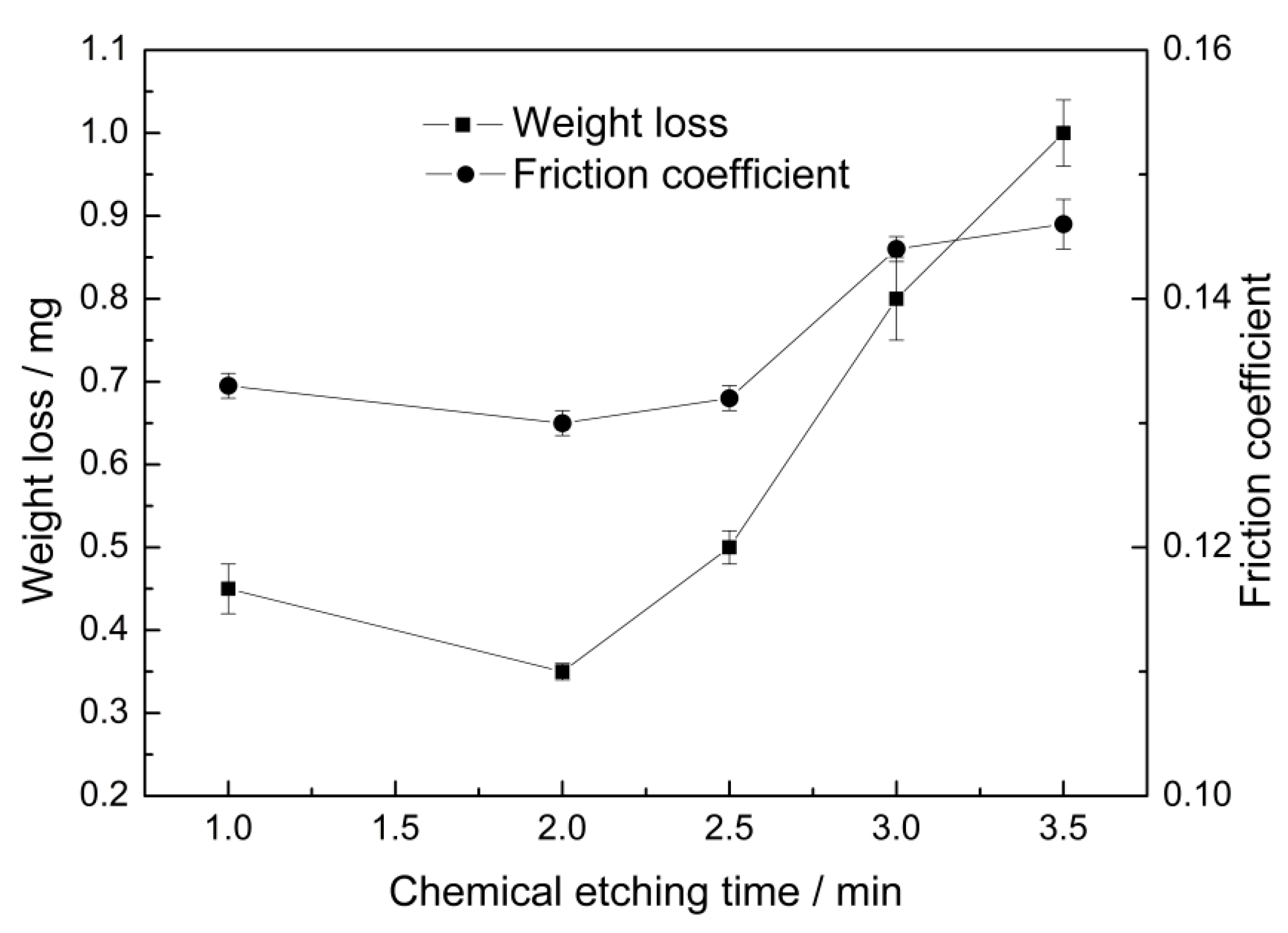
Figure 9 shows the worn surface morphologies of the etched cylinder liner after different etching time. The friction coefficient and weight loss tend to first decrease and then increase with the increase in the chemical etching time, as shown in Figure 10. If the cylinder liner is unetched or the etching time is very short, an insufficient amount of aluminum is removed from the surface to expose the silicon; in contrast, if the etching time is very long, the silicon may easily peel off and abrasive grains form, which would increase the friction coefficient and wear loss. As the etched time increases, the friction coefficient decreases from 0.133 to 0.13, and then increases to 0.146. While the wear loss decreases from 0.45 mg to 0.35 mg, then increases to 1 mg. The friction coefficient and wear amount both reach the minimum value at a chemical etching time of 2 min; the protruding height of the silicon particles is about 1.1–1.2 μm.
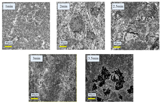
Figure 9.
The worn surface morphologies of the etched cylinder liner after different etching time.

Figure 10.
Effect of chemical etching time on the weight loss and friction coefficient.
3.2. Friction Performance after Laser Finishing
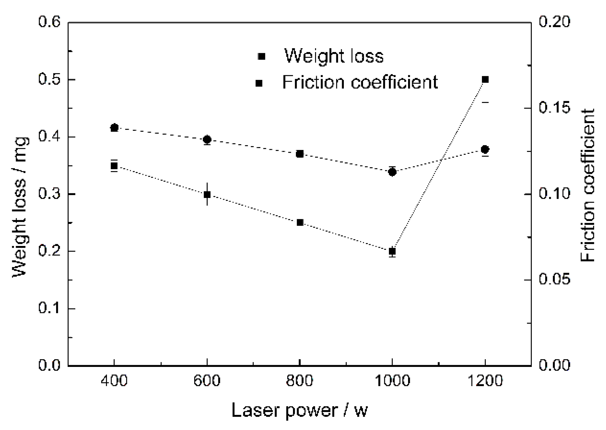
The friction coefficient and weight loss exhibit the same trend as the laser power is increased. When the laser power is very low or very high, the performance is low. If the laser power is low, it cannot effectively make the silicon exposed; if the laser power is high, the silicon may be prone to fall off and became abrasive grains. As the laser power increases, the friction coefficient decreases from 0.138 to 0.11, and then increases to 0.126. While the wear loss decreases from 0.35 mg to 0.2 mg, then increases to 0.5 mg. When the laser power is 1000 W and the according intensity is 31 kW/cm2, the weight loss and the friction coefficient reach the lowest value, as shown in Figure 11. The protrusion height of the silicon particles is about 1.2 μm at this laser power.

Figure 11.
Effect of laser power on the weight loss and friction coefficient.
3.3. Friction Performance of the Two Surface Treatments
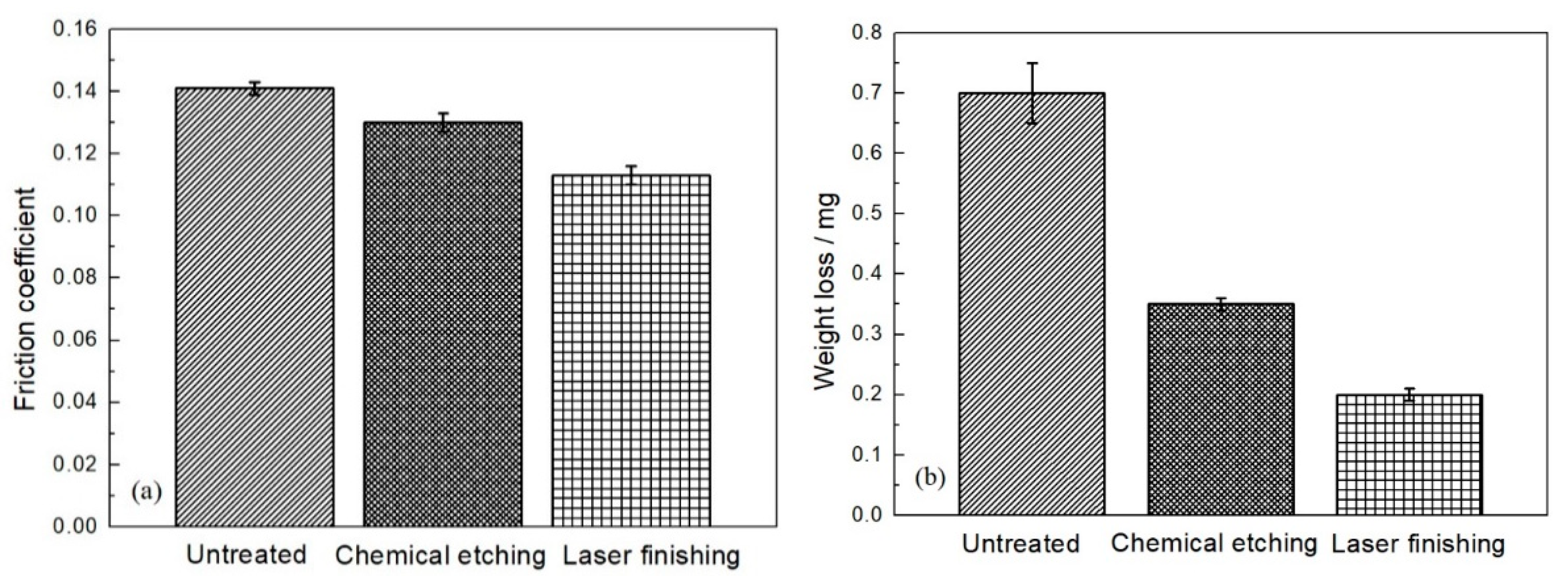
The optimal cylinder liner samples resulting from the two surface treatments are used to compare the friction performance. Figure 12 shows the weight loss and friction coefficients between the piston ring and the cylinder liners with different surface treatments. The largest friction coefficient of 0.14 is observed for the untreated cylinder, because the aluminum is in direct with the piston ring during friction process, so it is prone to transfer to the surface of piston ring, resulting in the adhesion wear and a high friction coefficient. The friction coefficients of the cylinders with the two surface treatments methods are lower than that of the untreated cylinder because the protrusion of the silicon particles reduces the adhesive wear. The laser finishing treatment results in the smallest friction coefficient of 0.11 because the silicon particles are rounded and the stress concentration is reduced.
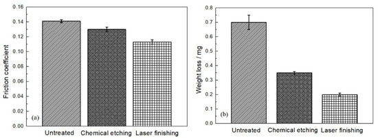
Figure 12.
Weight loss and friction coefficient for different surface treatments. (a) Friction coefficient; (b) weight loss.
The weight loss results exhibit the same trend as the friction coefficient; the weight loss is lowest for the laser finishing treatment at 0.2 mg. The surface of the cylinder liner after chemical etching is sharp and easily breaks when applying friction. Abrasive grains are formed and scour the surface, resulting in higher weight loss than for the laser finishing treatment.
3.4. Surface Morphology of the Piston Ring
Figure 13 shows the surface morphology before and after the CKS piston ring is worn. It can be seen that the dark ceramic particles are inlaid in the chrome layer, and the vertical stripes are the original machining marks of the piston ring in the circumferential direction (Figure 13a). When the piston ring is worn against the untreated Al-Si cylinder liner, a layer of aluminum adheres to the surface of the piston ring and the ceramic particles are covered by the plastic flow layer; this indicates that adhesive wear occurred on the piston ring surface (Figure 13b). When worn against the cylinder liner after chemical etching, the piston ring exhibits damage marks on the surface. The surface of the piston ring is easily scratched during the friction due to the sharp edge of the raised silicon particles. The original machining marks are not observed on the worn surface (Figure 13c). When the piston ring is worn against the cylinder liner after laser finishing, the original machining marks are still clearly visible, which indicates that only slight wear occurs (Figure 13d).
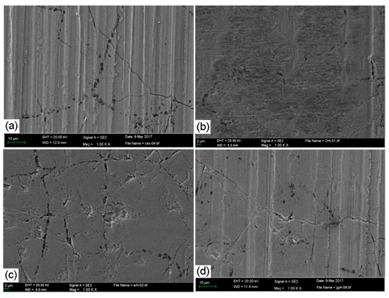
Figure 13.
Surface morphologies of the CKS piston ring before and after wear. (a) Unworn; (b) worn against an untreated Al-Si cylinder liner; (c) worn against an untreated Al-Si cylinder liner after chemical etching; (d) worn against an untreated Al-Si cylinder liner after laser finishing.
4. Simulation
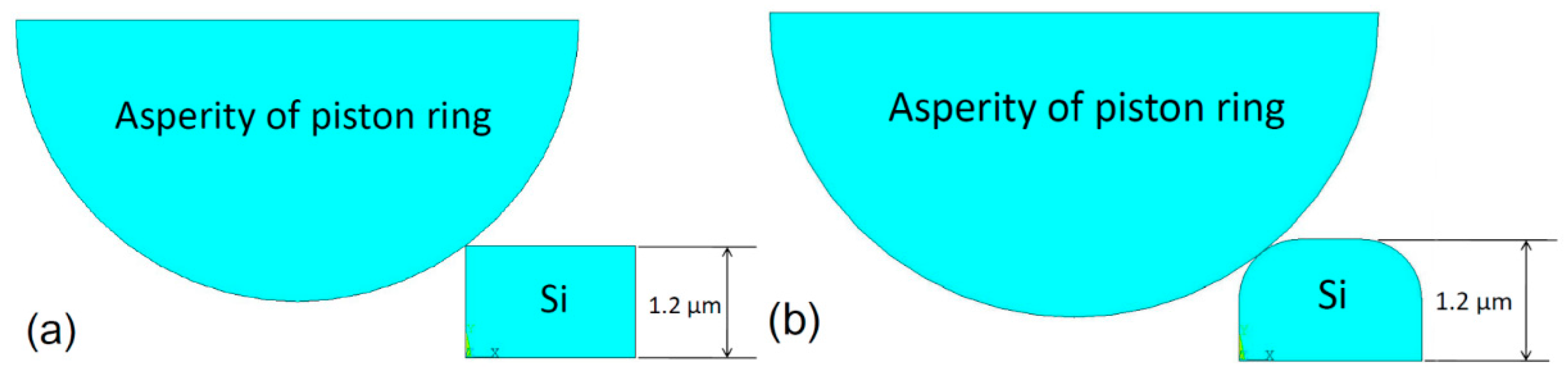
The contact wear models of the piston ring and the chemically etched and laser-finished cylinder liners are created to compare the contact stress of the silicon particles in a static state, as shown in Figure 14. Most scholars have studied the asperities and assumed that the asperities shapes are hemispherical (3D) or semicircular (2D) [30,31]. This work also assumes that the piston ring asperities are semicircular. The material property parameters are shown in Table 2.
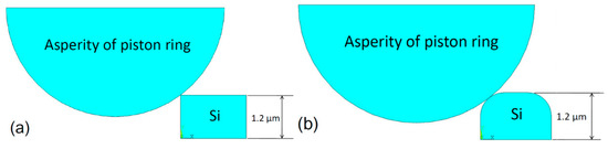
Figure 14.
Geometric representation of the contact model. (a) Chemical etching model; (b) laser finishing model.
Table 2.
Material property parameters.
The following assumptions are made for the stress model:
- The asperity of the piston ring only contacts the silicon particles.
- The piston ring/silicon particle contact is rigid to flexible so that the piston ring elements cannot penetrate the silicon.
- The wear depth is the same for the two cases and a given downward displacement of 0.05 μm is applied to the piston ring.
The boundary conditions for the stress model are as follows:
- The bottom nodes of the silicon particle are fixed:where Ux and Uy are the degrees of freedom along the x- and y-direction.Ux = Uy = 0
- The downward displacement of the piston ring is:Uy = −0.05 μm
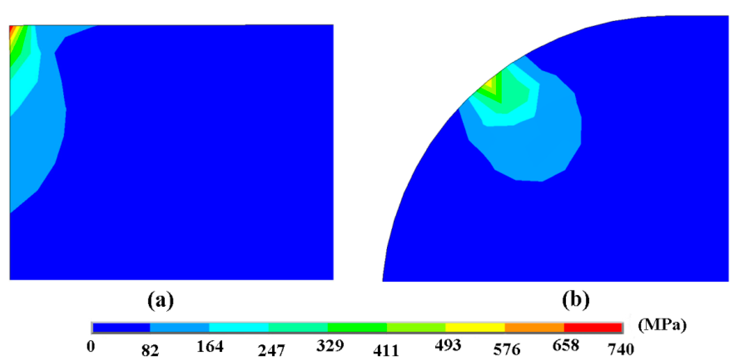
Figure 15 shows the contact stress of the silicon particles at the contact positions for chemical etching and laser finishing. The maximum stress occurs at the corners of the silicon particles and is 737 MPa after chemical etching, whereas the edges of the silicon particles are relatively smooth after laser finishing and the maximum stress is 561 MPa, exhibiting less stress. During the contact process, the silicon particles on the surface of the cylinder liner are subjected to greater stress after chemical etching; therefore, wear is more likely to occur and the weight loss of the cylinder liner is larger than for the laser finishing.

Figure 15.
Contact stress distribution of silicon particles at the contact areas. (a) Chemical etching model; (b) laser finishing model.
5. Wear Mechanism
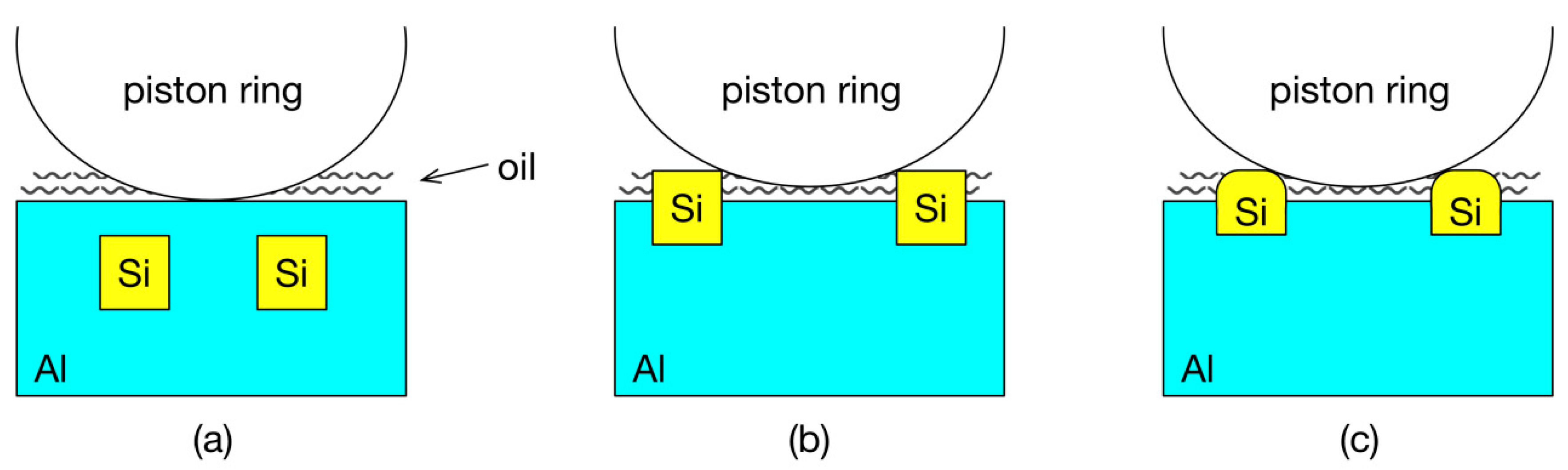
Figure 16 shows the piston ring-cylinder liner wear mechanism after different surface treatments. In the untreated cylinder liner, the silicon particles are integrated into the aluminum matrix, so a layer of aluminum is in direct contact with the piston ring and is prone to adhesive wear, thus resulting in a higher friction coefficient and weight loss. When the cylinder liner is treated by chemical etching, the silicon particles protrude from the surface. The hard silicon particles prevent the direct contact between the piston ring and the aluminum, which reduces the adhesive wear. Meanwhile, the relatively concave aluminum base can retain the lubricating oil. When the piston ring reaches the top dead center (TDC), it is not conducive to the formation of oil film due to the low sliding speed, high gas pressure and high temperature, which is under the boundary lubrication condition. Therefore, the wear of the cylinder liner is large at the top dead center. After the Al-Si alloy is treated by chemical etching or laser finishing, the protruded hard silicon particles could bear the heavy load, while the relative concave surface of aluminum could retain the oil. When the piston ring is in the middle of the cylinder liner, the oil could be stored in the concave surface; when the piston ring reaches the TDC, the lubrication condition is severe, and the oil obtained in the concave surface could help to form oil film to enhance the lubrication [32]. Laser finishing not only results in the protrusion of the silicon particles but also in rounded edges, which reduces the stress concentration. Therefore, the friction coefficient and the weight loss exhibit better performances for the laser finishing than the chemical etching.
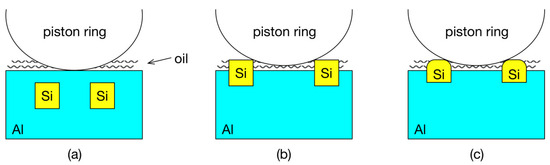
Figure 16.
Schematic diagram of the wear mechanism. (a) Untreated; (b) chemical etching; (c) laser finishing.
6. Conclusions
The effects of chemical etching and laser finishing techniques on the friction performance of an Al-Si cylinder liner were investigated by a reciprocating wear test. The following conclusions were drawn:
- The friction coefficient and weight loss of the Al-Si cylinder liner tend to decrease first and then increase with the increase in the chemical etching time; the optimum etching time is 2 min.
- As the laser power increases, the friction coefficient and weight loss also decrease first and then increase; the optimum laser power is 1000 W.
- Chemical etching and laser finishing both remove the surface aluminum layer and result in the protrusion of the silicon particles, which bear the load. Under the boundary lubrication state, the lubricating oil retained in the concave surface could help to form oil film to enhance the lubrication.
- Unlike chemical etching, laser finishing results in rounded edges of the silicon particles, which decreases the stress concentration. As a result, the surface friction performance of the Al-Si cylinder liner is better when laser finishing is used.
Author Contributions
Data curation, C.L.; Investigation, Z.M.; Project administration, X.H.; Resources, R.H.; Supervision, J.X.; Validation, Y.S.; Writing—original draft, F.D.
Funding
This research was supported by the China Postdoctoral Science Foundation (2017M611209) and Natural Science Foundation of Liaoning Province (20170540083).
Conflicts of Interest
The authors declare no conflict of interest.
References
- Dwivedi, D.K. Adhesive wear behaviour of cast aluminium-silicon alloys: Overview. Mater. Des. 2010, 31, 2517–2531. [Google Scholar] [CrossRef]
- Shahrbabaki, Z.K.M.; Pahlevani, F.; Gorjizadeh, N.; Hossain, R.; Ghasemian, M.B.; Gaikwad, V.; Sahajwalla, V. Direct transformation of metallized paper into Al-Si nano-rod and Al nano-particles using thermal micronizing technique. Materials 2018, 11, 1964. [Google Scholar] [CrossRef]
- Ni, J.Q.; Yu, M.H.; Han, K.Q. Debinding and sintering of an injection-moulded hypereutectic Al-Si alloy. Materials 2018, 11, 807. [Google Scholar] [CrossRef] [PubMed]
- Chiang, K.T.; Tsai, D.C. Effect of silicon particles on the rapidly resolidified layer of Al-Si alloys in the electro discharge machining process. Int. J. Adv. Manuf. Technol. 2008, 36, 707–714. [Google Scholar] [CrossRef]
- Chen, C.; Lu, C.Y.; Feng, X.M.; Shen, Y.F. Effects of annealing on Al-Si coating synthesised by mechanical alloying. Surf. Eng. 2017, 33, 548–558. [Google Scholar] [CrossRef]
- Burkinshaw, M.; Neville, A.; Morina, A.; Sutton, M. ZDDP and its interactions with an organic antiwear additive on both aluminium-silicon and model silicon surfaces. Tribol. Int. 2014, 69, 102–109. [Google Scholar] [CrossRef]
- Ye, H.Z. An overview of the development of Al-Si-Alloy based material for engine applications. J. Mater. Eng. Perform. 2003, 12, 288–297. [Google Scholar] [CrossRef]
- Elmadagli, M.; Perry, T.; Alpas, A.T. A parametric study of the relationship between microstructure and wear resistance of Al-Si alloys. Wear 2007, 262, 79–92. [Google Scholar] [CrossRef]
- Chen, M.; Meng-Burany, X.; Perry, T.A.; Alpas, A.T. Micromechanisms and mechanics of ultra-mild wear in Al-Si alloys. Acta. Mater. 2008, 56, 5605–5616. [Google Scholar] [CrossRef]
- Slattery, B.E.; Perry, T.; Edrisy, A. Microstructural evolution of a eutectic Al-Si engine subjected to severe running conditions. Mat. Sci. Eng. A. 2009, 512, 76–81. [Google Scholar] [CrossRef]
- Slattery, B.E.; Edrisy, A.; Perry, T. Investigation of wear induced surface and subsurface deformation in a linerless Al-Si engine. Wear 2010, 269, 298–309. [Google Scholar] [CrossRef]
- Zandrahimi, M.; Rezvanifar, A. Investigation of dislocation characterisation in worn Al-Si alloys with different sliding speeds using X-Ray diffraction. Tribol. Lett. 2012, 46, 255–261. [Google Scholar] [CrossRef]
- Dwivedi, D.K. Wear behaviour of cast hypereutectic aluminium silicon alloys. Mater. Des. 2006, 27, 610–616. [Google Scholar] [CrossRef]
- Shen, Y.; Lv, Y.T.; Li, B.; Huang, R.X.; Yu, B.H.; Wang, W.W.; Li, C.D.; Xu, J.J. Reciprocating electrolyte jet with prefabricated-mask machining micro-dimple arrays on cast iron cylinder liner. J. Mater. Process. Tech. 2019, 266, 329–338. [Google Scholar] [CrossRef]
- Mansuri, M.; Hadavi, S.M.M.; Zare, E.; Nabi, M.M. Thermal fatigue behaviour of Al-Si coated Inconel 713LC. Surf. Eng. 2016, 32, 201–206. [Google Scholar] [CrossRef]
- Viswanathan, A.; Sastikumar, D.; Kamachimudali, U.; Kumar, H.; Nath, A.K. TiC reinforced composite layer formation on Al-Si alloy by laser processing. Surf. Eng. 2007, 23, 123–128. [Google Scholar] [CrossRef]
- Meng, X.C.; Liu, B.; Luo, L.; Ding, Y.; Rao, X.X.; Hu, B.; Liu, Y.; Lu, J. The Portevin-Le Chatelier effect of gradient nanostructured 5182 aluminum alloy by surface mechanical attrition treatment. J. Mater. Sci. Technol. 2018, 34, 2307–2315. [Google Scholar] [CrossRef]
- Li, C.D.; Li, B.; Shen, Y.; Jin, M.; Xu, J.J. Effect of surface chemical etching on the lubricated reciprocating wear of honed Al–Si alloy. Proc. IMechE. Part J J. Eng. Tribol. 2018, 232, 722–731. [Google Scholar] [CrossRef]
- Riahi, A.R.; Perry, T.; Alpas, A.T. Scuffing resistances of Al-Si alloys: effects of etching condition, surface roughness and particle morphology. Mater. Sci. Eng. A. 2003, 343, 76–81. [Google Scholar] [CrossRef]
- Das, S.; Perry, T.; Biswas, S.K. Effect of surface etching on the lubricated sliding wear of an eutectic aluminium-silicon alloy. Tribol. Lett. 2006, 21, 193–204. [Google Scholar] [CrossRef]
- Cai, Z.H.; He, J.W.; Di, Y.L.; Zhang, P. Microstructure and high temperature wear resistance of laser quenching and ion sulphidizing composite layer on cylinder inwall. Heat. Treat. Metal. 2011, 36, 55–59. [Google Scholar]
- Ghosh, K.; Mccay, M.H.; Dahotre, N.B. Formation of a wear resistant surface on Al by laser aided in-situ synthesis of MoSi2. J. Mater. Process. Tech. 1999, 88, 169–179. [Google Scholar] [CrossRef]
- Tomida, S.; Nakata, K.; Shibata, S. Improvement in wear resistance of hyper-eutetic Al-Si cast alloy by laser surface remelting. Surf. Coat. Technol. 2003, 169, 468–471. [Google Scholar] [CrossRef]
- Sušnik, J.; Šturm, R.; Grum, J. Influence of laser surface remelting on Al-Si alloy properties. Strojniški vestnik-J. Mech. Eng. 2012, 58, 614–620. [Google Scholar] [CrossRef]
- Gao, J.F.; Suo, J.P. Preparation and characterization of the electrodeposited Cr–Al2O3/SiC composite coating. Appl. Surf. Sci. 2011, 257, 9643–9648. [Google Scholar] [CrossRef]
- Jang, J.H.; Joo, B.D.; Lee, J.H.; Moon, Y.H. Effect of hardness of the piston ring coating on the wear characteristics of rubbing surfaces. Met. Mat. Int. 2009, 15, 903–908. [Google Scholar] [CrossRef]
- Zhu, F.; Xu, J.J.; Han, X.G.; Shen, Y.; Jin, M. Tribological performance of three surface-modified piston rings matched with chromium-plated cylinder liner. Ind. Lubr. Tribol. 2017, 69, 276–281. [Google Scholar] [CrossRef]
- Shen, Y.; Yu, B.H.; Lv, Y.T.; Li, B. Comparison of heavy-duty scuffing behavior between chromium-based ceramic composite and nickel-chromium-molybdenum-coated ring sliding against cast iron liner under starvation. Materials 2017, 10, 1176. [Google Scholar] [CrossRef]
- Shen, Y.; Xu., J.J.; Jin, M.; Yuan, X.S.; Wang, J.P.; Liu, Y.; Zhu, F.; Wang, Z.Q. Scuffing behavior of CKS piston ring with alloy cast iron cylinder liner. Lubr. Eng. 2014, 39, 40–43. [Google Scholar]
- Liu, W.Q.; Zhang, J.H.; Hong, J.; Zhu, L.B. Elastic contact model of elliptical parabolic asperity. J. Xi’an Jiaotong. Univ. 2015, 49, 34–40. [Google Scholar]
- Zhao, Y.W.; Maietta, D.M.; Chang, L. An asperity microcontact model incorporating the transition from elastic deformation to fully plastic flow. J. Tribol. 2000, 122, 86. [Google Scholar] [CrossRef]
- Sun, T.F.; Guo, M.X.; Zhu, H.Y.; Chen, D.H.; Sun, Y.H.; Wang, F.D. The friction wearing properties research of high-silicon aluminium alloy cylinder sleeve. Vehicle. Power. Tech. 2007, 2, 14–18. [Google Scholar]


© 2019 by the authors. Licensee MDPI, Basel, Switzerland. This article is an open access article distributed under the terms and conditions of the Creative Commons Attribution (CC BY) license (http://creativecommons.org/licenses/by/4.0/).