Abstract
Edge cracking severely limits the rolling yield of magnesium alloy plates. A novel lattice severe deformation rolling (LSDR) process using corrugated rolls is proposed to suppress edge cracking. Numerical simulations, rolling experiments, and microstructural analyses were conducted, with results compared to conventional flat rolling (FR), to elucidate the suppression mechanism. LSDR induces a multi-peak stress distribution and restricts metal flow, thereby reducing additional stresses responsible for edge cracking. Deformation heat generated in local severe deformation zones compensates for thermal loss, alleviates the temperature gradient between the plate edge and center, and enhances overall plasticity. According to the Cockcroft–Latham fracture criterion, LSDR effectively limits damage growth and confines damage within a single lattice, suppressing crack propagation, whereas FR produces damage values far exceeding the critical value of 0.43. Furthermore, fine grains formed in severe deformation zones, together with dislocation entanglement induced by twinning, impede crack propagation. This work demonstrates the effectiveness of LSDR and provides a new approach for mitigating edge cracking in rolled metal plates.
1. Introduction
Magnesium alloys have outstanding advantages such as low density, high specific strength, dimensional stability, good vibration resistance, strong electromagnetic shielding, excellent biocompatibility, and easy recyclability, making them important structural materials in industries such as aerospace, automobiles, and electronic information [1,2,3,4]. However, due to its low-symmetry, closely arranged hexagonal structure, the openable slip system is limited, resulting in low room-temperature plasticity and poor formability, making it difficult to ensure high forming quality during large deformations [5,6,7].
Rolling is a widely adopted method for magnesium alloy plate preparation due to its high precision, efficiency, stable quality, and suitability for large-scale production. However, during the rolling process, magnesium alloy plates exhibit a significant damage gradient along the width direction. Edge cracking tends to occur in the edge regions of the plate, where material flow is relatively unrestricted. The factors influencing edge cracking are numerous, including rolling temperature, reduction schedule, strain rate, and others, often resulting from the combined effects of multiple factors. Generally, rolling of magnesium alloys typically requires heating to activate prismatic slip systems. Slip systems on prismatic and pyramidal planes begin to activate during rolling above 200 °C. Thirumurugan et al. [8] investigated the influence of temperature on the microstructure during magnesium alloy rolling and found that grains are fully refined in regions above the recrystallization temperature; in lower-temperature regions, deformation is dominated by twinning, with shear bands forming at twinning concentrations, and the extension of shear bands leads to edge cracking. When the actual rolling temperature is controlled between 350 °C and 400 °C, relatively ideal yield rates and grain microstructures can be achieved. Li et al. [9] suggested that during the rolling process of magnesium alloy sheets, uneven heat dissipation occurs at the edges due to thermal convection with air. This temperature difference leads to variations in material flow between the center and edges of the sheet, generating additional tensile stress at the edges. When this tensile stress becomes excessive, edge cracking occurs. The rolling reduction schedule also directly influences the generation of edge cracks and the resulting microstructure and mechanical properties. The reduction schedule includes both the maximum deformation rate per rolling pass and the cumulative deformation rate across the rolling process. Under a constant total reduction rate, fewer rolling passes result in greater damage at the edges of AZ31 magnesium plates, along with increased and rapidly expanding edge cracks. Therefore, a rolling strategy involving multiple passes with smaller reductions per pass is typically adopted. However, if the reduction per pass is too small, it increases the number of rolling passes and reduces production efficiency [10]. Del et al. [11] found that appropriate pass selection can continuously refine grains, while rotational dynamic recrystallization promotes matrix grain orientations favorable for subsequent deformation, enabling magnesium alloys to achieve high-reduction rolling without crack formation. The microstructure of rolled magnesium alloys is influenced by strain rate; different strain rates affect grain size, twinning density, and recrystallization behavior, thereby influencing plate crack generation to a certain extent [12]. Liu et al. [13] found that at a constant strain rate, the critical strain increases with rising temperature. Conversely, at a constant temperature, the critical strain decreases as the strain rate increases. This indicates a correlation between the critical fracture strain during hot rolling of magnesium alloys and both strain rate and temperature. Utsunomiya et al. [14,15,16] applied high-strain-rate rolling to AZ31, AZ31B, and AZ80 magnesium alloy sheets and found that, with appropriate parameter adjustments, fine grains with an average grain size of 2–3 μm could be obtained under a single-pass reduction of 60%. Zhu et al. [17,18] investigated medium-to-high-strain-rate rolling of ZK60 magnesium alloy and discovered that, at temperatures of 250 °C, 300 °C, 350 °C, and 400 °C with average strain rates ranging from 7.8 s−1 to 9.6 s−1, ultrafine grains with average sizes of 0.4–2.5 μm could be produced. Jiang et al. [19] conducted high-strain-rate rolling on ZM61 magnesium alloy plates at 300 °C with an average strain rate of 9.1 s−1 after pre-rolling; at a single-pass reduction of 80%, plates with an average grain size of 0.8 μm and excellent mechanical properties were achieved. It can be seen that high-strain-rate rolling overcomes the limitations of the processing window in conventional rolling.
In efforts to mitigate rolling edge cracking, Jia et al. [20] pre-compressed magnesium alloy billets along the transverse direction before hot rolling. Their findings indicated that this method reduced the number of shear bands, thereby decreasing edge cracking. Sun et al. [21] introduced pulsed current-assisted rolling based on the cold rolling of AZ31B magnesium alloy. They observed that the application of pulsed current refined the grain structure and influenced the quantity and configuration of shear bands during rolling. This resulted in a reduction in the strain experienced by individual shear bands, which in turn helped suppress the formation of edge cracks. Huang et al. [22] demonstrated that vertical rolling can effectively reduce edge cracking in AZ31B magnesium alloy. This is attributed to the ability of vertical rolling to activate a greater number of slip systems in the magnesium alloy, thereby enhancing its rolling performance. Wang et al. [23] employed a method where two preheated hard alloy backing plates were placed on the upper and lower surfaces of the magnesium alloy plate. By co-rolling the magnesium alloy together with these backing plates, heat dissipation from the magnesium alloy was significantly reduced. Additionally, this process transformed the shear stress on the plate surface into compressive stress, substantially mitigating edge cracking. Guo et al. [24] conducted large-strain hot rolling of magnesium alloy plates and found that as the strain rate increased, dynamic recrystallization (DRX) behavior was enhanced, while the grain size of the original coarse grains remained largely unchanged, and plasticity improved significantly. During high-speed rolling, most of the deformation energy serves as the driving force for recrystallization nucleation and grain growth. In contrast, during low-speed rolling, part of the deformation energy is absorbed by twinning and stored as lattice defects, while the remainder is released in the form of crack propagation. However, this method can only reduce edge cracking under conditions of high temperature, high strain rate, and large reductions, imposing high demands on rolling equipment and heating conditions. Common measures to suppress edge cracking either involve altering the material’s stress state or distribution through pre-rolling or rely on setting process parameters and providing necessary temperature conditions to improve the plasticity of magnesium alloys, both of which are typically challenging to achieve.
In recent years, the author has proposed the lattice severe deformation rolling (LSDR) principle. By employing specially designed corrugated rolls, this method imposes a strongly heterogeneous deformation with a lattice-like distribution on magnesium alloy plates, even under small reductions. This significantly improves the stress state of the plates, particularly in the edge regions, and effectively suppresses edge cracking during rolling. Building on this principle, this study conducts a comprehensive analysis of magnesium alloy plates processed via LSDR using numerical simulations, rolling experiments, and microstructural observations. A comparison is made with the FR process to investigate the underlying mechanism of edge crack inhibition.
2. Materials and Methods
The principle of LSDR is illustrated in Figure 1. The upper roll features a surface with a regular pattern of protruding structures formed by sinusoidal waves distributed along both the circumferential and axial directions, while the lower roll remains flat. The corrugated roll applies a strongly heterogeneous and unevenly distributed deformation to one side of the magnesium alloy plate, inducing intense localized plastic compression. This surface structure is imprinted onto the plate, forming corresponding indentations. Each indentation creates a localized area of severe heterogeneous deformation, with the most intense deformation occurring at the bottom of these zones. However, since these depressions are formed by the interweaving of sine curves, they do not induce stress concentration. Consequently, after rolling, the magnesium alloy plate exhibits pronounced plastic deformation at positions corresponding to the peaks of the roll surface waves, forming a lattice-like distribution across the plate. The peak and valley morphologies exhibited by the deformed material are described in accordance with the corresponding features of the roll surface, and all subsequent descriptions will be based on this. Each severe deformation zone is isolated from others by ridges corresponding to the troughs on the roll surface, confining the localized severe deformation within individual zones. In this process, the sheet edge is divided into several small lattice zones. The heterogeneous deformation confines metal flow to localized areas, and with the wrapping and support from the roll, no large tensile stress zones are generated. This effectively constrains metal flow and successfully suppresses edge cracking.
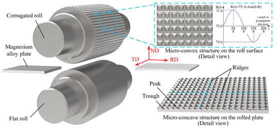
Figure 1.
Lattice severe deformation rolling diagram.
This study investigates the effect of the LSDR principle on edge crack suppression through a combination of numerical simulation and rolling experiments, comparing it with the FR process. The rolling equipment is shown in Figure 2. The experimental material is commercial AZ31B magnesium alloy, with its main chemical composition listed in Table 1. The samples measure 100 mm in length, 60 mm in width, and 5 mm in thickness. The corrugated roll has an average radius of 75 mm, with a sinusoidal wave amplitude of 0.4 mm and a wavelength of 6.28 mm. Its surface corrugations follow a sinusoidal pattern, with identical parameters in both directions. The flat roll also has a radius of 75 mm. The rolling speed is 0.15 m/s, and the reduction rate is 45%, achieved in a single rolling pass. Prior to rolling, the billet was placed in a tube furnace at 400 °C for 30 min under vacuum conditions. During rolling, the plate was quickly transferred from the furnace to the rolling mill to ensure a rolling temperature of 400 °C, while the rolls remained at room temperature (20 °C).
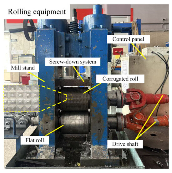
Figure 2.
Rolling equipment.

Table 1.
Chemical compositions of AZ31B magnesium alloy (wt. /%).
The numerical simulation was conducted using 2022 version of the ABAQUS software to analyze the stress evolution in magnesium alloy plates after single-pass rolling and its impact on rolling damage. In the thermo-mechanical coupled explicit dynamic analysis, since the primary deformation occurs in the magnesium plate, the plate was modeled as an elastoplastic body, while the upper and lower rolls were defined as rigid bodies. The rolls were assigned a specific heat capacity of 0.468 J/(g·°C). Contact between the rolls and the plate was defined using the penalty contact method, with Coulomb friction coefficients of 0.3 for the flat roll and 0.35 for the corrugated roll [25]. The magnesium alloy plate had a specific heat capacity of 1.26 J/(g·°C) and was heated to an initial temperature of 400 °C, whereas the initial temperature of the rolls and the ambient environment was 20 °C. Heat transfer between the plate and the rolls was modeled with a heat transfer coefficient of 1000 W/(m2·°C), and convective heat transfer to the surrounding air was included with a coefficient of 20 W/(m2·°C). The plate was meshed with hexahedral elements, with a minimum element size of 0.25 mm to ensure both computational accuracy and efficiency in the finite element analysis. The flow stress equation of the AZ31B magnesium alloy plate was derived from the hot compression experiments in relevant literature [26,27]. To obtain the stress distribution on the surface pattern of the AZ31B magnesium alloy plate during the rolling process, data were sequentially extracted along the mesh nodes to form three paths each in the rolling direction (RD) and the transverse direction (TD) for recording the stress variations at various points throughout the rolling process. Along the RD, the two selected side paths correspond to the peaks and valleys closest to the plate edge under LSDR processing, while the central path is positioned at the peak and valley in the midsection of the plate. Along the TD, the central path lies within the middle of the rolling deformation zone, with the other two paths located near the edges of the deformation zone. The paths for damage values were selected in the regions nearest the plate edges, where damage was most severe.
The rolling experiments were performed on a custom-built two-high experimental mill. The distribution and morphology of cracks on the plates were examined after a single rolling pass. Metallographic specimens measuring 16 mm × 10 mm were extracted from the edge of the rolled magnesium alloy plates along the RD. After polishing and etching, the evolution of their internal microstructure was observed using a Leica DM4M optical microscope (Leica Microsystems GmbH, Wetzlar, Germany).
3. Results and Discussion
3.1. Three-Directional Stress Analysis in the Deformation Zone
The variation and distribution of RD stress along the RD path in the surface deformation region of the plate in contact with the rolls are shown in Figure 3, where positive values indicate tensile stress and negative values indicate compressive stress. The path distance is divided into three zones: Zone I, Zone II, and Zone III, representing the pre-rolling, rolling, and post-rolling regions, respectively. Due to the unique structure of the corrugated roll, its rolling zone (Zone II) measures 22 mm, which is larger than the 16 mm rolling zone of the flat roll. This results in a longer deformation process under severe deformation rolling compared to flat rolling, leading to smoother and more uniform metal flow, which contributes to improved plate forming quality.
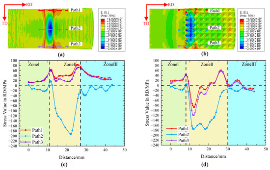
Figure 3.
The RD stress distribution in the RD path in the rolling deformation zone. (a) Stress contour distribution for the FR process, (b) stress contour distribution for the LSDR process, (c) stress curves for the FR process, (d) stress curves for the LSDR process.
For the FR process, as the plate gradually enters the rolls, the applied stress first increases and then decreases. At approximately 11.5 mm, the stress on Path1 and Path3 peaks at 63.6 MPa, while the stress on Path2 reaches 18.5 MPa. This is because the plate has just been bitten into the rolls, and its speed is lower than the roll speed, resulting in higher rolling-direction stress. Subsequently, under the pressure of the rolls, the stress on Path1 decreases to 18.4 MPa around 14.2 mm, and Path3 decreases to 14.2 MPa. Between 14.2 mm and 21.8 mm, Path1 and Path2 experience a complex stress state. Meanwhile, Path2 is surrounded and supported by the surrounding material, restricting its plastic flow, causing the stress to continuously decrease and reach −192 MPa at the 21.8 mm position. After reaching 21.8 mm, the plate enters the forward slip zone of rolling, and stress begins to rise. Path1 and Path2 reach peak stresses of 83.5 MPa and 72.2 MPa, respectively, at 25.5 mm, after which they gradually exit the rolls. Path2 exits the rolls around 27 mm and subsequently exhibits stress fluctuations between 0 MPa and −20 MPa due to elastic recovery and residual stress effects. Throughout the entire rolling zone, both Path1 and Path2 remain under tensile stress, with average stresses reaching 42 MPa. The maximum tensile stress, reaching up to 85 MPa, occurs in the forward slip zone near the rolling exit. This is attributed to the greater freedom for elongation in the edge material, resulting in tensile stress at the edges during rolling deformation [28]. As shown in Zone II of Figure 3, the presence of tensile stress provides a mechanical condition for the initiation of edge cracks in the plate.
For the LSDR process, due to the special shape of the rolls, the plate begins to deform earlier than in the FR process. However, similar to FR, upon entering the deformation zone, the stresses in Path1 and Path3 first reach peak values at 8.2 mm, measuring 41.1 MPa and 44 MPa, respectively, while the stress in Path2 is 5 MPa. Subsequently, under the influence of the special corrugated structure on the roll surface, the stresses along the three paths in the RD exhibit certain periodic variations. However, as the plate bites into the rolls, the rolling pressure gradually increases, making the periodicity of the stresses along the selected rolling paths less pronounced. Nevertheless, the special periodic fluctuations in stress can still be clearly observed. Under the LSDR process, even at the edge locations, the stresses along Path1 and Path3 turn negative at a distance of 9.6 mm and reach their minimum values at 12 mm, measuring −86.6 MPa and −133.1 MPa, respectively. This indicates a transition from tensile stress to compressive stress along the rolling direction, which significantly differs from the predominantly tensile stress observed at the edges under the FR process. The difference in the minimum stress values between the two edge paths is primarily due to variations in mesh integrity at the edges. At Path1, where the mesh is less complete and the wave peak is closer to the edge, the metal has more room to flow, resulting in lower compressive stress. In contrast, at Path3, the mesh is more complete, and the wave peak is closer to the center. This area is more constrained and supported by the surrounding material and the unique corrugated structure, leading to higher compressive stress. The stress on Path2 reaches its minimum value of −176.5 MPa at distances of 12 mm and 18.3 mm, respectively. Subsequently, the stresses on Path1 and Path2 exhibit periodic fluctuations and gradually increase, peaking at 61.1 MPa and 58.6 MPa at 26.5 mm. These peak values are significantly lower than those observed at the edge of the material under FR conditions. The stress on Path2 shows a noticeable pause at a distance of 22 mm, followed by a gradual increase, reaching its highest value of −11.5 MPa at 31 mm, before the material exits the roll gap. The application of LSDR induces a compressive stress state at the edges, which fluctuates periodically according to the corrugation cycle. Compared to FR, LSDR significantly reduces the tensile stress in the rolling deformation zone at the edges, thereby decreasing the cumulative plastic deformation caused by tensile stress at the plate edges. This suppresses the mechanical conditions that lead to edge crack formation.
Along the TD path, the TD stress is predominantly compressive, and the magnitude of compressive stress increases toward the central region, as shown in Figure 4a,b. Under the FR process, as shown in Figure 4a,c, the stresses at the edges along Path1 and Path2 are nearly zero. From the edge deformation zone to the center of the plate, the stress transitions sharply into a state of increasing compressive stress, with the stress along these two paths dropping to −72.5 MPa and −220 MPa, respectively. This indicates a significant stress gradient along the TD between the plate edge and the center. For Path3, the stress exhibits an initial increase followed by a decrease from the edge to the center, reaching a maximum of 35.5 MPa, while the minimum stress at the center is −4 MPa. This phenomenon occurs because the significant stress difference between Path1 and Path2 drives the flow of central metal toward the plate edge. The central material pushes the edge metal outward, making the edge material more susceptible to tensile stress along the TD. The pronounced stress differences among the three paths create conditions conducive to crack initiation. When rolling with the LSDR process, as shown in Figure 4b,d, the stress along Path1 exhibits significant fluctuations, with distinct differences between the peak and valley regions of the corrugated roll. In the valley regions, the stress ranges from approximately 20 MPa near the edge to −26 MPa toward the plate center. In the peak regions, it varies from −125.6 MPa at the edge to −208 MPa toward the center, showing a declining trend with periodic fluctuations from the edge to the center. Path2 is located in the central region of the rolling deformation zone, where the stress is most strongly influenced by the rolling pressure, resulting in less obvious fluctuations; nevertheless, certain regular fluctuations remain observable, with stress decreasing from 0 MPa to −198 MPa. Path3 is positioned at the roll exit, where the rolling pressure influence is minimal, leading to a clear recovery of fluctuation patterns, with most fluctuations ranging between 20 MPa and −24 MPa. Although the central compressive stress remains relatively high overall, along the TD, compressive stress from the plate edge to the center no longer increases monotonically but instead shows certain fluctuation patterns. In contrast, the FR process exhibits a rapid shift in compressive stress from center to edges throughout the rolling zone, whereas LSDR consistently displays fluctuating incremental increases in compressive stress from edge to center. This restricts large-scale metal flow to a certain degree, inhibits crack propagation, and disperses the internal additional stresses in the plate caused by uneven metal flow.
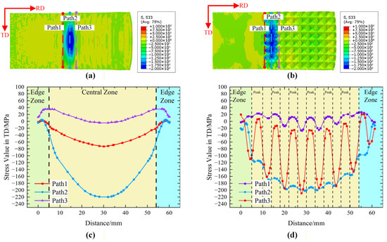
Figure 4.
The TD stress distribution in the TD path in the rolling deformation zone. (a) Stress contour distribution for the FR process, (b) stress contour distribution for the LSDR process, (c) stress curves for the FR process, (d) stress curves for the LSDR process.
The ND stress along the TD path is also predominantly compressive, and its magnitude increases toward the center of the rolling deformation zone, as shown in Figure 5a,b. In the FR process, as illustrated in Figure 5a,c, the magnitude of stress decreases rapidly from the center to the edges. The stress curves along both Path1 and Path2 exhibit a semi-circular shape. For Path1, the stress decreases from −58 MPa at the edge to −123 MPa at the center. For Path2, the stress drops sharply from −48 MPa at the edge to −255 MPa at the center. This indicates a significant variation in stress along the width of the plate. Due to elastic recovery and residual stresses in the plate after rolling, the stress along the post-rolling Path3 remains relatively low, fluctuating near 0 MPa. Under the LSDR process, as shown in Figure 5b,d, due to the unique shape of the rolls, the metal at the peaks of the corrugations is rolled first, while the metal at the troughs remains unrolled. This results in intense periodic fluctuations along Path1. As Path1 progresses from the edge toward the center, the stress decreases from −129.7 MPa to −225 MPa, whereas regions not yet subjected to roll pressure still register 0 MPa, providing sufficient deformation space for the initial deformation of the plate. Path2 is located at the center of the rolling deformation zone, where the entire plate surface is subjected to high compressive stress. However, due to the special structure of the corrugated roll surface, the stress exhibits distinct periodic fluctuations. Along Path2, the stress decreases from −53.7 MPa at the edge to −223.4 MPa in stages, with the maximum compressive stress significantly lower than that observed in the FR process. In the LSDR process, the variation in compressive stress on the plate aligns with the surface structure of the rolls. The unique configuration of the upper roll surface applies a strongly heterogeneous rolling force to the hard-to-deform magnesium alloy plate. At the peak positions of the corrugations, the stress applied in the ND is maximized, inducing intense localized plastic deformation. However, since the roll surface follows a sinusoidal variation within each grid cycle, the metal can flow appropriately within the grid, which moderately reduces the maximum rolling pressure. The compressive stress in the ND direction is more uniformly distributed across the entire plate surface, significantly reducing stress differences along different paths. This uniformity promotes consistent mechanical properties across the plate. Under the same rolling reduction rate, localized large plastic deformation occurs, refining the grain structure and enhancing the mechanical properties of the material.
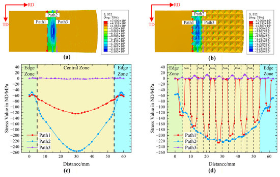
Figure 5.
The ND stress distribution in the TD path in the rolling deformation zone. (a) Stress contour distribution for the FR process, (b) stress contour distribution for the LSDR process, (c) stress curves for the FR process, (d) stress curves for the LSDR process.
3.2. Analysis of Temperature Distribution in the Deformation Zone
The relatively low thermal conductivity and volumetric heat capacity of magnesium alloy AZ31B make it more susceptible to cooling effects when in contact with cold rolls. This increases temperature non-uniformity during the rolling process [29]. In magnesium alloy rolling, uneven temperature distribution leads to non-uniform deformation of the metal plate, thereby promoting the propagation of edge cracks. Based on research findings regarding the influence of rolling temperature on edge cracking and microstructure of AZ31B magnesium alloy plates [8], it is observed that when rolled at 350 °C or below, shear bands consistently appear in the microstructure at the edges along the RD of AZ31B magnesium plates. As the temperature increases, these shear bands gradually disappear, giving way to a significant formation of twin structures. When the temperature rises to the recrystallization range (380–450 °C), complete recrystallization occurs, accompanied by grain growth. Therefore, in regions above the recrystallization temperature, grains are fully refined during the rolling process. In contrast, lower-temperature regions exhibit a high density of shear bands, dominated by twin deformation. The aggregation of shear bands promotes the clustering and propagation of cracks along the plate width, while the accumulation of twin plates also leads to microstructural inhomogeneity, facilitating crack extension along twin boundaries.
Figure 6 shows the temperature distribution and variation along the RD before and after the rolling deformation zone on the plate surface. In the FR process, a significant temperature gradient is observed in the magnesium alloy plate during rolling, as illustrated in Figure 6a,c. The temperature drop along the RD is similar for all three paths, decreasing from an initial 398.5 °C to a final stable temperature of 302.5 °C, indicating substantial heat loss during rolling. The range where the temperature exceeds the recrystallization temperature of 380 °C is only about 2 mm, while the range above 350 °C extends to approximately 7 mm. The low rolling temperature and rapid cooling in this region promote the formation of numerous shear bands. In the LSDR process, although the rate of temperature drop along the three paths is similar, the overall temperature reduction is significantly lower compared to the FR process. The temperature decreases from 399 °C upon entering the roll gap to 325 °C. Corrugated rolling effectively preserves the temperature of the plate. The localized severe deformation imparts greater strain to the material [30], while the unique structure of the corrugated roller provides additional frictional stress and shear effects [31], thereby generating extra heat. This is reflected by a noticeable step at the 16 mm position, indicating a delayed temperature decline trend, which creates a more favorable thermal environment for the plastic deformation of the plate. During rolling, the zone above the recrystallization temperature of 380 °C extends to 5.28 mm, and the zone above 350 °C reaches 12.3 mm. This results in a larger rolling temperature range that is less prone to edge cracking compared to the FR process. In contrast to the FR process, LSDR offers better thermal retention, keeping most of the rolling zone above temperatures conducive to edge crack suppression. This effectively mitigates the risk of edge cracking caused by rapid temperature drops.

Figure 6.
The temperature distribution in the RD path in the rolling deformation zone. (a) Temperature contour distribution for the FR process, (b) temperature contour distribution for the LSDR process, (c) temperature curves for the FR process, (d) temperature curves for the LSDR process.
Figure 7 illustrates the temperature distribution and variation along the TD before and after the rolling deformation zone on the plate surface. For the FR process, as shown in Figure 7c,d, upon entering the roll gap, the temperatures at the edge and center of Path1 are 379.6 °C and 386.5 °C, respectively, resulting in a temperature difference of 6.9 °C. Path2 exhibits an M-shaped profile with more complex temperature variations, showing a maximum temperature difference of 10 °C between the edge and center. Path3 is located in the zone where rolling deformation concludes, and the temperature gradually evens out, with a maximum temperature difference of 3 °C. In the FR process, the deformation zone exhibits a distinct and continuous temperature difference between the edge and center of the plate surface. This temperature variation between the center and edge regions can lead to differences in elongation, resulting in additional tensile stresses [9]. For the LSDR process, as shown in Figure 7c,d, Path1 exhibits periodic fluctuations. The peaks of the corrugated roll contact the metal plate first, resulting in a significant surface temperature drop due to heat exchange. The temperature difference between the peaks and valleys reaches 10 °C. However, the temperatures at the center and edge of the plate remain consistent, with the peaks and valleys measuring 398 °C and 388 °C, respectively. Path2 also exhibits periodic fluctuations, but the temperature variations at the peaks and valleys of the roll are opposite to those observed in Path1. At the roll peaks, severe deformation generates additional heat, raising the temperature to 365 °C. In contrast, at the roll valleys, deformation is minimal and insufficient to offset the heat loss from thermal exchange, resulting in a temperature of 358 °C. The temperature difference between peaks and valleys is reduced to 7 °C. Similarly, the temperatures at the peaks and valleys at the plate edges align with those at the center. The LSDR process effectively confines temperature variations within the individual lattice. The periodic fluctuations along Path3 are less pronounced, with a temperature difference of only 5 °C between peaks and valleys. The temperatures corresponding to the roll peaks and valleys are 327 °C and 322 °C, respectively. It is noted that the plate temperature at a distance of 61 mm is relatively low, approximately 312 °C. This is because the edge at this location coincides with the roll surface valley, where the deformation is limited, resulting in weaker deformation-induced heat generation, while stronger convective heat transfer further reduces the temperature. However, at this stage the material has already exited the rolls, and thus this temperature reduction does not affect the deformation process. The LSDR process effectively reduces the temperature difference between the edge and the center of the plate. In particular, along Path2, where rolling deformation is most severe, the temperature difference between the edge and the center is minimal. This unique rolling mode ensures a more uniform temperature distribution on the plate surface during rolling, thereby partially eliminating the conditions for crack initiation caused by temperature inhomogeneity. Additionally, the special surface structure of the rolls increases friction and contact area between the rolls and the magnesium plate. Simultaneously, the intense localized deformation during the severe rolling process generates additional rolling heat. Compared with the FR process, the LSDR process provides more favorable thermal conditions for eliminating shear bands and promoting recrystallization of twins in the edge microstructure of the magnesium plate.

Figure 7.
The temperature distribution in the TD path in the rolling deformation zone. (a) Temperature contour distribution for the FR process, (b) temperature contour distribution for the LSDR process, (c) temperature curves for the FR process, (d) temperature curves for the LSDR process.
3.3. Evaluation and Analysis of Rolling Crack Damage
According to the application conditions of the Cockcroft and Latham fracture criterion, for a given material under specific temperature and strain rate conditions, fracture occurs when the maximum tensile stress–strain reaches the material’s critical damage value [32]—this aligns with the fundamental mechanism of edge cracking in magnesium alloy rolling. The Cockcroft and Latham criterion is expressed in Equation (1) [32]:
In Equation (1), denotes the material damage variable. When reaches the critical damage value , fracture occurs. The critical damage value is influenced by factors such as temperature and deformation rate. represents the equivalent plastic strain at fracture, is the equivalent stress, is the increment of equivalent strain, and is the maximum principal stress experienced by the material.
Based on Gleeble isothermal compression simulation tests, under the same strain rate, the critical strain increases with rising temperature; at the same temperature, the critical strain decreases as the strain rate increases. This indicates that the critical fracture strain during hot working of magnesium alloys exhibits a specific correlation with both strain rate and temperature [29]. Based on the Zener-Hollomon expression derived from Gleeble experiments [33], the relationship between the critical damage parameter for magnesium alloy hot working and the parameter is established. The parameter is a key indicator for assessing the influence of different deformation temperatures and strain rates on material hot deformation [34,35]. It characterizes the varying deformation mechanisms during the material’s deformation process, reflecting the combined effects of deformation temperature and strain rate on fracture. The expression for the parameter is as follows:
In the equation, represents the deformation activation energy (J/mol) of the magnesium alloy, is the gas constant (8.314 J/(mol·K)), and is the temperature (°C). The relationship between the parameter and the critical damage value for AZ31B magnesium alloy under different strain rates and rolling temperatures is given as follows [36]:
In this experiment, the rolling temperature is 400 °C, the initial thickness of the magnesium alloy plate is 5 mm, the final thickness after rolling is 2.75 mm, and the rolling speed is 1.5 mm/s. Based on calculations, the critical cracking value is determined to be 0.43. By comparing the actual damage value along the plate width with , the following scenarios apply: if , no cracks form; if , crack initiation occurs, and if , cracks begin to propagate, leading to edge cracking. By comparing the calculated values, it is possible to predict whether edge cracking will occur during magnesium alloy rolling and assess the extent of crack propagation.
The damage data along the rolling direction (RD) on the surface and side edge of the plate under the FR process were selected, as shown in Figure 8c. The distribution curve of damage values is illustrated in Figure 8a, while the corresponding experimentally observed plate damage is presented in Figure 8b. Based on the Path1, the peak damage values in the central region of the plate exceed the critical damage value of 0.43, indicating severe edge cracking along the plate edge, consistent with the experimental results in Figure 8b. The minimum damage value is 0.2, suggesting that the edge cracks are gradually propagating into the surrounding area. Meanwhile, the peak damage values along Path2 are even higher, also exceeding the critical damage value, with a maximum peak of 0.7 and a minimum of 0.19. This indicates that the side edge is highly prone to the formation of extensive and destructive cracks. During rolling, the metal in the central region of the contact zone between the plate and the rolls flows more rapidly, whereas the metal near the edges flows more slowly, resulting in non-uniform metal flow before and after the deformation zone. In addition, the rapid temperature drop reduces the plastic deformability of the material, leading to the development of relatively large additional tensile stresses at the plate edges. Consequently, the fracture damage value at the edges becomes higher, which promotes the initiation and propagation of edge cracks, ultimately resulting in edge cracking. Both simulation and experimental results indicate that, under FR process conditions, cracks are highly prone to initiate and propagate in the edge and side regions of the plate. The damage values at the mid-length edge and side regions of the rolled plate exhibit a distribution pattern consistent with the observed edge-crack distribution after rolling, with crack depths extending more than 6 mm along the TD.
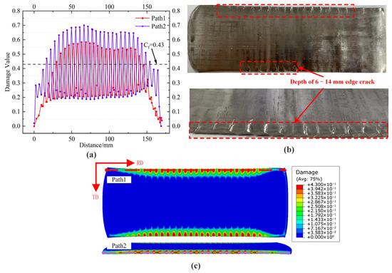
Figure 8.
Damage distribution and edge cracking in the FR process. (a) Damage value distribution curve, (b) edge crack topography, (c) damage distribution contour.
In the LSDR process, due to the asymmetry of the plate during rolling, four paths were selected to study the damage values—two on the edge of the surface and two on the side edge of the plate, as shown in Figure 9c. Path1 is located on the side with an incomplete dot-matrix pattern, where relatively high local damage values are observed, reaching up to 0.64, indicating a high tendency for damage initiation. However, the damage is mainly concentrated in the roll surface peak regions and confined to a limited area, while the damage in the other valley regions is nearly zero, effectively suppressing further damage propagation. For Path2, the damage values along the entire path remain below the critical damage value of 0.43. In this region, the plate edge exhibits a complete corrugated grid structure, such that the edge is located in the roll surface valley and can be effectively supported and constrained by the roll surface, resulting in very low damage values that do not satisfy the conditions for crack initiation. Compared with the FR process, although surface cracks may still occur on plates produced by the LSDR process, the crack-affected regions are significantly restricted, and crack propagation is strongly inhibited. For the side edge paths, namely Paths 3 and 4, the peak damage values in the central region of the plate just exceed 0.43, whereas the minimum damage value in the deformation center region is as low as 0.16. These damage levels are substantially lower than those on the plate side surfaces obtained by the FR process, indicating that the likelihood of edge crack initiation and the resulting crack size are much smaller for plates processed by LSDR.
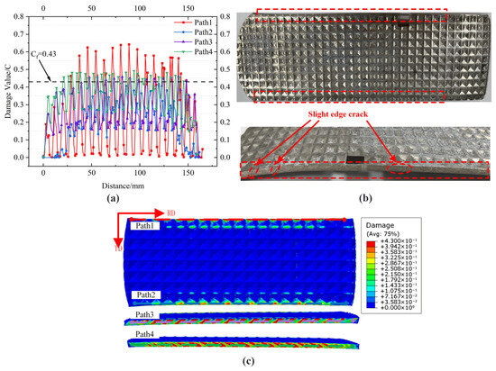
Figure 9.
Damage distribution and edge cracking in the LSDR process. (a) Damage value distribution curve, (b) edge crack topography, (c) damage distribution contour.
In summary, by comparing the damage contour maps of the magnesium alloy edges under the two rolling processes based on the Cockcroft–Latham fracture criterion, as shown in Figure 8c and Figure 9c, it can be observed that the FR process exhibits a large surface damage region, with extensive areas exceeding the critical damage value. As rolling proceeds, cracks are prone to initiate and propagate toward the plate interior. Although regions with damage values higher than the critical value are also observed on the plate surface processed by the LSDR process, most of the overall damage values only slightly exceed the critical level. Moreover, damage accumulation is confined within the severe deformation lattice, with no evident tendency to extend toward the plate center. Furthermore, as is evident from Figure 8a and Figure 9a, the cumulative damage values under the FR process are generally higher than those under the LSDR process. This indicates that the FR process is more prone to meeting the conditions for crack initiation and propagation compared to the LSDR process. The above observations indicate that the surface structure introduced by the LSDR process effectively restricts crack initiation and propagation. Its capability to suppress edge cracking is markedly superior to that of the FR process, further confirming that the LSDR process provides a significant inhibitory effect on edge damage during the rolling of magnesium alloy plates.
3.4. Microstructural Characterization Analysis
The microstructure near cracks under the FR process is shown in Figure 10. As illustrated in Figure 10a, the magnesium plate produced by the FR process exhibits distinct edge cracks. These cracks propagate along the TD toward the center of the plate and are distributed periodically along the edge. The cracks penetrate through the thickness of the plate in the ND at the edge regions. Microstructural observations reveal that, in the vicinity of edge cracks after rolling, initially formed microcracks oriented at approximately 45° to the RD can be observed, accompanied by shear bands, as shown in Figure 10b–d. Shear bands are typical rolling-induced microstructural features, contributing to a certain degree of microstructural inhomogeneity [37]. The microcracks preferentially initiate and propagate along the shear band direction [38], and with further edge deformation, they eventually evolve into the macroscopic cracks observed. Near the shear bands, a chain-like distribution of fine grains can be observed, formed through twin-induced dynamic recrystallization. In contrast, grains in other regions are coarse, with uneven grain sizes and a high density of twins. The accumulation of twin lamella also contributes to microstructural inhomogeneity, promoting crack propagation along twin boundaries [39]. The stress field generated during the FR process causes twins to straighten and thin. The abundance of thin twin boundaries leads to stress concentration at the plate edges, forming shear bands and microcracks, which ultimately develop into through-thickness edge cracks during rolling.
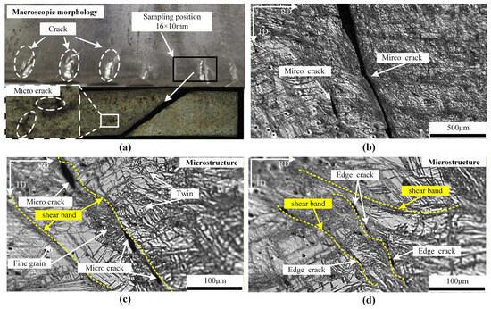
Figure 10.
Macroscopic morphology and microstructure of the plate edge under the FR process. (a) Macroscopic morphology, (b–d) microstructure.
The morphology and microstructure of the plate edge during the LSDR process are shown in Figure 11. Figure 11a displays the macroscopic morphology of the plate edge, which consists of a periodically patterned lattice-like structure. Although a few cracks are present, no significant or extensive edge cracks are observed. Microstructural observations show that, similar to the FR process, a large number of grain-boundary shear bands are also present in the edge microstructure of plates produced by the LSDR process, as shown in Figure 11b–d. These shear bands are primarily oriented toward the RD, and abundant fine-grained bands are also present between them. Compared to the coarse grains in other regions, the grains near these shear bands are finer and more uniform. This phenomenon can be attributed to the continuous wavy structure of the roll surface, which intensifies internal deformation in the plate during rolling, enhances atomic mobility, promotes dislocation movement, and provides additional energy for dynamic recrystallization. It also generates sufficient interfacial curvature driving force to facilitate nucleation and diffusion migration at grain boundaries [40]. It is noteworthy that, compared to the FR process, the number of twins in the microstructure of this region has increased. The substantial formation of twins absorbs energy required for crack propagation, thereby suppressing the expansion of edge cracks [17]. When twins accumulate, they can induce dynamic recrystallization. The energy consumed during twin nucleation or recrystallization grain nucleation renders cracks unable to propagate further due to energy insufficiency, leading to the formation of high-density twins or chain-like fine grains at the tips of edge cracks. Additionally, no twin lamella is observed around the shear bands. Instead, fine-grained regions intertwine with dislocation tangles induced by twins. The accumulation of dislocations inhibits further crack propagation and results in the termination of crack tips with high-density dislocations.
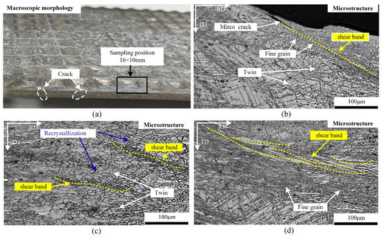
Figure 11.
Macroscopic morphology and microstructure of the plate edge under the LSDR process. (a) Macroscopic morphology, (b–d) microstructure.
4. Conclusions
(1) Under a preheating temperature of 400 °C with a holding time of 30 min and a reduction ratio of 45%, the conventional FR process exhibits significant differences in stress distributions along the RD, TD, and ND directions. During rolling, the plate edges experience relatively high tensile stresses, making the edge metal more prone to crack initiation. The application of the LSDR process significantly suppresses edge cracking during the rolling of magnesium alloy plates. This is attributed to the lattice-distributed severe deformation zones, which divide the metal plate into numerous small deformation regions during the forming process. This effectively disperses the stress distribution in all three directions, particularly confining the edge metal material within limited deformation zones. The maximum stress along the RD at the edges is reduced to 61.1 MPa, effectively decreasing the maximum tensile stress in these regions. Within a certain rolling interval, the stress state transitions to compressive stress, which suppresses the plastic deformation induced by tensile stress at the plate edges. Consequently, the mechanical conditions for edge cracking are effectively mitigated.
(2) Under a rolling reduction rate of 45%, the damage values at the edges of the plate produced by the FR are significantly higher than those from the LSDR process, exceeding the critical fracture threshold. Based on calculations using the Cockcroft and Latham fracture criterion, the damage values at the edges of the magnesium alloy plate under the FR process largely exceed the material’s critical fracture value of 0.43, exhibiting a continuous propagation trend. In contrast, although the damage values at the edges of the plate processed by LSDR also exceed the critical fracture threshold, the unique structure of the corrugated roll provides a favorable stress state environment for the plate surface. As a result, the overall damage values are lower than those in the FR process, and the trend of damage propagation is confined within the grid domains of the corrugated roll. It has also been verified that the LSDR process compensates for temperature drops at the edges of the magnesium plate. This process reduces the temperature difference between the edges and the center of the plate, thereby mitigating edge cracking caused by temperature variations.
(3) After the FR process, the edge regions of the magnesium alloy plate contain a high density of shear bands. These shear bands, combined with twin lamellae within the fine-grained regions, lead to stress concentration at the plate edges. As a result, cracks propagate along twin interfaces, initiating the formation of edge cracks. In comparison, after the LSDR process, the edge regions of the plate primarily develop fine-grained shear bands along the RD, accompanied by the formation of a large number of twins. The generation of twins consumes the energy required for edge crack propagation. Under recrystallization temperatures, the accumulation of twins further induces dynamic recrystallization, consuming additional energy and thereby suppressing the initiation and expansion of edge cracks. Meanwhile, the entanglement and accumulation of dislocations generated in the fine-grained regions and twin lamellae result in the crack tip terminating at a high dislocation density, thereby inhibiting further crack propagation.
In this study, a corrugated roll was designed based on the dot-matrix severe deformation principle. The roll features a regular wave-like surface profile with peaks and valleys, which can improve the stress and temperature distribution experienced by the plate during rolling, enhance microstructural and grain refinement, and thereby suppress edge cracking in rolled magnesium alloy plates to a certain extent.
Author Contributions
Conceptualization, G.F. and K.H.; methodology, G.F.; software, Z.L.; validation, Z.L.; formal analysis, Z.L. and K.H.; investigation, Z.L. and K.H.; resources, G.F.; data curation, Z.L.; writing—original draft preparation, Z.L. and K.H.; writing—review and editing, G.F.; visualization, Z.L.; supervision, G.F.; project administration, G.F.; funding acquisition, G.F. All authors have read and agreed to the published version of the manuscript.
Funding
This research was funded by the National Natural Science Foundation of China, grant number 52475392, 52074190; the Fundamental Research Program of Shanxi Province, grant number 202403021211208; the Research Project Supported by Shanxi Scholarship Council of China, grant number 2023-043; the Fund Program for the Scientific Activities of Selected Returned Overseas Professionals in Shanxi Province, grant number 20220007.
Data Availability Statement
The original contributions presented in this study are included in the article. Further inquiries can be directed to the corresponding author.
Conflicts of Interest
Author Kai Huang was employed by the company Avic Shaanxi Aircraft Industry Corporation Ltd. The remaining authors declare that the research was conducted in the absence of any commercial or financial relationships that could be construed as a potential conflict of interest.
Abbreviations
The following abbreviations are used in this manuscript:
| FR | Flat rolling |
| LSDR | Lattice severe deformation rolling |
| RD | Rolling direction |
| TD | Transverse direction |
| ND | Normal direction |
References
- Luo, Q.; Li, J.; Li, B.; Liu, B.; Shao, H.; Li, Q. Kinetics in Mg-based hydrogen storage materials: Enhancement and mechanism. J. Magnes. Alloys 2019, 7, 58–71. [Google Scholar] [CrossRef]
- Zhou, Y.; Fu, P.; Peng, L.; Wang, D.; Wang, Y.; Hu, B.; Liu, M.; Sachdev, A.K.; Ding, W. Precipitation modification in cast Mg–1Nd–1Ce–Zr alloy by Zn addition. J. Magnes. Alloys 2019, 7, 113–123. [Google Scholar] [CrossRef]
- Zheng, T.; Hu, Y.; Pan, F.; Zhang, Y.; Tang, A. Fabrication of corrosion-resistant superhydrophobic coating on magnesium alloy by one-step electrodeposition method. J. Magnes. Alloys 2019, 7, 193–202. [Google Scholar] [CrossRef]
- Zhang, Z.; Zhang, Y.; Zhang, H.; Pan, A.; Liu, J. Research on die casting process of magnesium alloy motorcycle wheel based on new engineering construction. J. Phys. Conf. Ser. 2019, 1302, 042024. [Google Scholar] [CrossRef]
- Xu, S.; Jia, W.; Song, Z. Effects of electromagnetic field on physical behaviors during low-frequency electromagnetic casting of Mg alloy AZ31. Mater. Res. Express 2019, 6, 066569. [Google Scholar] [CrossRef]
- Li, Y.; Yang, J.; Wang, H. Effect of Gd on microstructure and fracture behavior of AZ91 magnesium alloy. IOP Conf. Ser. Mater. Sci. Eng. 2018, 381, 012177. [Google Scholar] [CrossRef]
- Li, S.; Yang, X.; Hou, J.; Du, W. A review on thermal conductivity of magnesium and its alloys. J. Magnes. Alloys 2020, 8, 78–90. [Google Scholar] [CrossRef]
- Thirumurugan, M.; Kumaran, S.; Suwas, S.; Rao, T.S. Effect of rolling temperature and reduction in thickness on microstructure and mechanical properties of ZM21 magnesium alloy and its subsequent annealing treatment. Mater. Sci. Eng. A 2011, 528, 8460–8468. [Google Scholar] [CrossRef]
- Li, X.; Zhu, Y.; Li, H.; Niu, Y.; Yang, C. A new method of edge crack suppression in the rolling process of magnesium alloy sheet and study on the method of cathodic protection. Adv. Mater. Sci. Eng. 2020, 2020, 3169517. [Google Scholar] [CrossRef]
- Zhi, C.; Ma, L.; Huang, Q.; Huang, Z.; Lin, J. Improvement of magnesium alloy edge cracks by multi-cross rolling. J. Mater. Process. Technol. 2018, 255, 333–339. [Google Scholar] [CrossRef]
- Del Valle, J.; Pérez-Prado, M.T.; Ruano, O.A. Texture evolution during large-strain hot rolling of the Mg AZ61 alloy. Mater. Sci. Eng. A 2003, 355, 68–78. [Google Scholar] [CrossRef]
- Ding, Y.; Le, Q.; Zhang, Z.; Cui, J. Effect of rolling speed on microstructure and mechanical properties of as-cast AZ31B alloy under different reduction schedules. J. Mater. Process. Technol. 2016, 233, 161–173. [Google Scholar] [CrossRef]
- Liu, F.; Liu, X.; Zhu, B.; Yang, H.; Xiao, G.; Hu, M. Influence of microstructure and mechanical properties on formability in high strain rate rolled AZ31 magnesium alloy sheets. Met. Mater. Int. 2022, 28, 1361–1371. [Google Scholar] [CrossRef]
- Utsunomiya, H.; Sakai, T.; Minamiguchi, S.; Koh, H. High-speed heavy rolling of magnesium alloy sheets. Magnes. Technol. 2006, 2006, 201–204. [Google Scholar]
- Hamada, G.; Sakai, T.; Utsunomiya, H. Effect of rolling speed on deformability and microstructure in rolling of AZ31B magnesium alloy. Adv. Mater. Res. 2010, 89, 227–231. [Google Scholar] [CrossRef]
- Koh, H.; Sakai, T.; Utsunomiya, H.; Minamiguchi, S. Deformation and texture evolution during high-speed rolling of AZ31 magnesium sheets. Mater. Trans. 2007, 48, 2023–2027. [Google Scholar] [CrossRef]
- Zhu, S.; Yan, H.; Chen, J.; Wu, Y.; Liu, J.; Tian, J. Effect of twinning and dynamic recrystallization on the high strain rate rolling process. Scr. Mater. 2010, 63, 985–988. [Google Scholar] [CrossRef]
- Zhu, S.; Yan, H.; Chen, J.; Wu, Y.; Su, B.; Du, Y.; Liao, X. Feasibility of high strain-rate rolling of a magnesium alloy across a wide temperature range. Scr. Mater. 2012, 67, 404–407. [Google Scholar] [CrossRef]
- Jiang, J.; Wu, J.; Ni, S.; Yan, H.; Song, M. Improving the mechanical properties of a ZM61 magnesium alloy by pre-rolling and high strain rate rolling. Mater. Sci. Eng. A 2018, 712, 478–484. [Google Scholar] [CrossRef]
- Jia, W.; Ning, F.; Ding, Y.; Le, Q.; Tang, Y.; Cui, J. Role of pre-width reduction in deformation behavior of AZ31B alloy during break-down rolling and finish rolling. Mater. Sci. Eng. A 2018, 720, 11–23. [Google Scholar] [CrossRef]
- Sun, J.; Zhang, J.; Liu, D.; Huang, H.; Yan, M. Inhibition behavior of edge cracking in the AZ31B magnesium alloy cold rolling process with pulsed electric current. Metals 2023, 13, 274. [Google Scholar] [CrossRef]
- Huang, Z.; Qi, C.; Zou, J.; Lai, H.; Guo, H.; Wang, J. Edge crack damage analysis of AZ31 magnesium alloy hot-rolled plate improved by vertical roll pre-rolling. J. Magnes. Alloys 2023, 11, 2151–2164. [Google Scholar] [CrossRef]
- Wang, H.; Yu, Z.; Zhang, L.; Liu, C.; Zha, M.; Wang, C.; Jiang, Q. Achieving high strength and high ductility in magnesium alloy using hard-plate rolling (HPR) process. Sci. Rep. 2015, 5, 17100. [Google Scholar] [CrossRef] [PubMed]
- Guo, F.; Zhang, D.; Yang, X.; Jiang, L.; Chai, S.; Pan, F. Influence of rolling speed on microstructure and mechanical properties of AZ31 Mg alloy rolled by large strain hot rolling. Mater. Sci. Eng. A 2014, 607, 383–389. [Google Scholar] [CrossRef]
- Hao, P.; Liu, Y.; Wang, Z.; Wang, T.; He, D.; Huang, Q.; Wang, Z. Analysis of force and deformation parameters in corrugated clad rolling. Int. J. Mech. Sci. 2023, 243, 108042. [Google Scholar] [CrossRef]
- Giorjao, R.A.R.; Monlevade, E.F.d.; Avila, J.; Tschiptschin, A.P. Numerical Modeling of Flow Stress and Grain Evolution of an Mg AZ31B Alloy Based on Hot Compression Tests. J. Braz. Soc. Mech. Sci. Eng. 2020, 42, 57. [Google Scholar] [CrossRef]
- Li, W.; Dai, H.; Yan, Z.; Liu, X.; Xu, Y. Impact of Zener-Hollomon parameter on hot deformation behavior of AZ61 magnesium alloy. J. Yanshan Univ. 2021, 45, 328–334, 342. [Google Scholar] [CrossRef]
- Bayoumi, L.S. Edge stresses in wide strip hot rolling. Int. J. Mech. Sci. 1997, 39, 397–408. [Google Scholar] [CrossRef]
- Dong, J.; Zhang, D.; Dong, Y.; Pan, F.; Chai, S. Critical damage value of AZ31B magnesium alloy with different temperatures and strain rates. Rare Met. 2021, 40, 137–142. [Google Scholar] [CrossRef]
- Han, G.; Li, H.; Zhang, J.; Kong, N.; Liu, Y.; You, X.; Xie, Y.; Shang, F. Prediction and Analysis of Rolling Process Temperature Field for Silicon Steel in Tandem Cold Rolling. Int. J. Adv. Manuf. Technol. 2021, 115, 1637–1655. [Google Scholar] [CrossRef]
- Wang, T.; Liu, W.; Liu, Y.; Wang, Z.; Ignatov, A.; Huang, Q. Formation Mechanism of Dynamic Multi-Neutral Points and Cross Shear Zones in Corrugated Rolling of Cu/Al Laminated Composite. J. Mater. Process. Technol. 2021, 295, 117157. [Google Scholar] [CrossRef]
- Cockcroft, M. Ductility and workability of metals. J. Met. 1968, 96, 2444. [Google Scholar]
- Wang, Y.; Li, J.; Xin, Y.; Li, C.; Cheng, Y.; Chen, X.; Rashad, M.; Liu, B.; Liu, Y. Effect of Zener–Hollomon parameter on hot deformation behavior of CoCrFeMnNiC0. 5 high entropy alloy. Mater. Sci. Eng. A 2019, 768, 138483. [Google Scholar] [CrossRef]
- Jia, W.; Ma, L.; Le, Q.; Zhi, C.; Liu, P. Deformation and fracture behaviors of AZ31B Mg alloy at elevated temperature under uniaxial compression. J. Alloys Compd. 2019, 783, 863–876. [Google Scholar] [CrossRef]
- Wu, B.; Li, J.; Liu, L.; Chen, X.; Tan, J.; Song, J.; Rashad, M.; Pan, F. Effect of Zener–Hollomon parameter on high-temperature deformation behaviors of Mg–6Zn–1.5 Y–0.5 Ce–0.4 Zr alloy. Acta Metall. Sin. 2021, 34, 606–616. [Google Scholar] [CrossRef]
- Ning, F.; Jia, W.; Hou, J.; Chen, X.; Le, Q. Construction of edge cracks pre-criterion model based on hot rolling experiment and simulation of AZ31 magnesium alloy. Mater. Res. Express 2018, 5, 056528. [Google Scholar] [CrossRef]
- Üçel, İ.B.; Kapan, E.; Türkoğlu, O.; Aydıner, C.C. In situ investigation of strain heterogeneity and microstructural shear bands in rolled Magnesium AZ31. Int. J. Plast. 2019, 118, 233–251. [Google Scholar] [CrossRef]
- Al-Samman, T.; Gottstein, G. Room temperature formability of a magnesium AZ31 alloy: Examining the role of texture on the deformation mechanisms. Mater. Sci. Eng. A 2008, 488, 406–414. [Google Scholar] [CrossRef]
- Grilli, N.; Cocks, A.C.; Tarleton, E. Modelling the nucleation and propagation of cracks at twin boundaries. Int. J. Fract. 2022, 233, 17–38. [Google Scholar] [CrossRef]
- Wang, W.; Miao, Q.; Chen, X.; Yu, Y.; Zhang, W.; Chen, W.; Wang, E. Critical rolling process parameters for dynamic recrystallization behavior of AZ31 magnesium alloy sheets. Materials 2018, 11, 2019. [Google Scholar] [CrossRef]


Disclaimer/Publisher’s Note: The statements, opinions and data contained in all publications are solely those of the individual author(s) and contributor(s) and not of MDPI and/or the editor(s). MDPI and/or the editor(s) disclaim responsibility for any injury to people or property resulting from any ideas, methods, instructions or products referred to in the content. |
© 2026 by the authors. Licensee MDPI, Basel, Switzerland. This article is an open access article distributed under the terms and conditions of the Creative Commons Attribution (CC BY) license.