Abstract
The use of weld bond (WB) joints in automotive manufacturing is gaining popularity for joining similar and dissimilar materials. This study investigated the effect of Sikaflex-252 (Sika Australia Pty Ltd, Perth, Australia) adhesive in DP600 similar steel joints and DP600 and AISI 316 stainless steel dissimilar steel joints. An increase in welding current from 7 kA to 10 kA increased the weld diameter and tensile shear strength in the RSW joints and the WB joints. WB joints had bigger weld diameters of 5.39 mm and 4.84 mm, higher tensile shear strengths of 12.3 kN and 6.85 kN, and higher energy absorption before failure of 32.6 J and 24.6 J at 10 kA compared to joints at 7 kA for similar and dissimilar joints, respectively. The use of adhesive increased heat generation at 10 kA welding current, due to the increase in dynamic resistance. At 7 kA welding current, the adhesive could not produce sufficient heat for spot weld development. The use of adhesive narrowed the weldability lobe in dissimilar RSW and WB joints and showed changes in failure mode. In similar RSW joints and WB joints, weldability lobe changes were not observed, and RSW and WB joints had the same fracture mode for the same welding current. WB welds have reduced stress distribution across the weld nugget compared to RSW welds because of the bigger weld diameter of 5.39 mm and lesser sheet bending of 1.13 mm. WB joint failure comprises the adhesive failure at the start and later the spot weld failure, while RSW joint failure is purely due to spot weld failure.
1. Introduction
Automotive designers and manufacturers adopted Multi-Material Design (MMD) due to the stricter government regulations and increased demand for automotives that are lighter in weight with reduced fuel consumption, improved structural strength, and contribute to reduced carbon emissions. In the MMD, the automotive Body in White (BiW), as shown in Figure 1a, is made from a combination of materials [1]. Resistance Spot Welding (RSW) is the traditional joining method used in steel-based BiWs. There are, on average, around 5000 spot welds in the BiW [2]. During the RSW process, a high current flows through the metal sheets to be joined. The sheets, clamped between two water-cooled copper electrodes, are subjected to localized melting at the sheets’ interface, under the force exerted by the electrodes. A joint is created through the solidification of the volume of material in the melted area, forming a weld nugget or spot weld [3]. Figure 1b shows spot welds used for a BiW assembly. The minimum acceptable weld size ranges from 3 mm to 7.5 mm in diameter [4].

Figure 1.
(a) BiW with different combinations of materials and (b) Spot welds used in BiW assembly.
RSW faced challenges forming spot weld joints with MMD materials such as steel, aluminum, or steel–polymer-based composites. The vast difference in thermal conductivity between steel and aluminum or polymer-based composite [5], brittle intermetallic compounds (IMC) formation when joining aluminum and steel [5,6], as well as non-conductive properties of polymer and polymer-based composites [7] were the reasons for the difficulty in forming quality spot weld joints. RSW variants, such as the use of coaxial electrodes, interlayers, and inserts [6,8,9,10,11], successfully formed MMD spot weld joints. These methods, however, raised concerns about an increase in production cost, an increase in the weight of the automotive structure due to the addition of materials, and the potential corrosion within the intermediate layers [12,13]. Adhesive bonding is an important joining method used in MMD due to its ability to bond different materials, bond thin materials, and superior mechanical absorption properties [14]. Adhesive bonding requires surface cleaning and is affected by factors such as humidity, temperature, curing time, and adhesive type [15,16,17,18]. Adhesive-bonded joints have been reported to demonstrate improved stiffness, strength, and uniform load distribution compared to mechanically fastened joints or welded joints [19,20,21]. Weld bond (WB) is a joining method that combines the advantages of both the RSW and adhesive bonding [22]. WB and structural adhesives are widely used in vehicle lightweight BiW structures such as longitudinal rails, vertical pillars, reinforcement beams, sunroof frames, and horizontal closure panels (bonnets, roof, and trunk lids) [23,24,25].
Recent Research on Weld Bond (WB)
Weld bonding is a metal joining technology in which structural adhesives are applied to the faying surfaces of the metal sheets to be joined, cured for a recommended time, and subsequently spot welded. Figure 2 shows the WB process.
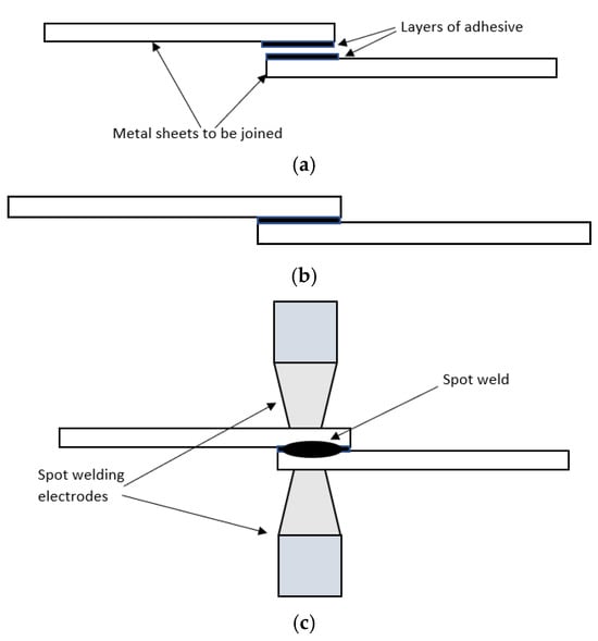
Figure 2.
(a) Metal sheets to be joined with adhesive layers at the faying surface, (b) sheets assembled to form a joint, and (c) spot weld formed at faying surfaces.
The study on WB joints of DP600 steels with Terostate 9220 and Loctite Terostat MS930 polymer adhesives reported that adhesive types and steel coating govern the achievable joint strength [26]. A stronger weld joint was observed for the WB joint between magnesium and steel with Terokal 5087-02P adhesive compared to RSW dissimilar joints of magnesium and steel [27]. The study showed that the adhesive affects microstructural changes in the fusion zone. WB joints with Betamate 1496 V epoxy-based adhesive showed that the tearing strength of adhesive-bonded joints can be improved with the reinforcement of spot welds to form a WB joint [28]. WB joints between aluminum alloy and epoxy adhesive Araldite 420 A/B improved the fatigue life in the WB joints [29].
The WB joints between aluminum alloy and epoxy adhesive CHS-EPODUR 619 showed that WB joints have double the load-carrying capacity compared to RSW joints, and the energy absorption before failure of WB joints is six times greater than the energy absorption capability of RSW joints [30]. WB joints between interstitial free (IF) steel and Syntho Subsea Epoxy adhesive showed higher energy absorption before failure compared to RSW joints and adhesive-bonded joints [31]. The difference in ductility between Sikaforce 7752, Araldite AV138, and Araldite 2015 showed that the most ductile Sikaforce 7752 improved the weld joint, and the most brittle Araldite AV138 showed the least improvement in WB joint strength [32]. The changes in loading angles affect the WB joint’s strength; with the strength of the WB joints similar to the strength of RSW joints at 0°, while the strength of the WB joints is higher than the RSW joints at 90° [33].
No work has been reported to date on the combination of two important steels in automotive manufacturing: the DP600 and AISI 316 stainless steel. This study provides insights into WB joints by studying the effect of adhesive in similar and dissimilar joints of DP600 and AISI 316 stainless steel. Notably, the combination of DP600 and stainless steel with Sikaflex adhesive has not been reported. The effect of the adhesive on similar and dissimilar steel joints will be critically analyzed to validate reports suggesting that WB joints enhance the stiffness, fatigue characteristics, and crashworthiness of automotive [17,34]. Additionally, the effect of adhesive on the stress distribution in WB joints will be examined through finite element analysis.
2. Materials and Methods
2.1. Materials for Experimentation
DP600 steel, manufactured by SSAB Vintrosa, Sweden, with a thickness of 1.4 mm was used in this study. DP600 is a heat-treated dual-phase steel featuring a ferrite and martensite microstructure for enhanced strength. Dual-phase steel features soft ferrite microstructures as a matrix containing martensite islands [35]. To analyse dissimilar steel joints, austenitic stainless steel AISI 316, manufactured by Vulcan Western Australia, Australia, with a thickness of 1 mm was used. Tensile test specimens were prepared according to AWS/ANSI D8.9-97 [36] standard with the steel cut into 95 mm × 30 mm strips and arranged as shown in Figure 3a. For the WB joints, the adhesive produced a 0.5 mm layer between the two specimens to be joined, as shown in Figure 3b. Welding specimens, mainly the weld area, were cleaned using a chemical solution for 10 s to remove any remaining contaminants. Table 1 shows the compositions, by weight%, of DP600 and AISI 316 stainless steels, and Table 2 shows the properties of DP600 and AISI 316 stainless steels. The adhesive used in this experiment is Sikaflex-252, a polyurethane adhesive manufactured by Sika Australia Pty Ltd, Western Australia, Australia. Table 2 also shows the properties of this adhesive [37]. As shown in Figure 4, Sikaflex-252 curing time depends on factors such as atmospheric temperature, relative humidity, and the thickness of the adhesive applied.

Figure 3.
(a) Spot weld specimen, (b) weld bond specimen with adhesive.

Table 1.
Compositions, by weight%, of DP600 and AISI 316 stainless steel (provided by suppliers).
Table 2.
Properties of DP600, AISI 316 stainless steel, and Sikaflex 252 adhesive (provided by material suppliers and adhesive datasheet).
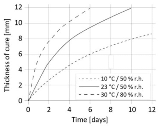
Figure 4.
Sikeflex-255 curing time and thickness. Reprinted from Ref. [37].
2.2. Machines and Instrumentations
The Tecna 25 kV, 50 Hz industrial pedestal spot welding machine(Tecna, Castel San Pietro Terme (BO) Italy) fitted with a Tecna microprocessor control unit for weld current and time input and control was used for this experimentation. The machine has a pneumatic electrode actuation system and was fitted with 6 mm tip diameter water-cooled copper electrodes. A calibrated current toroid was fitted to the machine’s lower arm for weld current monitoring. The weld specimens were subjected to tensile–shear tests and metallographic examination. The tensile–shear tests were conducted using a 50 kN tensile testing machine with a crosshead speed set at 5 mm/min. The specimens were gripped 45 mm into each jaw face before the tensile shear tests started. Tensile shear load and displacement curves were plotted during the tests. The metallographic specimens were sectioned across the center of the weld nugget and placed in an epoxy mount. Once the epoxy mounts set and fully cured, they were ground and polished using standard metallographic procedures. The purpose of the metallographic specimens was to measure spot weld nugget diameter. Nital (98% ethanol and 2% nitric acid) was used to etch the polished specimens and reveal the weld fusion zone (FZ). An Olympus BXSIM microscope with variable magnification was used to measure the FZ diameters, which represent the spot weld nugget diameters.
2.3. Welding Schedule and Joint Preparation
The experimentation studied the difference in weld strength between similar RSW steel joints (without adhesive between DP600 + DP600), similar WB joints (adhesive between DP600 + DP600), dissimilar RSW steel joints (without adhesive between DP600 + 316SS), and dissimilar WB joints (adhesive between DP600 + 316SS) as in Table 3.
Table 3.
Experimentation welding schedule.
The experimentation used a current range of 7 kA–10 kA. The squeeze time, weld time, hold time, and electrode force were fixed at 30 cycles (50 cycles = 1 s), 40 cycles, 35 cycles, and 2.8 kN, respectively. Three different currents were used for similar DP600 steel joints, and four different currents were used for dissimilar DP600 and AISI 316 stainless steel joints due to the availability of DP600 steel for the experimentation. The minimum and maximum currents were kept the same for all joints, as these currents were considered crucial for weld strength comparisons. The machine’s weldability lobe for DP600 + DP600 was between 6.5 kA to 11 kA, and for DP600 + 316SS was between 7 kA to 10 kA. The weldability lobe study for the similar and dissimilar joints was conducted following procedures in the ISO 18278-1 [38] standard. Three specimens were prepared for each welding schedule and joint type, and an additional two specimens were produced for 7 kA and 10 kA currents for metallographic examination; 58 specimens were prepared in this experiment. The WB joints were prepared by applying the adhesive to the overlap area of one specimen, following the manufacturer’s Product Design Specification (PDS). The adhesive was cured at an optimum period of four hours at an ambient temperature of 24 °C in an air-conditioned environment, before the specimens were spot-welded. The optimum hours were as recommended in Figure 4 and based on the trial-and-error method.
2.4. Finite Element Analysis (FEA) Models for Stress Analysis
The stress distribution across the weld nugget was analyzed using ANSYS Workbench 2024. The stress analyses were conducted for the RSW DP600 + DP600 and WB DP600 + DP600 weld joints at 10 kA welding current, to study the effect of adhesive on stress distribution across the weld diameter. Due to the symmetry of the specimen, the models were produced with only one-half of the specimen, as in Figure 5a,b. The weld diameters in the models are the diameters that were experimentally obtained. Based on the metallographic specimens, the models’ heat-affected zone (HAZ) thickness was assumed to be 10% of the nugget radius, i.e., 0.2 mm for RSW DP600 + DP600 and 0.3 mm for WB DP600 + DP600. The assumptions are closer to the HAZ width values of 0.3 mm and 0.4 mm used in [39] for the DP600 steel FEA model and the HAZ width value of 0.5 mm, experimentally obtained in [40] for galvanized DC51D steel.

Figure 5.
(a) RSW DP600 + DP600 FEA model, and (b) WB DP600+ DP600 FEA model.
The models were divided into three segments: the weld nugget (FZ), the HAZ, and the DP600 base metal. The hardness for each segment was adapted from Janardhan et al. [41]’s work. The DP600 base metal’s Young’s modulus, shear modulus, and Poisson’s ratio were taken as 210 GPa, 82 GPa, and 0.28, respectively [42,43]. The other segments’ Young’s modulus and shear modulus are assumed to be proportional to the respective hardness, and the Poisson’s ratio was maintained constant for all segments. Table 4 provides details on the materials properties used in the analysis. The SHELL181 element was used for the DP600 steels and spot welds, with finer meshes of 36,316 nodes and 17,844 elements for the weld nugget for accurate computation, while the adhesive for the WB model was modelled using cohesive zone elements. Denser meshes were generated where the stress concentration appears, such as in the nugget, HAZ, and around the boundaries. The boundary conditions applied to the models are as below:
Table 4.
Materials’ mechanical properties used in analysis.
3. Results and Discussion
3.1. Nugget Diameters and Shear Strengths of Spot Welded and Weld-Bonded Joints
The results showed that the average weld strength, in terms of tensile–shear force, increased as the welding current increased, as in Figure 6. Table 5 gives the average weld diameters at 7 kA and 10 kA welding current, which were measured through the metallographic examination. The weld diameters at 10 kA are closer to the recommended weld size [4].
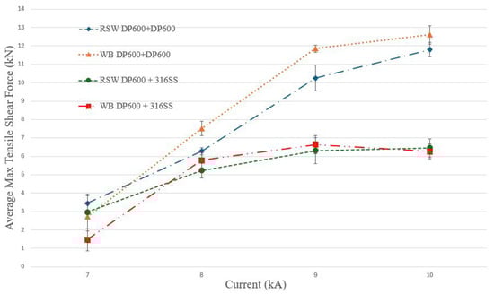
Figure 6.
Average maximum weld tensile strength vs. welding current.
Table 5.
Average minimum and maximum weld diameters for different joints, and 7 kA and 10 kA welding currents.
The observations in Figure 6 are due to the increase in weld nugget diameter at the sheets’ interface, as seen in Table 5. Figure 7 shows the measured weld diameter for RSW DP600 + DP600 at 10 kA using metallographic examination. The increase in welding current increased the heat to melt the metals at the sheet interface. The volume of metals melted and solidified to form a weld nugget increased with an increase in welding current, hence led to a bigger weld diameter [45,46,47]. Equation (1) shows the relationship between heat generation in spot welding and the welding current.
where Q—heat generation (J), I—welding current (A), R—dynamic resistance (Ω), and t—weld time (cycles). The equation showed that the welding current has a power of two, hence the most significant parameter for heat generation during welding.
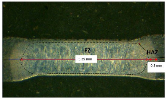
Figure 7.
Weld diameter for RSW DP600 + DP600 at 10 kA.
Figure 8 shows the spot weld formed for a dissimilar RSW joint at 10 kA current. The asymmetrical shape of the nugget was because the DP600 had higher thermal conductivity but lower resistance compared to AISI 316 stainless steel, as shown in Table 1. Heat flow caused the nugget to grow faster along the sheet thickness compared to along the sheet interface, causing the weld diameter on the DP600 side to be less compared to the weld diameter on the stainless-steel side. The higher heat concentration on the stainless steel side, due to higher electrical resistivity and lower thermal conductivity compared to DP600, formed a higher weld diameter on the stainless steel side [48].
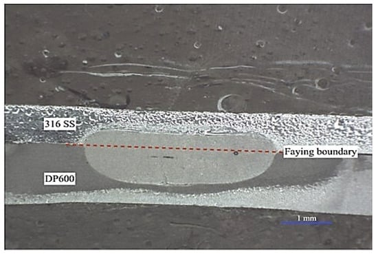
Figure 8.
Weld diameter for RSW DP600 + 316SS at 10 kA.
3.2. Energy Absorption Before Failure of Spot-Welded and Weld-Bonded Joints
The energy absorptions of the RSW joints and WB joints were obtained by measuring the area under the force–displacement curves, following AWS D8.1 M:2021 [4] standard, as illustrated in Figure 9. The energy absorbed before the failure of a joint is equal to the highlighted area and was calculated using Equation (2) [49,50]:
where Wmax—energy absorption, Pmax—the peak load, and Lmax—the elongation at the peak load.
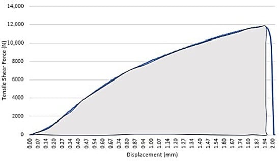
Figure 9.
Area under the tensile–shear force/load–displacement curve.
Figure 10 shows the force–displacement curves (average of 3 repetitions) for RSW DP600 + DP600 and WB DP600 + DP600, and Figure 11 shows the force–displacement curves (average of three repetitions) for RSW DP600 + 316SS and WB DP600 + 316SS. A significant observation between the RSW curves and WB curves was that the WB curves, mainly at higher currents, showed a sudden drop in tensile shear load from the maximum load and a second peak before the load dropped further due to joint failure (circled in red). For all DP600 + DP600 joints, the drop in loads before failure was drastic.
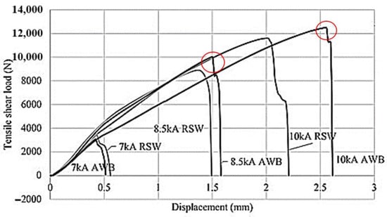
Figure 10.
Force–displacement curves for RSW DP600 + DP600 and WB DP600 + DP600.
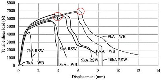
Figure 11.
Force–displacement curves for RSW DP600 + 316SS and WB DP600 + 316SS.
Figure 12 shows the energy absorbed by the RSW and WB joints before failure in Nmm (1 Nmm = 0.001 J) for different currents.
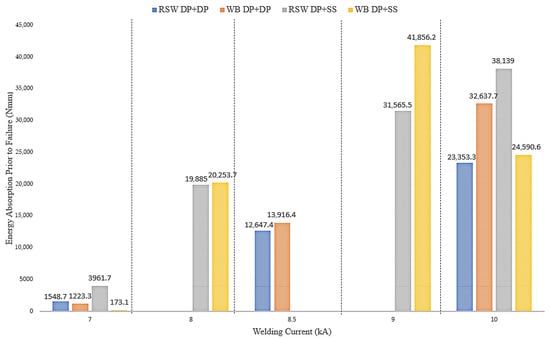
Figure 12.
Energy absorption prior to failure for RSW joints and WB joints.
Figure 10 and Figure 12 show that at a 7 kA welding current, the RSW DP600 + DP600 joint had higher tensile shear strength and energy absorption before failure, respectively, compared to the WB DP600 + DP600 joint. This can be related to the weld diameters of 2.23 mm and 1.89 mm, respectively, for both these joints in Table 5. Similarly, Figure 11 and Figure 12 show that at a 7 kA welding current, the RSW DP600 + 316SS joint had higher tensile shear strength and energy absorption before failure, respectively, compared to the WB DP600 + 316SS joint. As seen in Table 5, the RSW joint had a weld diameter of 2.08 mm, and no weld was developed in the WB joint. Figure 12 also shows that the RSW DP600 + 316SS joint has a higher energy absorption compared to the RSW DP600 + DP600 joint. This can be attributed to the brittle characteristic of the DP600 due to the formation of a martensitic phase in the weld fusion zone during rapid cooling in the welding process [51]. The stainless steel’s austenitic structure lowered the hardness of the HAZ compared to the martensitic structure in the HAZ of DP600. Therefore, the DP600 + DP600 joint was less tough compared to the DP600 + 316SS joint. Failure was always initiated at the HAZ of the DP600 [52].
Figure 10 and Figure 12 show that the WB joints had higher tensile shear strength and energy absorption before failure at higher welding currents than the RSW joint. Similarly, Figure 11 and Figure 12 show that, except for 10 kA current, at other welding currents greater than 7 kA, WB joints had higher tensile shear strength and energy absorption capacity compared to RSW joints. At 10 kA welding current, Table 5 shows that the WB joint had a diameter greater than the weld diameter from the RSW joint. The reason for this low energy absorption before failure in the WB joint compared to the RSW joint was weld expulsion. Expulsion was observed during the welding of WB joints at 10 kA (refer to 3.3 Fracture modes of spot-welded and weld-bonded joints). Expulsion due to extreme heat at a high current will expel molten metal from the weld area, creating porosity or cavities within the weld nugget or reducing the weld nugget diameter [53].
The adhesive affected the heat generation during welding for different welding currents. The energy balance in the weld joint—Equation (3) and contact resistance—Equation (4) [23] explain this observation.
where c—specific heat coefficient of steel, m—mass of steel, ∆T—increase in temperature during time ∆t, I—welding current, RD—dynamic resistance of weld joint including the bulk resistances of steels and adhesive, and the contact resistance between steels and adhesive (RCA). As in Equation (1), the first term on the right side of Equation (3) refers to the heat generation during welding and Ql—heat losses during welding.
where ρ—resistivity coefficient of steel, ρf—film resistivity, sf—film thickness, ka—influence coefficient of adhesive (based on adhesive type and adhesive distribution on steel surface), n—number of contact spots, H—hardness of faying steel, and F—electrode force. Assuming ρf and sf are zero, with only ka, the RCA increases due to the adhesive at the interface, which increases the static contact resistance, leading to an increase in the RD. This, in turn, will increase the heat generation.
cm∆T = I2. RD∆t + Ql
Sun et al. [54] reported that the effect of adhesive on dynamic resistance is only within the initial 75 ms, after which the thermal decomposition and nugget growth dominate the process and decrease the dynamic resistance. As in Equation (3), at a higher current, the increase in I2 and the addition of in Equation 4 for the WB joint, assisted in the increase in heat generation during welding due to the increase in RD. This led to the formation of bigger-diameter weld nuggets in WB joints. For a dissimilar WB joint, expulsion was observed at 10 kA due to overheating, and the electrode force could not suppress the spot weld force created by the increase in nugget diameter [55,56]. On the contrary, using Equations (3) and (4), at a lower current, the lower thermal conductivity of the adhesive reduced the change in temperature ∆T for the same time ∆t, hence the increase in heat generation was slower in WB joints despite the addition of . Therefore, the dynamic resistance was lower, and less heat generation occurred during welding for the same weld time as for the RSW joints. For a dissimilar WB joint, thermal conductivity differences between dissimilar steels and the lower heat generation were insufficient to produce a weld at 7 kA (the lowest current).
3.3. Fracture Modes of Spot-Welded and Weld-Bonded Joints
Spot weld failure modes will transition from interfacial failure to partial interfacial failure and finally to pullout failure with the increase in welding current within the weldability lobe, and this transition is proportional to the rise in absorption energy before failure [57,58]. DP600 joints produced interfacial or partial interfacial failure due to the brittle nature of the welds [59]. In this work, all RSW DP600 + DP600 joints exhibited interfacial failure at 7 kA and 8.5 kA welding currents and partial interfacial failure at 10 kA welding current. Figure 13a,b shows the failure modes for spot weld joints made from 7 kA and 10 kA welding current. Figure 14a shows that at a 7 kA welding current, the dissimilar steel RSW joint showed smaller weld nugget formation and failed via interfacial failure. The wider area of the heat-affected zone was observed on the DP600 side, and a tiny formation of weld on the stainless-steel side, as AISI 316 stainless steel has high resistance to current compared to DP600 steel. At 10 kA welding current, joint failure started from the DP600 HAZ, and the specimen failed with pullout failure. Metal expulsion was observed in the 10 kA specimen as seen in Figure 14b. All WB DP600 + DP600 joints failed through interfacial failure, except for the joint at 10 kA welding current that failed through partial interfacial failure, as shown in Figure 15a. The WB DP600 + 316SS joint did not form a weld nugget at the lowest welding current of 7 kA. WB DP600 + 316SS joint at 8 kA failed through interfacial failure, but WB DP600 + 316SS joints at 9 kA and 10 kA (Figure 15b) welding currents failed by pull-out failure. The failure modes in this study are tabulated in Table 6.
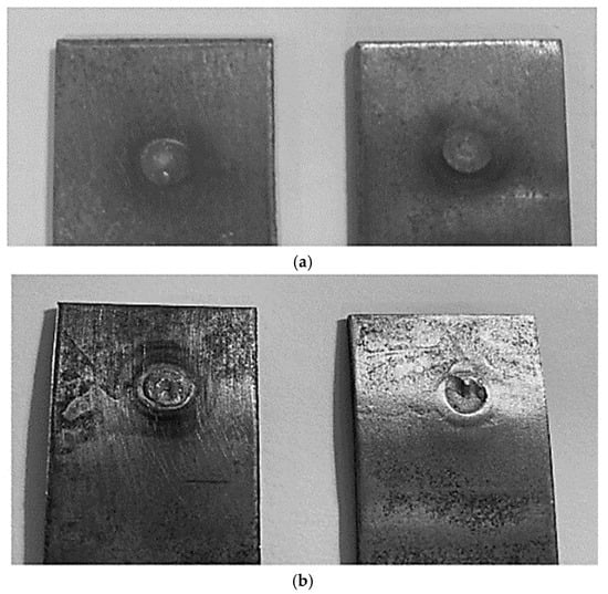
Figure 13.
DP600 + DP600 spot weld failure (a) interfacial failure at 7 kA current, and (b) partial interfacial failure at 10 kA current.

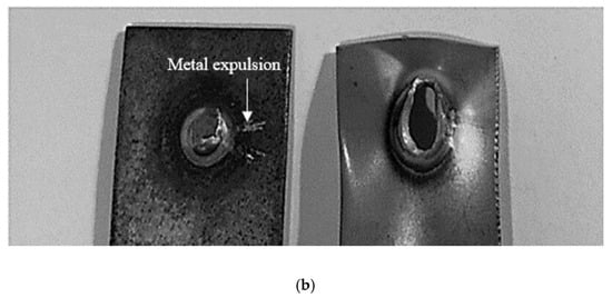
Figure 14.
DP600 + 316SS spot weld failure (a) interfacial failure at 7 kA current, and (b) pull-out at 10 kA current.
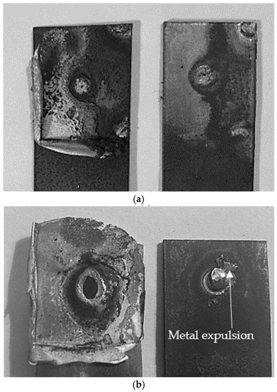
Figure 15.
(a) WB DP600 + DP600 partial interfacial failure at 10 kA and (b) WB DP600+ 316SS pull-out failure at 10 kA current.
Table 6.
Fracture modes for RSW and WB joints at different welding currents.
Except for the WB DP600 + 316SS joint at 7 kA welding current, the RSW and WB joints for the same welding current experienced the same fracture modes. The use of adhesive in the WB joints narrowed the weld lobe [60], and this was observed within the range of welding current selected in the dissimilar DP600 + 316SS joints. The weldability region in dissimilar WB joints was observed within 8 kA and 9 kA, while the weldability region in dissimilar RSW joints was within 7 kA to 10 kA. The change in the weldability lobe for DP600 + DP600 RSW and WB joints was not noticed due to the possibility that this change is out of the scope of the current range used, and within the selected current range, the same failure modes were observed. The adhesive deformed during the tensile shear loading and failed via delamination from one sheet and remained on the other sheet, as shown in Figure 15a,b. Referring to Figure 10 and Figure 11, it was noticed that the force–displacement curves of WB joints that failed through partial interfacial failure and pull-out failure showed a sudden drop in tensile shear load from the maximum load and a second peak before further reduction of load till weld fracture.
3.4. Stress Analysis on Spot-Welded and Weld-Bonded Joints
The applied tensile shear force acting on the FEA model is equal to the force acting on the grip, as shown in Figure 5a. The maximum tensile shear forces for both RSW and WB joints at 10 kA are 11,600 N and 12,530 N, respectively (Figure 10). Simulation results showed the force reactions along the x-axis for RSW and WB joints as 5865.6 N and 6332.8 N, respectively. Considering only one half of the specimen was modelled due to symmetry, these values will be multiplied by two; therefore, they will be 11,731.2 and 12,665.6 N. These values have good agreement with the values obtained experimentally. Figure 16 compares the radial stress gradient across the weld nugget diameter for both RSW and WB joints obtained from the finite element analysis. The radial stress gradients for both joints had similar characteristics and were symmetrical at the weld centre. However, the radial stresses in WB joints are lower than in the RSW joints.
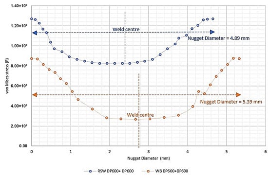
Figure 16.
Stress gradients across weld diameter for RSW and WB DP600 + DP600 joints at 10 kA.
The radial stress gradient across the weld diameter and the differences in stress gradient between RSW and WB joints, as given in Figure 16, can be explained by analyzing the sheets’ directional deformations along the Z axis. Figure 17a shows the highest Von Mises stress at the HAZ and circumference of the weld nugget. This stress is due to the metal sheets’ maximum directional deformation along the Z-axis of 2.64 mm, as seen in Figure 17a. The directional deformation along the Z-axis was identified as the bending of the metal sheets. The bending of the metal sheets created sharp edges at the transition of HAZ to the weld circumference, forming a stress concentration region. This stress concentration region caused crack formation that propagated to the weld nugget, leading to weld failure [61]. Figure 17b confirmed this statement; the bending of sheets, observed in the fracture mode analyses, showed a crack from the HAZ that progressed into the weld nugget, causing a pull-out failure. The stress gradient in Figure 17c showed the Von Mises stress reduction from the circumference of the weld to the center of the weld nugget.
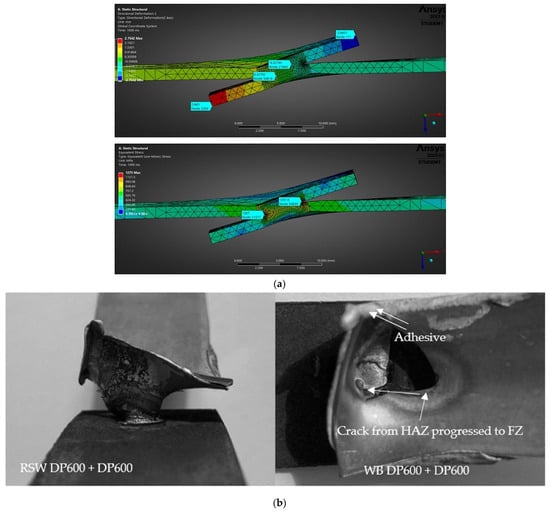
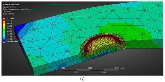
Figure 17.
(a) Directional deformation at Z-axis and maximum Von Mises stress at HAZ—weld circumference transition zone for RSW joint, (b) sheets bending and crack progression from HAZ to FZ, and (c) Von Mises stress reduces from the nugget circumference to the nugget center.
The metal sheets’ maximum directional deformation along the Z-axis in the WB joints, as seen in Figure 18a, was 1.13 mm, lower compared to the metal sheets’ maximum directional deformation along the Z-axis in the RSW joints. A stress concentration region was observed at the transition of HAZ to the weld circumference in Figure 18a. However, the lower sheet bending in the WB joint and the adhesive layer between sheets prevented the formation of sharp edges and reduced the maximum Von Mises stress compared to the maximum Von Mises stress observed in the RSW joint. The simulation also showed thinning of the adhesive layer closer to the spot weld with Von Mises stress of 1.05 MPa, but thicker at the edges of the metal sheets with Von Mises stress of 3.11 MPa. The stress in the adhesive is significantly lower compared to the 869.5 MPa stress at the transition of HAZ to weld circumference, indicating the weld nugget played a major role in reducing the bending of the metal sheets. The increase in nugget diameter in the WB joints compared to the RSW joints increased the tensile shear strength [62] of WB joints, as shown in Figure 10. A spot weld with higher strength reduced the sheet bending. The stress gradient in Figure 18b shows the Von Mises stress reduction from the circumference of the weld to the center of the weld nugget.

Figure 18.
(a) Directional deformation at Z-axis and maximum von Mises stress at HAZ—weld circumference transition zone for WB joint, and (b) von Mises stress reduces from the nugget circumference to the nugget center.
Sadowski et al. [30] reported that the failure in WB joints involved degradation of adhesive, adhesive failure, and finally failure of the spot weld. The WB joint simulation reflected this failure with the initial deformation of the adhesive with a thinner layer closer to the weld and a thicker layer at the sheet’s edges. The maximum stress of 3.11 MPa at the edges of metal sheets is higher than the maximum tensile strength of 3 MPa for Sikaflex 252 as given in Table 2. The adhesive failed through delamination, followed by the failure of the spot weld as observed in the fractured specimen in Figure 15a,b. The failure mechanism in WB joints due to tensile shear loading differed from the direct failure of spot welds in RSW joints. However, upon failure of the adhesive, the failure modes of both joints are the same, as shown in Table 6. The difference in failure mechanism between the RSW and WB joints was also observed in the force–displacement curves for RSW DP600 + DP600 and WB DP600 + DP600. The WB DP600 + DP600 curve showed a sudden drop in load from the maximum load, indicating adhesive failure. The second peak was due to the deformation of the weld, and the load later dropped drastically due to spot weld’s brittle fracture. In RSW DP600 + DP600, after the maximum load, the load dropped solely due to spot weld failure.
4. Conclusions
Comparison studies on spot weld properties between RSW joints and WB joints for similar DP600 + DP600 and dissimilar DP600 + 316SS were conducted. The adhesive improved the tensile shear strength and toughness of WB joints compared to RSW joints. The same observation applied to both similar and dissimilar steel joints. The adhesive contributed to higher heat generation by increasing the dynamic resistance at a higher current. However, the lower thermal conductivity of the adhesive at a lower current limited the generation of heat and produced unfavorable weld quality. The use of adhesive showed narrowing of the weldability lobe and changes in failure mode in RSW and WB dissimilar steel joints. Because of the selected weldability lobe for RSW and WB similar steel joints, the weldability lobe change could not be observed, and the RSW and WB similar steel joints showed the same failure mode. The use of adhesive reduced the stress gradient across the weld nugget. WB joints had bigger diameters and higher tensile strength spot welds that minimized sheet bending in tensile shear loading and reduced the Von Mises stress at the stress concentration region. Therefore, with the increased bond area and bigger diameter weld, WB joints had superior mechanical properties compared to RSW joints.
Author Contributions
Conceptualization, A.A.; methodology, C.P.P. and A.A.; validation, C.P.P., A.K.B. and A.P.; formal analysis, A.K.B. and A.P.; investigation, A.A. and A.K.B.; resources, A.P.; writing—original draft preparation, A.A.; writing—review and editing, C.P.P., A.K.B. and A.P.; visualization, A.A.; supervision, A.P.; project administration, C.P.P. All authors have read and agreed to the published version of the manuscript.
Funding
This research received no external funding.
Data Availability Statement
The original contributions presented in the study are included in the article, further inquiries can be directed to the corresponding authors.
Conflicts of Interest
Author Cosmas Pandit Pagwiwoko was employed by the company R&D Syos Aerospace from the end of July 2025. The remaining authors declare that the research was conducted in the absence of any commercial or financial relationships that could be construed as a potential conflict of interest.
References
- Taub, A.; Moor, E.D.; Luo, A.; Matlock, D.K.; Speer, J.G.; Vaidya, U. Materials for Automotive Lightweighting. Annu. Rev. Mater. Res. 2019, 49, 327–359. [Google Scholar] [CrossRef]
- Andersson, O.; Semere, D.; Melander, A.; Arvidsson, M.; Lindberg, B. Digitalization of Process Planning of Spot Welding in Body-in-white. Procedia CIRP 2016, 50, 618–623. [Google Scholar] [CrossRef]
- Soomro, I.A.; Pedapati, S.R.; Awang, M. A review of advances in resistance spot welding of automotive sheet steels: Emerging methods to improve joint mechanical performance. Int. J. Adv. Manuf. Technol. 2021, 118, 1335–1366. [Google Scholar] [CrossRef]
- ANSI/AWS D8.1M: 2021; Specification for Automotive Weld Quality Resistance Spot Welding of Steel. 3rd ed. American Welding Society: Miami, FL, USA, 2021.
- Chen, N.; Wang, H.P.; Wang, M.; Carlson, B.E.; Sigler, D.R. Schedule and electrode design for resistance spot weld bonding Al to steels. J. Mater. Process. Technol. 2019, 265, 158–172. [Google Scholar] [CrossRef]
- Das, T.; Paul, J. Interlayers in Resistance Spot-Welded Lap Joints: A Critical Review. Metallogr. Microstruct. Anal. 2021, 10, 3–24. [Google Scholar] [CrossRef]
- Ren, S.; Ma, Y.; Saeki, S.; Iwamoto, Y.; Chen, Y.; Ma, N. Fracture mechanism and strength evaluation of Al5052/CFRP joint produced by coaxial one-side resistance spot welding. Compos. Struct. 2020, 252, 112766. [Google Scholar] [CrossRef]
- Xu, H.; Fang, X. Resistance insert spot welding: A new joining method for thermoplastic FRP–steel component. Weld. World 2023, 67, 1733–1752. [Google Scholar] [CrossRef]
- Lara, B.; Giorjao, R.; Ramirez, A. Resistance spot welding of printed interlayers to join Al-Fe sheets. Sci. Technol. Weld. Join. 2023, 28, 18–26. [Google Scholar] [CrossRef]
- Ren, S.; Ma, Y.; Ma, N. Development of FEA-ANN-Integrated Approach for Process Optimization of Coaxial One-Side Resistance Spot Welding of Al5052 and CFRP. J. Manuf. Sci. Eng. 2022, 144, 011004. [Google Scholar] [CrossRef]
- Zhang, W.; Zhang, K.; Yang, Y.; Sun, X.; Yu, S.; Li, Y.; Yu, Y.; Sun, D. A novel dissimilar resistance spot welding of Ti6Al4V alloy and 316L stainless steel via copper as interlayer by using optimal electrodes. J. Mater. Res. Technol. 2024, 33, 5425–5437. [Google Scholar] [CrossRef]
- Dharaiya, V.; Panchal, A.; Acharya, G.D. Investigating feasibility of interlayers in Resistance Spot Welding of low-carbon steel sheets. SN Appl. Sci. 2021, 3, 749. [Google Scholar] [CrossRef]
- Karim, M.; Park, Y.D. A Review on Welding of Dissimilar Metals in Car Body Manufacturing. J. Weld. Join. 2020, 38, 8–23. [Google Scholar] [CrossRef]
- Varga, J.; Brezinová, J.; Brezina, J. Quality Analysis of Bonded Joints in the Renovation of Plastic Automotive Parts. Appl. Sci. 2024, 14, 2–3. [Google Scholar] [CrossRef]
- Goushegir, S.M.; Santos, J.F.D.; Amancio-Filho, S.T. Friction Spot Joining of aluminum AA2024/carbon-fiber reinforced poly(phenylene sulfide) composite single lap joints: Microstructure and mechanical performance. Mater. Des. 2014, 54, 196–206. [Google Scholar] [CrossRef]
- Jeevi, G.; Nayak, S.K.; Kader, M.A. Review on adhesive joints and their application in hybrid composite structures. J. Adhes. Sci. Technol. 2019, 33, 1497–1520. [Google Scholar] [CrossRef]
- Maggiore, S.; Banea, M.D.; Stagnaro, P.; Luciano, G. A Review of Structural Adhesive Joints in Hybrid Joining Processes. Polymers 2021, 13, 3961. [Google Scholar] [CrossRef] [PubMed]
- Lambiase, F.; Scipioni, S.I.; Lee, C.J.; Ko, D.C.; Liu, F. A State-of-the-Art Review on Advanced Joining Processes for Metal-Composite and Metal-Polymer Hybrid Structures. Materials 2021, 14, 1890. [Google Scholar] [CrossRef]
- Antelo, J.; Akhavan-Safar, A.; Carbas, R.J.C.; Marques, E.A.S.; Goyal, R.; da Silva, L.F.M. Replacing welding with adhesive bonding: An industrial case study. Int. J. Adhes. Adhes. 2022, 113, 103064. [Google Scholar] [CrossRef]
- Ufferman, B.; Abke, T.; Barker, M.; Vivek, A.; Daehn, G.S. Mechanical properties of joints in 5052 aluminum made with adhesive bonding and mechanical fasteners. Int. J. Adhes. Adhes. 2018, 83, 96–102. [Google Scholar] [CrossRef]
- Braga, D.F.O.; Maciel, R.; Bergmann, L.; da Silva, L.F.M.; Infante, V.; Santos, J.F.D.; Moreira, P.M.G.P. Fatigue performance of hybrid overlap friction stir welding and adhesive bonding of an Al-Mg-Cu alloy. Fatigue Fract. Eng. Mater. Struct. 2019, 42, 1262–1270. [Google Scholar] [CrossRef]
- Manladan, S.M.; Yusof, F.; Ramesh, S.; Fadzil, M.; Luo, Z.; Ao, S. A review on resistance spot welding of aluminum alloys. Int. J. Adv. Manuf. Technol. 2017, 90, 605–634. [Google Scholar] [CrossRef]
- Zhao, Y.; Zhang, Y.; Lai, X. Effect of epoxy adhesive on nugget formation in resistance welding of SAE1004/DP600/DP780 steel sheets. Materials 2018, 11, 18–28. [Google Scholar] [CrossRef] [PubMed]
- Cavezza, F.; Boehm, M.; Terryn, H.; Hauffman, T. A Review of Adhesively Bonded Aluminium Joints in the Automotive Industry. Metals 2020, 10, 730. [Google Scholar] [CrossRef]
- Burchardt, B. Automotive Industry. In Handbook of Adhesion Technology; Springer: Berlin/Heidelberg, Germany, 2011; pp. 1186–1212. [Google Scholar] [CrossRef]
- Hayat, F. Comparing Properties of Adhesive Bonding, Resistance Spot Welding, and Adhesive Weld Bonding of Coated and Uncoated DP 600 Steel. J. Iron Steel Res. Int. 2011, 18, 70–78. [Google Scholar] [CrossRef]
- Xu, W.; Chen, D.L.; Liu, L.; Mori, H.; Zhou, Y. Microstructure and mechanical properties of weld-bonded and resistance spot welded magnesium-to-steel dissimilar joints. Mater. Sci. Eng. A 2012, 537, 11–24. [Google Scholar] [CrossRef]
- Bartczak, B.; Mucha, J.; Trzepieciński, T. Stress distribution in adhesively-bonded joints and the loading capacity of hybrid joints of car body steels for the automotive industry. Int. J. Adhes. Adhes. 2013, 45, 42–52. [Google Scholar] [CrossRef]
- Pereira, A.M.; Ferreira, J.A.M.; Antunes, F.V.; Bartolo, P.J. Assessment of the fatigue life of aluminium spot-welded and weld-bonded joints. J. Adhes. Sci. Technol. 2014, 28, 1432–1450. [Google Scholar] [CrossRef]
- Sadowski, T.; Golewski, P.; Kneć, M. Experimental investigation and numerical modelling of spot welding–adhesive joints response. Compos. Struct. 2014, 112, 66–77. [Google Scholar] [CrossRef]
- Costa, H.R.M.; Reis, J.M.L.; Souza, J.P.B.; Pacheco, P.M.C.L.; Aguiar, R.A.A.; Barros, S.D. Experimental investigation of the mechanical behaviour of spot welding–adhesives joints. Compos. Struct. 2015, 133, 847–852. [Google Scholar] [CrossRef]
- Marques, G.P.; Campilho, R.D.S.G.; da Silva, F.J.G.; Moreira, R.D.F. Adhesive selection for hybrid spot-welded/bonded single-lap joints: Experimentation and numerical analysis. Compos. Part B 2016, 84, 248–257. [Google Scholar] [CrossRef]
- Piwowarczyk, T.; Korzeniowski, M. Quality analysis of hybrid adhesive-spot welded joints. J. Adhes. Sci. Technol. 2018, 32, 656–672. [Google Scholar] [CrossRef]
- Manladan, S.M.; Hamza, M.F.; Ramesh, S.; Luo, Z. Lap-Shear Performance of Weld-Bonded Mg Alloy and Austenitic Stainless Steel in Three-Sheet Stack-Up. Chin. J. Mech. Eng. 2024, 37, 70. [Google Scholar] [CrossRef]
- Kishore, K.; Kumar, P.; Mukhopadhyay, G. Resistance spot weldability of galvannealed and bare DP600 steel. J. Mater. Process. Technol. 2019, 271, 237–248. [Google Scholar] [CrossRef]
- ANSI/AWS/SAE/D8.9-97; Recommended Practice for Test Methods for Evaluating the Resistance Spot Welding Behavior of Automotive Sheet Steel Materials. American Weldimg Society: Miami, FL, USA, 1997.
- Product Data Sheet-Sikaflex®-252, Version 03.01 (04-2023); Elastic Adhesive for Vehicle Assembly Bonding. Sika Industry: Baar, Switzerland, 2023. Available online: https://industry.sika.com/dam/dms/gb01/2/sikaflex_-252.pdf (accessed on 12 February 2025).
- ISO 18278-1; Resistance Welding—Weldability, Part 1—General Requirements for the Evaluation of Welability for Resistance Spot Seam and Projection Welding of Metallic Materials. International Standards Institute: Geneva, Switzerland, 2022.
- Pandya, K.S.; Grolleau, V.; Roth, C.C.; Mohr, D. Fracture response of resistance spot welded dual phase steel sheets: Experiments and modeling. Int. J. Mech. Sci. 2020, 187, 105869. [Google Scholar] [CrossRef]
- Zhao, L.; Lu, Y.; Xiong, Z.; Sun, L.; Qi, J.; Yuan, X.; Peng, J. Mechanical properties and nugget evolution in resistance spot welding of Zn–Al–Mg galvanized DC51D steel. High Temp. Mater. Process. 2023, 42, 20220243. [Google Scholar] [CrossRef]
- Janardhan, G.; Mukhopadhyay, G.; Dutta, K. Failure mechanism of resistance spot-welded DP600 steel under high cycle fatigue. Mater. Today Proc. 2022, 59, 1666–1671. [Google Scholar] [CrossRef]
- Nguyen, K.; Montans, F.J. Plane stress constrained multiplicative hyperelasto-plasticity with nonlinear kinematic hardening. Consistent theory based on elastic corrector rates and algorithmic implementation. Int. J. Plast. 2019, 128, 102592. [Google Scholar] [CrossRef]
- Cruz, D.J.; Pereira, A.F.G.; Simoes, V.M.; Amaral, R.L.; Santos, A.D.; Oliveira, M.C. Work Hardening of Metallic Sheets Under Tension-Compression and Simple Shear Reverse Loading. Key Eng. Mater. 2022, 926, 2012–2021. [Google Scholar] [CrossRef]
- Karpiesiuk, J. Young’s Modulus and Poisson’s Ratio of Polyurethene Adhesive in Lightweight Floor System. Mod. Approaches Mater. Sci. 2020, 2, 1–5. [Google Scholar] [CrossRef]
- Bhat, S.D.; Vijeesh, V.; Acharya, P.; Rao, M. Investigation of thin sheet stainless steel resistance spot welds: Effect of weld current on nugget failure and microstructure. Mater. Today Proc. 2021, 35, 361–365. [Google Scholar] [CrossRef]
- Jain, V.K.S.; Sarma, V.S.; Amirthalingam, M. Resistance spot welding behaviour of novel medium manganese (M-Mn) steels—Role of welding parameters on weld microstructure and mechanical properties. J. Manuf. Process. 2023, 101, 1405–1418. [Google Scholar] [CrossRef]
- Morales-Sánchez, G.; Collazo, A.; Doval-Gandoy, J. Influence of the process parameters on the quality and efficiency of the resistance spot welding process of advanced high-strength complex-phase steels. Metals 2021, 11, 1545. [Google Scholar] [CrossRef]
- Espinel-Hernández, A.; Sanchez-Orozco, M.; Sanchez-Roca, A.; Caputi, L.S.; Oliveira-Villarinho, L.; Carvajal-Fals, H. Influence of zinc coating on nugget development and mechanical properties in dissimilar welded joints DP600—AISI304 obtained by the RSW process. Dyna 2022, 89, 121–129. [Google Scholar] [CrossRef]
- Pouranvari, M.; Ranjbarnodeh, E. Resistance Spot Welding Characteristic of Ferrite-Martensite DP600 Dual Phase Advanced High Strength Steel-Part III: Mechanical Properties. World Appl. Sci. J. 2011, 15, 1521–1526. [Google Scholar]
- Soomoro, I.A.; Pedapati, S.R. Application of in situ post weld heat treatment using double pulse technology and its effect on microstructure and mechanical performance of resistance spot welded HSLA350 steel. Int. J. Adv. Manuf. Technol. 2019, 105, 3249–3260. [Google Scholar] [CrossRef]
- Hernández, A.E.; Villarinho, L.O.; Ferraresi, V.A.; Orozco, M.S.; Roca, A.S.; Fals, H.C. Optimization of resistance spot welding process parameters of dissimilar DP600/AISI304 joints using the infrared thermal image processing. Int. J. Adv. Manuf. Technol. 2020, 108, 211–221. [Google Scholar] [CrossRef]
- Hernandez, A.E.; Roca, A.S.; Fals, H.C.; Ferraresi, V.A.; Vilarinho, L.O. Influence of polarity on mechanical properties of dissimilar resistance spot welds of DP 600/AISI 304 steels. Sci. Technol. Weld. Join. 2016, 21, 607–613. [Google Scholar] [CrossRef]
- Stavropoulos, P.; Sabatakakis, K. Quality Assurance in Resistance Spot Welding: State of Practice, State of the Art, and Prospects. Metals 2024, 14, 185. [Google Scholar] [CrossRef]
- Sun, X.; Zhang, Q.; Wang, S.; Han, X.; Li, Y.; David, S.A. Effect of adhesive sealant on resistance spot welding of 301L stainless steel. J. Manuf. Process. 2020, 51, 62–72. [Google Scholar] [CrossRef]
- Valaee-Tale, M.; Sheikhi, M.; Mazaheri, Y.; Ghaini, F.M.; Usefifar, G.R. Criterion for predicting expulsion in resistance spot welding of steel sheets. J. Mater. Process. Technol. 2020, 275, 116329. [Google Scholar] [CrossRef]
- Arumugam, A.; Baharuddin, A. Effect of Force Control during Spot Welding on Weld Properties. Int. J. Sci. Res. Publ. 2014, 4, 1–6. [Google Scholar]
- Tamizi, M.; Pouranvari, M.; Movahedi, M. The Role of HAZ Softening on Cross-Tension Mechanical Performance of Martensitic Advanced High Strength Steel Resistance Spot Welds. Metall. Mater. Trans. A 2021, 52, 655–667. [Google Scholar] [CrossRef]
- Arumugam, A.; Pramanik, A. A study of spot weld pull-out failure (PF) mechanism under different loading conditions for stainless steel and mild steel joints. Aust. J. Mech. Eng. 2020, 20, 603–616. [Google Scholar] [CrossRef]
- Sivaraj, P.; Seeman, M.; Kanagarajan, D.; Seetharaman, R. Influence of welding parameter on mechanical properties and microstructural features of resistance spot welded dual phase steel sheets joint. Mater. Today: Proc. 2020, 22, 558–562. [Google Scholar] [CrossRef]
- Zhang, Y.S.; Sun, H.T.; Chen, G.L.; Lai, X.M. Comparison of mechanical properties and microstructure of weld nugget between weld-bonded and spot-welded dual-phase steel. Proc. Inst. Mech. Engineers. Part B J. Eng. Manuf. 2009, 223, 1341–1350. [Google Scholar] [CrossRef]
- Dorribo, D.; Greve, L.; Diez, P.; Arias, I.; Larrayoz-Izcara, X. Numerical estimation of the bearing capacity of resistance spot welds in martensitic boron steels using a J-integral fracture criterion. Theor. Appl. Fract. Mech. 2018, 96, 497–508. [Google Scholar] [CrossRef]
- MKhan, F.; Sharma, G.; Dwivedi, D.K. Weld-bonding of 6061 aluminium alloy. Int. J. Adv. Manuf. Technol. 2015, 78, 863–873. [Google Scholar] [CrossRef]
Disclaimer/Publisher’s Note: The statements, opinions and data contained in all publications are solely those of the individual author(s) and contributor(s) and not of MDPI and/or the editor(s). MDPI and/or the editor(s) disclaim responsibility for any injury to people or property resulting from any ideas, methods, instructions or products referred to in the content. |
© 2025 by the authors. Licensee MDPI, Basel, Switzerland. This article is an open access article distributed under the terms and conditions of the Creative Commons Attribution (CC BY) license (https://creativecommons.org/licenses/by/4.0/).