Abstract
As research on new, lightweight energy vehicles continues to develop, the application of high-strength steel sheets with tensile strength greater than 1 GPa and their mechanical clinching technology, which is associated with aluminum alloys, has emerged as a new research focus. However, due to the challenges associated with the cold deformation of high-strength steel, conventional mechanical clinching processes often fail to establish effective joint interlocking, resulting in weak connections. This study proposes a center-punching mechanical clinching process for connecting DP980 high-strength steel to AL5052 aluminum alloy. The mechanical evolution during the forming process was analyzed via finite element simulation. An orthogonal experimental design was employed to optimize key geometric parameters of the punch and die, yielding the optimal configuration for the mold. Mechanical testing of the joint demonstrated average pull-out force and pull-shear forces of 1124 N and 2179 N, respectively, confirming the proposed process’s ability to successfully connect high-strength steel and aluminum alloy.
1. Introduction
In recent years, automotive light weighting has emerged as a critical technological pathway for energy conservation, emission reduction, and enhanced energy efficiency, driving breakthroughs in new materials and advanced manufacturing processes [1,2]. Currently, high-strength steel and aluminum alloys are widely recognized as ideal materials for automotive light weighting applications [3]. In automotive design, the rational integration of high-strength steel and aluminum alloys enables effective performance-differentiated control of body structural components, meeting the multifaceted requirements of safety and structural integrity for occupant compartments. Within the domain of joining dissimilar lightweight alloy sheets, conventional welding techniques face inherent limitations such as thermal stress-induced deformation and material degradation, while clinched connections introduce additional weight due to auxiliary fasteners. These challenges have made cold joining and forming technologies a focal point of research on lightweight design [4,5]. In particular, self-piercing rivetless connection, characterized by its lack of a need for rivets, its nonexistent heat input, and its ability to facilitate single-step formation, demonstrates unique value in thin-sheet structure manufacturing [6].
Several studies have addressed the clinching process between high-strength steel (with tensile strength exceeding 1 GPa) and light alloys. Lee et al. [7] developed a new technology called “hole clinching”, which involves pre-drilling holes in high-strength, low ductility material and then connecting it with the ductile material without using rivets. High-quality joints were created with this technology. Han et al. [8] used numerical methods and experiments to study the thermal-assisted hole clinching between magnesium alloys and 22MnB5 high-strength steel. ABE et al. [9] found that traditional clinching methods could not effectively connect steel with tensile strength exceeding 1 GPa and thus proposed a clinching process for high-strength steel sheet pre-forming, which increased the interlocking value and improved the quality of the riveted joint. FU et al. [10] conducted research on the pre-forming clinching of DP980 high-strength steel and AL5052 aluminum alloy. Due to the greater resistance of the bottom steel sheet, the upper aluminum sheet overflowed from the neck thickness, causing the upper edge of the joint to separate and significantly weakening the joint. To strengthen the connection, a press platform structure was added to the lower end of the clinching punch, which sealed the neck gap during clinching and compacted the joint. Experimental verification demonstrated that this method could be used to establish high-quality joints. Zhuang Weimin et al. [11] proposed a hot clinching quenching (HRQ) clinching process for heterogeneous materials, utilizing the good plastic deformation ability of 22MnB5 at high temperatures to achieve effective clinching between 22MnB5 high-strength steel and 7075 aluminum alloy.
However, the above methods have a certain impact on processing efficiency. For example, for the “hole clinching” technology, the center of the punch and the center of the hole of the steel sheet need to be accurately positioned, otherwise the light alloy sheet is easy to break. For the pre-forming clinching method, the preformed and clinched are processed under different molds, and the mold needs to be replaced after the preforming is completed, which affects the processing efficiency. The thermal-assisted clinching process is adopted, which the sheet needs to be heated to a reasonable temperature every time clinching, and the processing efficiency is slow.
Regarding the optimization of the clinching process, some scholars have employed optimization algorithms to study the appropriate process parameters. ROUX et al. [12] utilized the global optimization technique based on the Kriging model to optimize the final connection strength of the clinching components. Through global optimization, the clinching tensile strength was increased to 13.5%, while the clinching shear strength was increased to 46.5%. Chen et al. [13] reshaped clinched joints using the orthogonal test method. By simulating 25 different combinations, they identified the optimal combination for reshaping rivet geometric parameters. In their experiments, the average cross-tensile strength and shear strength increased from 957.9 N to 1154.9 N, and from 1229.4 N to 2757.3 N. Oudjene et al. [14] proposed an effective strategy for improving the accuracy of RSM near the global optimum. Using the ABAQUS finite element code, they conducted an analysis based on the clinching forming process. The geometric dimensions of the punch and the mold were optimized to enhance the tensile strength of the joint. LAMBISE et al. [15] proposed a retractable die-clinching tool, predicting the influence of geometric shapes on locking parameters through a finite element model, and recursively optimized the tool design. To reduce the number of finite element simulations required, an artificial neural network (ANN) was used to predict the joint-forming behavior. ABE et al. [16] discussed optimizing the material flow pattern by changing the shape of the clinching tool and established a more formable clinching connection method for high-strength steel and aluminum alloys.
In conclusion, thus far, most researchers have utilized multi-step or heat-assisted clinching connection technologies to connect high-strength steel sheets. This has affected the improvement of processing efficiency in the actual production of aluminum alloys and high-strength steel sheets.
This article presents a new type of clinching process for heterogeneous thin sheets of high-strength steel and aluminum alloy with tensile strength exceeding 1 GPa: the center-punching mechanical clinching process (CPMC). The upper die used in this process integrates two structures of punching and clinching, and the lower die is composed of a combination of a die and a button die, which can complete the punching and clinching sequence forming in one step, without changing the mold and heating sheet. It allows us to complete the sequential formation of punching and clinching in a single, more efficient operation. Using 1.2 mm thick DP980 steel and 1.5 mm AL5052 aluminum alloy sheets as the research objects, the finite element simulation and orthogonal experiment combination method were used to optimize the relevant geometric parameters of the punch and die and to verify the feasibility of the center-punching mechanical clinching process.
2. Mechanism and Process of Plastic Formation of CPMC
2.1. Mechanics of Plastic Formation of CPMC
A mechanical analysis of the traditional clinching process is shown in Figure 1, which illustrates that the deformation of the weaker steel sheet is mainly achieved through deep drawing and extrusion. Since the steel sheet is, comparatively, much stronger than the aluminum alloy, deformation becomes challenging, preventing the joint from forming an effective interlock. In addition, when the deep drawing depth is relatively large, the bottom of the high-strength steel sheet is prone to fracture, potentially resulting in joint connection failure. To solve these problems, the proposed center punching clinching process adopts the circular hole flanging procedure during the stamping process, altering the deep drawing and extrusion forming methods used in the traditional clinching process. A mechanical analysis is presented in Figure 2. A comparison of the principal stresses in all directions of the steel sheets when entering the interlock forming stage under the two processes reveals that, during traditional clinching, the lower steel sheet is in a state of triaxial compressive stress, making the deformation of the steel sheet challenging and thus making it more difficult to form the joint interlock structure; in the center punching clinching process, the lower steel sheet is in a state of biaxial compressive stress and uniaxial tensile stress. This enables it to be easily elongated in the direction of the sheet surface and compressed in the direction of the sheet thickness, thereby achieving effective interlocking of the joint and avoiding the fracture phenomenon at the bottom. A comparison of the principal strains in all directions of the steel sheet when entering the interlock-forming stage under the two processes shows that, during the traditional clinching process, the lower steel sheet is in a deformation state of two-way tension and one-way compression. Due to the high resistance of the steel sheet at the bottom of the joint and the constraint of friction force between the upper and lower contact surfaces, the compression in the thickness direction and the deformation in the transverse direction are minimal, and the material cannot flow outward to form a large interlock area; in the center punching clinching process, the lower steel sheet undergoes one-way compression and one-way tension, exhibiting the deformation characteristics of circular hole flanging and easily forming an interlock area.
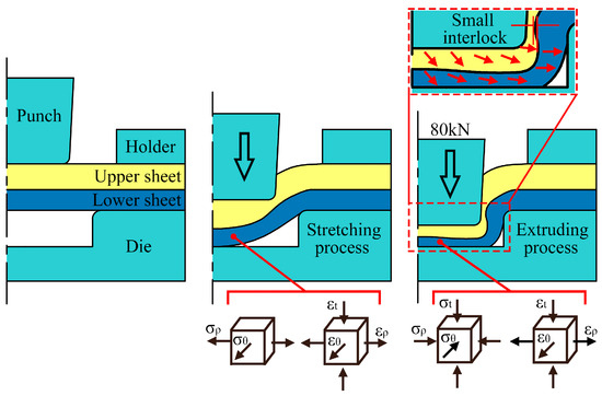
Figure 1.
Mechanical analysis of conventional mechanical clinching process.
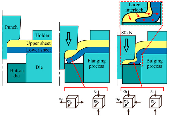
Figure 2.
Mechanical analysis of center-punching mechanical clinching process.
2.2. Principle of CPMC
A schematic diagram of the center punching clinching process is presented in Figure 3. This process utilizes an upper mold (a combination of a punch and a holder) and a lower mold (a combination of a die and a button die). During the experiment, the conversion between punching and clinching functions is achieved through the movement of the slider. The process flow is divided into the following four stages: (a) The slider is adjusted to keep the upper surface of the punching die flush with that of the die, forming a punching die assembly. After the stacked sheets (aluminum sheet on top and steel sheet at the bottom) have been positioned by the lower mold, the upper mold presses down to ensure that the blank holder clamps the two sheets tightly, preventing displacement of the sheets during the connection process. (b) The upper mold continues pressing down until the punching is complete. The generated scrap is discharged through the central through-hole inside the punching die, and then the upper mold pauses. (c) The slider is moved (in actual experiments, the downward pressure of the punch is transmitted to the slider; the program is set to require the punch to return 1–2 mm, and the slider is pulled when there is no pressure). The punching die descends to a specified position and forms a button die assembly. (d) The upper mold presses down for the second time and stops moving when the loading force of the upper mold reaches a preset value. During this process, neck thickness forms at the joint to achieve geometric interlocking, completing the clinching procedure. The morphology of the obtained joint is shown in Figure 4.
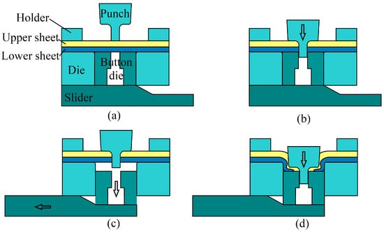
Figure 3.
Schematic of center-punching mechanical clinching process.
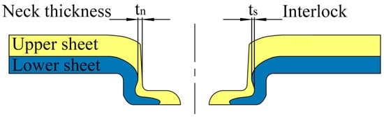
Figure 4.
Clinched joint shape.
3. Finite Element Simulation of CPMC
3.1. Establishment of the Finite Element Model
Based on the Deform software V11.0, a finite element model for center-punching mechanical clinching was established. To improve the calculation efficiency of the simulation, the simulation process began after the punching was complete. Considering that the mold and connection process of the center-punching mechanical clinching technology possess central symmetry, a 2D axisymmetric model was adopted. The 2D axisymmetric model is shown in Figure 5, where A represents the punch radius, B represents the punch draft angle, C represents the punch filet, D represents the die depth, and E represents the die radius.
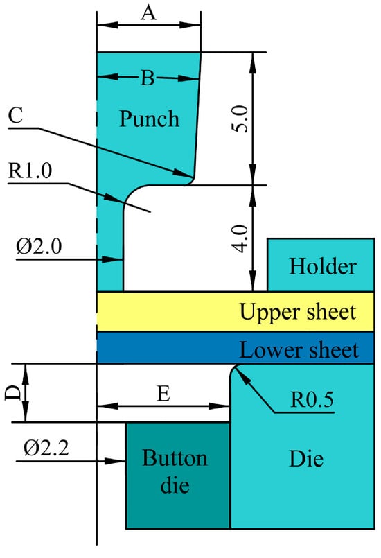
Figure 5.
A two-dimensional axisymmetric geometric model.
In our experiments, 1.5 mm thick AL5052 aluminum alloy and 1.2 mm thick DP980 high-strength steel were selected as the clinched sheet materials. The mechanical property parameters of the materials, as determined via uniaxial tensile tests, are shown in Table 1. The uniaxial tensile tests were conducted according to the international standard ISO 6892-1 [17] using a 100 kN InspektTable100 electronic universal testing machine (Manufacturer: Hegewald & Peschke in Nossen, Germany). The tensile speed was set to 2 mm/min. Each set of specimens was tested three times.

Table 1.
Mechanical properties of materials AL5052 and DP980.
The punch, holder, button die, and die were set as rigid bodies; the upper and lower sheets were set as elastoplastic bodies. Quadrilateral elements were used for mesh division: there were 2000 mesh elements for the upper AL5052 aluminum alloy sheet and 1500 for the lower DP980 high-strength steel sheet. The default size ratio of the mesh was three, and the finite element mesh division is shown in Figure 6. In the initial stages of the study, the step size was set to 0.02 mm. In the later stages, when plastic deformation became more pronounced, the step size was reduced to 0.005 mm. To prevent severe mesh distortion or degeneration when the deformation reached a certain threshold, which may have reduced the accuracy of subsequent calculations or even caused non-convergence, the deformed body needed to be remeshed. In this study, the maximum increment for the remeshing process (e.g., the punch stroke) was set to 0.1 mm. The friction coefficient between steel and steel was set to 0.12, and that of steel and aluminum was set to 0.28 [18]. The holding force was 400 N.
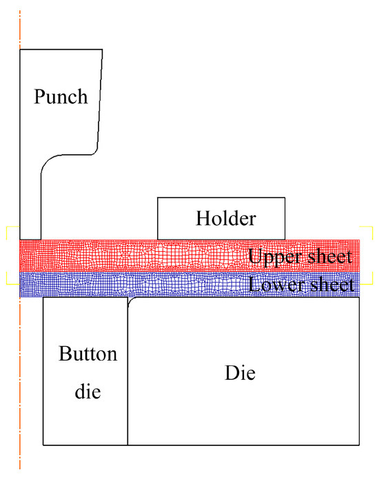
Figure 6.
Meshing of center-punching mechanical clinching.
3.2. Simulation and Analysis of CPMC
We performed a finite element simulation of the center-punching mechanical clinching, as shown in Figure 7. The fracture damage criterion of Deform was adopted [19,20], and the material fracture parameters were redeveloped based on the relevant literature. In the early stage of punching (as shown in Figure 7a), the aluminum sheet is extruded by the punch and undergoes significant plastic deformation, while the steel sheet shows very little plastic deformation due to its high strength. In the middle stage (as shown in Figure 7b), the punch continues to extrude the aluminum sheet, resulting in material thinning in the bottom area of the aluminum sheet. The aluminum material flows laterally, causing thickening in the sidewall area and forming a tiny gap between the aluminum sheet and the steel sheet. At this point, the steel sheet is about to deform. In the late stage of punching (as shown in Figure 7c), the aluminum sheet in the punching area is separated. Meanwhile, the punch and the cutting edge of the die work together to perform plastic shearing on the steel sheet, and the sheet’s thickness remains basically unchanged. Finally (as shown in Figure 7d), the punch continues to press down, the lower sheet is sheared and separated, and the punch pushes the separated material into the die hole, thus completing the punching process.
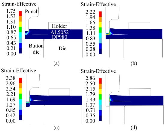
Figure 7.
Equivalent strain change for punching process.
The variation in equivalent strain during the clinching process is shown in Figure 8. Initially, as illustrated in Figure 8a, due to the filet structure at the punch connection, the upper aluminum sheet undergoes slight plastic deformation under extrusion. When the punch moves downward as presented in Figure 8b, the AL5052 aluminum alloy sheet exhibits significant plastic deformation in the punch filet area, with its thickness drastically reducing in this region; meanwhile, the lower DP980 steel sheet begins to contact the bottom surface of the lower die, while the steel sheet in the die cavity enters a deformation stage dominated by flanging deformation; no obvious change in thickness is observed at this time. As shown in Figure 8c, the joint enters the large deformation stage: the neck and the inner edge of the bottom of the AL5052 aluminum alloy sheet generate large equivalent strains, the neck undergoes deep drawing and thinning deformation, and the metal at the bottom fills the expanded area of the steel sheet; the bottom hole diameter of the DP980 steel sheet expands and its edge thins, with the sidewall thickness showing a gradually thinning trend. Figure 8d displays the equivalent strain field when the joint clinching is completed, where an obvious interlocking zone is formed at the bottom of the DP980 steel sheet, which forms an effective connective structure with the convex aluminum alloy sheet.
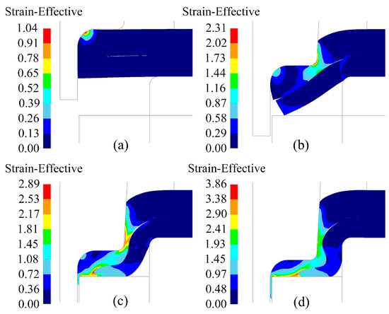
Figure 8.
Equivalent strain change for the mechanical clinching process.
4. Optimization of Mold Geometric Parameters
The geometric parameters of the mold in the center-punching mechanical clinching process affect the forming quality of the joint, and there are interactions between these parameters. Therefore, the orthogonal experimental design method is adopted to optimize the mold geometric parameters, with the goal of obtaining a reasonable joint neck thickness and interlocking amount.
Based on stamping process principles and the two-sheet stacked punching experiment, it is determined that a punching diameter of 2 mm is appropriate. Other mold geometric parameters, namely the punch radius (A), punch draft angle (B), punch filet radius (C), die depth (D), and die radius (E), are selected as the optimization objects for the orthogonal experimental design. In accordance with the experimental requirements, five different level values are chosen for each factor to ensure adequate coverage. The designed factor-level table is shown in Table 2. Through the experimental combinations of different factor levels, the joint neck thickness (Tn) and interlock amount (Ts) can be successfully optimized.
Table 2.
Factor-level table.
The orthogonal array L25(56) was selected for the experimental design and 25 simulation tests were conducted, respectively, to obtain the joint performance data under each set of test conditions. The test schemes and test results are shown in Table 3, where each row represents a combination of test conditions. Figure 9 shows the forming cross-sections of three typical joints: those with good, moderate, and nonexistent interlocking.
Table 3.
Test program and results.
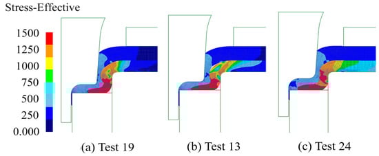
Figure 9.
Formed section of a typical joint: (a) good interlocking; (b) moderate interlocking; (c) no interlocking.
To analyze the degree of influence of mold geometric parameters on the two indicators of joint neck thickness (Tn) and interlock value (Ts), the comprehensive balance method was adopted. It involves analyzing each test indicator independently as a single indicator, then conducting a comprehensive balance based on the analysis results, followed by selecting the optimal reasonable target values. This method was applied to perform a range analysis of the orthogonal test results presented in Table 3; the results can be found in Table 4. The influence curves of geometric parameters are presented in Figure 10. The figure shows that the die depth has a relatively significant impact on the neck thickness, while the punch filet radius has a relatively significant impact on the interlock value. Considering both the neck thickness and interlock value indicators comprehensively, the optimal scheme is determined to be A4B1C2D4E3, which corresponds to a punch radius of 3.9 mm, a punch draft angle of 3°, a punch filet radius of 0.4 mm, a die depth of 2.2 mm, and a die radius of 5.1 mm.
Table 4.
Polar analysis of the orthogonal test.
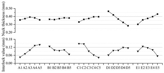
Figure 10.
Indicator factor impact curves.
5. Center-Punching Mechanical Clinching Experiment
5.1. Design of Experimental Mold
The components of the experimental mold include a sleeve, holder, punch retainer, springs, die retainer, punch, punch die, die, and slider. The material grade of key mold components such as punch and die is P20 mold steel, and the overall structure of the mold is shown in Figure 11. For the experimental sheets, the upper sheet is 1.5 mm thick AL5052 aluminum alloy, and the lower sheet is 1.2 mm thick DP980 high-strength steel. The experiment was conducted using a 135 kN servo-hydraulic clinching machine (Manufacturer: SUZHOU SIMITCH MACHINERY in Suzhou, China) with an upper mold speed of 2 mm/s, 80 kN forming force, and a pressure holding time of 5 s after clinching formation. Based on the optimized results, the geometric parameters of the experimental mold are shown in Figure 12.
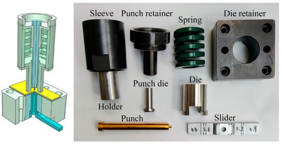
Figure 11.
Center-punching mechanical clinching test mold.
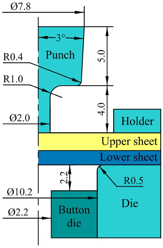
Figure 12.
Geometric parameters of the mold (Unit: mm).
5.2. Experiment on Joint Connection Performance
Cross-sectional diagrams of the experimental and simulated joints are shown in Figure 13, and the geometric parameters of the joints are listed in Table 5. The neck thickness and interlock value of the experimental joint are very close to those of the simulated joint, with errors of 9.4% and 8.9%, respectively.
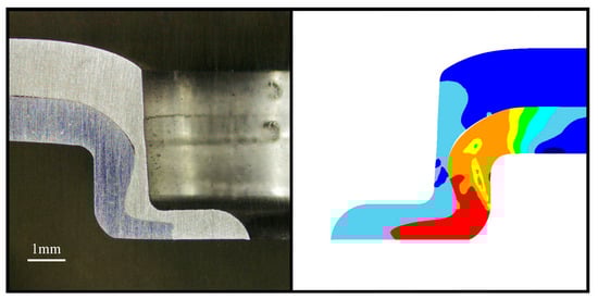
Figure 13.
Experimental and simulated joint cross-sections.
Table 5.
The geometrical parameters of the joints.
Pull-out and tensile shear tests were conducted on the joints using an InspektTable100 tensile testing machine (Manufacturer: Hegewald & Peschke in Nossen, Germany). The joint specimens used are shown in Figure 14. The testing speed for both the pull-out and tensile shear tests was set to 2 mm/min. To ensure the stability and repeatability of data, each joint was subjected to each test in triplicate.
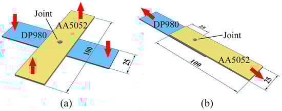
Figure 14.
Test specimens: (a) Pull-out specimen; (b) tensile shear specimen.
Figure 15 shows the load–displacement curves of the pull-out and tensile shear tests for each group of joints. As the displacement increased, the pull-out and tensile shear loads gradually increased. Once the joints reached their maximum tensile strength and shear strength, the joints underwent fracture failure, and the curves dropped rapidly to 0. The pull-out force and tensile shear force data of each group of joints are shown in Table 6. The results indicate that the maximum pull-out force was 1152 N and the maximum tensile shear force was 2256 N. When the traditional clinching process was used to connect AL6061/DP590, the maximum pull-out and tensile shear force of the obtained joints were 2760 N and 1575 N, respectively [3], slightly higher than the joint strength reported in this study. This is because the material strength of AL6061 is slightly greater than that of AL5052. The experiment proves that the center-punching mechanical clinching process is feasible.
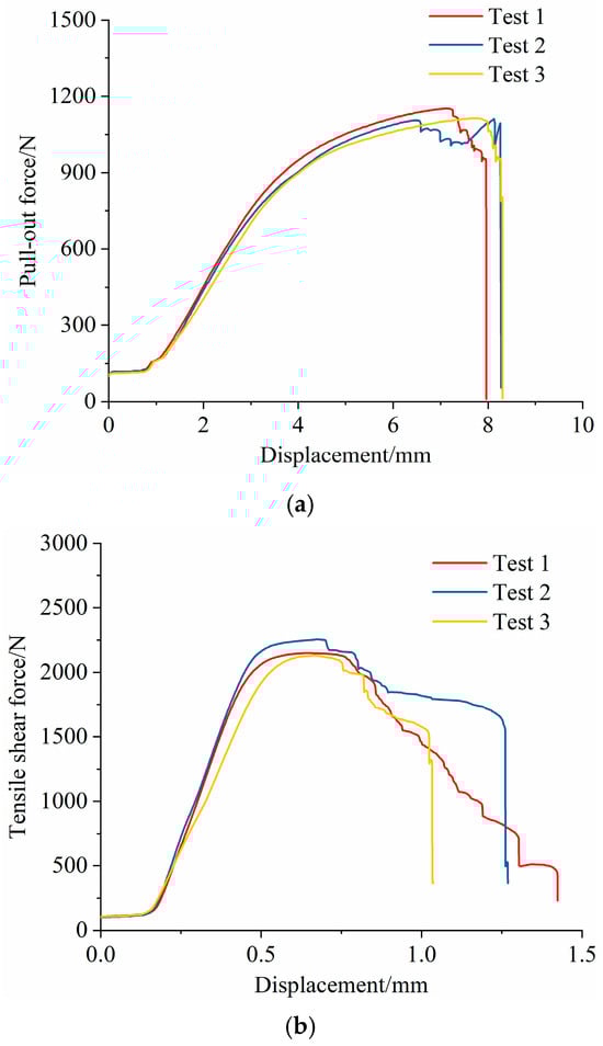
Figure 15.
Force–displacement curves of joints: (a) pull-out test; (b) tensile shear test.
Table 6.
The pull-out force and tensile shear force of the joints.
The failure modes of the joints after the pull-out and tensile shear tests are shown in Figure 16 and Figure 17. In both cases, the failure mode took the form of a neck fracture. Finite element simulation results indicate that stress concentration in the joint primarily occurs at the neck. As pull-out and tensile shear displacements increase, tearing is initiated in this area and continues to progress. The stresses at the bottom of the aluminum and steel plates remained relatively low, suggesting that the center-punching did not affect the strength of the joint. Moreover, the punched area did not exhibit significant deformation during the failure process.
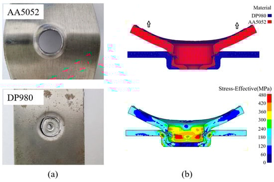
Figure 16.
Clinched joints in pull-out testing: (a) experiment; (b) simulation.
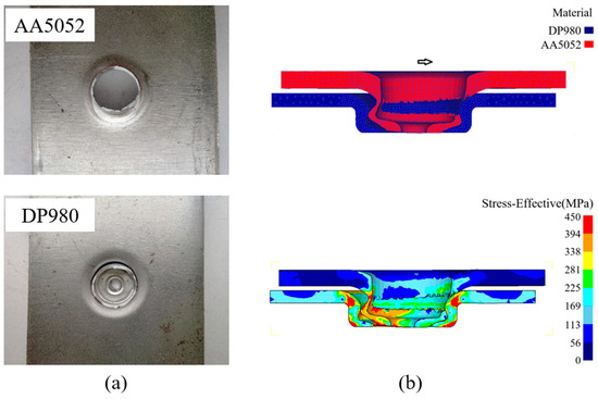
Figure 17.
Clinched joints in tensile shear testing: (a) experiment; (b) simulation.
6. Conclusions
This study suggests that a mechanical center-punching process can be used to clinch high-strength steel (with tensile strength exceeding 1 GPa) and thin aluminum alloy sheets. Through numerical simulations, orthogonal optimization, and mechanical experiments, the joining mechanism of center-punching mechanical clinching and the optimization of clinching mold geometric parameters were systematically studied. The principal findings are as follows:
- (1)
- Finite element simulation technology was adopted in combination with the orthogonal experimental design method to optimize and select reasonable mold geometric parameters, specifically a punch radius of 3.9 mm, a punch draft angle of 3°, a punch filet radius of 0.4 mm, a die depth of 2.2 mm, and a die radius of 5.1 mm. Orthogonal test analysis shows that the die depth has a relatively significant impact on the joint neck thickness, while the punch filet radius influences the interlocking of the joint.
- (2)
- The results of the established 2D axisymmetric finite element simulation are compared with the experimental measurement values. The deviations of the neck thickness and the interlock value are 9.4% and 8.9%, respectively, confirming that the finite element simulation is relatively accurate.
- (3)
- Through the joint connection performance experiment, the average pull-out force and tensile shear force of the joint were determined to be 1124 N and 2179 N, respectively, which verifies the feasibility of the process described in this study.
- (4)
- There is no analysis of joint micromorphology and fatigue analyses in this article, which will be studied later.
Author Contributions
P.Q.: Writing—Review and Editing; Formal Analysis; Methodology. X.L.: Writing—Original Draft; Formal Analysis. B.D.: Software; Formal Analysis; Visualization. H.X.: Project Administration; Funding Acquisition, Methodology. C.Y.: Investigation; Data Curation; Methodology. All authors have read and agreed to the published version of the manuscript.
Funding
This work was supported by the Project of the Central Government Guiding Local Science and Technology Development [Grant number: 226Z1809G].
Data Availability Statement
The data presented in this study are available upon request from the corresponding author. The data are not publicly available due to privacy.
Acknowledgments
The authors would like to thank the Nation Engineering Research Center for Equipment and Technology of Cold Rolled Strip in Yanshan University for their assistance in testing the clinching joint.
Conflicts of Interest
The authors declare no conflicts of interest.
References
- Shi, C.; Yi, R.; Chen, C.; Chen, C.; Peng, H.; Ran, X.; Zhao, S. Forming mechanism of the repairing process on clinched joint. J. Manuf. Process. 2020, 50, 329–335. [Google Scholar] [CrossRef]
- Han, D.; Hu, C. Clinching of Carbon Fiber-Reinforced Composite and Aluminum Alloy. Metals 2024, 14, 681. [Google Scholar] [CrossRef]
- Li, Q.; Xu, C.; Gao, S.; Han, X.; Zhao, Q.; Gu, D.; Ma, F. Clinching Test for High Strength Steel-Aluminum Alloy Dissimilar Material Sheets. J. Mech. Eng. 2021, 32, 1861–1867. [Google Scholar] [CrossRef]
- Meilinger, Á.; Kovács, P.Z.; Lukács, J. High-Cycle Fatigue Characteristics of Aluminum/Steel Clinched and Resistance-Spot-Welded Joints Based on Failure Modes. Metals 2024, 14, 1375. [Google Scholar] [CrossRef]
- Ouyang, X.; Chen, C. Research on the joining of aluminum alloy and high-strength steel by dieless clinched-adhesive processes. J. Mater. Process. Technol. 2023, 24, 5526–5540. [Google Scholar] [CrossRef]
- Chen, C.; Ran, X.; Pan, Q.; Pan, Q.; Zhan, H.; Yi, R.; Han, X. Research on the mechanical properties of repaired clinched joints with different forces. J. Thin Walled Struct. 2020, 152, 106752. [Google Scholar] [CrossRef]
- Lee, C.; Lee, J.; Ryu, H.; Lee, K.; Kim, B.; Ko, D. Design of hole-clinching process for joining of dissimilar materials—Al6061-T4 alloy with DP780 steel, hot-pressed 22MnB5 steel, and carbon fiber reinforced plastic. J. Mater. Process. Technol. 2014, 214, 2169–2178. [Google Scholar] [CrossRef]
- Han, S.; Wang, Z.; Wang, Z.; Li, Y. Heat-assisted hole-clinching process for joining magnesium alloy and ultra-high-strength steel. J. Adv. Manuf. Technol. 2021, 115, 551–561. [Google Scholar] [CrossRef]
- Abe, Y.; Mori, K. Mechanical Clinching Process with Preforming of Lower Sheet for Joining Aluminum and Ultra-High Strength Steel Sheets. Q. J. Jpn. Weld. Soc. 2020, 38, 89s–92s. [Google Scholar] [CrossRef]
- Fu, L.; Zhang, S.; Qiu, P.; Xiao, H.; Deng, B.; Lu, X. Optimization of Clinching Joint Process with Preforming between Ul-tra-High-Strength Steel and Aluminum Alloy Sheets. Metals 2024, 14, 767. [Google Scholar] [CrossRef]
- Zhuang, W.; Zhao, W.; Xie, D.; Li, B. Research on Hot Riveting Quenching Clinching of the High Strength Steel 22MnB5 and Aluminum Alloy 7050. J. Mech. Eng. 2017, 53, 106–112. [Google Scholar] [CrossRef]
- Roux, E.; Bouchard, P.O. Kriging metamodel global optimization of clinching joining processes accounting for ductile damage. J. Mater. Process. Technol. 2013, 213, 1038–1047. [Google Scholar] [CrossRef]
- Chen, C.; Zhao, S.; Han, X.; Cui, M.; Fan, S. Optimization of a reshaping rivet to reduce the protrusion height and increase the strength of clinched joints. J. Mater. Process. Technol. 2016, 234, 1–9. [Google Scholar] [CrossRef]
- Oudjene, M.; Ben-Ayed, L.; Delameziere, A.; Batoz, J. Shape optimization of clinching tools using the re-sponse surface methodology with Moving Least-Square approximation. J. Mater. Process. Technol. 2009, 209, 289–296. [Google Scholar] [CrossRef]
- Lambiase, F.; Di, I.A. Optimization of the Clinching Tools by Means of Integrated FE Modeling and Artificial Intelligence Techniques. J. Procedia CIRP 2013, 12, 163–168. [Google Scholar] [CrossRef]
- Abe, Y.; Mori, K.; Kato, T. Joining of high strength steel and aluminum alloy sheets by mechanical clinching with dies for control of metal flow. J. Mater. Process. Technol. 2012, 212, 884–889. [Google Scholar] [CrossRef]
- ISO 6892-1; Metallic Materials—Tensile Testing—Part 1: Method of Test at Room Temperature. ISO (International Organization for Standardization): Geneva, Switzerland, 2019.
- Li, Q.; Xu, C.; Gao, S.; Ma, F.; Zhao, Q.; Han, X.; Wang, B. Numerical simulation of clinching for dissimilar thin-sheets and influence law of process parameters. J. Plast. Eng. 2021, 28, 113–121. [Google Scholar] [CrossRef]
- Ma, C.; Zhang, D.; Gong, Z.; LIU, X.; SONG, H.; LI, D. Study on ductile fracture criterion parameters of high strength duplex steel plate. J. Mech. Strength 2023, 45, 1474–1482. [Google Scholar] [CrossRef]
- Yu, H.; Wang, Y. Bulging simulation of ductile fracture of 5052 aluminum alloy. J. Nonferrous Met. 2015, 25, 2975–2981. [Google Scholar] [CrossRef]


Disclaimer/Publisher’s Note: The statements, opinions and data contained in all publications are solely those of the individual author(s) and contributor(s) and not of MDPI and/or the editor(s). MDPI and/or the editor(s) disclaim responsibility for any injury to people or property resulting from any ideas, methods, instructions or products referred to in the content. |
© 2025 by the authors. Licensee MDPI, Basel, Switzerland. This article is an open access article distributed under the terms and conditions of the Creative Commons Attribution (CC BY) license (https://creativecommons.org/licenses/by/4.0/).