2. The Prior Crack Population
Almost without exception, our engineering metals are processed originally by melting and casting [
1]. The casting process usually involves the pouring of the metal into a mold to form a billet or a slab. The free fall of the metal in the air has been identified as a critical event, damaging the liquid [
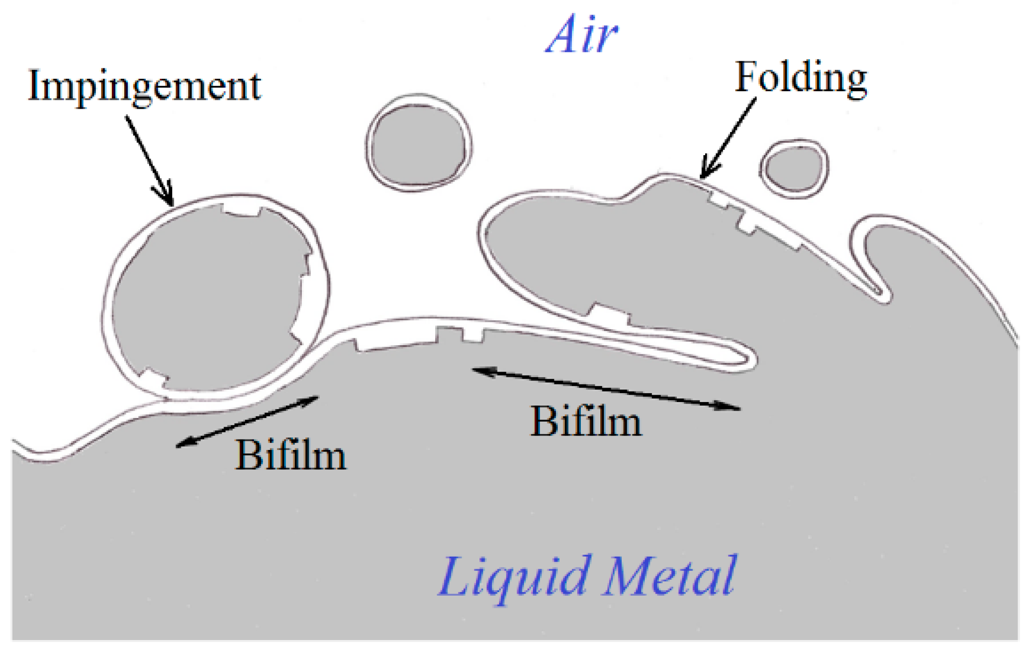
2]. The turbulence creates the opportunity for the liquid to fold over on itself or suffer from the impinging of drops and splashes. Such events bring together the dry upper surfaces of the surface oxide with the liquid. Because this is a ‘dry’ surface consisting of an oxide ceramic such as alumina, the folds and the impingements cannot bond, but form cracks in the liquid. These double oxide films have been called ‘bifilms’ (
Figure 1).
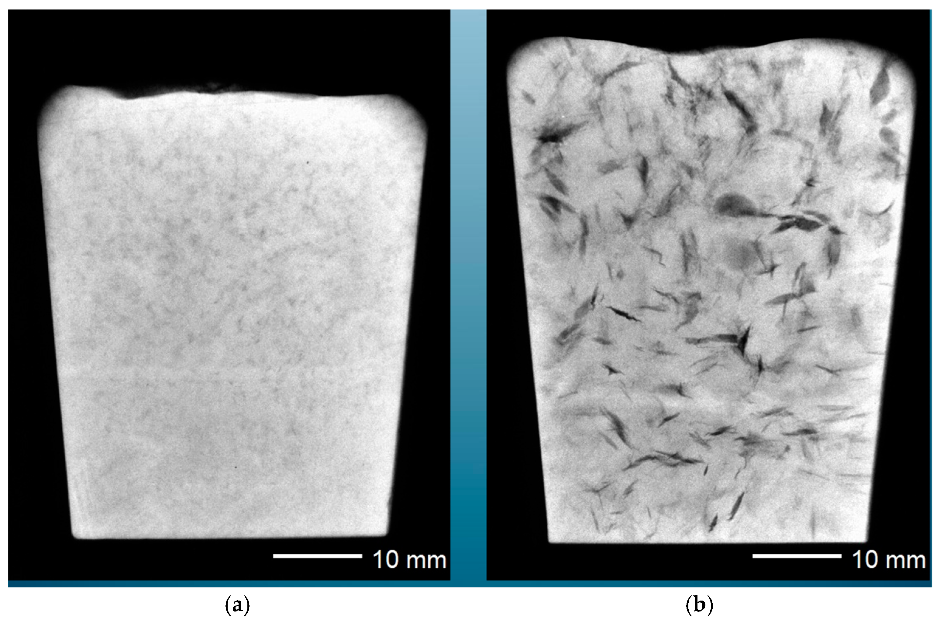
Initially, the bifilms are suspended in the liquid metal, and the initial violence of the turbulence during pouring ravels the bifilms into crumpled, convoluted forms. In this compact condition, they are comparatively harmless. However, gas in the solution can diffuse into the bifilm, inflating it and so unfurling the complex multiple folds to create something like an engineering crack. This effect is demonstrated in
Figure 2, in which the left-hand casting shows compact bifilms, whereas the second otherwise identical casting is subjected to a reduced pressure, inflating and unfurling the bifilms and leading to serious cracks [
3].
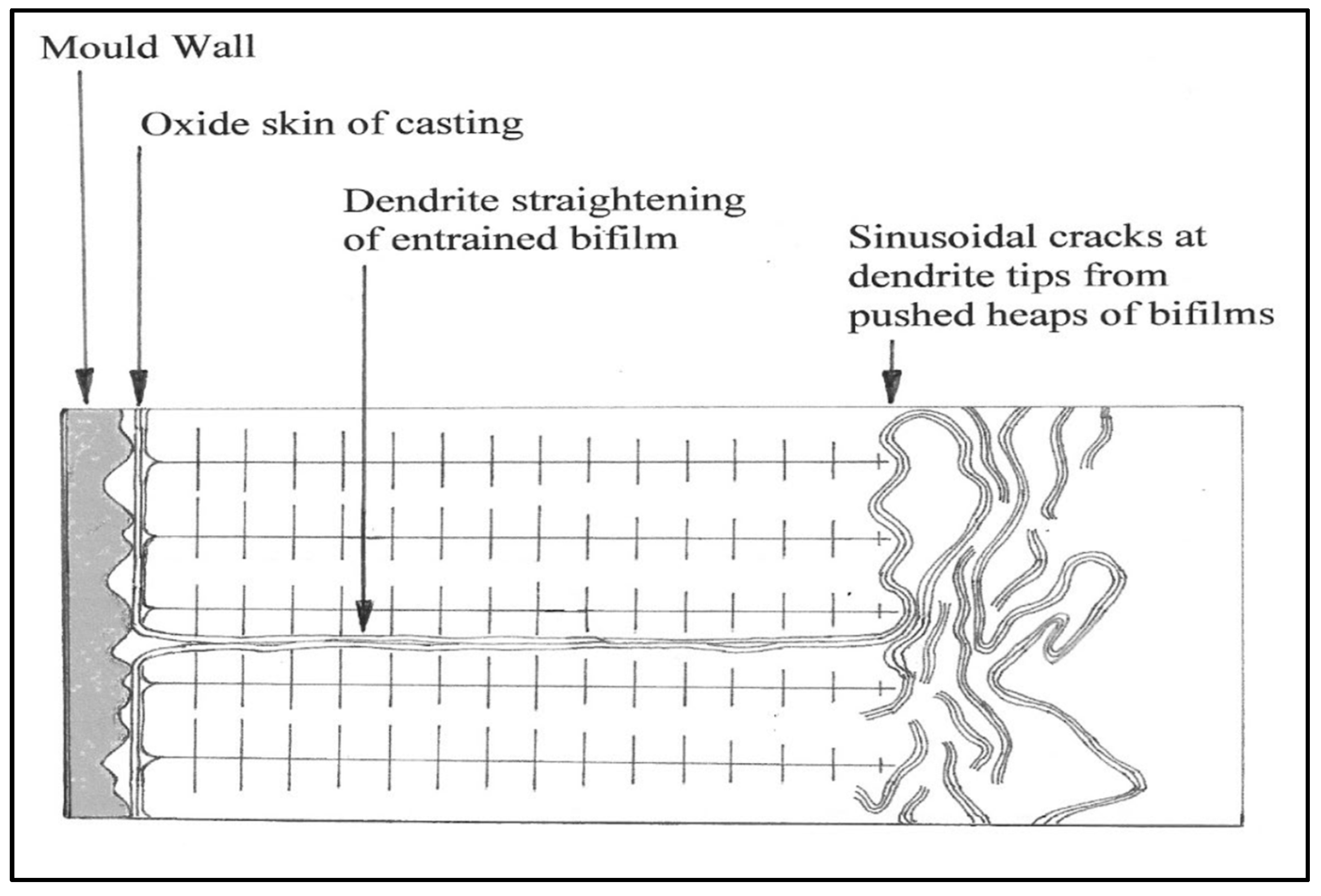
Even without gas in the solution, bifilms can be straightened out to become serious cracks by dendrite growth. As freezing progresses, they are ‘pushed’ by the advancing dendrites and thereby segregated. Those that are pushed sideways by the dendrites and aligned along the dendrite direction tend to finish as transverse bifilms in the as-cast grains, and these are mainly concentrated in the columnar grains near the walls of the ingot mold (
Figure 3). Those that are pushed forward, ahead of the dendrites, tend to finish trapped between impinging grains in the central regions of an ingot, giving rise to a population of intergranular bifilm cracks (
Figure 4). Interestingly, the chemical segregation around the transgranular and intergranular boundaries will be different, although the difference may tend to diffuse away with time and temperature.
The bifilms survive the freezing of the metal, so that they remain present in the solidified ingot. The stability of the stable-oxide-to-stable-oxide interface means that the bifilm cracks tend to withstand significant plastic working, and so often remain to characterize the final component, such as the forged undercarriage for an aircraft, rolled plate for a pressure vessel or pipeline, or fine-drawn wire.
During the progress of plastic working, the structure will recrystallize, with grain boundaries (gbs) migrating. Upon the arrival of a gb at a bifilm, the gb will be unable to cross the ‘air gap’ between the two films, and so will become pinned. In effect, the bifilm will become the gb. Steels that solidify to austenite are a good example. Many gbs formed in the liquid state, plus those formed at high temperature while gbs are still mobile, will be expected to contain bifilms, so that, on further cooling and transformation to ferrite, the prior austenite grain boundaries (PAGBs) are naturally immovable, explaining the curiosity of their survival in lower temperature ferritic structures. If steels were cast better, PAGBs may not exist.
It is noteworthy that some stress corrosion cracking (SCC) examples exhibit intergranular cracks and others exhibit transgranular cracks. Interestingly, the large steel plates for boiling water reactors are sufficiently large, utilizing much of the ingot, and therefore include both varieties of SCC cracks.
In addition, during plastic working, bifilms will become aligned with the working direction, giving rise to the development of the familiar wood-grain texture. It is salutary to consider that the development of the texture was a key raison d’etre of the forging industry. It was known that cracks could propagate directly through a casting but would not cross a forging. Any crack would be diverted along the axis of the forging, following the aligned population of bifilm cracks, thereby avoiding a transverse fracture of the forging. Forgings, therefore, gain reliability not only because of the closure of pores and cracks, but also because of the important action of the texture arising from the alignment of bifilms [
3].
In passing, it is also salutary to reflect that, if the original casting had been made with good technology, avoiding turbulence and achieving good soundness, no bifilms would have been present in the metal; in this case, crack initiation and propagation conditions would have been identical for both casting and forging. Effectively, the forging industry would only have been a shaping industry, not an industry also offering improved toughness.
3. Precipitation During Solidification
Cao was the first to identify the precipitation of α-Fe and β-Fe intermetallics on bifilms in Al-Si alloys [
4]. For those precipitates that grew as platelets, such as β-Fe, the bifilms were straightened by the growth of the intermetallic, and the originating substrate bifilm was identified as the crack down its center if the phase formed on both outer wetted interfaces of the bifilm. If the precipitate formed only on one side of the bifilm, the phase would have appeared to have decohered from the matrix.
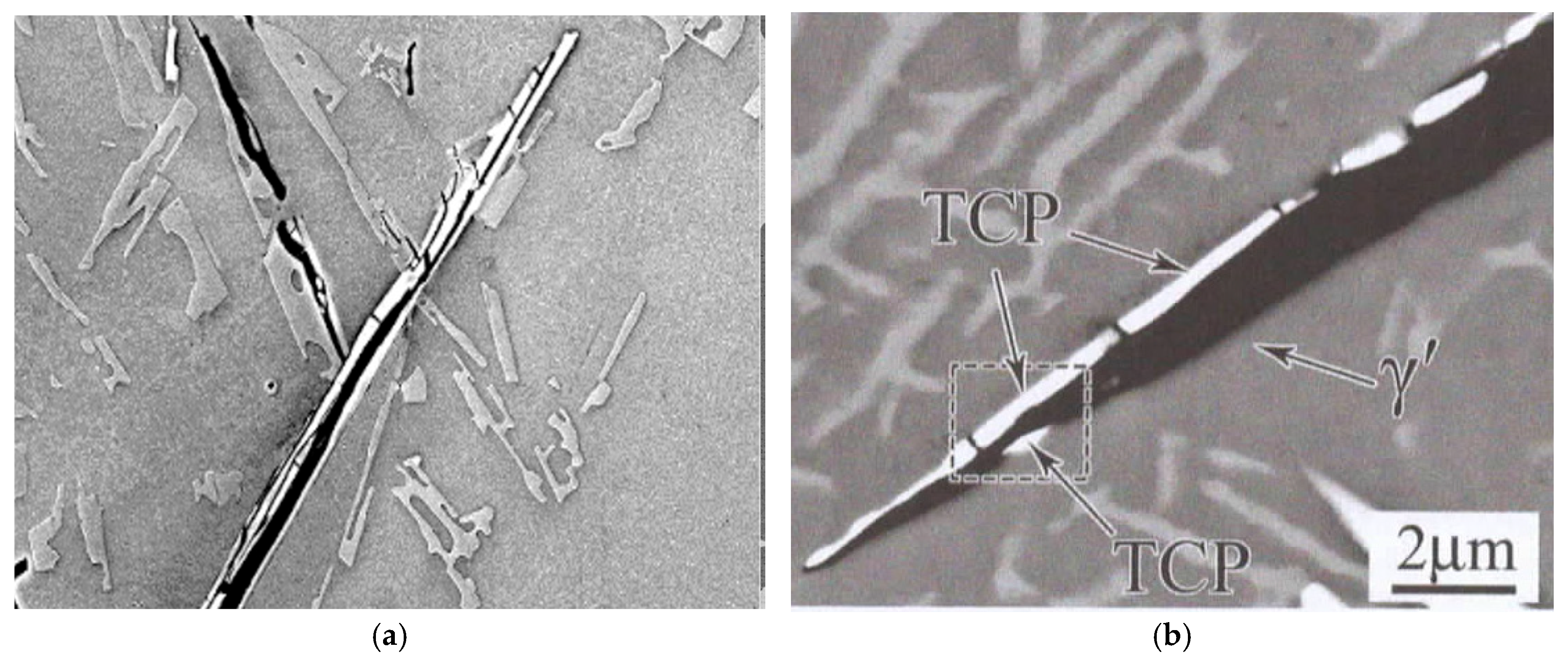
Immediately after casting, the bifilm always arrives in the mold in a compact, convoluted form because of the intense turbulence of the pour. If frozen into the metal as a small defect, it would be only slightly damaging. However, if the bifilm were straightened by the growth of a precipitate having a planar morphology, as is observed with the formation of β-Fe intermetallics, the bifilm population could become a population of planar cracks, opened to their maximum extent (
Figure 5a). The mechanical properties of the metal are thereby reduced, as is also observed during slow solidification, which gives the bifilms time to unfold, extending to maximize their role as cracks. β-Fe grows with a plate morphology because of its monoclinic crystal form.
Conversely, for α-Fe, the high symmetry of its cubic lattice permits it to grow in any direction, so that, when precipitating and growing on the initially compact bifilm, it simply wraps around the bifilm, sealing its compact morphology into place. The Al-Si alloys are well known to benefit from the relatively small addition of Mn to encourage α-Fe to form instead of β-Fe. Fe is probably the most detrimental impurity in Al alloys because (i) a small Fe contribution of one Fe atom in the composition of Al5SiFe increases the bulk of the crystal by five Al atoms, and (ii) it straightens compact bifilms into ‘engineering’ cracks.
A further detail of the morphology of the straightened films is of central interest. In the surface turbulence when bifilms are being created, during the impingement of two oxide films, it is certain that one film will be larger than the other. (This is a kind of logical tautology!) The consequence is that the larger film will necessarily develop rucks and creases as it accommodates itself to settling against the smaller film. As a result, the growth of the β-Fe on the side of the smaller film is uninterrupted, becoming an extensive continuous crystal. However, on the originally larger film, the growth of the β-Fe crystal is continuously interrupted by transverse folds, which appear as transverse cracks. This is clearly demonstrated in
Figure 5a. This detail of the structure, with the central crack with transverse cracks on only one side, and a continuous crystal on the other, appears to be a definitive and unique morphology, confirming the presence of a bifilm. The distinctive morphology is observed in a topologically close-packed (TCP) phase in a Ni superalloy in
Figure 5b, confirming the presence of bifilms in Ni superalloys [
1].
It is conventional to explain the formation of second phases and intermetallics on such interfaces as those of bifilms by the traditional logic of matching lattice spacings, reducing the interfacial energy sufficient to favor nucleation and growth. However, Fan [
5] has gone further, demonstrating that, where the oxide film density is high, as is to be expected in liquid metals which have been poured, nucleation on oxides can be expected even if the lattice spacing is unfavorable. This occurs simply because of the overwhelming number of oxide surfaces available—other favorable nuclei may be present, but their relatively small numbers cause them to be irrelevant.
We conclude, therefore, that, in the liquid state, in practice, second phases and intermetallics form exclusively on bifilms. (We shall see there are good reasons why a similar exclusivity (or near exclusivity) of precipitation on bifilms occurs in the solid state, but for quite different reasons).
In the meantime, we shall divert to examine the exclusivity conclusion, which has interesting implications. It predicts that, in the absence of bifilms, the precipitation of second phases and intermetallics will not form. Thus, the elements that constitute these compounds would necessarily remain in solution, possibly as a supersaturated solution. Al-Si alloys would, therefore, not precipitate Si as a primary phase, but it would be possible to grow it continuously (having formed from the presence of relatively few, rare, tolerably favorable nuclei probably in supercooled pockets of the liquid adjacent mold walls) as a coupled eutectic—it would therefore be automatically ‘modified’ without the action of Na or Sr [
3]. Virgin Al-Si alloys directly reduced from the ores, and prior to their fate to start the accumulation of bifilms, confirm the natural, fine, modified structure up to 17 wt.% Si [
6]. Also, in the absence of bifilms, the iron impurity usually present in Al-Si alloys would no longer occur as a deleterious embrittling phase, but would remain in solution, becoming a valuable alloying element, aiding strength and hardness by solid solution strengthening.
4. Precipitation in the Solid State
Precipitation of second phases and intermetallics is traditionally assumed to occur on grain boundaries because of the saving of interfacial energy. However, the formation of a new particle within the matrix lattice is usually accompanied by a volume change and a shape change, which necessarily initiates a plastic zone around the forming particle, which spreads out from the particle as the particle grows. Plastic deformation is a high-energy process and would be expected to outweigh the tiny interfacial energy by orders of magnitude. We can estimate the energy involved in the formation of a particle [
2].
The surface energy saved by precipitation of the particle on a grain boundary is the area a2 of a cubic particle of side ‘a’ multiplied by the energy per unit area of the grain boundary γ, where γ is the surface energy approximately 0.1 N/m = 10−1 erg/m2. Neglecting the surface energy of the particle, the maximum energy saved by formation on the boundary is therefore approximately a2γ = 10−9 erg.
Considering now the strain energy required to form a particle precipitating in a grain boundary or in the matrix (there is little difference between the two locations) of yield strength σy, the force exerted on the matrix by one face of the growing particle is σy·a2. If the matrix is forced away from the growing particle by a growth fraction Δx, the energy required is the force times the linear distance, aΔx, giving the energy σya3Δx. Summing the effects of growth on six sides, the total energy is 6σya3Δx. For a particle of side 10 μm, in a matrix of yield strength 100 MPa, and growing by 1 per cent, the total energy is close to 10−8 erg. This significant underestimate is merely a guide. A shape change would involve additional energy but is not considered here.
The strain energy in our example is, therefore, a minimum of 10 times the surface energy. Thus, the strain energy is the dominant effect controlling the formation of most primary phases and intermetallic compounds in solids.
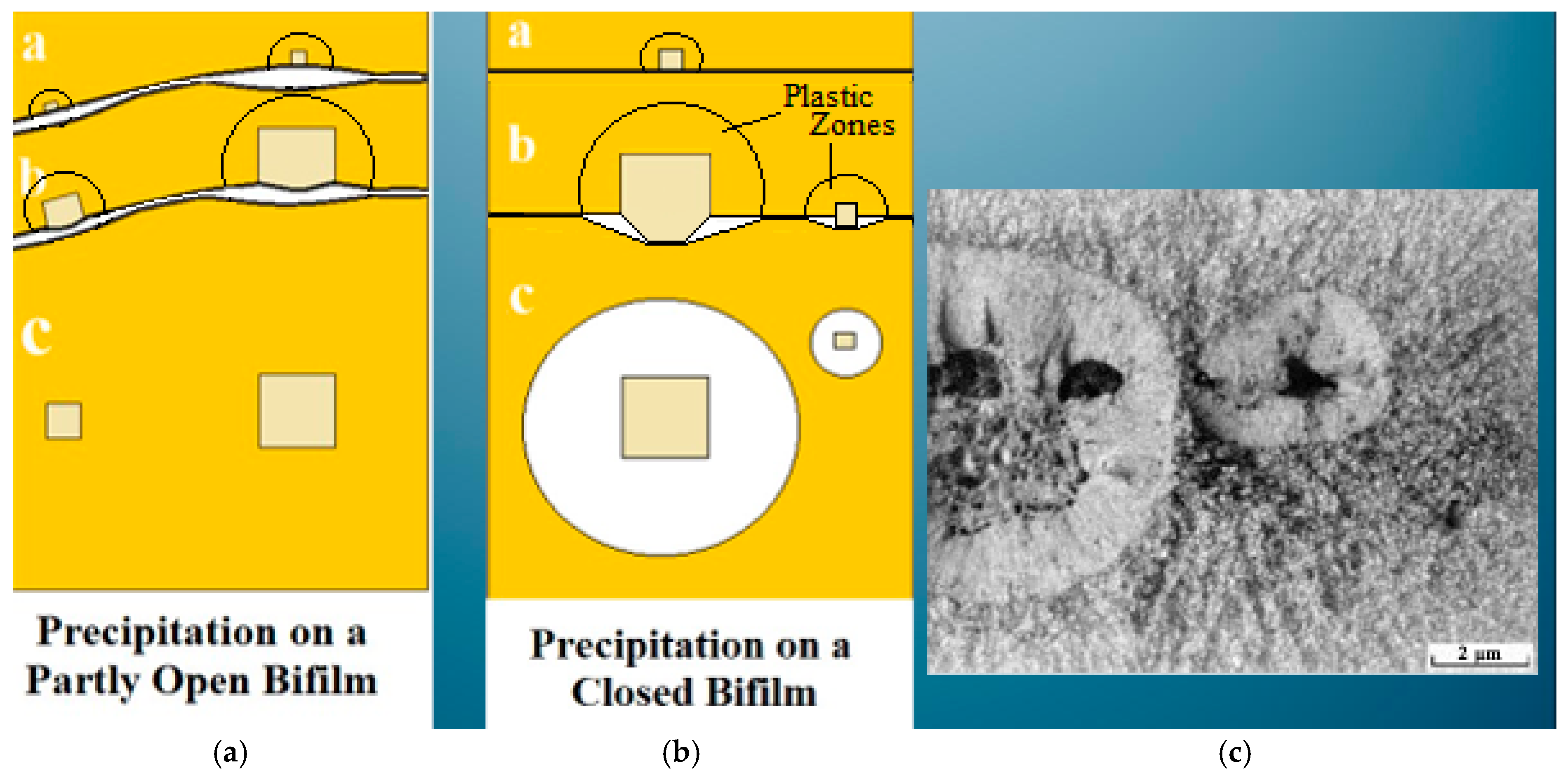
Turning now to the involvement of bifilms. It is to be expected that they could be favored substrates for precipitation, because the growth of the particle into the ‘air gap’ of the bifilm would be so much easier than growth into the matrix. The particle growing on the bifilm and out into the matrix would be forced backwards by the matrix into the bifilm, thereby prizing open the bifilm. The effect would be to spread a significant proportion of the volume and shape changes over a larger area by the elastic accommodation of the bifilm. The deformation of the bifilm is expected to be in the elastic range because its deformation will be small, but extensive. Naturally, the elastic accommodation provided by the bifilm will be orders of magnitude less energy than the plastic deformation of the matrix.
It follows that for those phases that have a high strain of formation, precipitation of most new phases and intermetallics will normally occur only on bifilms, not on grain boundaries, as may be occurring in
Figure 6. Conversely, those that have minimal strain energy of formation and good lattice matching, may therefore form on grain boundaries.
The fact that up to 50 per cent or more grain boundaries can be decorated by precipitates, with the other 50 per cent containing zero precipitates, may be an indication that approximately half of all grain boundaries contain bifilms. If so, it seems we should expect there to be two distinct varieties of grain boundary: those with and those without bifilms. Interestingly, the bifilm densities commonly seen in metals correspond well with the densities of grain boundaries. Thus, the observation of around 50 per cent of boundaries containing precipitates appears to be a reasonable correlation.
Nevertheless, of course, it remains possible that, in relatively rare cases, precipitates of good matching with the matrix, and zero shape change, may have such a low strain energy of formation that the interfacial energies will dominate, favoring formation on clean grain boundaries.
8. Hydrogen Embrittlement
Hydrogen embrittlement (HE) has been reviewed many times over the years, notably by Gibala and Hehemann 1984 [
16] and Chen 2025 [
17]. Chen and colleagues conclude their review with a statement:
“The embrittlement of high-strength engineering alloys in hydrogen-containing environments is a longstanding problem. Much has been done. There is much more to do. Despite some progress, the issue is still largely managed in the industry by using lower-strength, less hydrogen-susceptible alloys, sacrificing efficiencies in design. The dawn of a hydrogen economy completely changes the picture”.
However, despite the urgency that is now upon us, as for SCC, it seems fair to conclude that a clear explanation permitting the development of a solution for HE has not yet emerged from the lengthy history of studies so far.
Considering first the aluminum alloys, an environment of dry hydrogen has no effect, but, the instant that water vapor is introduced into the environment, the water reacts with the aluminum, releasing atomic hydrogen, which diffuses into the metal [
18].
When in the metal, the hydrogen appears to become trapped in sinks. These have been proposed to be inclusions, dislocations, and stress fields. However, there seems to be no doubt that the major traps are bifilms. This is confirmed by an experiment by Toda in which a tensile test of an aluminum alloy was carried out in a vacuum chamber [
19]. On fracture, the pressure in the chamber jumped from the release of hydrogen. The ‘instantaneous’ nature of the release indicates that hydrogen was released from void-type traps, such as cleaved open bifilms, not from supposed traps in the matrix, such as dislocations or stress fields, because the diffusion of hydrogen out of the lattice would have taken time, at least a minute or two, causing a slow rise in the hydrogen pressure after fracture. It would be useful to repeat this experiment with steel.
Additional confirmation that hydrogen diffuses into bifilms where atomic hydrogen precipitates as hydrogen gas is provided in a direct visual form by blistering. Blisters occur on aluminum alloys when subjected to a humid atmosphere at an elevated temperature. They typically occur when heat treating if the heat treatment furnace contains water vapor (
Figure 8). Once again, the reaction of the water releases hydrogen into the metal, where it can accumulate as hydrogen gas in bifilms close to the surface. If the bifilm is sufficiently close to the surface, and if the temperature is sufficiently high to soften the metal, the thin thickness of metal between the bifilm and the surface can be deformed as a balloon, creating the surface blister.
There is some evidence that gases may enter the metal more quickly than would be expected by diffusion by travelling preferentially along bifilms paths. However, this is not yet known for hydrogen, and it is possible that hydrogen may not need such assistance. At a temperature of around 500 °C, the rate of diffusion of hydrogen is approximately 10
−8 m
2/s [
1]. Using the order of magnitude relation giving the distance diffused x = (Dt)
1/2, for a time of 1 s, we obtain a diffusion distance of 0.1 mm. For 100 s, the distance is 1 mm, for 10,000 s (nearly 3 days) the distance is 10 mm.
Even if the hydrogen diffuses preferentially along bifilms, it will be required to diffuse through the solid between bifilms, the distances of which are usually in the range from 0.1 to 1.0 mm, and so it will take time, from 1 s to 1 min for each boundary. The numbers seem reasonable and feasible.
Hydrogen blisters are a clear visual demonstration of the behavior at the surface of a metal, which mirrors the mechanism of hydrogen embrittlement occurring in the interior.
As hydrogen diffuses into the metal, it precipitates as hydrogen gas in the bifilms. As the hydrogen pressure in the bifilms increases, they are gradually forced open. Morrissay observed the increase in volume of porosity by a factor of 18 as charging proceeded [
20]. It is to be expected that expansion occurs first elastically but later plastically, extending the bifilm cracks to cause linking. This is envisaged to become an unstable, runaway process. The opened, pressurized bifilms will tend to shear the ligaments of metal between bifilms, causing the macroscopic ‘fracture’ to proceed rapidly across successive bifilms, perhaps hesitating only briefly at the boundary of each bifilm as the extra load is experienced by the connecting ligament. The final fracture surface characteristically exhibits facets or pseudo-cleavage, which often appears to follow ‘grain boundaries’. The steps surrounding each facet correspond to sheared regions where the rapid stepwise failure shifts levels to the next available bifilm. Transgranular bifilms will tend to create planar facets, often corresponding to a 100 plane of the grain, whereas intergranular bifilms will tend to follow the grain boundaries, resembling curiously curved or conchoidal shapes.
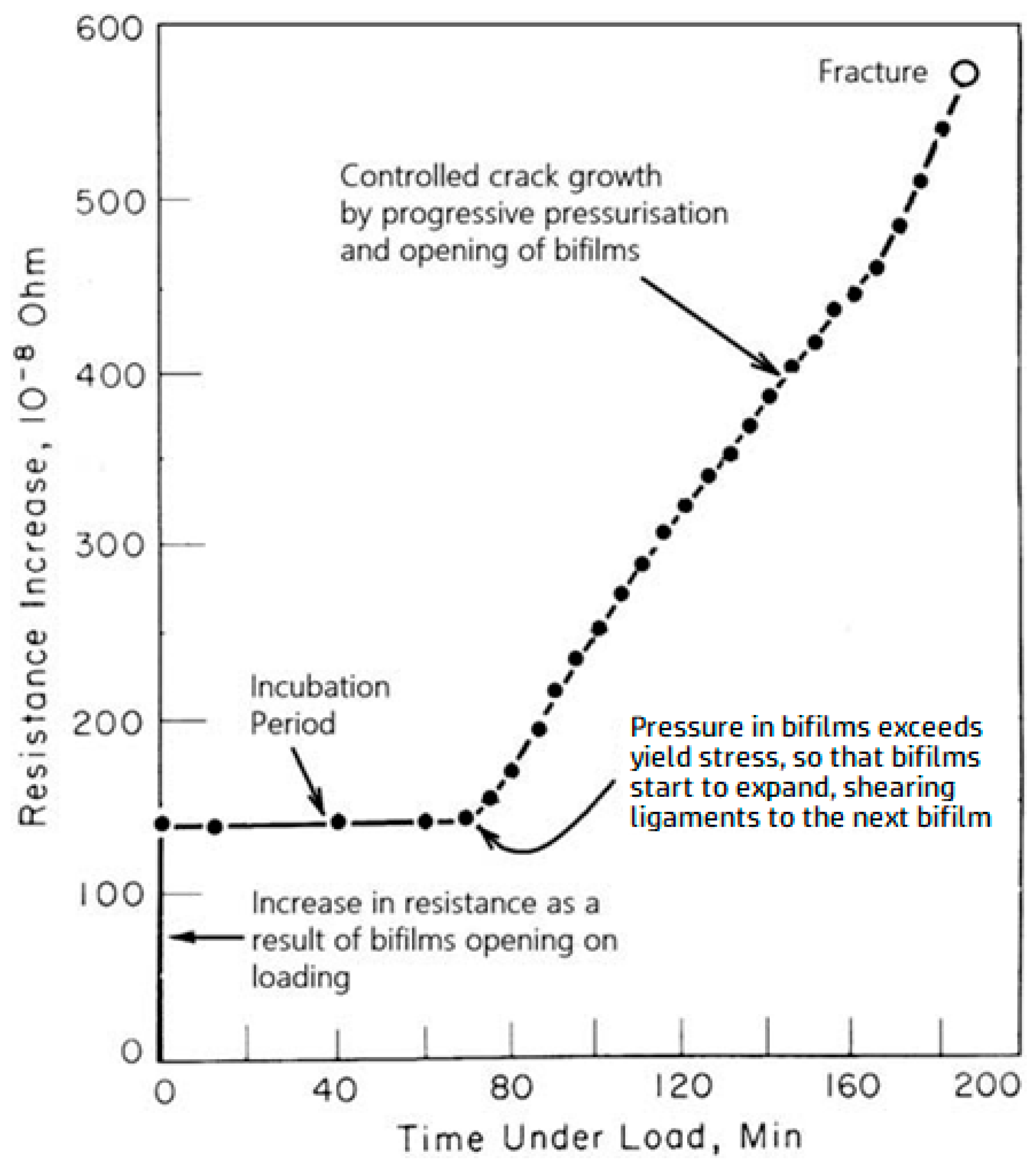
Figure 9 shows the result of a significant experiment involving a notched-steel test piece, electrochemically charged with hydrogen, stressed by a weight. Upon attaching the weight, the bifilms immediately open and may propagate a little, causing an initial jump in electrical resistance. No further propagation occurs while hydrogen continues to diffuse into the bifilms until the hydrogen pressure reaches the yield stress of the metal. At that point, the larger bifilms oriented perpendicular to the stress will tend to be the first to expand, plastically shearing the ligaments which connect to the next randomly aligned bifilm, permitting the crack to incorporate the next bifilm as a region of ‘quasi cleavage’, and so on to further bifilms as gas continues to build and pressurize the additional crack area.
