Abstract
The high-power engine exhaust elbow has a complex construction, which makes it susceptible to casting flaws that could negatively impact its functionality. Therefore, the investment casting scheme was established and optimized in this study in order to cast structurally complete exhaust elbows for high-horsepower engines. ProCAST software was used to simulate and optimize the casting and solidification processes. The optimal process parameters were determined as follows: pouring temperature of 1650 °C, pouring speed of 1.5 kg/s, and shell preheating temperature of 1050 °C. The optimization of the primary parameters of the casting process, along with the results of dimensional accuracy analysis, shape and positional deviation, and defect detection, were validated through testing. The results indicated that the optimized castings had no casting defects and complied with the design specifications.
1. Introduction
The exhaust pipe is a crucial component of the engine and is necessary for it to operate properly [1,2,3]. Exhaust pipes for high-horsepower engines, like those found in specialty vehicles, maritime vessels, and huge internal combustion engines, must be structurally strong and perform exceptionally well for the engine to run properly [4,5]. However, the exhaust pipes for high-horsepower engines that are currently being manufactured have some defects, particularly in the case of the exhaust pipes with a curved shape, which has an impact on the exhaust pipes’ performance and the advancement of high-horsepower engines [6,7,8,9]. These defects are caused by problems in the process of preparing exhaust pipes for high-horsepower engines. Therefore, it is crucial to research and optimize the exhaust elbow manufacturing process for high-horsepower engines to produce high-quality exhaust elbows.
Currently, the manufacturing methods for exhaust elbows mainly include castings, machining, welding–forming, and other technologies [10,11,12,13,14]. Setiyorini Yuli et al. [15] fabricated an acetabular prosthesis using the investment casting technique. In order to reduce the production cost, the casting scheme was optimized using process simulation. According to Kumar P’s research on the investment casting process, shrinkage-related casting flaws can be minimized by applying a thin layer of wax coating to the plastic model [16]. Smruti Ranjan Pradhan [17] compared the mechanical, dimensional, and biocompatibility features of canine dental crowns fabricated by direct metal laser sintering (DMLS) and DMLS-waste-assisted investment casting using two different alloys. The study found that investment casting is cost-effective and offers better mechanical properties compared to DMLS parts. Chander Prakash [18] contrasted the technology of additive manufacturing with a few other methods, and the findings indicated that additive manufacturing is a quick, affordable, and environmentally friendly production process. The majority of parts are now made utilizing casting and welding–machining procedures, even though additive manufacturing is a relatively new technology that is utilized to make some sophisticated parts. It has been discovered that the investment casting technique offers several noteworthy benefits when it comes to creating intricate castings with thin walls [19,20,21]. Complex castings can be produced in a single process thanks to investment casting, which lowers manufacturing costs and speeds up production [22,23,24,25]. However, casting flaws including shrinkage and shrinkage holes, as well as air bubble holes, are frequently present in castings made using the investment casting process [26,27,28,29].
In this work, the investment casting process has been refined using the numerical modeling technique to prepare exhaust elbows for high-horsepower engines with structural integrity that are free of flaws. Through simulation optimization, an ideal set of process parameters was discovered and used in the manufacturing of exhaust elbows for high-horsepower engines. The manufactured exhaust elbows were subjected to industrial CT testing in order to confirm the outcomes of the improved process.
2. Program Design
2.1. Structural Design of Exhaust Elbow Casting
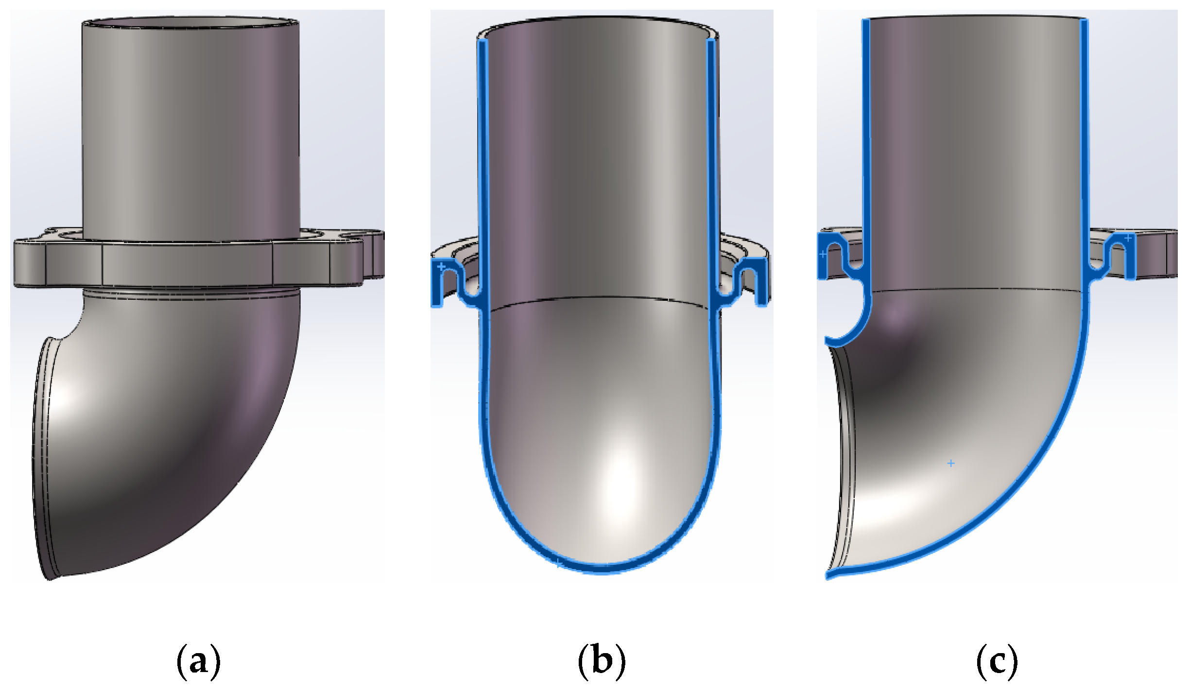
A three-dimensional model of the exhaust elbow is shown in Figure 1. The exhaust elbow construction consists of a straight pipe, flange, and elbow, with external dimensions of approximately 217 × 150 × 120 mm. Figure 1a shows the straight section of the exhaust elbow which has a length of 93 mm, an outer diameter of 90 mm, an inner diameter of 87 mm, and an average wall thickness of 1.5 mm. Figure 1b shows a flange between the two end faces which is 16 mm thick with an annular groove of 13 mm depth and less than 6 mm width on the inside. This flange has an outside diameter of 91 mm and its annular groove wall thickness is not more than 2.5 mm. Figure 1c shows the bent portion of the exhaust elbow, which has an average wall thickness of less than 2 mm. The bend is approximately 90°, and the end of the bend is 20° outward-flared. It can be seen by analyzing the structure of the exhaust elbow that the exhaust elbow has a thin wall and a large curvature. Therefore, shrinkage holes, hot cracks, and other casting defects can easily occur during the casting process.
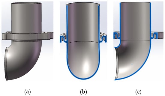
Figure 1.
Three-dimensional diagram of the exhaust elbow and its cross-section: (a) three-dimensional drawing of exhaust elbow; (b) side view; (c) front view.
2.2. Exhaust Elbow Materials
Table 1 shows the main components of the materials used for casting exhaust elbows. High-chromium–nickel austenitic stainless steel (1Cr20Ni14Si2) alloy is used for the exhaust elbows.

Table 1.
The main components of 1Cr20Ni14Si2 alloy (adapted from Ref. [30]).
2.3. Pouring System Design
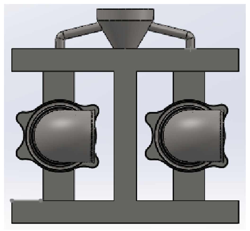
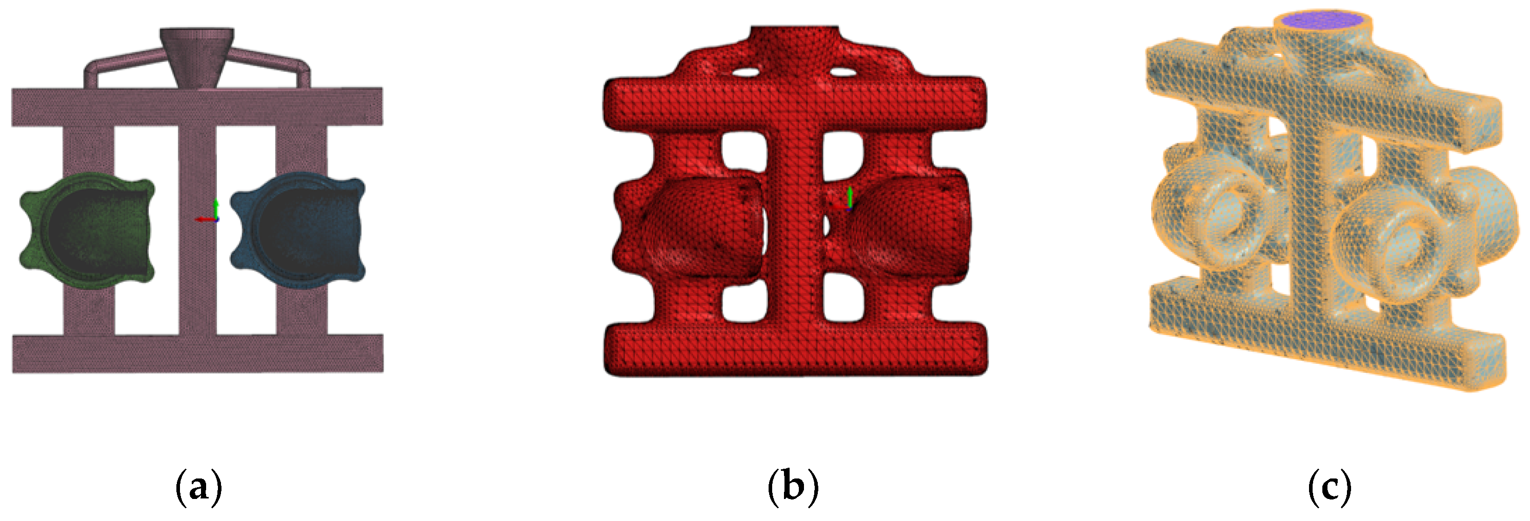
ProCAST casting simulation software (version 2021.5) is used to simulate the casting process. Ease of filling and avoiding casting flaws should be taken into account while designing the casting system [31,32,33,34]. There are high dimensional accuracy requirements for the exhaust elbow’s straight pipe and elbow at the thin-walled construction, so avoid setting up in these inner-runner sections. Nonetheless, an inner runner with a sizable cross-sectional area at the flange is achievable due to the comparatively thick flange. For two primary reasons, the inner runner is arranged with a large cross-sectional area: first, it guarantees a smooth flow of the molten metal liquid; second, it provides sufficient pressure to fill the areas of the casting with metal liquid, preventing casting flaws. The inner runner is positioned on the flange of the casting, and a side-injection type is utilized to establish four inner runners on the four lugs of the flange. The three-dimensional diagram and the mesh model are illustrated in Figure 2 below. The mesh-edge length of the casting system part and other non-focused parts is 3 mm, while the mesh-edge length of the exhaust pipe casting is 1 mm. The number of casting face meshes is 658,572, the number of casting system face meshes is 104,176, and the total number of body meshes is 2,055,150. The mesh division of the 3D group tree model of the pouring system is shown in Figure 3.
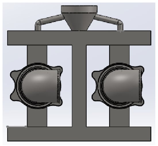
Figure 2.
Schematic diagram of the pouring system model.
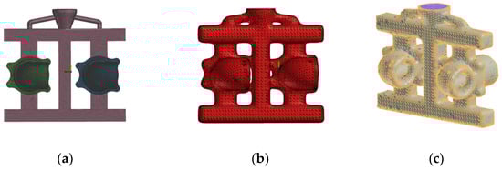
Figure 3.
Face and body meshing of the 3D group tree model of the pouring system: (a) Meshing of castings; (b) Shell face meshing; (c) Mesh division of castings and molded shells.
In the simulation process, the castings are built up with an alloy casting system type and a 1550 °C temperature. The exhaust casting’s stress type is configured to an elastoplastic model, while the casting system part’s default stress type is a linear–elastic model.
The type of mold shell is Mould Shell, the material is Chemical Mold Shell Sand, the filling is 100%, and the temperature of the mold shell is 800 °C. The rest of the parts are set to rigid.
3. Casting Process Simulation
3.1. Analysis of the Simulation Results of the Filling Process
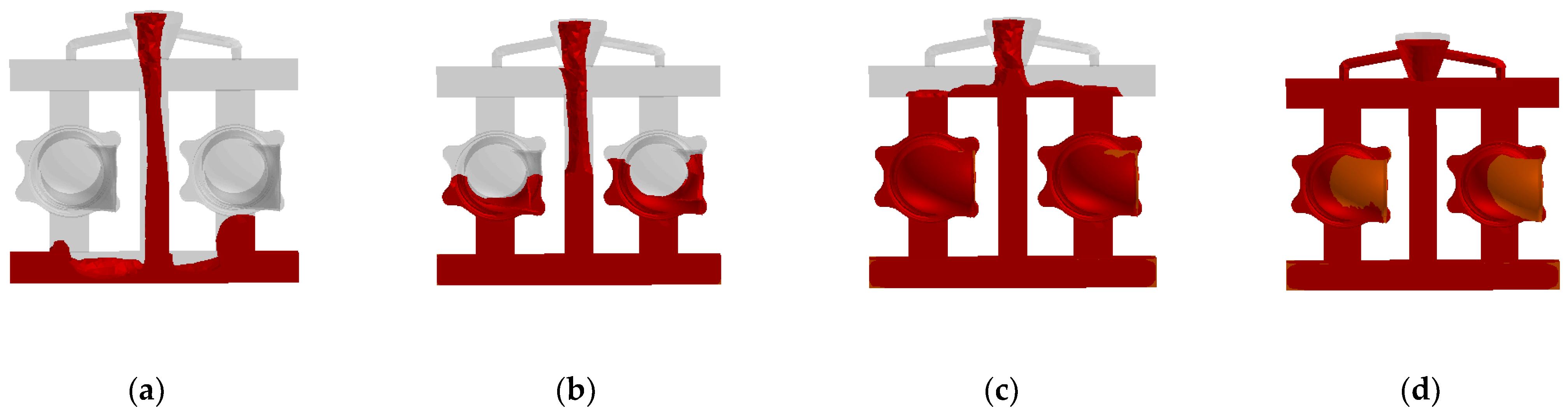
Figure 4 shows the exhaust pipe casting pouring system filling process. The liquid metal is injected from the riser and flows into the inner gate at the bottom after filling the cross gate below from the middle straight gate when the mold is filled to a quarter of its capacity. As the liquid metal moves from the gate through the straight gate to the bottom of the cross gate during liquid splashing, gas may be produced; however, this only happens in the pouring system and has no bearing on the casting. Because of its wider cross-section, the inner gate makes it easier to fill with metal liquid and prevents flaws. As shown in Figure 4c, when 75% of the mold is filled, the liquid metal has completely filled the two castings, and the top-two inner sprues are also filled. Cooling and solidification begin from the thin-walled part of the casting. When 98% of the mold is filled, the entire 3D model is filled, and cooling and solidification start at the thinnest part of the casting wall. Until the entire cavity was filled, the temperature of the alloy liquid continuously decreased throughout the filling process, and there was no underpouring of the casting. The total filling time was 9.81 s.

Figure 4.
Simulation of the filling process of the exhaust elbow: (a) 25% of the charge; (b) 50% of the charge; (c) 75% of the charge; (d) 98% of the charge.
3.2. Analysis of Simulation Results of Solidification Process
Figure 5 shows the solidification process of the exhaust elbow casting system. When the solidification volume fraction reaches 25%, the casting is essentially solidified. At this point, only the sprue and casting-connection position have a solid-phase rate of 0.6, while the rest of the casting shows a solid-phase rate between 0.9 and 1. Throughout the casting process from the position distant from the gate, the solid-phase rate hits 1 when the solidification volume fraction reaches 50%. The casting is nearly entirely solidified when the volume percentage of solidification reaches 75%, with the exception of the solid-phase ratio of 0.5 at the upper-gate intersection. The total time required for complete solidification is calculated to be 1743 s.
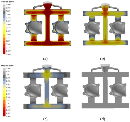
Figure 5.
Simulation of the solidification process of the exhaust elbow: (a) 25% of the charge; (b) 50% of the charge; (c) 75% of the charge; (d) 100% of the charge.
3.3. Location Distribution of Casting Defects
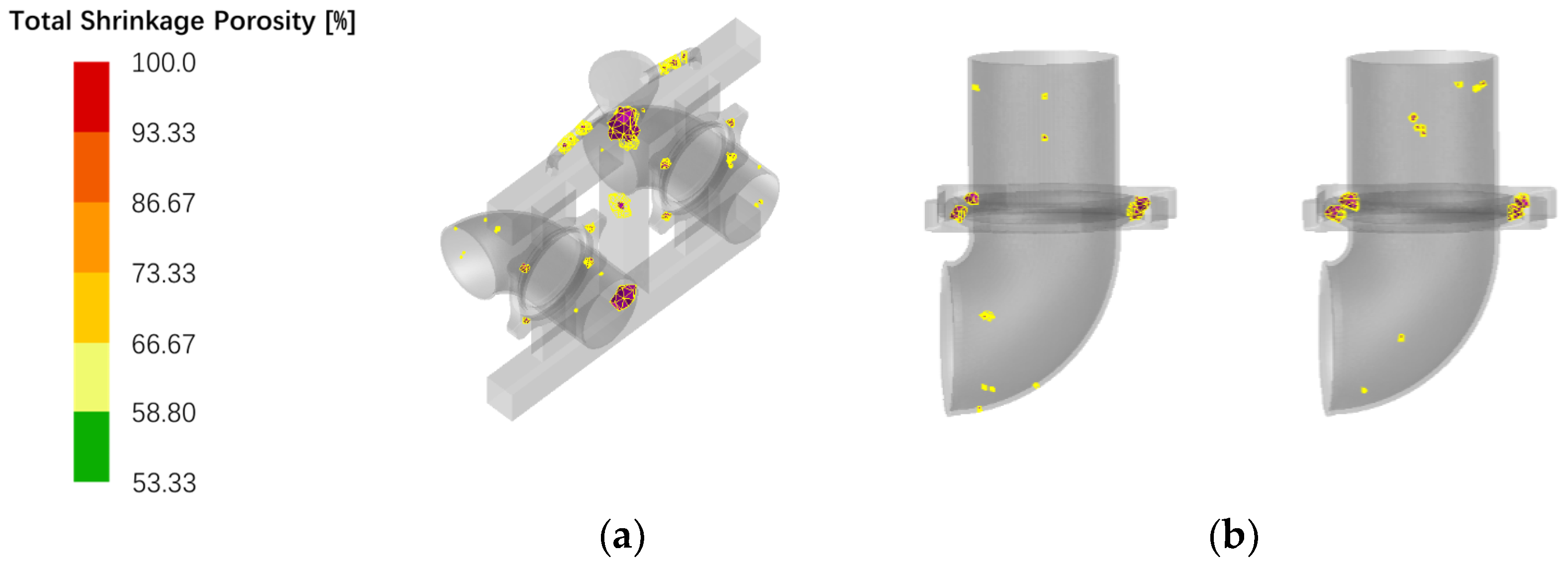
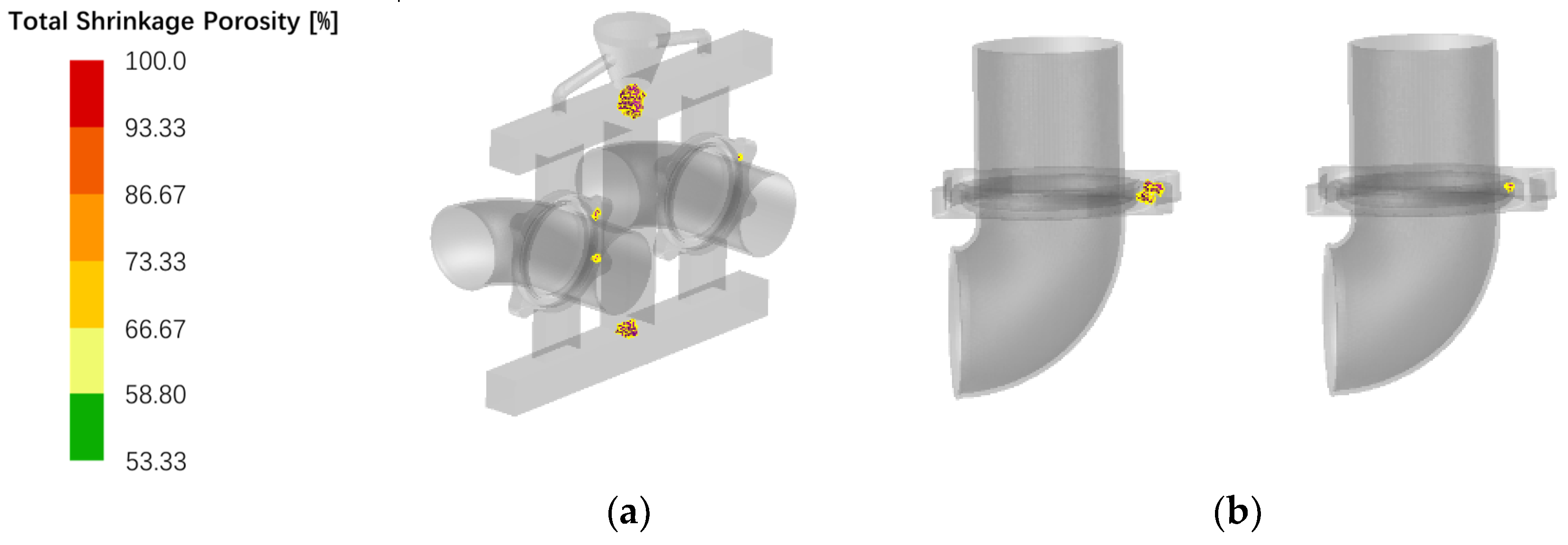
Figure 6 shows the simulation results of casting flaws. The figure indicates that shrinkage holes are the primary flaws at the corners of the casting system and at the riser–cross-gate connections. There is comparable shrinkage in both castings, mostly on the flanges, in terms of both place and proportion. However, a small amount of shrinkage was observed at the straight pipes and elbows. Calculations reveal that the total volume of shrinkage inside both castings amounts to approximately 2.12 cc, with each casting having around 1.06 cc.

Figure 6.
Exhaust elbow shrinkage distribution results: (a) Shrinkage distribution with casting system; (b) Distribution of shrinkage in castings without pouring system.
A diagram illustrating the tendency of exhaust elbow castings to crack thermally is shown in Figure 7. In the figure, (a) and (b) indicate two specific locations where thermal cracking defects may occur, respectively. Area A is the section with the highest curvature on the exhaust pipe (the vulnerable point on the exhaust pipe casting), exhibiting an average effective stress of 439.5 MPa and an HTI (Horizontal Transverse Isotropy) value of 0.000163, whereas area B shows an average effective stress of 258 MPa and an HTI value of 0.000760.
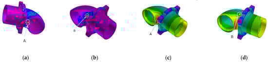
Figure 7.
Thermal cracking tendency diagram and effective stress of exhaust pipe casting: (a) Exhaust pipe bend maximum position HTI value: 0.000163; (b) Maximum position of exhaust elbow HTI: 0.000760; (c) Effective stress at area A: 439.5 MPa; (d) Effective stress at area B: 258 MPa.
3.4. Programme Optimization
3.4.1. Optimization of Casting Parameters
The casting technique was adjusted to address casting problems that showed up in the first simulations, including shrinkage, shrinkage holes, and thermal cracks. Seven groups with different pouring temperatures were utilized for simulation experiments, and the results are presented in the Table 2. At a pouring temperature of 1650 °C, the shrinkage volume of the exhaust elbow casting is minimized. Particularly, the shrinkage defects in the thin-walled part of the casting are eliminated. Shrinkage on the flange can be ignored as the flange needs to be machined later. At 1650 °C, the stress at the maximum HTI value is 272 MPa, while the ultimate yield strength of the alloy is not less than 295 MPa, and no thermal cracking defects are produced at points A and B.
Table 2.
The effect of different pouring temperature on the volume of internal shrinkage of exhaust pipe castings, HTI values, and effective stresses in A and B regions of exhaust pipe castings 1.
Seven different casting speeds are set for simulation experiments. The casting temperature and shell preheating temperature are initialized with 1550 °C and 800 °C parameters, respectively. The casting speed is simulated by taking one parameter every 0.5 s in the range of 1.5–4.5 kg/s and the results are shown in Table 3.
Table 3.
The effect of different pouring speed on the volume of internal shrinkage of exhaust pipe castings.
Seven groups with different shell preheating temperatures are established for the simulation. The results are presented in Table 4, indicating that elevating the preheating temperature of the shell can effectively minimize the shrinkage defects within the casting.
Table 4.
The size of internal shrinkage volume of exhaust pipe castings under different shell preheating temperatures.
When the preheating temperature of the shell reaches 1050 °C, it is observed that the shrinkage defects in all thin-walled parts disappear, and only a small amount of shrinkage defects are concentrated in the flange lugs. This indicates that an increase in the preheating temperature of the mold will significantly slow down the cooling and solidification rate of the alloy liquid. This can effectively guarantee continuous shrinkage of the alloy liquid in thin-wall and flange-wall sections during casting, thereby reducing the likelihood of shrinkage defects occurring.
3.4.2. Simulation of Optimal Casting Solutions
Three characteristics were combined to model the exhaust casting process and reduce faults. As shown in Figure 8, the distribution of internal shrinkage in the exhaust pipe casting is illustrated. Under these process parameters, shrinkage and shrinkage holes inside the casting are primarily concentrated in the thickest part of the flange. No shrinkage or shrinkage hole defects occur in the thin-walled sections of the casting, such as straight pipes and elbows.
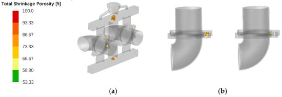
Figure 8.
Shrinkage distribution inside the exhaust pipe casting: (a) Shrinkage distribution with casting system; (b) Shrinkage distribution without casting system.
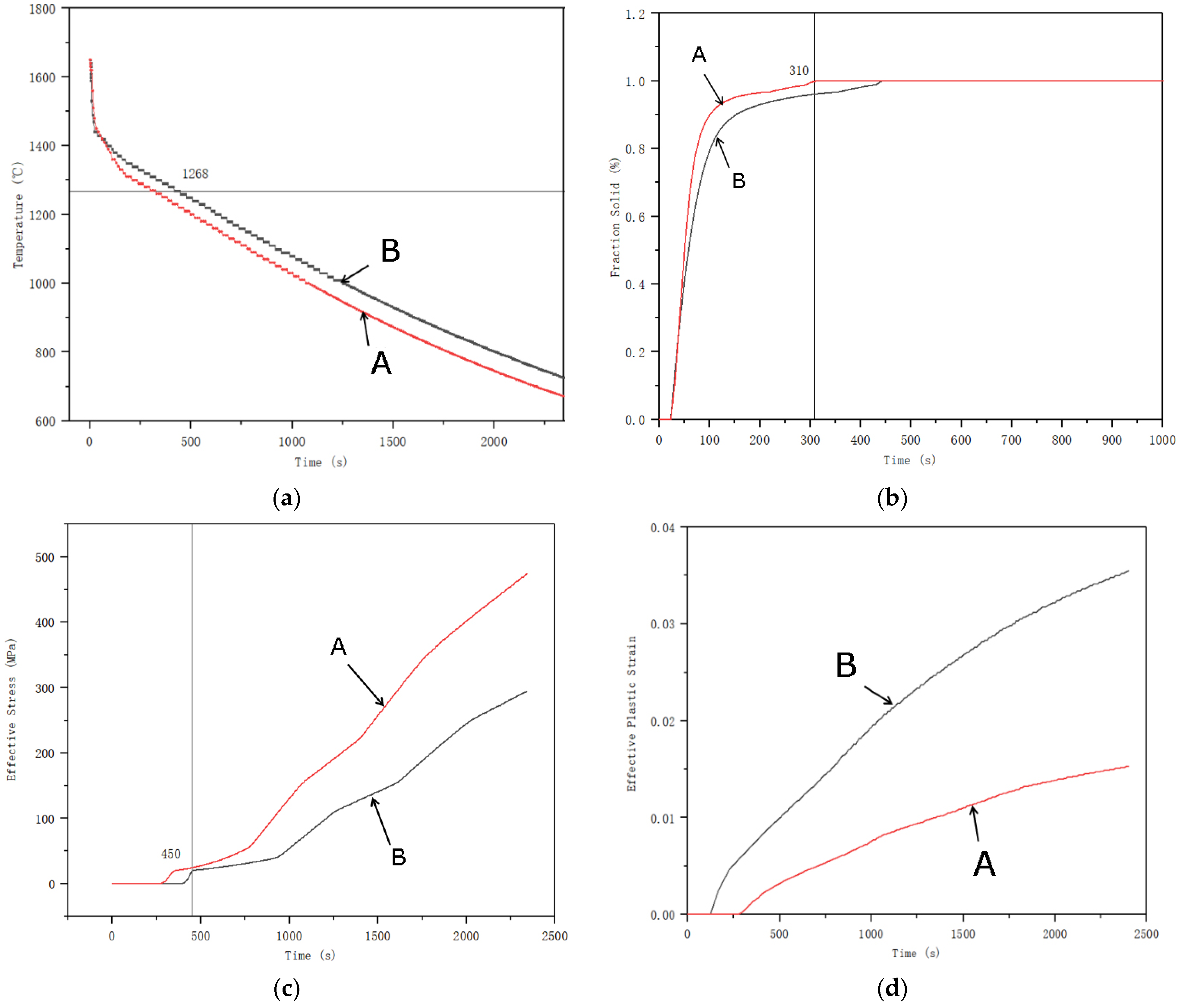
Under ideal process conditions, the dynamics of the mechanical behavior of particular exhaust bend sections A and B are depicted in Figure 9. As the temperature increases, the effective stress in the corresponding region decreases. At the end of solidification, the effective stress in regions A and B is less than 100 MPa. The corresponding elastic strain fluctuates in the range of 0.4–1%, which is small and does not show any obvious change. The mechanical behavior for both locations suggests a low probability of flaws resulting from thermal cracking at the end of solidification.
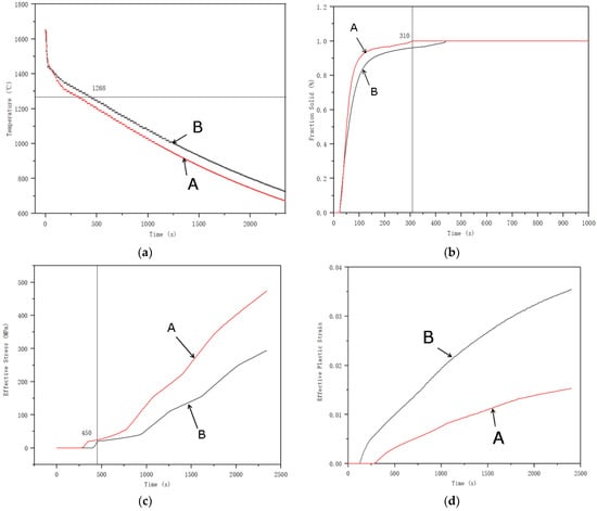
Figure 9.
Dynamic changes in mechanical behavior at specific regions A and B on the exhaust bend with optimal process parameters: (a) Temperature–Time; (b) Fraction Solid Rate–Time; (c) Effective stress–Time; (d) Effective Plastic Stress–time.
In summary, the process parameters are as follows: alloy temperature at casting is 1650 °C, casting filling speed is 1.5 kg/s, and shell temperature is 1050 °C.
4. Casting Trial Production and Process Inspection
4.1. Preparation and Production for Investment Casting
The wax molds, shells [35], and castings with a pouring system used in the trial production are shown in Figure 10. Investment casting mold shells are constructed in a continuous fashion, with the final layer sealed with slurry, for a total of four and a half layers with a wall thickness of 9–10 mm. The viscosity of the slurry used for sealing the layers is presented in Table 5.
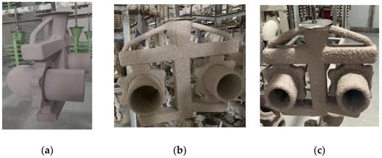
Figure 10.
Exhaust Bend Module Shell Making: (a) Surface sanding; (b) Sanding of the transition layer; (c) Backing slurry.
Table 5.
Slurry viscosity and drying process parameters for each layer.
The castings are poured separately using the original and optimized parameters. After the casting is molded, insulation is spread on the sprue location, and then it is air-cooled. After cooling, the sand shell outside the casting was removed by vibration using a vertical shell-vibration machine with a vibration impact frequency of not more than 1200 times per minute. After that, the casting was cut, polished at the sprue area, and subjected to shot blasting and pickling passivation.
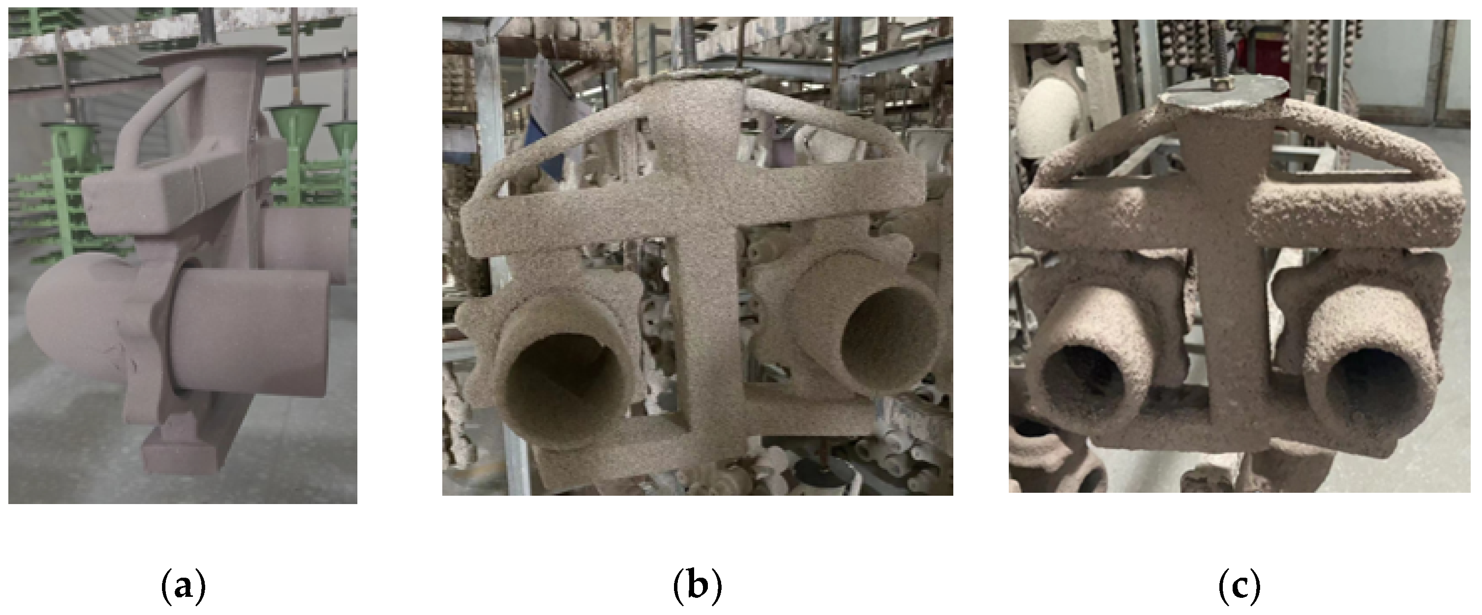
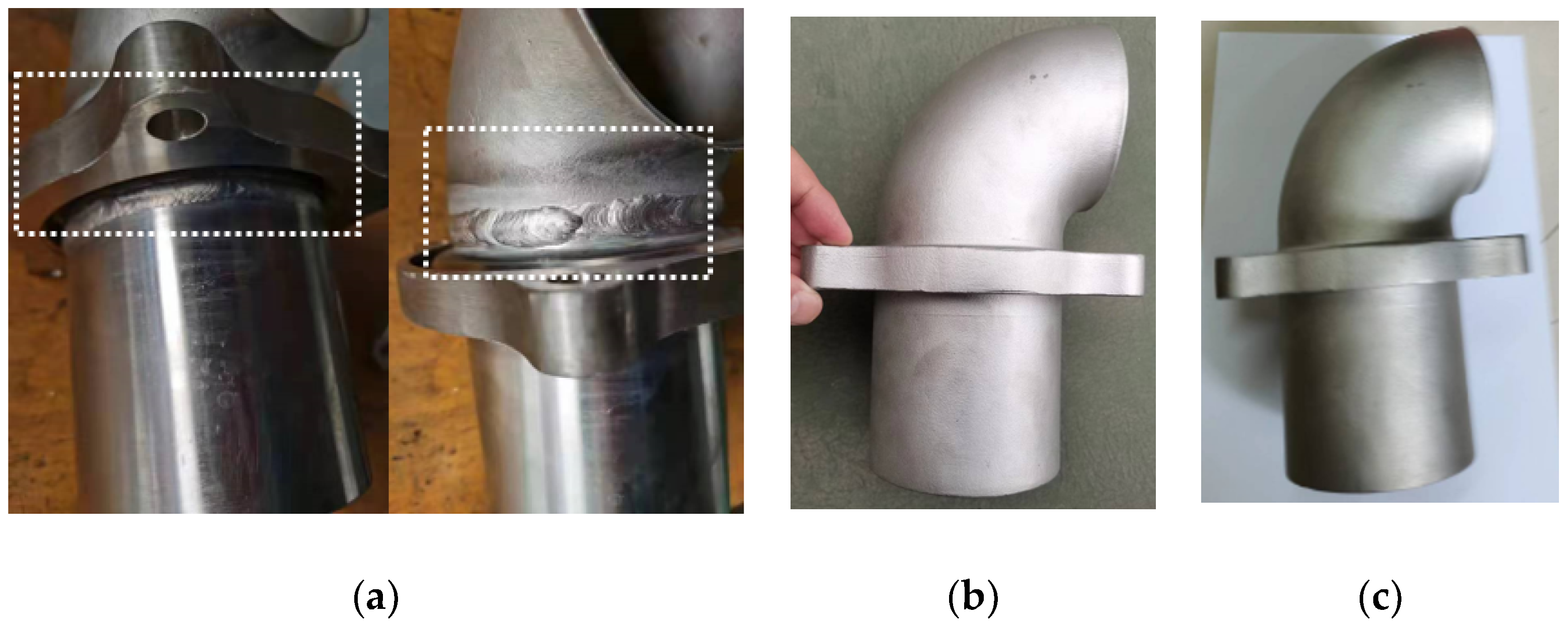
As can be clearly seen in Figure 11, the connection parts of the integrated molding process of investment casting are significantly better than those of the traditional machining–welding process. The appearance of castings before and after optimizing process parameters is essentially the same.

Figure 11.
Comparison of different process parameters: (a) Traditional machining–welding process; (b) Initial casting process parameters castings; (c) Optimized process parameters castings.
4.2. Quality Verification of Exhaust Pipe Castings
In the trial production stage of the product, a total of 12 trial production pieces were made, resulting in the successful production of 10 exhaust bend castings, with a yield rate of 83.3%. The remaining two pieces have obvious casting defects on the surface. Two factors contribute to this: first, shape damage from workers’ unavoidable operational errors during the production process; second, holes from the mold shell formed in the flange’s two annular grooves during the shell formation process: iron clamping happens when alloy liquid enters the holes during pouring. The latter was significantly improved by extending the drying time of the prepared shell.
4.2.1. Exterior Inspection of Exhaust Elbows
The dimensions of the exhaust elbow castings were measured using a Coordinate Measuring Machine (CMM) and vernier calipers, as illustrated in Table 6. Following testing, the dimensions of the produced castings align with the design specifications, and the tolerances fall within the acceptable range.
Table 6.
Exhaust elbow casting dimensional inspection results.
Visual inspection of the casting surface quality reveals a relatively high standard, with no signs of oxidized skin, mottled scars, wrinkled skin, or other defects.
4.2.2. Internal Quality Inspection of Exhaust Pipe Castings
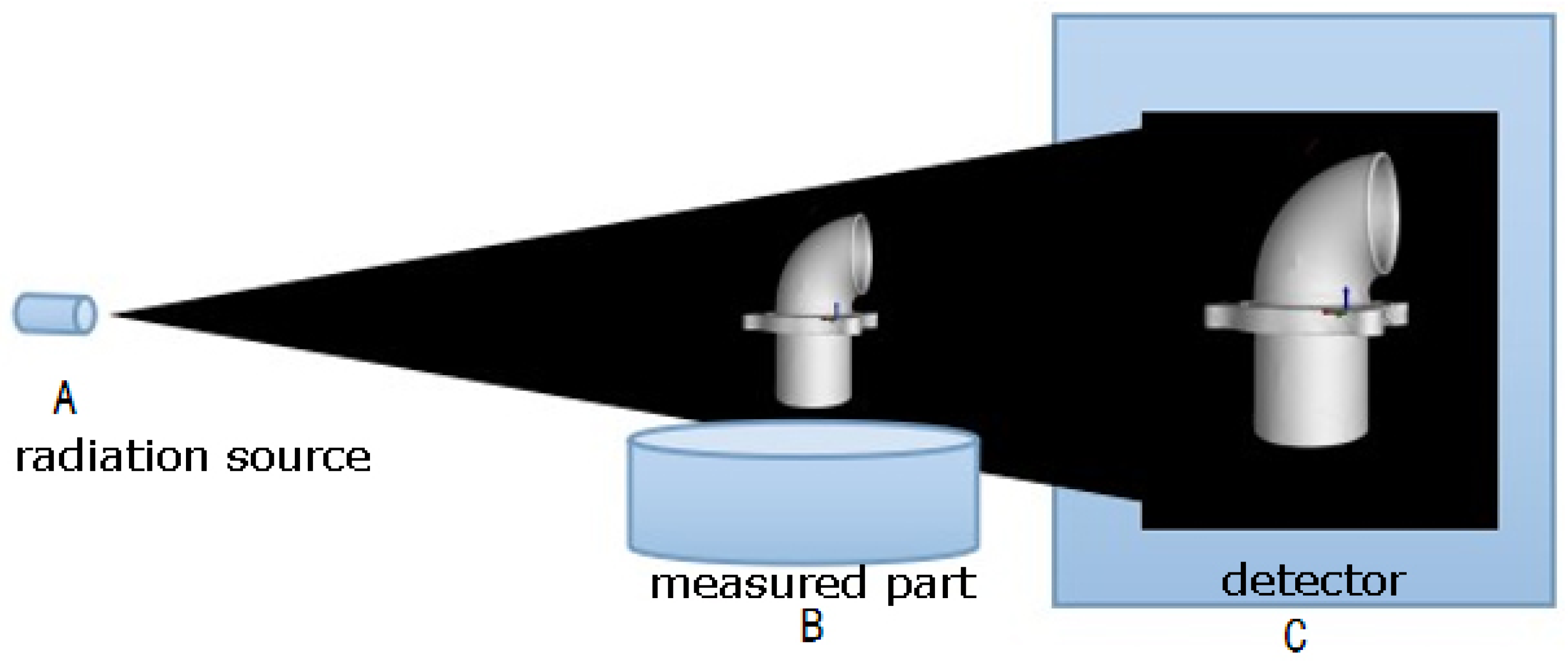
X-ray inspection equipment used: ICT-450 for industrial CT inspection [36], following inspection standards as per GB/T 29070-2012 [37]. Voltage: 430 kV, current: 1.5 mA, focal size: 0.4 mm, integration time: 1000 ms, ray source-detection distance: 1100 mm, ray source-sample distance: 700 mm. The acquisition method is a standard cone beam, with an amplitude of 1600 and a voxel size of 0.127 mm. The test method is shown in Figure 12.
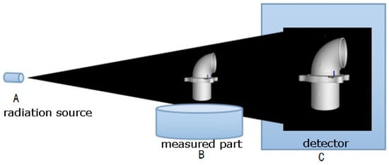
Figure 12.
Schematic diagram of industrial CT inspection.
After X-ray inspection, the exhaust elbow castings produced under the initial process parameters (casting temperature 1550 °C, casting speed 3 kg/s, shell preheating temperature 800 °C) were found to have shrinkage, shrinkage holes, and porosity defects, as shown in Figure 13. The casting shrinkage in the elbow part is generally consistent with the simulation results, and no cracks were detected.
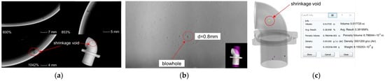
Figure 13.
CT inspection results of exhaust elbow castings under initial pouring process parameters: (a) Shrinkage of bent pipe sections; (b) Dimensions of blowhole defects in straight sections; (c) (Analogue) Bend section corresponding to shrinkage position.
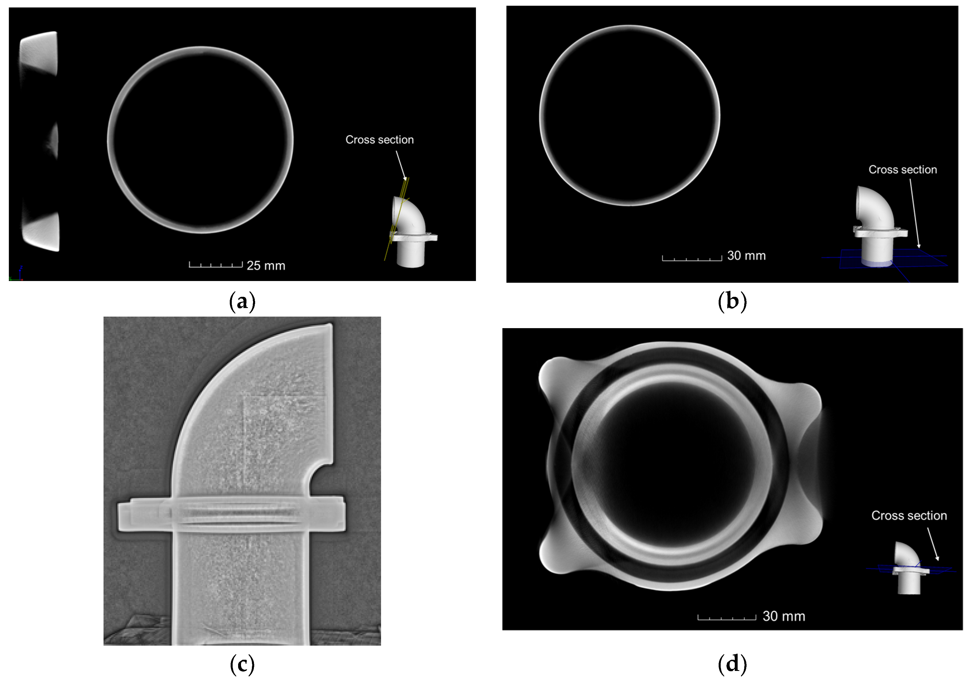
The CT section of the optimized exhaust pipe is illustrated in Figure 14. Figure 14a represents a cross-section along the center of the ring for the bend section. Figure 14b depicts a transverse section for the straight section. Figure 14c displays DR (Digital Radiography) result, and Figure 14d shows a cross-section at the flange. No shrinkage hole defects are observed in the exhaust bend castings within the bend section, straight section, and flange area. Additionally, no shrinkage phenomenon is detected in thin-walled parts or casting system hot joints, and there are no signs of thermal cracks present. The internal quality of these castings meets all requirements.
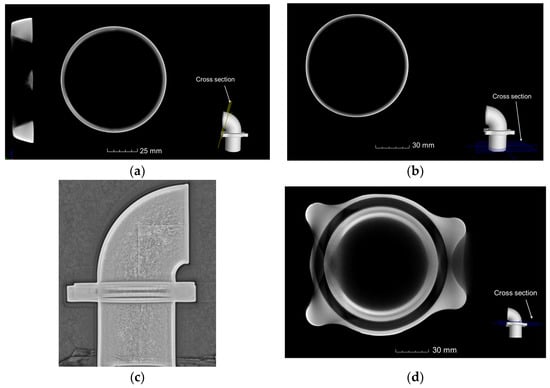
Figure 14.
CT section of exhaust elbow for casting scheme with optimized process parameters: (a) Transverse section of a bend section of pipe; (b) Transverse section of a straight section of pipe; (c) DR result; (d) Transverse section of flange.
5. Conclusions
In this paper, the precision casting process design and optimization of a high-horsepower engine exhaust pipe bend through an investment casting program are discussed.
- Determine the optimal process parameters: pouring temperature of 1650 °C, pouring speed of 1.5 kg/s, and shell preheating temperature of 1050 °C.
- Analysis of individual process parameter changes on the casting of the internal size of the volume of shrinkage: it is indicated that an increase in the preheating temperature of the mold will significantly slow down the cooling and solidification rate of the alloy liquid, thereby reducing the likelihood of shrinkage defects occurring.
- The process flow was summarized and analyzed, along with the castings manufactured before and after parameter optimization. Dimensional testing, visual inspection, and industrial CT testing were conducted to demonstrate that optimization can effectively produce castings with high internal quality, surface quality, and dimensional accuracy to achieve the desired outcomes for whole casting forming.
- The research resulted in a reduction in material and labor costs associated with machining and welding, while significantly improving product pass rates.
- The casting system has some limitations: its structure is complex, there are many redundant parts, the casting requirements are high, and maintaining a high pass rate is difficult. Future research can enhance the pouring system to decrease production costs and complexity, consequently boosting the product qualification rate.
Author Contributions
Conceptualization, methodology, software, validation, S.X.; formal analysis, investigation, resources, data curation, writing—original draft preparation, Z.L.; writing—review and editing, visualization, supervision, project administration, funding acquisition, S.D. All authors have read and agreed to the published version of the manuscript.
Funding
This work was supported by the Natural Science Basic Research Program of Shaanxi Province (Grant No.: 2023-JC-QN-0612).
Data Availability Statement
The data presented in this study are available on request from the corresponding author. The data are not publicly available due to privacy.
Conflicts of Interest
The authors declare that the research was conducted in the absence of any commercial or financial relationships that could be construed as a potential conflict of interest.
References
- Mendes, A.; Tomoyose, R. Exhaust Manifold Structural Analysis Focusing Mass Reduction for Vehicular Diesel Engine Application; SAE International: Warrendale, PA, USA, 2010. [Google Scholar] [CrossRef]
- Meda, L.; Shu, Y.; Romzek, M. Exhaust System Manifold Development; SAE Technical Paper 2012-01-0643; SAE International: Warrendale, PA, USA, 2012; p. 10. [Google Scholar] [CrossRef]
- Guo, S.C.; Zhu, Y.; Chen, D.; Gao, X.R.; Cheng, T.; Lin, Z.H. Numerical simulation of the flow performance of a diesel engine exhaust system and its structural optimization. Chin. Intern. Combust. Engine Eng. 2017, 38, 113–119. [Google Scholar]
- Galindo, J.; Luján, J.M.; Serrano, J.R.; Dolz, V.; Guilain, S. Design of an exhaust manifold to improve transient performance of a high-speed turbocharged diesel engine. Exp. Therm. Fluid Sci. 2004, 28, 863–875. [Google Scholar] [CrossRef]
- Lorenzini, M.; Barbieri, S.G.; Mangeruga, V.; Giacopini, M. Development of an experimental/numerical validation methodology for the design of exhaust manifolds of high performance internal combustion engines. Eng. Fail. Anal. 2023, 152, 1350–6307. [Google Scholar]
- Xu, Y.; Huang, S.; Su, L.; Zhang, X.; Li, Y. Elbow flow analysis and optimal exhaust port profile design. J. Mech. Sci. Technol. 2022, 2, 1251–1262. [Google Scholar] [CrossRef]
- Liu, F.; Xu, Y.; Rui, J.; Shi, Z.; Li, Y. Flow Analysis and Theoretical Design of Diesel Engine Exhaust Port. Int. J. Automot. Technol. 2020, 21, 189–196. [Google Scholar] [CrossRef]
- Bohac, S.; Landfahrer, K. Effects of pulsating flow on exhaust port flow coefficients. SAE Int. J. Engines 1999, 108, 299–309. [Google Scholar]
- Zu, B.F.; Kang, X.L.; Fu, G.Q.; Xu, Y.L.; Liu, J. Structural design and estimation on intake and exhaust ports of multi-valve engines. Trans. Chin. Soc. Agric. Mach. 2005, 36, 28–35. [Google Scholar]
- Pattnaik, S.; Karunakar, D.B.; Jha, P.K. Developments in investment casting process—A review. J. Mater. Process Technol. 2012, 212, 2332–2348. [Google Scholar] [CrossRef]
- China Foundry Association. Investment Casting Manual; China Machine Press: Beijing, China, 2000. [Google Scholar]
- Morsiya, C.V.; Pandya, S.N. Recent Advancements in Hybrid Investment Casting Process—A Review. In Proceedings of the 2nd International Conference on Recent Advances in Manufacturing (RAM 2021), Surat, India, 10–12 June 2021; pp. 817–831. [Google Scholar] [CrossRef]
- Dave, H.K.; Dixit, U.S.; Nedelcu, D. Lecture Notes in Mechanical Engineering; Springer: Singapore, 2022; pp. 817–831. [Google Scholar]
- Santos, E.C.; Shiomi, M.; Osakada, K.; Laoui, T. Rapid manufacturing of metal components by laser forming. Int. J. Mach. Tools Manuf. 2006, 46, 1459–1468. [Google Scholar] [CrossRef]
- Yuli, S.; Sungging, P. Investment Casting Simulation of ASTM F75 Acetabular Implant with Mold Pattern Orientation and Gating System Geometry Variation. Appl. Mech. Mater. 2024, 7052, 157–168. [Google Scholar]
- Kumar, P.; Singh, R.; Ahuja, I.P.S. Investigations on dimensional accuracy of the components prepared by hybrid investment casting. J. Manuf. Process 2015, 20, 525–533. [Google Scholar] [CrossRef]
- Pradhan, S.R.; Singh, R.; Banwait, S.S. Comparison of DMLS and DMLS-waste assisted investment casting. Mater. Lett. 2022, 324, 132782. [Google Scholar] [CrossRef]
- Prakash, C.; Singh, S.; Mohan, V. Comparative job production based life cycle assessment of conventional and additive manufacturing assisted investment casting of aluminium: A case study. J. Clean. Prod. 2021, 289, 125164. [Google Scholar] [CrossRef]
- Zhou, L.; Wang, D.; Cui, J.; Zhao, D.; Liu, S.; Shuai, S.; Yin, Y.; Shu, D. Modeling and experimental study on deformation prediction of thin-walled turbine blades during investment casting process. Proc. Inst. Mech. Eng. Part B J. Eng. Manuf. 2024, 238, 223–234. [Google Scholar] [CrossRef]
- Dejene, N.; Lemu, H.; Gutema, E. Critical Review of Comparative Study of Selective Laser Melting and Investment Casting for Thin-Walled Parts. Materials 2023, 16, 7346. [Google Scholar] [CrossRef] [PubMed]
- Brotzu, A.; Felli, F.; Mondal, A.; Pilone, D. Production issues in the manufacturing of TiAl turbine blades by investment casting. Procedia Struct. Integr. 2020, 25, 79–87. [Google Scholar] [CrossRef]
- Cheah, C.M.; Chua, C.K.; Lee, C.W.; Feng, C.; Totong, K. Rapid prototyping and tooling techniques: A review of applications for rapid investment casting. Int. J. Adv. Manuf. Technol. 2005, 25, 308–320. [Google Scholar] [CrossRef]
- Vaghela, J.; Valaki, J.; Thanki, S.; Pandey, A. Sustainability Analysis of Rapid Tooling-Based Investment Casting: A Comprehensive Review. Smart Sustain. Manuf. Syst. 2023, 7, 54. [Google Scholar] [CrossRef]
- Jones, S.; Yuan, C. Advances in shell moulding for investment casting. J. Mater. Process Technol. 2003, 135, 258–265. [Google Scholar] [CrossRef]
- Beeley, P.R.; Smart, R.F. Investment Casting; CRC Press: Boca Raton, FL, USA, 2023. [Google Scholar]
- Singh, S.; Kumar, R.; Kumar, R. Aluminum metal composites primed by fused deposition modeling-assisted investment casting: Hardness, surface, wear, and dimensional properties. Proc. Inst. Mech. Eng. Part L J. Mater. Des. Appl. 2022, 236, 674–691. [Google Scholar] [CrossRef]
- Kumar, P.; Ahuja, I.; Singh, R. Effect of process parameters on surface roughness of hybrid investment casting. Prog. Addit. Manuf. 2016, 1, 45. [Google Scholar] [CrossRef]
- Tewo, R.K.; Rutto, H.L.; Focke, W.; Seodigeng, T.; Koech, L.K. Formulations, development and characterization techniques of investment casting patterns. Rev. Chem. Eng. 2019, 35, 335–349. [Google Scholar] [CrossRef]
- Kumar, P.; Ahuja, I.S.; Singh, R. Experimental investigations on hardness of the biomedical implants prepared by hybrid investment casting. J. Manuf. Process 2016, 21, 160–171. [Google Scholar] [CrossRef]
- GB/T 4238-2015; Heat-Resisting Steel Plate, Sheet and Strip. China ISC S38240. Standardization Administration of China: Beijing, China, 2015.
- Liao, Q.; Ge, P.; Lu, G.; Song, Y.; Ye, W.; Gao, J.; Luo, X. Simulation Study on the Investment Casting Process of a Low-Cost Titanium Alloy Gearbox based on ProCAST. Adv. Mater. Sci. Eng. 2022, 2022, 4484762. [Google Scholar] [CrossRef]
- Zhang, X.; Li, S.; Lu, H. Simulation of Ni3Al-based Alloy and Investment Casting Process of its Thin Wall Castings. Isr. J. Chem. 2010, 47, 363–368. [Google Scholar] [CrossRef]
- Miao, L.; Tang, Z.; Zhang, D. Investment Casting Simulation and Analysis of Shell AlSi11 Alloy Part Journal. J. Phys. Conf. Ser. 2021, 2002, 12–40. [Google Scholar] [CrossRef]
- Gebelin, J.-C.; Jolly, M.R. Modelling of the investment casting process. J. Mater. Process Technol. 2003, 135, 291–300. [Google Scholar] [CrossRef]
- Yarlagadda, P.K.D.V.; Hock, T.S. Statistical analysis on accuracy of wax patterns used in investment casting process. J. Mater. Process Technol. 2003, 138, 75–81. [Google Scholar] [CrossRef]
- Silva, W.; Lopes, R.; Zscherpel, U.; Meinel, D.; Ewert, U. X-ray imaging techniques for inspection of composite pipelines. Micron 2021, 145, 103033. [Google Scholar] [CrossRef]
- GB/T 29070-2012; Non-Destructive Testing—Industrial Computed Tomography (CT) Testing—General Requirements. China ISC 19.100. Standardization Administration of China: Beijing, China, 2012.


Disclaimer/Publisher’s Note: The statements, opinions and data contained in all publications are solely those of the individual author(s) and contributor(s) and not of MDPI and/or the editor(s). MDPI and/or the editor(s) disclaim responsibility for any injury to people or property resulting from any ideas, methods, instructions or products referred to in the content. |
© 2024 by the authors. Licensee MDPI, Basel, Switzerland. This article is an open access article distributed under the terms and conditions of the Creative Commons Attribution (CC BY) license (https://creativecommons.org/licenses/by/4.0/).