Abstract
In this study, WC-Co-TiC/304 stainless steel composites were successfully prepared by compression at room temperature and vacuum sintering in a special mold. Through analysis and comparison of the microstructure, density, and particle size of WC-Co-TiC/304 stainless steel composite, the effects of different WC contents on the structure and properties of WC-Co-TiC were studied. The results show that among different WC contents when the WC content is 60%, the distribution of each structure is relatively uniform and fine, and the agglomeration of each structure is not obvious. The bonding effect of WC-Co-TiC cemented carbide and 304 stainless steel composite interface is the best. With the increase of WC content, the side defects of WC-Co-TiC cemented carbide increase gradually. When WC content is 60%, the best ratio is 1:1 of Co/TiC, as the density is 94.45%, the particle size of 0.2–0.3 μm is 38.9%, and the highest hardness of WC-Co-TiC cemented carbide side is 1370 HV0.1, but it is better when the ratio of Co/TiC is 3:2 at the composite interface, as the hardness value is 852 HV0.1 and the diffusion of Cr element is more uniform, while other elements have little difference.
1. Introduction
The ideal material for printed circuit board micro drills should have the characteristics of “three high”, namely high wear resistance, high toughness, and high thermal conductivity [1]. Nowadays, they are mostly made of high-toughness cemented carbide or cobalt steel with fine grains [2,3]. In order to further reduce the manufacturing cost of micro bits, use less cemented carbide, and meet the increasing output and performance requirements of the micro bit material industry, it is necessary to develop composite micro bit materials with excellent performance. In fact, this has aroused increasing interest in the field of cemented carbide metal matrix composites [4]. Cheniti et al. [5] studied the diffusion bonding between WC Co/Ni and stainless steel bimetallic composites. When the composite was kept at 950 °C for 80 min, the maximum tensile strength of the composite interface reached 195 Mpa. The author also observed the diffusion layer produced by the mutual diffusion of alloy elements. Soria et al. [6] studied the connection between WC-12Co cermet and AISI 304 stainless steel using microwave composite heating technology and found that ternary carbides of intermetallic compounds are formed at the interface of the joint, which indicates that the hardness of the joint is very high. Najar et al. [7] studied the bonding between WC-Co-TiC and steel using different interlayer coatings such as CrN, ZrN, and TiCxN1–x. Hasan et al. [8] combined WC with stainless steel, but the study lacked research on the microstructure and metallurgy of joint interfaces. These studies indicate the possibility of composites of cemented carbide and stainless steel.
Tungsten titanium cobalt carbide, also known as YT cemented carbide, is an alloy cemented carbide material composed of tungsten carbide (WC), titanium carbide (TiC) and metal (Co). It has the characteristics of high hardness, high temperature resistance, good wear resistance, and strong oxidation resistance and is often used as an important tool material for cutting, wear-resistant parts, and high temperature resistance [9]. On the other hand, 304 stainless steel is a good substitute material because of its corrosion resistance, heat resistance, high compressive strength, and wear resistance. It is an important challenge to prepare WC-Co-TiC and 304 stainless steel composites to combine their properties [10]. The properties of cemented carbide are affected by not only sintering temperature, powder size, and other factors but also the content ratio of cemented carbide powder.A study by Luo et al. [11] indicated that with an increase of carbon content, the density and hardness of WC-15TiC Co alloy decreased, and the transverse fracture strength and fracture toughness first increased and then decreased. The alloy with appropriate carbon content has better comprehensive properties. Tang et al. [12] found that with the decrease of WC content, the average particle size of the hard phase decreases, the crystalline integrity of WC becomes worse, the hardness of the alloy increases, and the bending strength first increases and then decreases. Therefore, combining ultrafine-grained WC-Co-TiC cemented carbide with 304 stainless steel must take into account the problem of WC content.
In this experiment, the powder and the solid were put into a special mold and compressed at room temperature and then sintered under vacuum. By changing the WC content, macrocontrolling the proportion of Co and TiC, and then changing the proportion of the three powders, the best proportion of composite with 304 stainless steel was found, and the composite of ultrafine-grained WC-Co-TiC and 304 stainless steel was successfully prepared. The influence of different WC content on the interface microstructure of the WC-Co-TiC/304 stainless steel composite and the element diffusion at the interface of the composite were studied.
2. Materials and Methods
2.1. Experimental Materials
WC-Co-TiC/304 stainless steel composite is made by mixing nano-cemented carbide powder and 304 stainless steel, then loading the mixture into a self-made mold for pressing and vacuum sintering. The raw materials used in the experiment are the particle size of 200 nm WC powder (composition is shown in Table 1), Co powder (composition is shown in Table 2), and TiC powder (composition is shown in Table 3). Their original morphology and mixed morphology are shown in Figure 1. The middle core is made of 304 stainless steel with a diameter of 1 mm (composition is shown in Table 4).

Table 1.
Chemical composition of WC powder (mass fraction, %).
Table 2.
Chemical composition of Co powder (mass fraction, %).
Table 3.
Chemical composition of TiC powder (mass fraction, %).
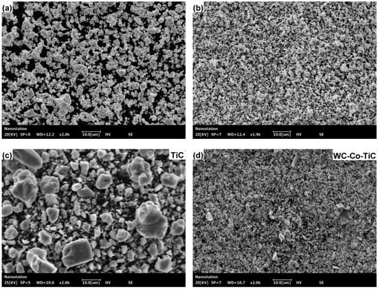
Figure 1.
SEM image of WC-Co-TiC cemented carbide: (a) WC powder; (b) Co powder; (c) TiC powder; (d) WC-Co-TiC powder.
Table 4.
Chemical composition of 304 stainless steel (mass Fraction, %).
2.2. Experimental Preparation
The nanometer cemented carbide powder needs a planetary ball mill (Retsch PM 100) for uniform mixing. The ball milling time is 2 h, the rotating speed is 200 r/min, and the ball milling mass ratio is 5:1. The mold required for the experiment is self-made, as shown in Figure 2. The experiment uses a universal testing machine (WDW-300, Jinan, China) as the blank pressing equipment, with a compression speed of 1 mm/min and a load range of 1132–1415 N/mm2. A vacuum tube furnace (GR.TF60, Shanghai, China) is used for high-temperature sintering. The sintering temperature is set at 1280 °C, the heating rate is 5 °C/min, and the holding time is 90 min. After holding, the furnace is cooled to room temperature.
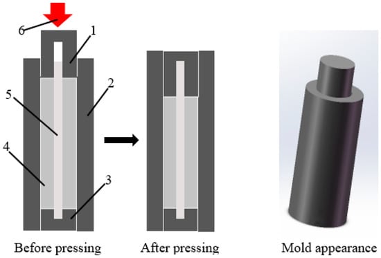
Figure 2.
WC-Co-TiC/304 stainless steel composite preparation mold. 1, Plug; 2, Setting mold; 3, Base; 4, 304 stainless steel core; 5, Mixed powder material; 6, Pressure.
The stamping process involved the following:
1. Material preparation: Insert 304 stainless steel rod into the base, put WC-Co-TiC cemented carbide powder into the base after the base is combined with the molding mold, and cover the plug.
2. Perform stamping: Press the plug under high pressure until it enters the molding mold. The plug and the base are provided with the same holes to protect the 304 stainless steel rod from excessive deformation.
2.3. Experimental Detection
The metallographic microstructure was observed with a digital microscope (VHX-5000, Shenzhen, China). A Thermo Scientific Apreo 2S multifunctional field emission scanning electron microscope (Apreo 2S, Waltham, America) was used to observe the microstructure of the sample and composite interface, point scanning analysis was conducted on the cemented carbide side by self-contained energy dispersive spectrometer (EDS), and the element distribution at the composite interface was analyzed by line scanning and surface scanning. ImageJ is used to adjust the grayscale threshold value (0–70, 70–150, 150–230, 230–255) of the particle SEM image to characterize the contour, and Frette diameter data is automatically generated. These data are used for frequency distribution statistics through the original to obtain the particle distribution. The Vickers hardness test is carried out on the cross section of WC-Co-TiC/304 stainless steel composite material by using a microhardness tester (Q10M, QNESS, Golling an der Salzach, Austria) under the condition that the loading pressure is 0.1 kg and the holding time is 10 s. The dotting method starts from the center of 304 stainless steel along the radius direction, and each sample hits 6 points. The average value of 3 measurements at each point will then be taken. The phase of WC-Co-TiC/304 stainless steel composite interface was detected by an X-ray diffraction analyzer (D8 Advance XRD, Karlsruher, Germany), and the analysis results were obtained by Highscore software (3.0e (3.0.5), HighScore Plus, Almelo, Holland).
2.4. Experimental Scheme
This experiment is divided into two series, A and B. The experimental scheme is shown in Table 5. Series A is a WC-Co-TiC/304 stainless steel composite with different WC content. Series B is a further exploration of WC-Co-TiC/304 stainless steel composite with corresponding WC content. The best composite effect is found by changing the Co/TiC ratio.
Table 5.
WC-Co-TiC content proportioning table.
3. Results and Discussion
3.1. Effect of Different WC Content (Co:TiC = 1:1) on TiC-WC/304 Stainless Steel Composite
Series A changes the Co content and TiC content by adjusting and controlling different WC content, and the proportion of Co content and TiC content is determined as 1:1. Observe the composition of WC-Co-TiC/304 stainless steel composite to find the best WC content.
3.1.1. Effect of Different WC Content on Surface Porosity of Microstructure of WC-Co-TiC/304 Stainless Steel Composite
We conducted point scanning analysis on the microstructure of cemented carbide side through Thermo Scientific Apreo 2S multifunctional field emission scanning electron microscope and obtained the SEM image (Figure 3). Figure 3 shows the microstructure of WC-Co-TiC cemented carbide with 60% WC at a Co/TiC content ratio of 1:1. Through observation, we know that the boundaries of each structure are obvious at each WC content. It is preliminarily judged that three kinds of structures exist in the WC-Co-TiC cemented carbide structure, which is divided into white (A), gray (B), and black (C) according to the gray scale of the color. The above three kinds of structures are respectively spot-scanned to obtain the corresponding element content of the structure, as shown in Table 6.
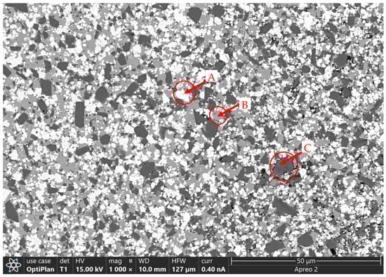
Figure 3.
SEM image of the microstructure of WC-Co-TiC cemented carbide with 60% WC.
Table 6.
Chemical element composition table of A, B and C.
It can be seen from Table 6 that the white tissue at point A is mostly composed of WC, the gray tissue at point B is mainly composed of Co elements, and the black tissue at point C is composed of TiC.
Figure 4 shows the microstructure of WC-Co-TiC cemented carbide with different WC content at Co/TiC = 1:1. As shown in Figure 4a, when the WC content is 50%, the micropores of WC-Co-TiC microstructure are not easily observed. In Figure 4b,d, when the WC content is 60% and 80%, compared with other WC content, the number of micropores in the microstructure of WC-Co-TiC is similar or greater. Finally, when the WC content is 70%, compared with other WC content, the micropores of WC-Co-TiC microstructure are obvious and greatest.
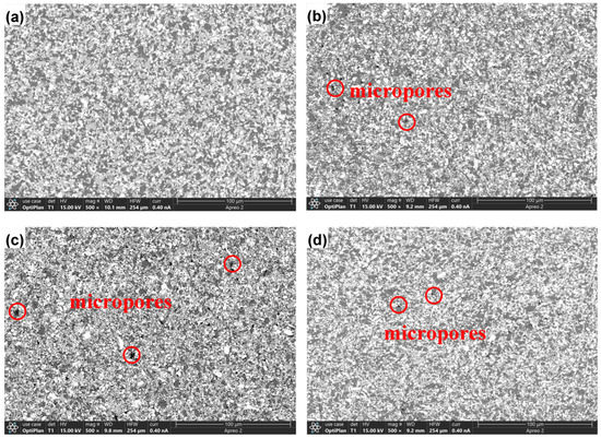
Figure 4.
SEM image of WC-Co-TiC cemented carbide structure of A series: (a) 50% WC; (b) 60% WC; (c) 70% WC; (d) 80% WC.
After processing the microstructure image of WC-Co-TiC cemented carbide, the pore distribution image is obtained as can be seen in Figure 5. When the WC content is 50%, the pore distribution is relatively uniform and small, and the number is also small, while 60%, 70% and 80% of the pores are large, and the number is significantly increased. This is because the Cockendall effect is produced during the sintering process. WC dissolves into TiC to form a replacement solid solution. With the increase of WC content, the number of fine-grained WC in the solution-reprecipitation process increases, and some solid solutions also increase with the increase of WC content. Therefore, the plane movement in the diffusion region also increases, forming a large number of pores. This is roughly the same as the result observed in Figure 4.
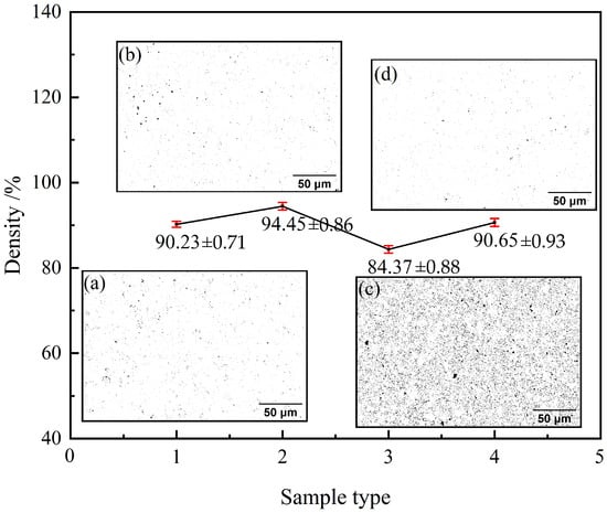
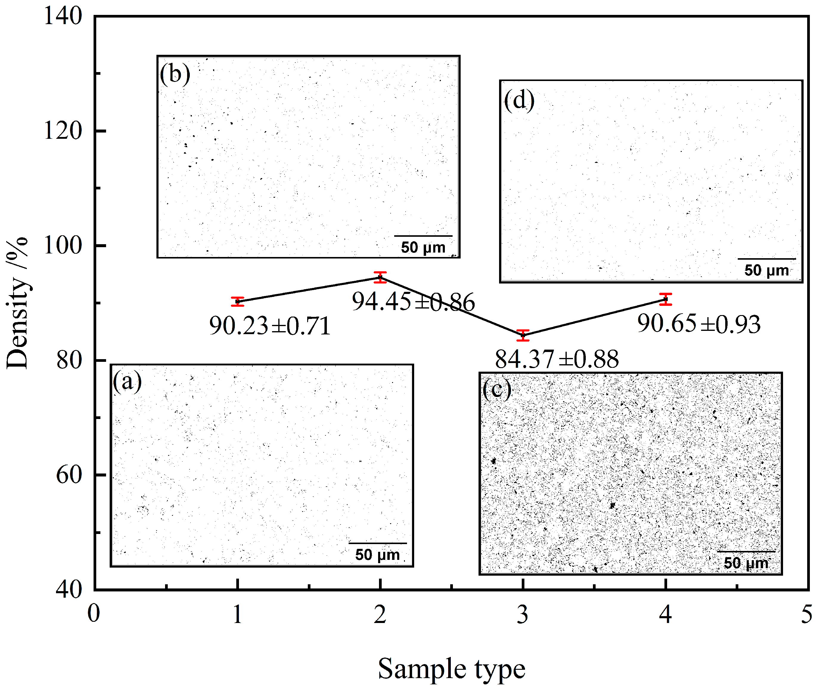
Figure 5.
Microstructure density of WC-Co-TiC cemented carbides of A series: (a) 50% WC; (b) 60% WC; (c) 70% WC; (d) 80% WC.
The data in Figure 5 show the density of WC-Co-TiC cemented carbides with different WC contents when the Co/TiC content ratio is 1:1. When the WC content is 60%, the density of WC-Co TiC cemented carbides is the highest, with the highest value being 94.45%. When the average particle size of WC is 50% and 80%, there is little difference in the microstructure density of WC-Co-TiC cemented carbide, which is 90.23% and 90.65%, respectively. When the WC content is 70%, the microstructure density of WC-Co-TiC cemented carbide is the lowest, and the lowest value is 84.37%. Therefore, with the increase of WC content, the microstructure density of WC-Co-TiC cemented carbide first increases and then decreases, reaching the maximum value of 94.45% when the WC content is 60%. The micropores on the same side may be due to the WC-Co-TiC cemented carbide being closer to the combination of 304 stainless steel. At the same time, the different linear expansion coefficients also affect the generation of microcracks.
3.1.2. Particle Size Distribution of WC-Co-TiC/304 Stainless Steel Composite with Different WC Content
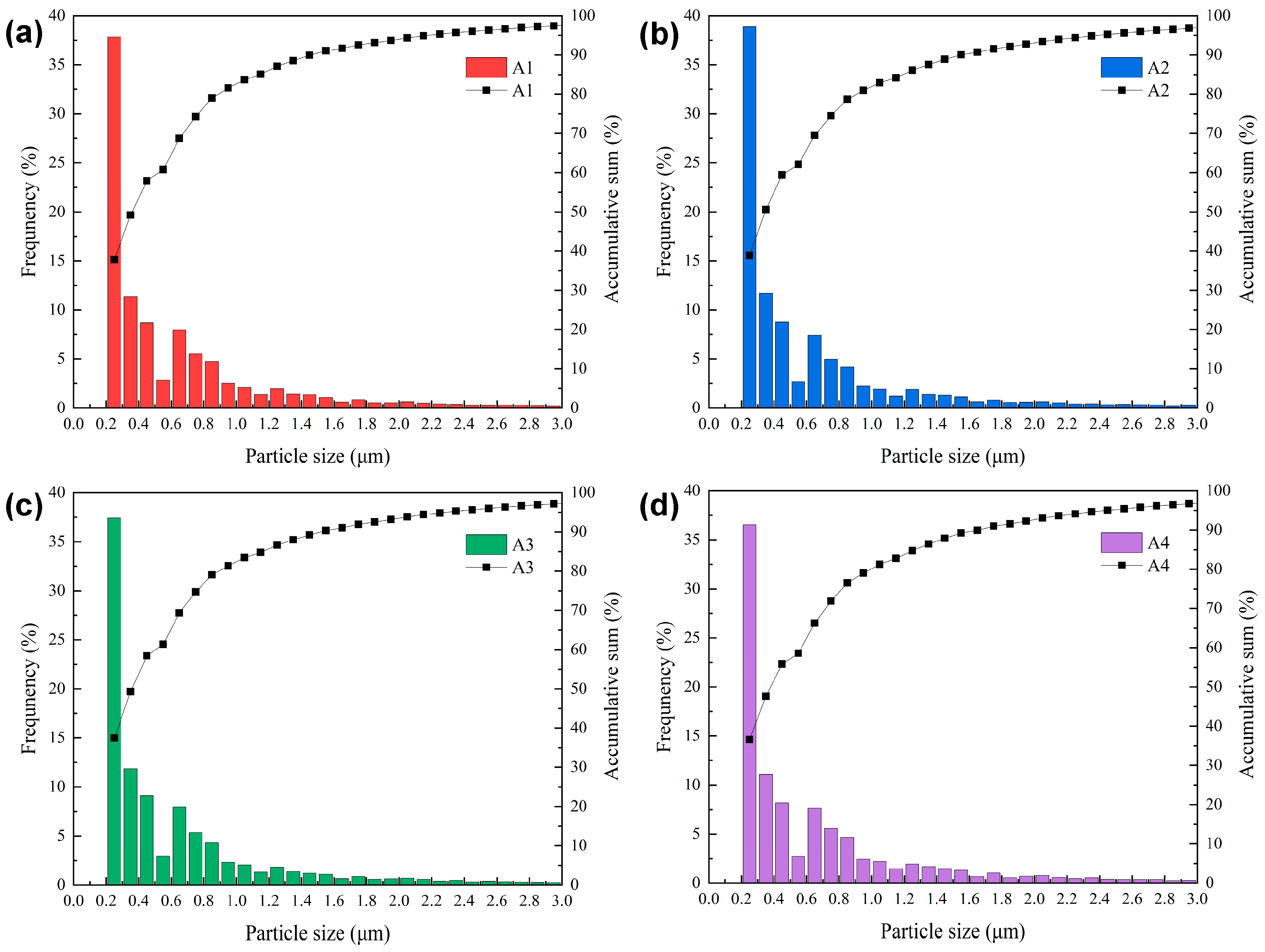
Figure 6 shows the statistical images of particle size data of WC-Co-TiC cemented carbides with different WC contents when the Co/TiC content ratio is 1:1. It can be seen from the figure that when the WC content is 50%, most particle sizes are 0.2~0.4 μm, and the grains are fine. When WC content is 60%, the grains are mainly distributed in 0.2~0.4 μm particle sizes, but 0.2~0.3 μm particles decreased by about 1.1%. When the WC content is 70%, the particle size distribution is relatively uniform, and the grains are mainly distributed in 0.2~0.4 μm particle sizes, similar to 60%. When WC particle size is 80%, the grain distribution is 0.2~0.4 μm particle sizes. The fraction is the least as compared to other WC contents. When the Co/TiC content ratio is 1:1, the particle size gradually increases with the increase of WC content. When the WC content is 80%, the distribution of particle size of 0.2~0.4 μm is 1.3% smaller than when WC content is 50%.
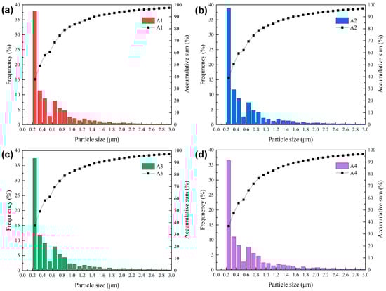
Figure 6.
Particle size distribution image of WC-Co-TiC cemented carbides of A series: (a) 50% WC; (b) 60% WC; (c) 70% WC; (d) 80% WC.
3.1.3. Effect of Different WC Content on Interface Morphology of TiC-WC/304 Stainless Steel Composite
Figure 7 shows the composite interface of WC-Co-TiC/304 stainless steel compound with different WC content when the Co/TiC content ratio is 1:1. When the WC content is 50%, the composite effect of WC-Co-TiC cemented carbide and 304 stainless steel is significant, and many small cracks appear on the side of 304 stainless steel. When the content of WC is 60%, a transition layer appears at the composite interface of WC-Co-TiC cemented carbide and 304 stainless steel, but many micropores appear on the side of 304 stainless steel. When the WC content is 70%, the composite effect of WC-Co-TiC cemented carbide and 304 stainless steel is remarkable, and there is an obvious transition layer, but there are still micropores. When the WC content is 80%, the interface of WC-Co-TiC/304 stainless steel composite also has a transition layer, but there are microcracks on the side of WC-Co-TiC cemented carbide. Therefore, with the increase of WC content, the composite interface of WC-Co-TiC/304 stainless steel composite is gradually obvious, and the side defects of WC-Co/TiC cemented carbide increase. Compared with other materials, when WC content is 60%, the composite effect is the best.

Figure 7.
SEM image of composite interface of WC-Co-TiC/304 stainless steel composite of A series: (a) 50% WC; (b) 60% WC; (c) 70% WC; (d) 80% WC.
3.2. Effect of Different WC Content (Co:TiC = 3:2) on WC-Co-TiC/304 Stainless Steel Composite
Series B changes the proportion of Co content and TiC content by determining WC content so as to adjust Co content and TiC content. Observe the composition of WC-Co-TiC/304 stainless steel composite and find the best proportion of Co content and TiC content.
3.2.1. Effect of Different WC Content on Surface Porosity of Microstructure of WC-Co-TiC/304 Stainless Steel Composite
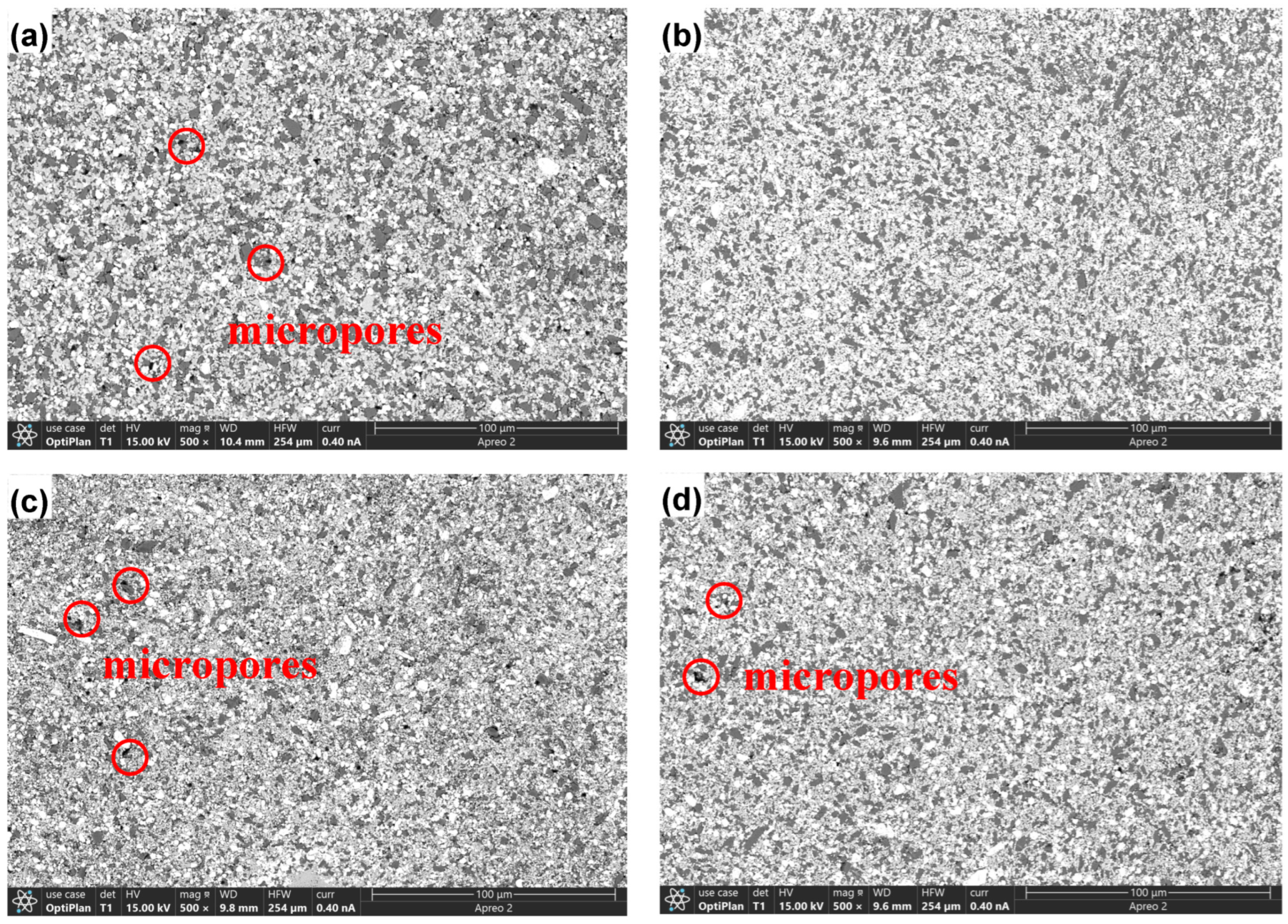
Figure 8 shows the microstructure of WC-Co-TiC cemented carbide with different WC contents at Co/TiC = 3:2. In Figure 8a,c, when WC content is 50% and 70%, the number of micropores in WC-Co-TiC microstructure is similar and the largest compared with other WC content. In Figure 8b, when the WC content is 60%, it is not easy to observe the micropores of WC-Co-TiC microstructure. Finally, when the content of WC is 80%, compared with other WC contents, there are a few micropores in the microstructure of WC-Co-TiC.
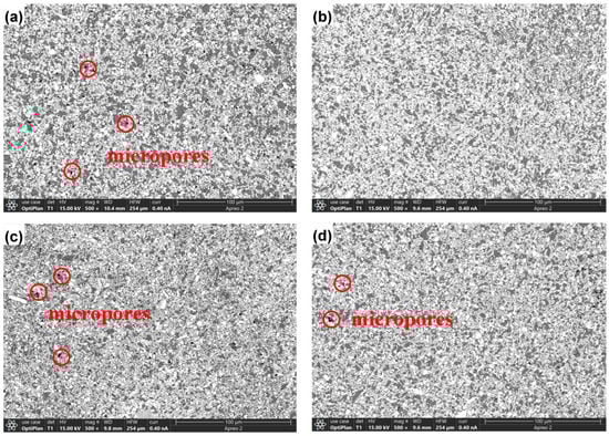
Figure 8.
SEM image of microstructure of WC-Co-TiC cemented carbide of B series: (a) 50% WC; (b) 60% WC; (c) 70% WC; (d) 80% WC.
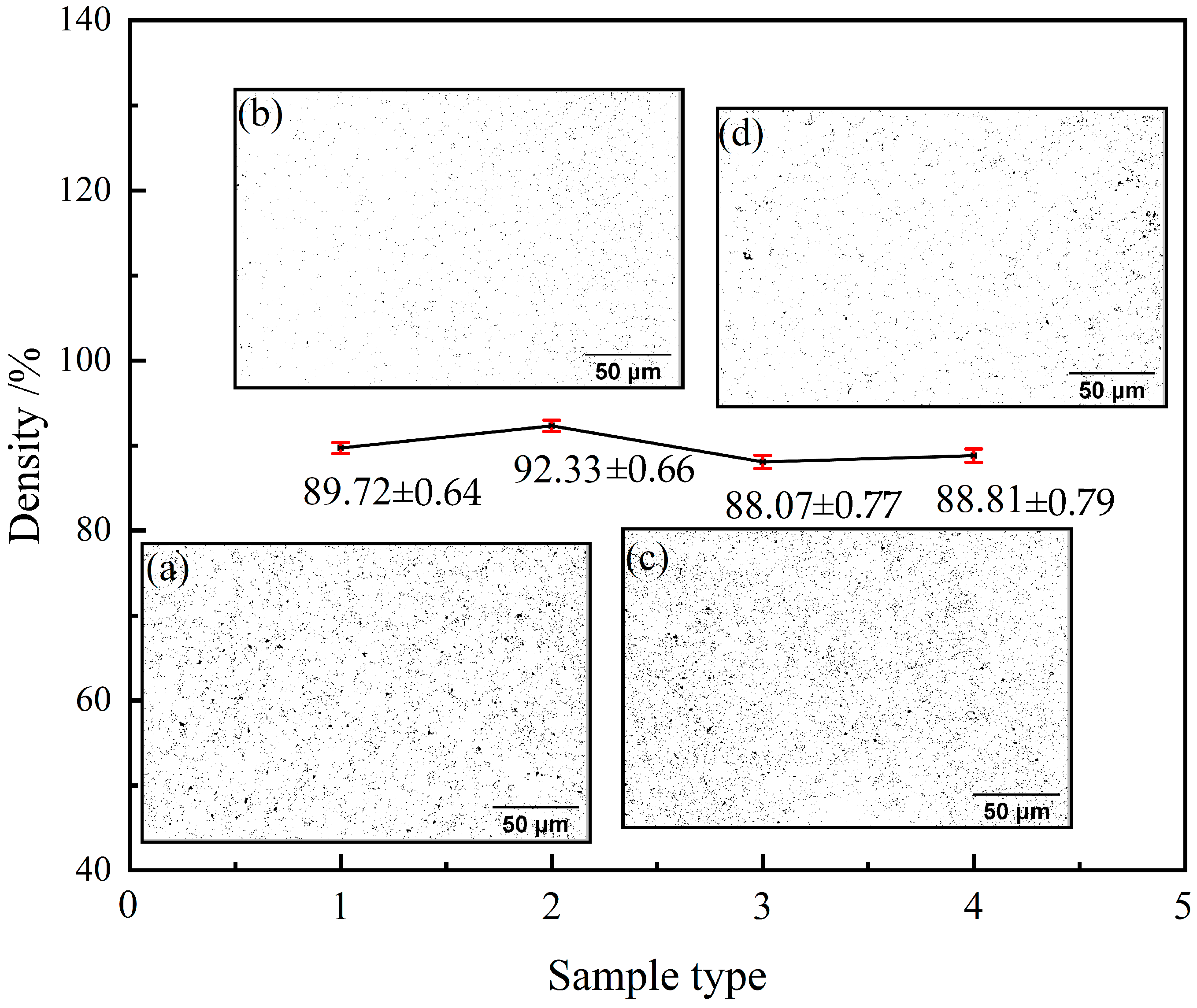
The pore distribution image is obtained after the organization image of
WC-Co-TiC cemented carbide is processed. It can be seen from Figure 9 that when the WC content is 50% and 70%, large pores appear, and the number increases significantly, while when the WC content is 60% and 80%, the pore distribution is relatively uniform and small, and the number is small. This is roughly the same as the result observed in Figure 8.
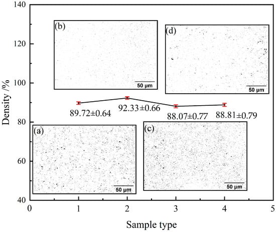
Figure 9.
Microstructure density of WC-Co-TiC cemented carbides of B series: (a) 50% WC; (b) 60% WC; (c) 70% WC; (d) 80% WC.
The data in Figure 9 show the microstructure density of WC-Co-TiC cemented carbides with different WC contents when the Co/TiC content ratio is 3:2. When the WC content is 50%, the microstructure density of WC-Co-TiC cemented carbides is 89.72%. When the WC content is 60%, the microstructure density of WC-Co-TiC cemented carbide is the highest, the highest value being 92.33%. When the average particle size of WC is 70% and 80%, the microstructure density of WC-Co-TiC cemented carbide shows little difference, which is 88.07% and 88.81%, respectively. Therefore, with the increase of WC content, the microstructure density of WC-Co-TiC cemented carbide first increases and then decreases, reaching the maximum value of 92.33% when the WC content is 60%.
3.2.2. Particle Size Distribution of WC-Co-TiC/304 Stainless Steel Composite with Different WC Content
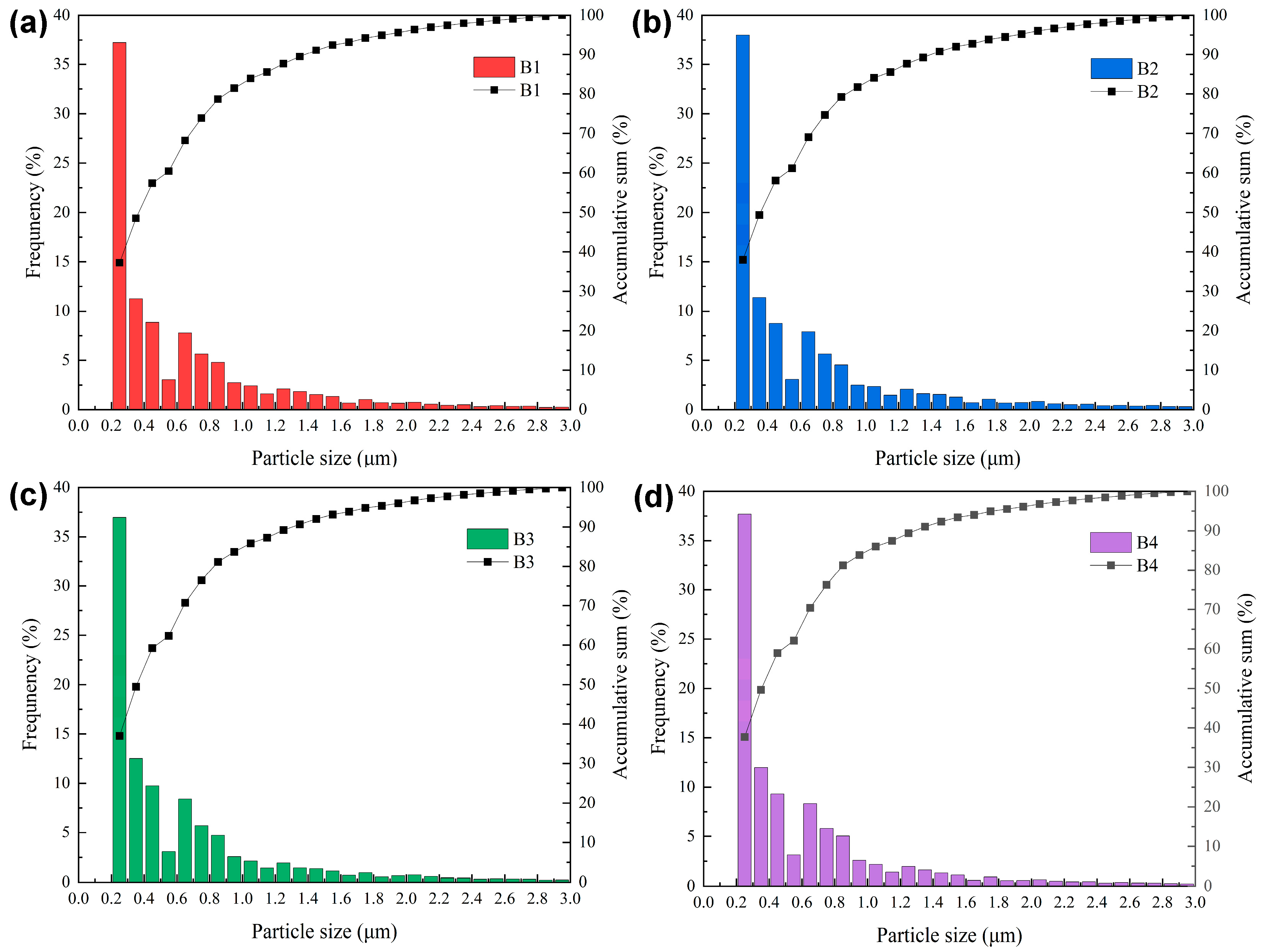
Figure 10 shows the statistical image of particle size data of WC-Co-TiC cemented carbides with different WC contents when the Co/TiC content ratio is 3:2. It can be seen from the figure that when the WC content is 50%, the grain distribution is 0.2~0.4 μm particle sizes, and the part is less than other WC contents. When WC content is 60%, the grains are mainly distributed in 0.2~0.4 μm particle sizes, which is the largest compared with other WC contents. When the WC content is 70%, the particle size distribution is relatively uniform, and the grains are mainly distributed in 0.2~0.4 μm particle sizes. When WC content is 80%, the grains are mainly distributed in 0.2~0.4 μm particle sizes, accounting for 49.7%. When the Co/TiC content ratio is 3:2, the particle size first increases and then decreases with the increase of WC content. When the WC content is 60%, the particle size ranges from 0.2 to 0.4 μm The distribution is the highest, with the highest being 38.0%.
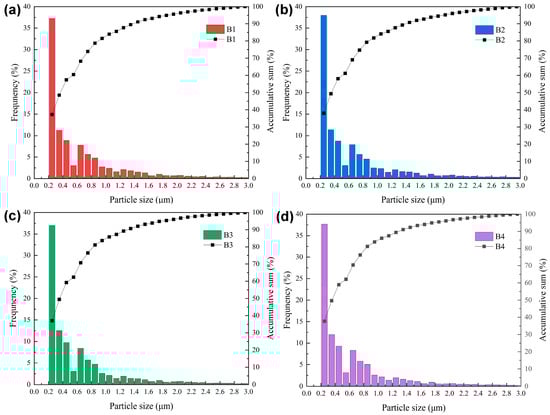
Figure 10.
Particle size distribution image of WC-Co-TiC cemented carbides of B series: (a) 50% WC; (b) 60% WC; (c) 70% WC; (d) 80% WC.
The size of WC-Co-TiC cemented carbide raw material is 200 nm, which has a large specific surface area and a high total surface energy of particles. The powder is easy to agglomerate, resulting in an increase in the total grain boundary area and interface energy. With the increase of WC content, the addition of additive TiC gradually decreases, and the average particle size of WC-Co-TiC gradually increases, as shown in Table 7 and Table 8. Most particles grow almost uniformly at the same time. The driving force for grain growth is mainly a reduction of the total energy of the interface, that is, the reduction of the interface area. However, due to the effect of TiC, the aggregation of WC particles is hindered to some extent, the total surface energy is reduced, and the abnormal growth of WC particles is inhibited. Due to the existence of TiC, the agglomeration between WC particles is hindered, and the density is increased.
Table 7.
Average particle size of A series WC-Co-TiC cemented carbide.
Table 8.
Average particle size of B series WC-Co-TiC cemented carbide.
3.2.3. Effect of Different WC Content on Composite Interface Morphology of WC-Co-TiC/304 Stainless Steel Composite
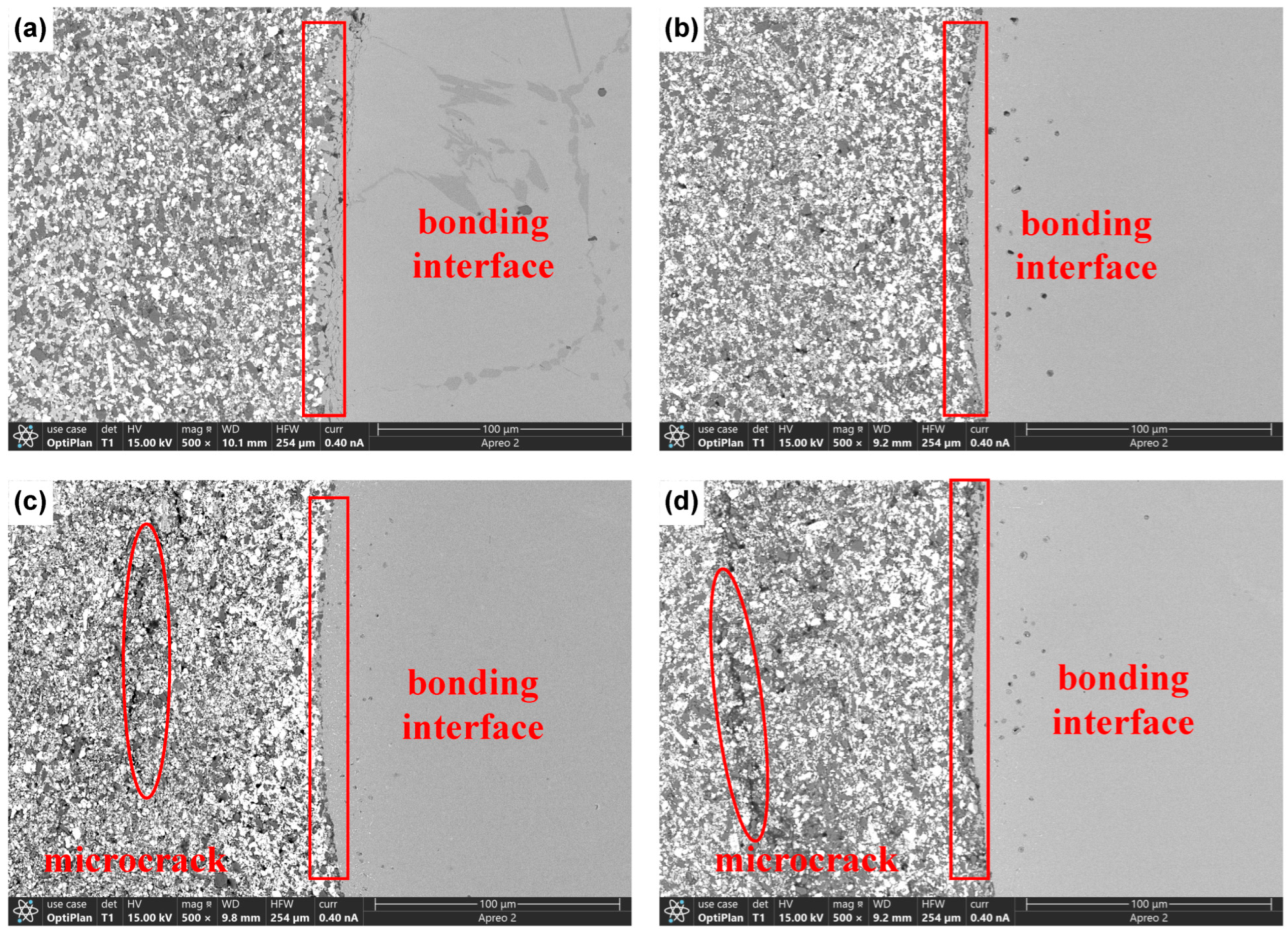
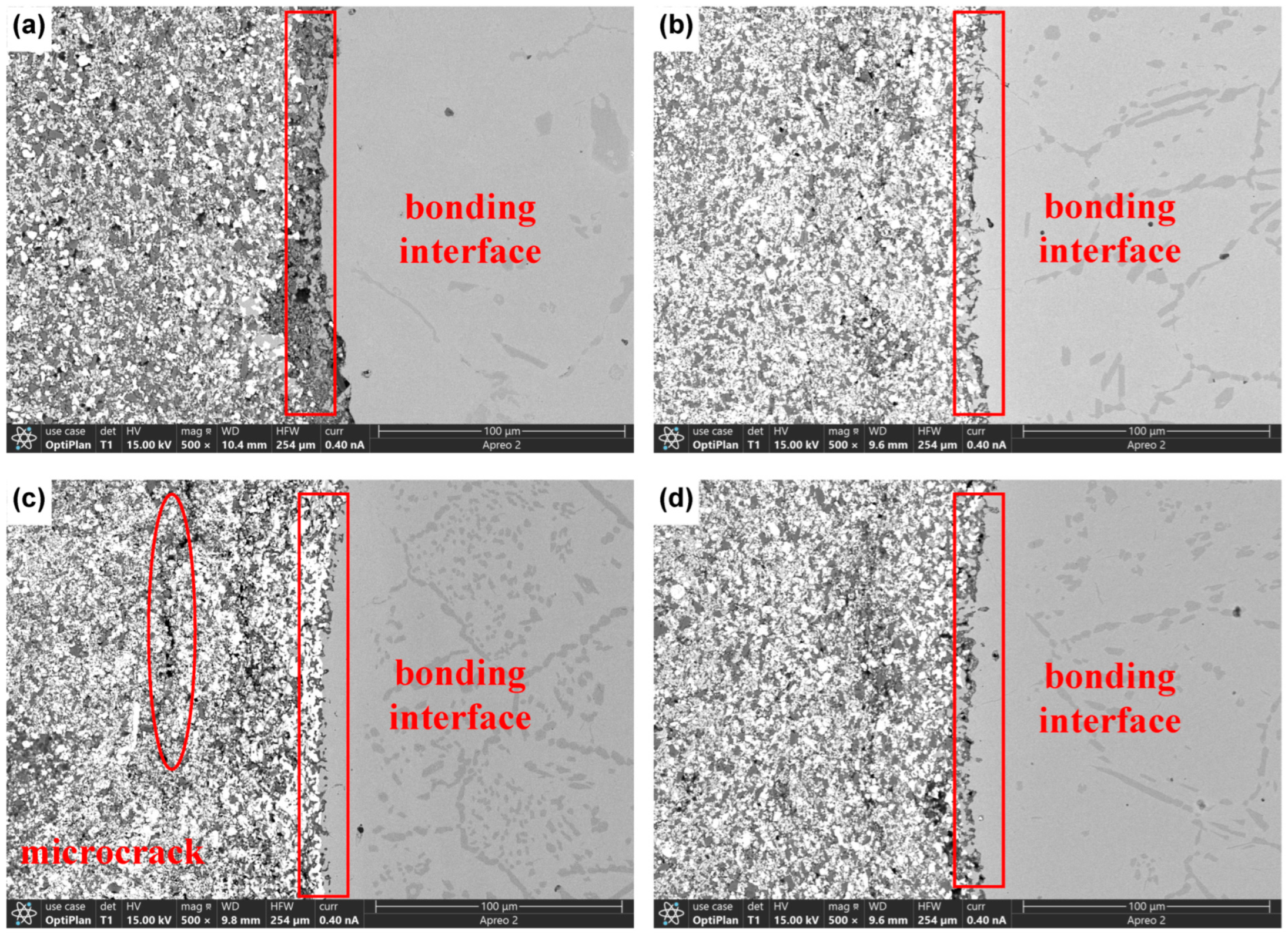
Figure 11 shows the composite interface of WC-Co-TiC/304 stainless steel composite with different WC content when the Co/TiC content ratio is 3:2. When the WC content is 50%, the composite effect of WC-Co-TiC cemented carbide and 304 stainless steel is not good, and faults occur. At the same time, many holes appear at the side of WC-Co-TiC cemented carbide. When the WC content is 60%, a transition layer appears at the composite interface between WC-Co-TiC cemented carbide and 304 stainless steel, and the composite effect is the best compared with other WC contents. When the WC content is 70%, the WC-Co-TiC cemented carbide and 304 stainless steel composite effect is significant, and there is an obvious transition layer, but the WC-Co-TiC cemented carbide has a long crack. When the WC content is 80%, the composite interface transition layer of WC-Co-TiC/304 stainless steel composite is almost the same as that of 70%, but there are small holes on the side of WC-Co-TiC cemented carbide. Therefore, with the increase of WC content, the composite interface effect of WC-Co-TiC/304 stainless steel composite gradually becomes better, but the side defects of WC-Co-TiC cemented carbide increase. Com-pared with other materials, the composite effect is best when the WC content is 60%. For the high content of WC, cracks only occur near 304 stainless steel, because WC-Co-TiC cemented carbide is closer to the combination of 304 stainless steel, and there are physical property differences between die steel and 304 stainless steel, such as linear expansion coefficient, that also affect the generation of microcracks.
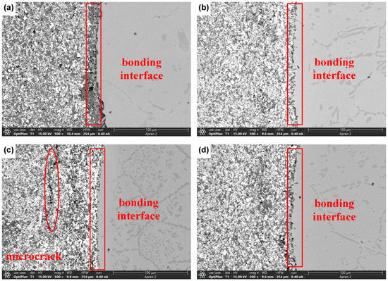
Figure 11.
SEM image of composite interface of WC-Co-TiC/304 stainless steel composite of B series: (a) 50% WC; (b) 60% WC; (c) 70% WC; (d) 80% WC.
3.3. Other Characterization Results of Co/TiC (1:1) and (3:2) WC-CO-TiC/304 Stainless Steel Composites at 60% WC
Through the above comparison between A series and B series, it is known that in A series, the comprehensive effect is the best when the WC content is 60% (1:1), and in B series, the comprehensive effect is the best when the WC content is 60% (3:2). We will compare the WC content of 60% (1:1) and 60% (3:2) in the next step and will use hardness and element diffusion analysis to get the best material ratio.
3.3.1. Comparison of Hardness Results of WC-Co-TiC/304 Stainless Steel Composite
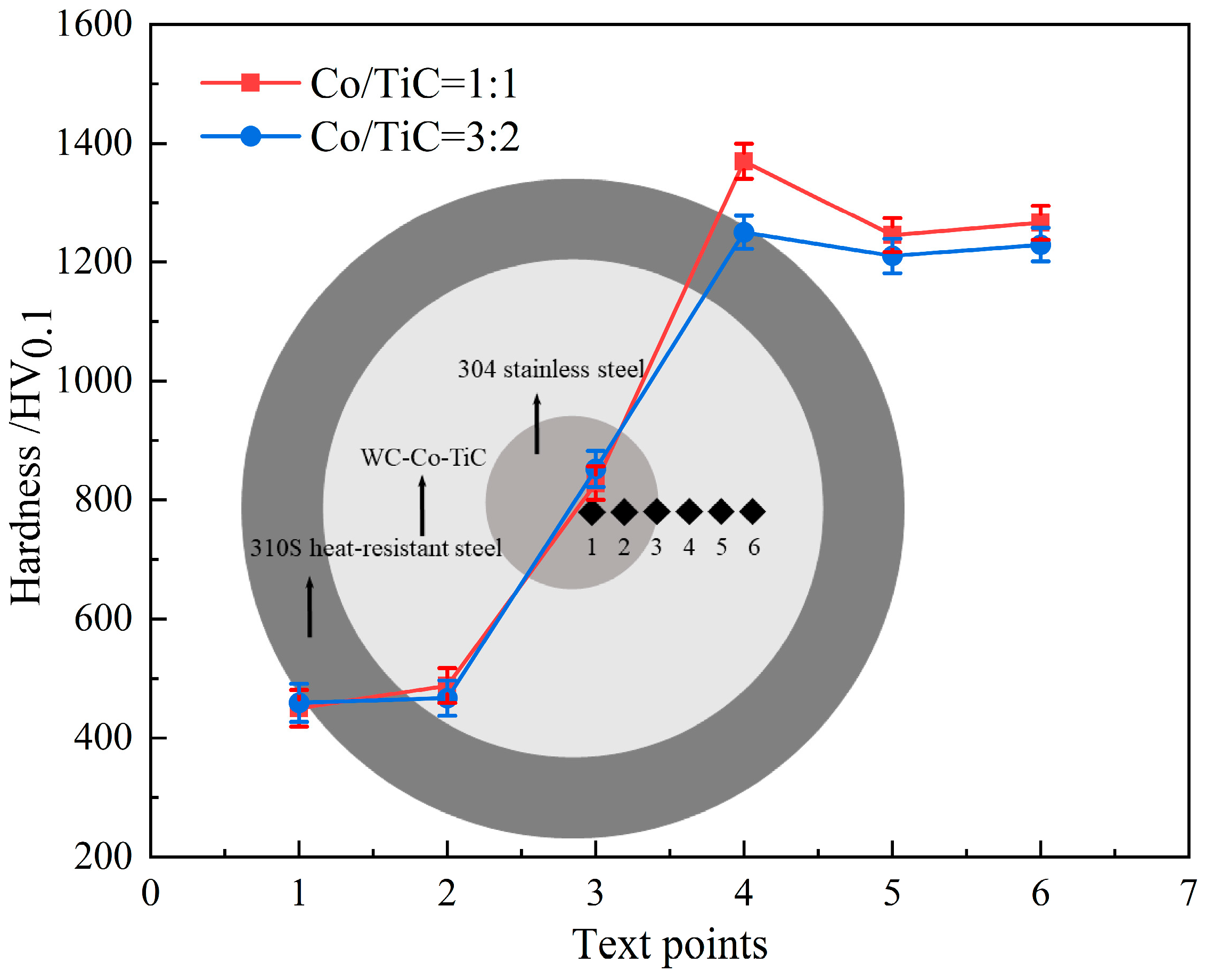
In order to compare the influence of WC content of 60% (1:1) and 60% (3:2) on the microhardness of WC-Co-TiC/304 stainless steel composite, the Vickers hardness of the composite was tested. Figure 12 shows the distribution image of the measured points. Six points are taken from the center of the steel core along the radial direction for measurement. The average value is taken for three measurements of the position of each point. The Vickers hardness distributions of 60% (1:1) and 60% (3:2) are shown in Figure 12.
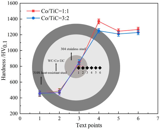
Figure 12.
Hardness measurement points and hardness value image of Co/TiC = 1:1 and Co/TiC = 3:2.
We find that the hardness of 304 stainless steel in the core has little change, and its average hardness value is about 456 HV0.1. The hardness of 60% (1:1) WC content reaches the maximum at point 4, with the maximum value being 1370 HV0.1. Similarly, at 60% (3:2) hardness reaches the maximum at 4, with the maximum value being 1251 HV0.1. This is because the increase of Co content decreases the density of WC-Co-TiC cemented carbide. Later, with the increase of distance, the hardness values decreased at 5 and 6. To sum up, when the WC content is 60% (1:1), the hardness reaches the maximum at 4 and then decreases slightly at 5 and 6.
3.3.2. Comparison of Element Diffusion at Composite Interface of WC-Co-TiC/304 Stainless Steel Composite
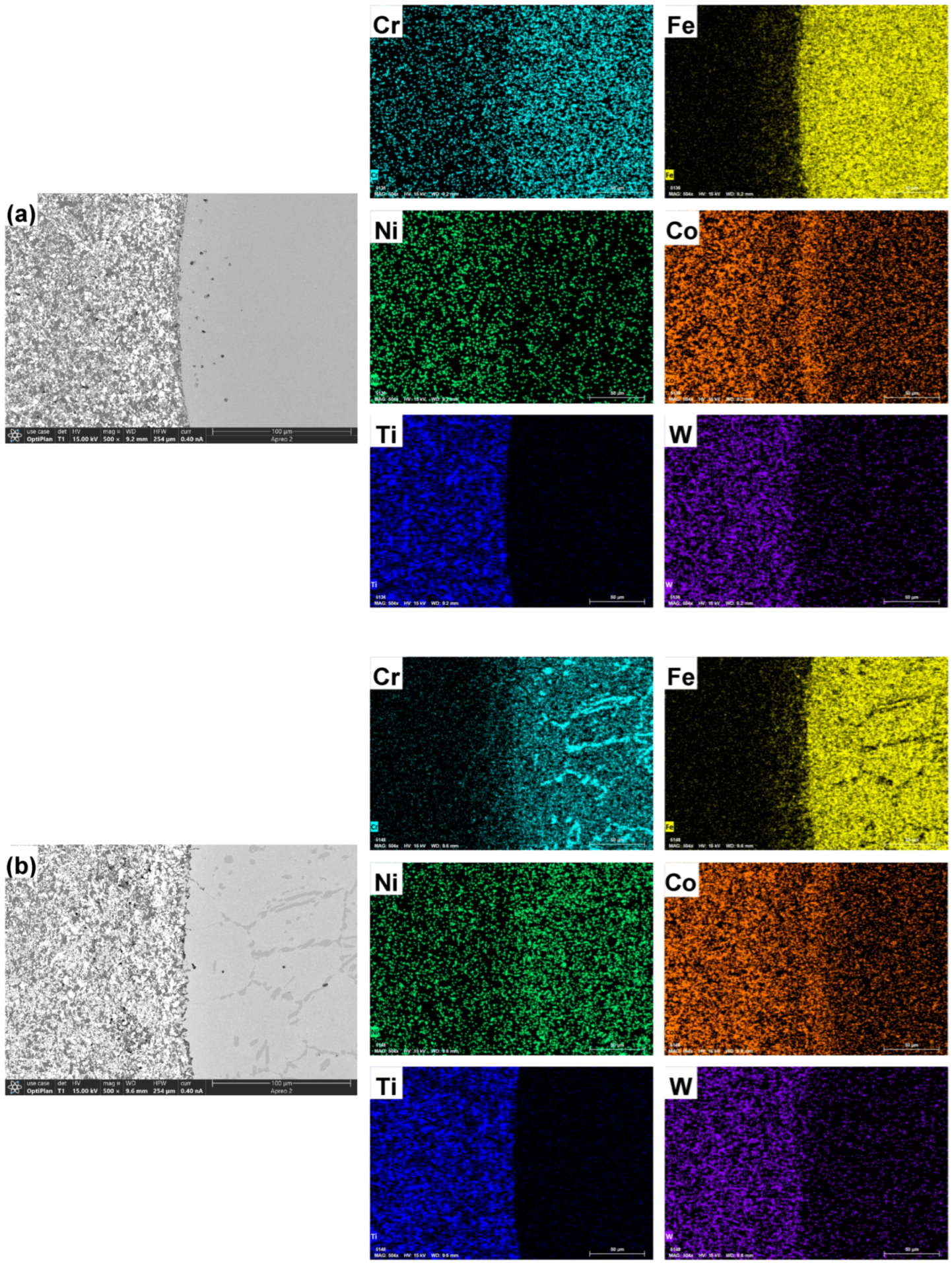
Figure 13a,b shows the element distribution image of WC-Co-TiC/304 stainless steel composite under A2 [60% (1:1)] and B2 [60% (3:2)]. Observe the element distribution image. Cr, Ni, and Co are uniformly distributed in each area at each WC content and concentrated in the interface bonding transition layer. Fe exists widely in the 304 stainless steel area and is also obviously distributed in the interface bonding transition layer under each particle size, while the content in the WC-Co-TiC area is less. The results of the W element are contrary to those of the Cr element and the Fe element, and the Ti element is concentrated in the WC-Co-TiC region at each WC content and nearly has no diffusion in the 304 stainless steel region.

Figure 13.
Element distribution image of WC-Co-TiC/304 stainless steel composite interface (EDS): (a) Co/TiC = 1:1; (b) Co/TiC = 3:2.
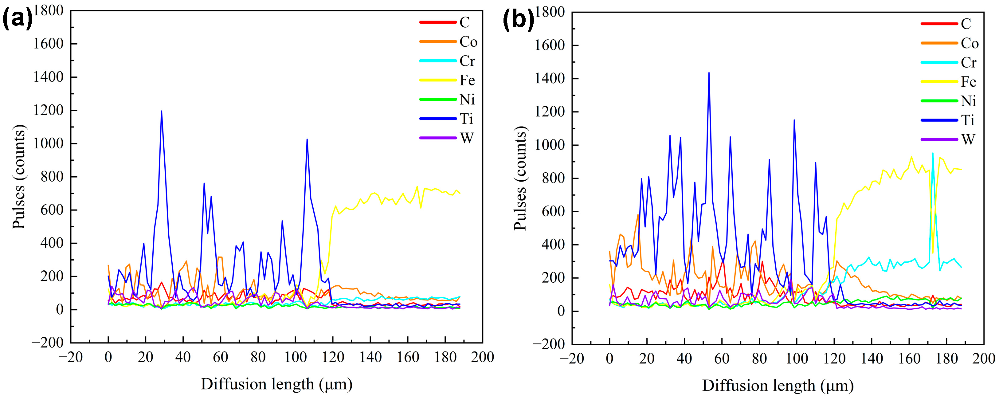
Figure 14a,b shows the linear scanning image of the composite interface of WC-Co-TiC/304 stainless steel composite under A2 [60% (1:1)] and B2 [60% (3:2)], the arrow direction is the test direction, respectively, and the corresponding element distribution in Figure 15a,b. It can be seen from Figure 15 that the composite interface shows that the peak of C element at the composite site decreases significantly, indicating that there is a large amount of C element at the composite site with less diffusion, and most of the C elements exist in the WC-Co-TiC cemented carbide area. The Co element exists in the area of WC-Co-TiC cemented carbide, and a small amount exists in the area of 304 stainless steel, with less diffusion. The Cr and Fe elements diffuse from the 304 stainless steel area to the WC-Co-TiC cemented carbide area. With the increase of diffusion distance, the content of Cr and Fe elements decreases. A small amount of Ni exists in the area of WC-Co-TiC cemented carbide and 304 stainless steel, and there is no obvious diffusion phenomenon. The Ti element peak at the composite site drops obviously, indicating that a large number of Ti elements at the composite site diffuse less. Most of the Ti elements exist in the WC-Co-TiC cemented carbide area, and the diffusion of Ti elements to the 304 stainless steel area is not obvious, which may be caused by the high atomic mass of Ti. The W content in the 304 stainless steel area did not increase significantly, and the diffusion of W element was not obvious.
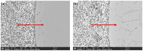
Figure 14.
Line scan image of WC-Co-TiC/304 stainless steel composite interface elements: (a) Co/TiC = 1:1; (b) Co/TiC = 3:2.
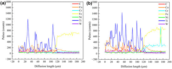
Figure 15.
Line scan element image at interface of WC-Co-TiC/304 stainless steel composite: (a) Co/TiC = 1:1; (b) Co/TiC = 3:2.
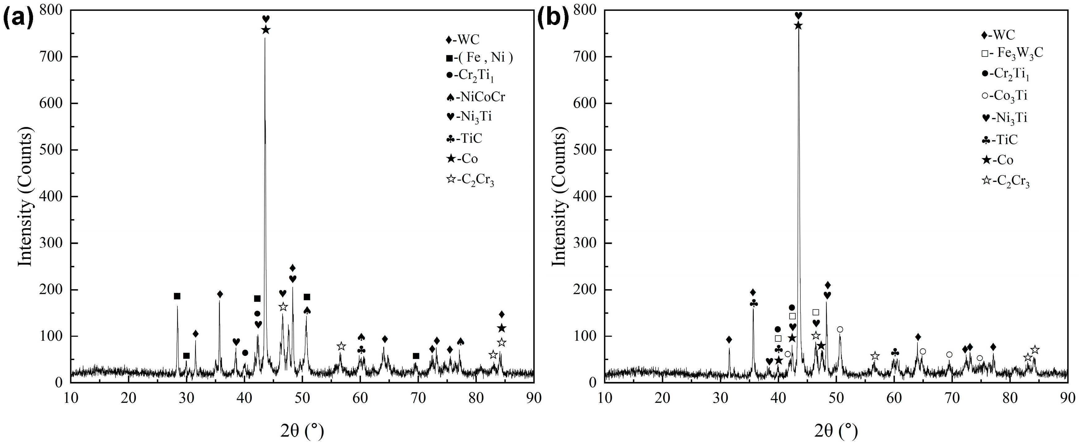
Figure 16a,b shows phase analysis results at the interface of WC-Co-TiC/304 stainless steel composite. The original phase composition of WC, Co, TiC, and (Fe, Ni) at the composite interface was obtained by X-ray diffraction analysis of WC-Co-TiC/304 stainless steel composite through Highscore software, and new phases such as Cr2Ti3, NiCoCr, Ni3Ti,Co3Ti, Fe3W3C, and C2Cr3 were also produced. The elements Cr and Ni in 304 stainless steel diffuse to Co in cemented carbide, and the bonding interface between them is difficult to distinguish, which proves the possibility of their combination. In addition to the composite’s own organizational structure, a new phase has emerged that affects the overall performance.
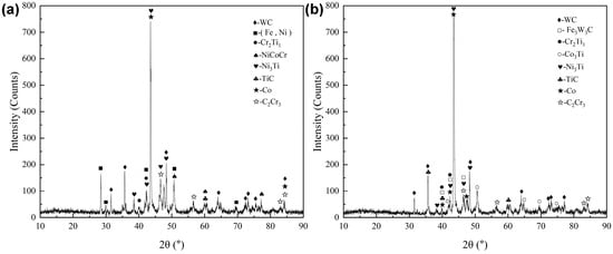
Figure 16.
Phase analysis results at interface of WC-Co-TiC/304 stainless steel composite: (a) Co/TiC = 1:1; (b) Co/TiC = 3:2.
4. Conclusions
- 1.
- In the A series, A2 (WC = 60%), compared with other WC contents, each structure is more uniform and fine, and the agglomeration of each structure is not obvious. The bonding effect of WC-Co-TiC cemented carbide and 304 stainless steel composite interface is the best. With the increase of WC content, the side defects of WC-Co-TiC cemented carbide increase gradually. In the B series, B3 (WC = 70%) and B4 (WC = 80%), compared with other WC contents, have more uniform distribution of each structure, while B2 (WC = 60%) has the best bonding effect at the composite interface of WC-Co-TiC cemented carbide and 304 stainless steel.
- 2.
- Among different WC contents, when the WC content is 60% and the ratio of Co to TiC is 1:1, the density and particle size are the best. In the A series, the density of A2 is 94.45% and the particle size of 0.2–0.3 μm is 38.9%. In the B series, the density of B2 is 92.33%, and the particle size of 0.2–0.3 μm is 38.0%.
- 3.
- Among different WC contents, the hardness and element diffusion uniformity are the best when the WC content is 60% and the ratio of Co to TiC is 1:1. In the hardness comparison, A2 is generally 20–40 HV0.1 higher than B2, but B2 is better at the junction of WC-Co-TiC cemented carbide and 304 stainless steel. In the element diffusion of composite interface, A2 diffuses more evenly on Cr than B2 and has little difference on other elements.
Author Contributions
Writing, original draft preparation, R.Z.; Conceptualization, H.Z., J.W. and Z.J.; investigation, H.L.; writing, review and editing, J.L.; methodology, Y.Z.; supervision, Z.Z. All authors have read and agreed to the published version of the manuscript.
Funding
This research was funded by the National Natural Science Foundation of China (NSFC, No. 52274338) and the Education Department Foundation of Liaoning Province (Grant No. LJKZ0303).
Data Availability Statement
Not applicable.
Conflicts of Interest
The authors declare no conflict of interest.
References
- Bharath, K.N.; Madhu, P.; Thyavihalli, G.Y.; Verma, A.; Sanjay, M.R.; Siengchin, S. A novel approach for development of printed circuit board from biofiber based composites. Polym. Compos. 2020, 41, 11. [Google Scholar] [CrossRef]
- Krishna, U.B.G.; Ranganatha, P.; Rajesh, G.L.; Auradi, V.; Kumar, S.M.; Vasudeva, B. Studies on dry sliding wear characteristics of cermet WC-Co particulate reinforced Al7075 metal matrix composite. Mater. Today Proc. 2019, 16, 343–350. [Google Scholar] [CrossRef]
- Yang, X.H.; Wang, K.F.; Chou, K.C.; Zhang, G.H. Preparation of low binder WC-Co-Ni cemented carbides with fine WC grains and homogeneous distribution of Co/Ni. Mater. Today Commun. 2022, 30, 103081. [Google Scholar] [CrossRef]
- Fernandes, C.M.; Rocha, A.; Cardoso, J.P.; Bastos, A.C.; Soares, E.; Sacramento, J.; Ferreira, M.G.S.; Senos, A.M.R. WC-stainless steel hardmetals. Int. J. Refract. Metals Hard 2018, 72, 21–26. [Google Scholar] [CrossRef]
- Cheniti, B.; Belkessa, B.; Maamache, B.; Ouali, N.; Sedlák, R.; Hvizdoš, P.; Boutaghou, Z. Effect of WC-Co cermet positioning and NiCr interlayer on the microstructure and mechanical response of the dissimilar WC-Co/AISI 304 L rotary friction joint. Int. J. Refract. Metals Hard 2021, 101, 105653. [Google Scholar] [CrossRef]
- Soria, B.T.; Lozada, C.L.; Ibarreta, L.F.; Martinez, R.P.; Sanchez, J.M.M. Effect of chromium and carbon contents on the sintering of WC-Fe-Ni-Co-Cr multicomponent alloys. Int. J. Refract. Metals Hard 2020, 92, 105317. [Google Scholar] [CrossRef]
- Najar, K.A.; Butt, M.M. RETRACTED: Development of a dual-layered diamond-coated WC–Co cutting tool for enhancing tool life in the dry machining of mild-steel alloy. Proc. Inst. Mech. Eng. A-J. Powder Part B J. Eng. Manuf. 2019, 233, 1515–1528. [Google Scholar] [CrossRef]
- Hasan, M.; Zhao, J.; Jia, F.; Wu, H.; Ahmad, F.; Huang, Z.Y. Optimisation of sintering parameters for bonding nanocrystalline cemented tungsten carbide powder and solid high strength steel. Compos. Interface 2021, 28, 477–492. [Google Scholar] [CrossRef]
- Yang, Q.M.; Yang, J.G.; Wei, S.U.; Chen, L.Y.; Chen, H.; Guo, S.D. Research Progress of Nano/Ultrafine WC-Co Cemented Carbides. Rare Metals Cem. Carbides 2020, 34, 15138–15144. (In Chinese) [Google Scholar]
- Cheniti, B.; Miroud, D.; Badji, R.; Hvizdoš, P.; Fides, M.; Csanádi, T.; Belkessa, B.; Tata, M. Microstructure and mechanical behavior of dissimilar AISI 304L/WC-Co cermet rotary friction welds. Mater. Sci. Eng. 2019, 758, 36–46. [Google Scholar] [CrossRef]
- Luo, R.; Xiong, H.W.; Chen, N.; Li, Z.Y. Effect of carbon content on microstructure and properties of WC-TiC-Co alloy. Mater. Sci. Eng. Powder Met. 2021, 25, 381–388. (In Chinese) [Google Scholar]
- Tang, Y.; Chen, L.; Yang, Q.; Zhong, Z.Q.; Xu, G.Z. Effect of a slight change in carbon content near the upper/lower limit on the microstructure and mechanical properties of WC-10Co cemented carbides. Int. J. Refract. Metals Hard 2021, 96, 105465. [Google Scholar] [CrossRef]


Disclaimer/Publisher’s Note: The statements, opinions and data contained in all publications are solely those of the individual author(s) and contributor(s) and not of MDPI and/or the editor(s). MDPI and/or the editor(s) disclaim responsibility for any injury to people or property resulting from any ideas, methods, instructions or products referred to in the content. |
© 2023 by the authors. Licensee MDPI, Basel, Switzerland. This article is an open access article distributed under the terms and conditions of the Creative Commons Attribution (CC BY) license (https://creativecommons.org/licenses/by/4.0/).