Abstract
The back-up rolls of hot strip mills wear considerably under the conditions of high temperature and heavy load, which affects the roll service period and the stability of strip profile control. Serious uneven wear, short service periods, and spalling problems occurred on conventional back-up rolls of upstream stand CVC mills in 1500 mm continuous hot rolling production lines. Through finite element simulations, the problems are determined to be caused by the configuration of a flat roll contour of the back-up roll and the CVC roll contour of the work roll, which leads to uneven contact pressure between the rolls. The wear distribution form is ‘anti-CVC’ shape, and there is peak contact pressure between the rolls on both sides of the roll body. In particular, the long-term negative shifting of CVC on site further increases the peak contact pressure between the rolls, resulting in uneven wear and spalling accident. Based on the design technology of VCR back-up roll contours with variable contact lengths, and considering the cooperation between the middle of the back-up roll and the CVC work roll contour, the roll contour of the back-up roll has been improved. The designed VCRplus roll contour was analyzed and evaluated by finite element simulation, including the distribution of contact pressure between rolls, the control effect of bending force, and the transverse stiffness of the roll gap. The simulation results show that the VCRplus roll contour can effectively improve the uneven distribution of contact pressure between the rolls, and effectively improve the control effect of bending force and the transverse stiffness of the roll gap. Industrial tests demonstrate that VCRplus back-up roll contours have the advantages of uniform back-up roll wear, enhanced self-sustaining of the roll contour, and further extension of the back-up roll service life. The roll contour has now stably been put into industrial production, and the rolling capacity during the back-up roll service period has been extended from 150,000,000 kg to 250,000,000 kg.
1. Introduction
Hot strip mills work under conditions of high temperature and heavy load. Due to the long service time, the back-up rolls of the mill will wear seriously, which will affect the service period of the rolls and the stability of the strip profile control. In particular, the axial uneven wear of the back-up roll in CVC mills is serious; therefore, self-sustaining of the roll contour is poor, due to the coupling relationship between the roll deflection and the roll contour, which will adversely affect the strip profile control. In addition, long-term excessive contact pressure between the rolls somewhere in the roll makes spalling easy to occur [1,2,3,4,5].
A reasonable back-up roll contour design can improve the contact pressure distribution between the back-up roll and the work roll, and effectively improve the uneven wear of the back-up roll [6,7]. In addition, this area, called the ‘harmful contact area’, where the length of the contact line between the work roll and the back-up roll exceeds the width of the strip, is one of the main factors affecting the deflection of the roll system. The variable contact back-up roll, the VCR (varying contact roll), a specially designed roll contour, can effectively reduce ‘the harmful contact zone’ and improve the strip profile control ability [8,9]. The VCR technology is introduced into the design of the back-up roll contour of the CVC mill, and the contact pressure distribution between the back-up roll and work roll is considered comprehensively, which can improve the initial strip profile control ability of the mill and the stability of the strip profile control during the service period of the back-up rolls [10,11,12].
Li et al. [13] proposed a novel back-up roll contour for CVC mills in the form of a central CVC for the wear characteristics of the back-up rolls in CSP production lines, and proved that the new roll contour has good strip profile control ability and is self-sustaining through theoretical analysis and field test. Hao et al. [14] analyzed the problem of uneven wear when the VCR back-up roll contour was matched with the CVC work roll contour, and improved the VCR roll contour. Shao et al. [15] optimized the back-up roll contour of CVC mills in the CSP production line of Maanshan Iron and Steel Co., Ltd., Maanshan, China. And designed a VCRplus back-up roll contour using the conventional VCR roll contour method, superposing the CVC roll contour. They also compared it with the original roll contour, the contact pressure between the rolls, crown adjustment domain, roll gap transverse stiffness, roll bending force control efficiency, and other indicators. Liu et al. [16] further studied the influence of chamfering at both ends of the VCRplus roll on the contact pressure distribution between the rolls, and optimized the chamfering of VCRplus roll. In order to solve the problem of the insufficient utilization of the back-up roll surface in a Hansteel 2250 mm production line, Li et al. [17] flattened the roll contour of the CVC work roll and superimposed chamfering as a new back-up roll contour, which extended the service period of the back-up roll. It can be seen that the back-up roll contour design is of great significance to its working characteristics.
In a 1500 mm continuous hot rolling production line, the finishing mill is a seven-stand four-high mill. The upstream stand is a CVC mill. The contour of the back-up roll is flat with a chamfer at the edge. Additionally, the service period of the back-up roll is short. The rolling capacity during the service period is approximately 150,000,000 kg, which will yield cross-use of the back-up rolls of different service periods, exerting a certain pressure on the stability of production, as well as occasional spalling problems. In this study, based on finite element simulation, the contact pressure distribution between the rolls at the existing roll contour configuration was analyzed, and the improvements of the back-up roll contours were applied to improve the service life of the rolls.
2. Wear and Spalling of 1500 mm CVC Mill’s Back-Up Roll
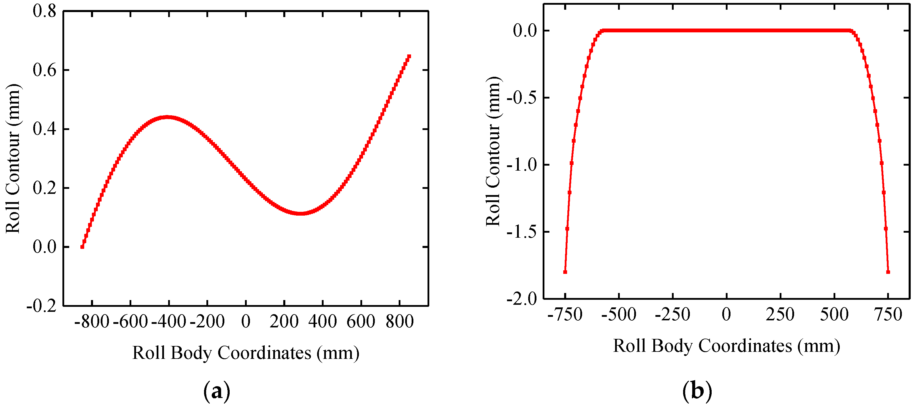
The F1~F4 stand of a 1500 mm rolling mill adopts a four-high CVC model. The work roll contour is shown in Figure 1a, and the back-up roll adopts the conventional flat roll and edge chamfering, as shown in Figure 1b. The work roll contour is quintic CVC, as shown in Equation (1). The chamfering of the back-up roll is in the form of an arc, with a length of 180 mm and a depth of 1.8 mm.
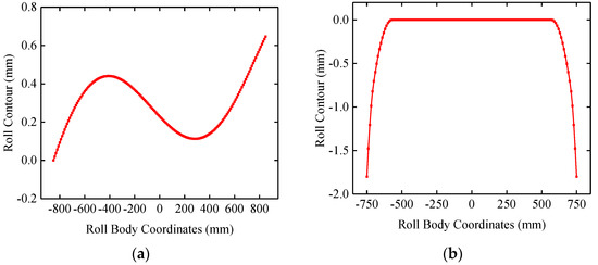
Figure 1.
(a) Work roll contour; (b) original back-up roll contour.
In Equation (1), x is the coordinate of the roll body, and its origin is at the midpoint of the roll body (mm); w(x) is the quintic CVC roll contour equation; a1~a5 is the coefficient.
In production sites, to track the measurement of the back-up roll contour when its service expires, the contour is only measured on the grinder on 930 mm, leaving 285 mm unmeasured on either side. The roll contour curve is shown in Figure 2. It can be seen that the worn roll contour of the back-up roll is affected by the work roll contour with an ‘anti-CVC shape’ and poor self-sustaining ability.
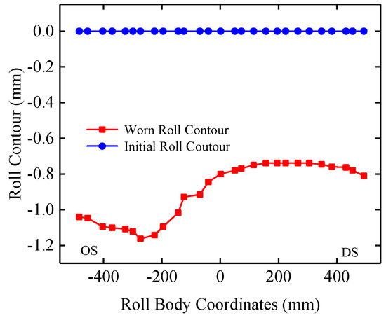
Figure 2.
Typical worn roll contour of back-up roll.
During the worn roll contour tracking process, a spalling accident occurred on the upper back-up roll at the F2 stand. As shown in Figure 3, the spall center is located about 150 mm away from the drive side. Spalling occurs when wear is severe.
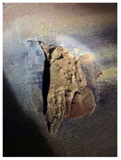
Figure 3.
Back-up roll surface spalling.
3. Establishment of Finite Element Model of a 1500 mm Four-High Mill
Finite element simulation is an effective method to solve the force and deformation of the roll system [18,19,20]. In order to analyze the contact pressure distribution and strip profile control characteristics of the CVC mill, the elastic–plastic coupling simulation model of the system-strip roll was established, as shown in Figure 4a. The basic parameters of the simulation model are shown in Table 1.
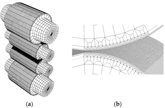
Figure 4.
(a) Finite element simulation model; (b) zone of contact.

Table 1.
Simulation model parameters.
The characteristics of the model are as follows:
- (1)
- The roll is an elastic body; the strip is an elastic-plastic body;
- (2)
- The roll contour can be entered according to the actual needs of different roll contours. In this study, considering the dynamic change process of the thermal crown of the work roll during the rolling process, the influence of the thermal roll contour is ignored;
- (3)
- The simulation calculation process is divided into three analysis steps. The first step ensures contact between the rolls, the roll and the strip. The second step loads the rolling force and the bending force, and the third analysis step is the rolling process;
- (4)
- Except for the roll axis, the element types are all eight-node linear hexahedral elements, and the roll axis is set to six-node mother triangular prism element due to geometric constraints. In order to account for the accuracy of the calculation results and the calculation time consumption, the elements are only subdivided in the contact area, as shown in Figure 4b. This subdivision method not only reduces the number of elements, but also avoids the use of non-hexahedral elements, and the accuracy of the calculation results can be guaranteed.
The simulation model is used to calculate the contact pressure between the rolls, so as to optimize the back-up roll contour. The strip profile of the loaded roll gap can be obtained to study the strip profile control characteristics.
4. Analysis of the Contact Pressure between the Rolls
The contact pressure distribution between the rolls was calculated at different strip widths, B, unit width rolling forces, q, and work roll shifting positions, S; the unilateral bending force was 500 kN.
In order to quantitatively describe the non-uniformity of the contact pressure between the rolls, the non-uniformity coefficient K of the contact pressure between the rolls is defined, as shown in Equation (2).
In Equation (2), Pmax is the maximum value of the contact pressure between the rolls; Pa is the average value of the contact pressure between the rolls. The larger the coefficient of K, the more uneven the contact pressure between the rolls.
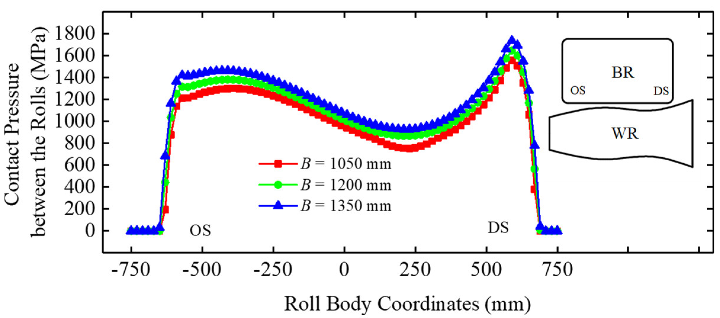
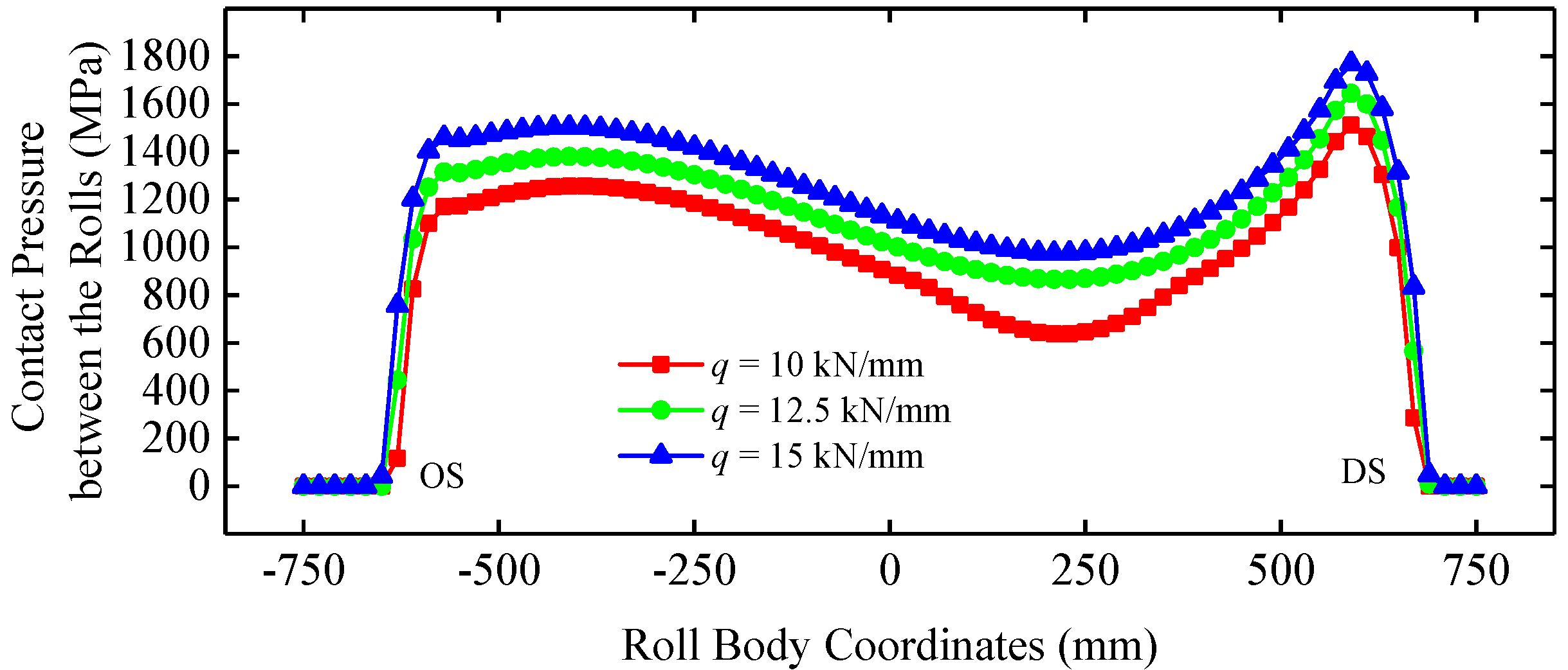
It can be seen from Figure 5 and Figure 6 that the distribution of the contact pressure between the rolls is basically the same. The distribution of the contact pressure between rolls in the middle of the roll is ‘anti-CVC shape’, which proves that the work roll contour presents a decisive influence on the contact pressure between the rolls. The maximum value of the contact pressure between the rolls is near 150 mm from the roll edge. Especially, the contact pressure peak between the rolls at 150 mm from the drive side is obvious, corresponding to the spalling position of the back-up roll. The length of the contact area between the rolls at different widths is almost unchanged. It can be seen from Table 2 and Table 3 that the average and maximum values of the contact pressure between the rolls increase with the increase in strip width and rolling force. Among them, the larger the rolling force, the smaller the coefficient, K, and the coefficient, K, caused by the change in strip width does not change much.
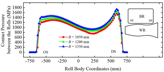
Figure 5.
Contact pressure between the rolls at different strip widths B (S = 0 mm, q = 12.5 kN/mm).

Figure 6.
Contact pressure between the rolls at different rolling forces q (S = 0 mm, B = 1200 mm).
Table 2.
The coefficient K at different strip widths B.
Table 3.
The coefficient K at different rolling forces q.
It can be seen from Figure 7 and Table 4, the roll shifting has a certain influence on the distribution of the contact pressure between the rolls. When the roll shifting is positive, the unevenness of the contact pressure distribution between the rolls and the peak value of the contact pressure between the rolls are improved. When the roll shifting is negative, the unevenness of the contact pressure distribution between the rolls is more obvious, the coefficient K reaches 1.61, and the peak value of the contact pressure between the rolls increases, from S = 100 mm to S = −100 mm, an increase of 21%. As shown in Figure 8, the CVC work roll of F2 stand in the production site is dominated by a negative roll shifting, which aggravates the uneven distribution of the contact pressure between the rolls and increases the peak value of the contact pressure between the rolls. Therefore, the uneven distribution of the contact pressure between the rolls is the main reason for uneven wear of the back-up roll, as shown in Figure 2. The peak value of the contact pressure between the rolls at long-term negative roll shifting is the main reason for the spalling of the back-up roll shown in Figure 3.
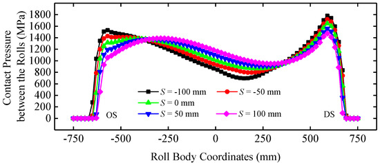
Figure 7.
Contact pressure between the rolls at different roll shifting positions S (B = 1200 mm, q = 12.5 kN/mm).
Table 4.
The coefficient, K, at different roll shifting positions, S.
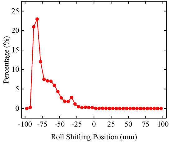
Figure 8.
F2 stand work roll shifting position distribution.
5. VCRplus Back-Up Roll Contour Design
Through the analysis in Section 4, although the contact pressure between the rolls is different under different working conditions, its main form is still determined. Equation (3) is the geometric coordination equation for solving the deflection deformation of four-high mills [21], which can be used to further analyze the uneven contact pressure between the rolls and provide direction for the optimization of back-up roll contour.
In Equation (3), x is the coordinate of the roll body, and its origin is at the midpoint of the roll body (mm); ∆Y(x) is the deflection difference between the work roll and the back-up roll (mm); F(x) is the force between the rolls (kN), which is positively correlated with the contact pressure between the rolls; αF(x) is the absolute value of the variation in the axial distance between the work roll and the back-up roll in the reduction direction caused by the roll flattening (mm), and it is assumed that the force between the rolls is linear with the flattening amount, and the linear coefficient is α (mm/kN); δ(x) is the gap between the rolls, which is determined by the initial roll contour of the back-up roll and the work roll (mm).
The deflection deformation theory of the four-high mill has proven that ∆Y(x) is closer to the edge of the roll body, the larger it is. In the area beyond the strip, the rolling force of the roll system is instantly from there to nothing, which will form an effect similar to the cantilever beam, ‘the harmful contact zone’, which will further cause excessive ∆Y(x). If the larger ∆Y(x) is not adapted and compensated by δ(x), it will lead to a sharp increase in the contact pressure between the rolls, forming a pressure peak, until the edge chamfering of the back-up roll makes δ(x) larger, so that the contact pressure between the rolls can be reduced. This is the reason why the contact pressure between the rolls exhibits a peak and the peak decreases rapidly to 0 MPa in Figure 5, Figure 6, Figure 7 in Section 4. In the case of a certain ∆Y(x), the smaller the δ(x) and the greater the contact pressure between the rolls, which is the reason why the contact pressure between the rolls is distributed in an ‘anti-CVC shape’.
If the back-up roll contour can be designed to enlarge the δ(x) in the ‘harmful contact zone’ and adapt to the change in ∆Y(x), it will weaken the adverse effect of ‘the harmful contact zone’, weaken the contact pressure peak between the rolls, and improve the strip profile control ability. This is the basic concept of the variable contact roller (VCR). At the same time, if δ(x) can offset the influence of roll contour difference, it will weaken the distribution form of the contact pressure between the rolls of ‘anti-CVC shape’, so that the contact pressure between the rolls is uniform.
It is necessary to optimize the back-up roll contour for improving the uneven distribution of the contact pressure between the rolls and further improving the strip profile control ability. A certain proportion of the CVC roll contour is superimposed on the basic VCR roll contour to form the VCRplus roll contour for the 1500 mm CVC roll mill based on the technology of the VCR variable contact backup roll contour (Figure 9). The roll contour can be realized by arc, trigonometric function, polynomial, etc. According to the characteristics of field grinder, the roll contour design is completed in the form of six polynomials.
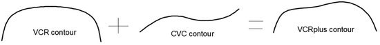
Figure 9.
F2 stand work roll shifting position distribution.
Taking the upper back-up roll as an example, the VCRplus roll contour function is shown in Equation (4):
In Equation (4), x is the coordinate of the roll body, and its origin is at the midpoint of the roll body; h(x) is VCRplus roll contour; w’(x) is the anti-symmetric roll contour of the middle part of the upper work roll with a length of 1500 mm; g(x) is the VCR roll contour (Equation (5)); λ is the coefficient. In order to achieve the effect of uniformize the contact pressure between the rolls and avoid affecting the work roll shifting, λ should satisfy 0 < λ < 1, and the specific value of λ is optimized by finite element simulation, is 0.8.
In Equation (5), b1~b5 is the coefficient.
According to the actual situation of the field and the finite element simulation results, the back-up roll contour is optimized. The final VCRplus roll contour design is shown in Figure 10. The coefficients of VCRplus roll contour in the field grinder are shown in Table 5.
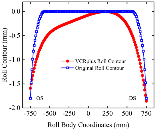
Figure 10.
VCRplus back-up contour.
Table 5.
Coefficients of the VCRplus roll contour.
6. VCRplus Back-Up Roll Contour Evaluation
After the VCRplus roll contour was designed, the contact pressure distribution between the rolls at various working conditions has been calculated and compared with the original back-up roll contour.
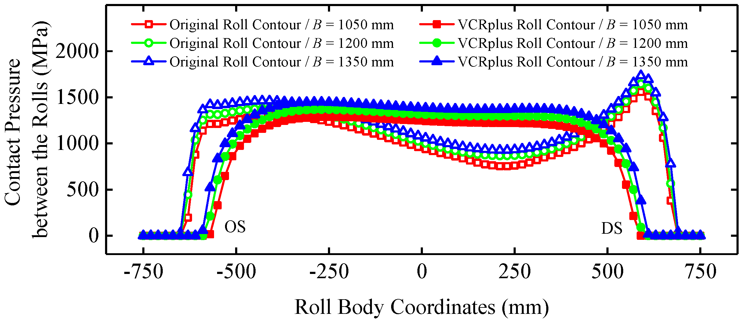
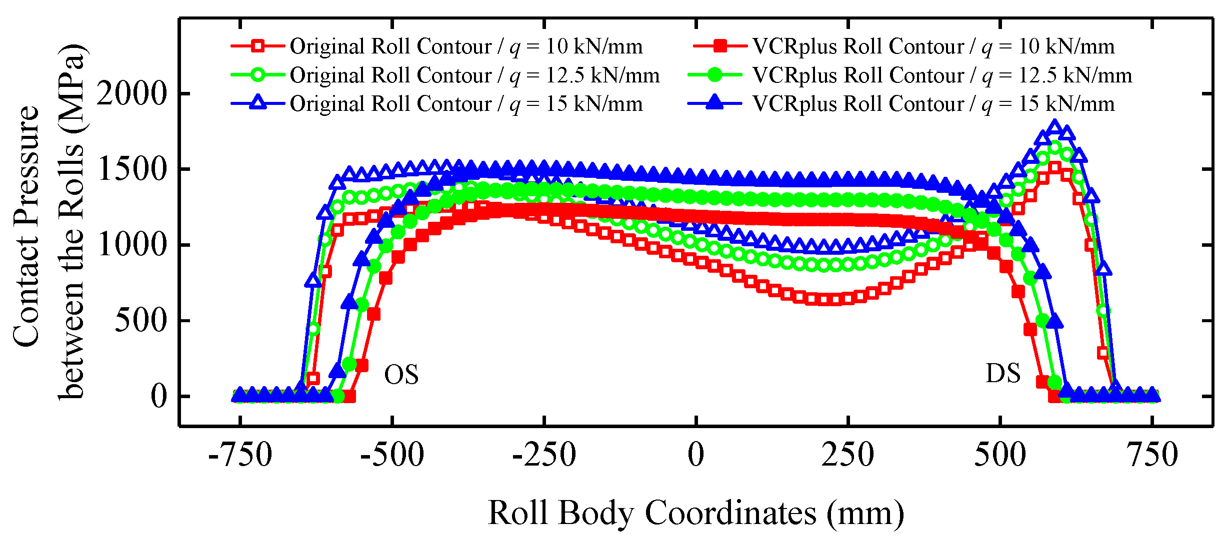
It can be seen from Figure 11 and Figure 12 that after the back-up roll adopts the VCRplus roll contour, the contact pressure between the rolls becomes uniform as a whole, and the peak of the contact pressure between the rolls on both sides of the roll disappears. Due to the VCRplus back-up roll contour added the characteristic of the CVC roll contour, largely counteracts the ‘anti-CVC shape’ contact pressure distribution between the rolls, conducive to uniform wear. It can be seen from Table 6 and Table 7 that the coefficient, K, under the VCRplus roll contour exhibited a significant decrease at each working condition, approximately 21%~25%; the maximum value of the contact pressure between the rolls decreased by approximately 15%~18%. The VCRplus roll contour had a better variable contact performance; therefore, the length of the contact area between the rolls under different widths and different rolling forces changed significantly compared with the original roll contour, which adapted to the change in strip width.

Figure 11.
Comparison of the contact pressure between the rolls at different strip widths B (S = 0 mm, q = 12.5 kN/mm).
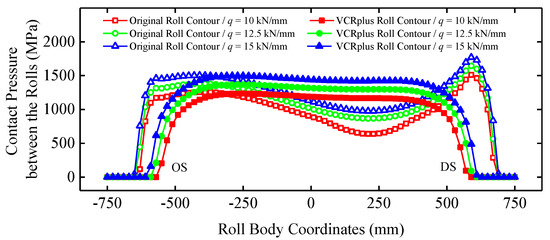
Figure 12.
Comparison of the contact pressure between the rolls at different rolling forces q (S = 0 mm, B = 1200 mm).
Table 6.
The coefficient, K, at different strip widths, B.
Table 7.
The coefficient, K, at different rolling forces, q.
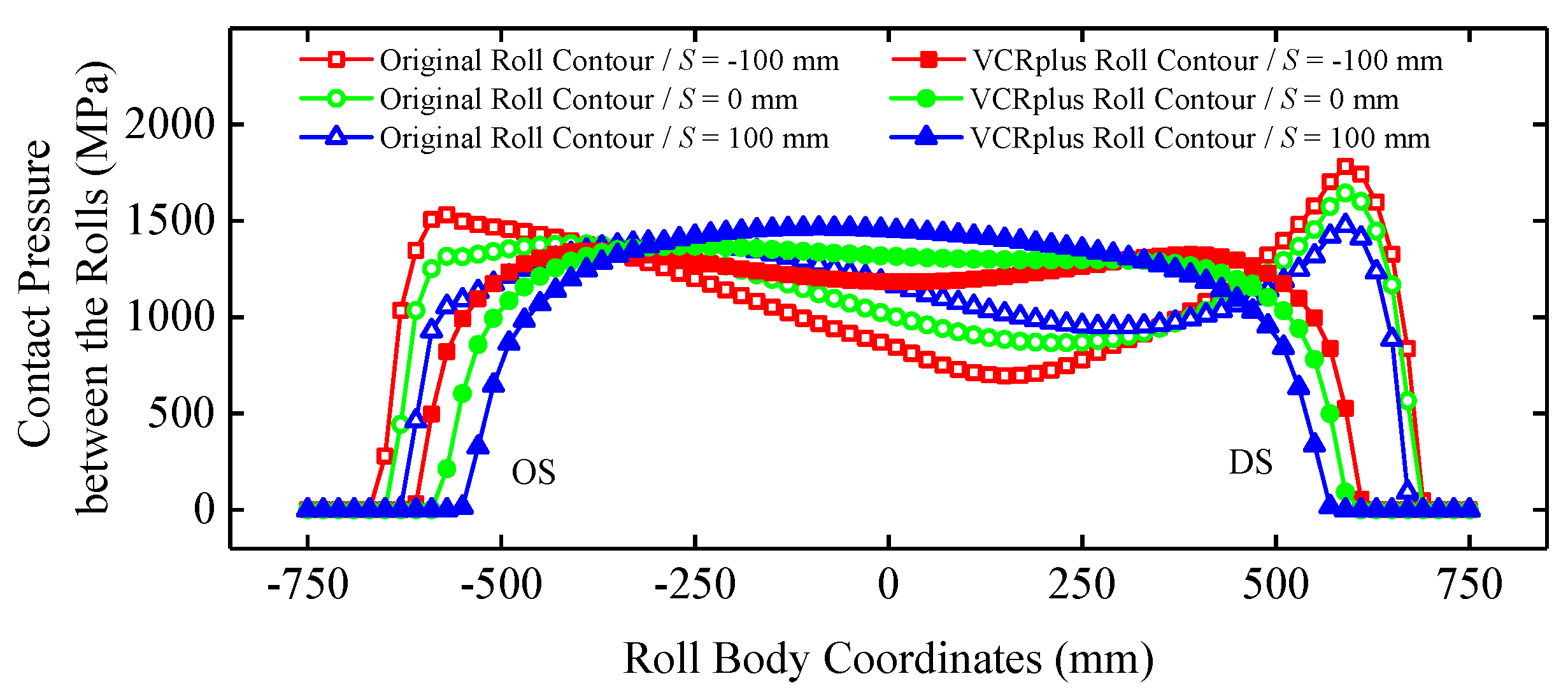
It can be seen from Figure 13 and Table 8 that after the back-up roll adopted the VCRplus roll contour, the peak values of the contact pressure between the rolls at each shifting position decreased significantly, and the whole became uniform. The coefficient, K, no longer changed significantly with the roll shifting position. Especially when S = −100 mm, the peak value of contact pressure between the rolls on the drive side decreased by approximately 33% and the coefficient K decreased by approximately 29%, which no longer showed higher peak values of the contact pressure between the rolls and stronger non-uniformity of the contact pressure between the rolls, which will strongly reduce the probability of spalling accidents and make wear more uniform.

Figure 13.
Comparison of the contact pressure between the rolls at different roll shifting positions, S, (B = 1200 mm, q = 12.5 kN/mm).
Table 8.
The coefficient, K, at different roll shifting positions, S.
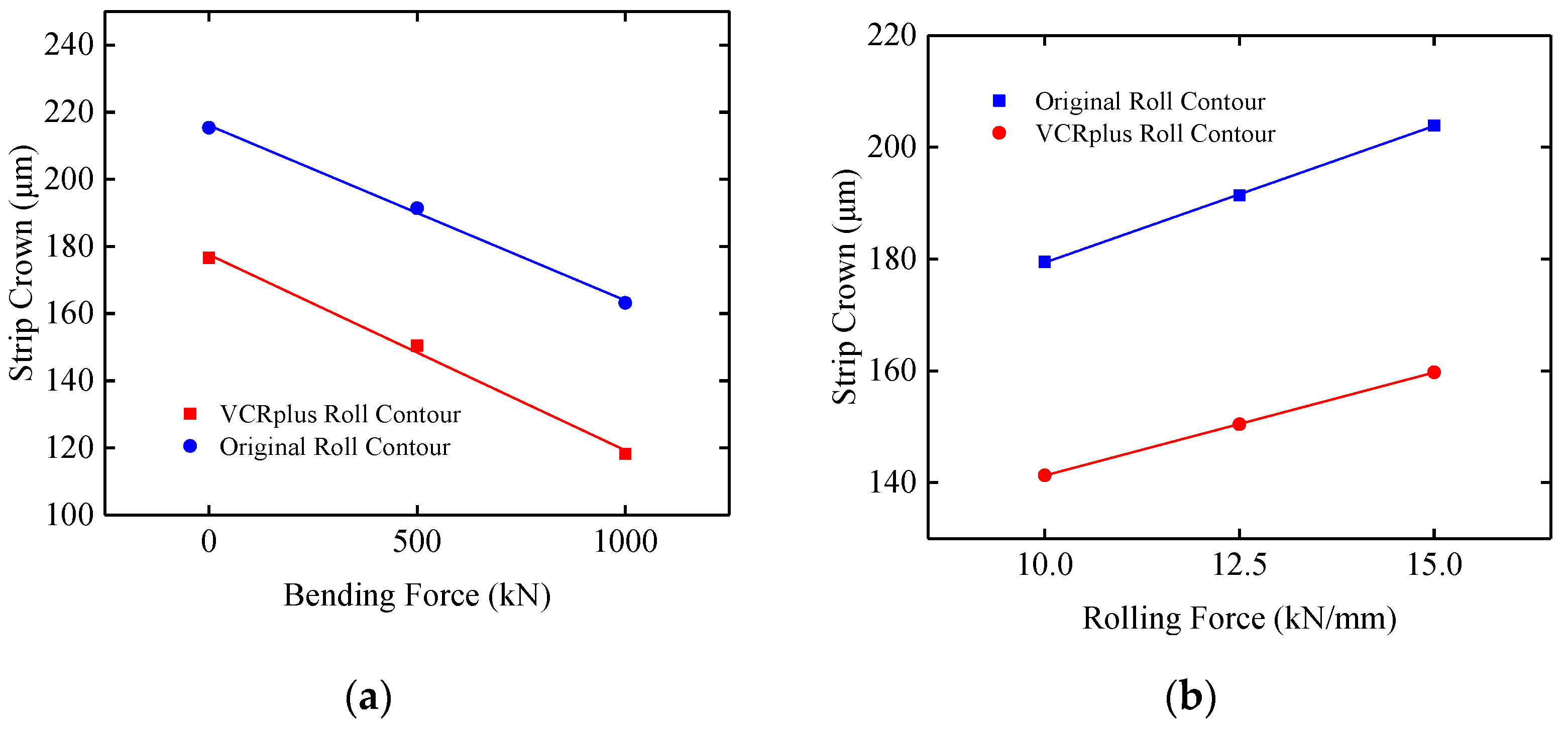
The strip profile control ability of the VCRplus back-up roll contour and the original back-up roll contour is further compared and analyzed by calculating the strip crown with different unilateral bending forces and unit width rolling forces, as shown in Figure 14. Compared with the original roll contour, the bending force control effect of VCRplus roll contour is increased by 11.8%, and the transverse stiffness of the roll gap is increased by 32.2%. The strip profile control ability and the stability are clearly improved.
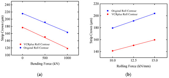
Figure 14.
(a) Bending force control effect; (b) roll gap transverse stiffness.
7. VCRplus Back-Up Roll Contour Application
After completing the design and theoretical evaluation of the VCRplus back-up roll contour, the roll contour coefficients (Table 5) were input in the field roll grinder, and the grinding was guided to ensure accurate grinding of the VCRplus roll contour.
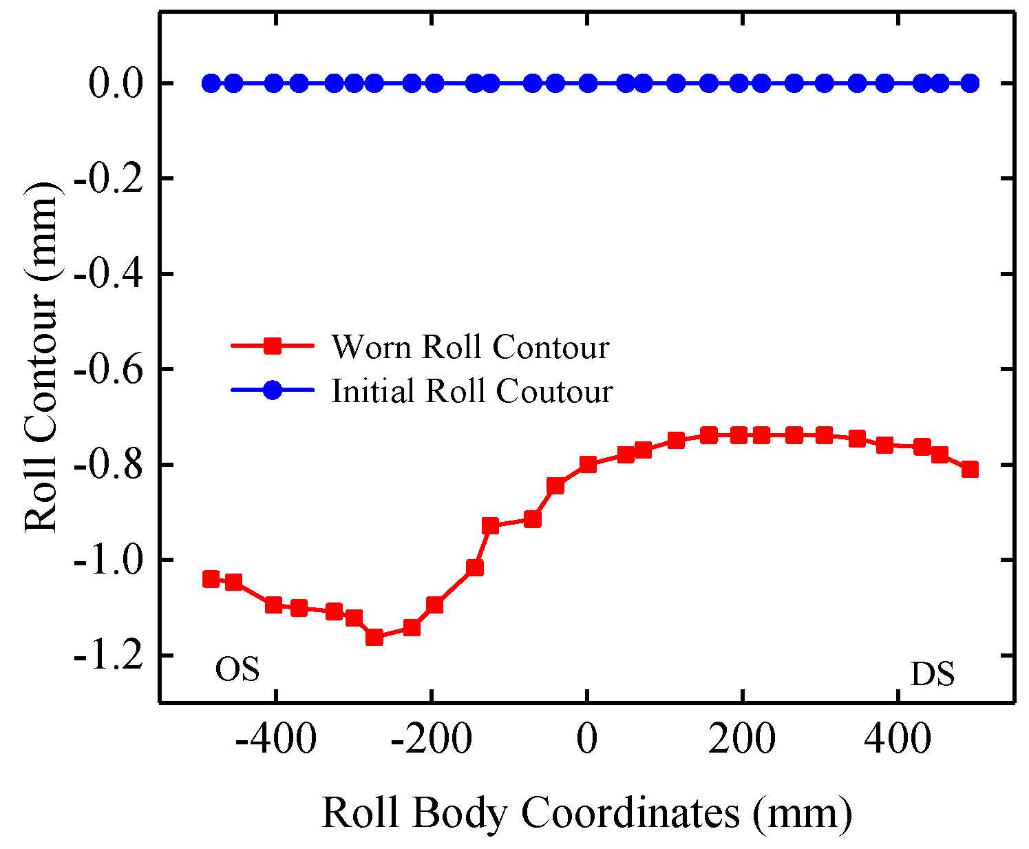
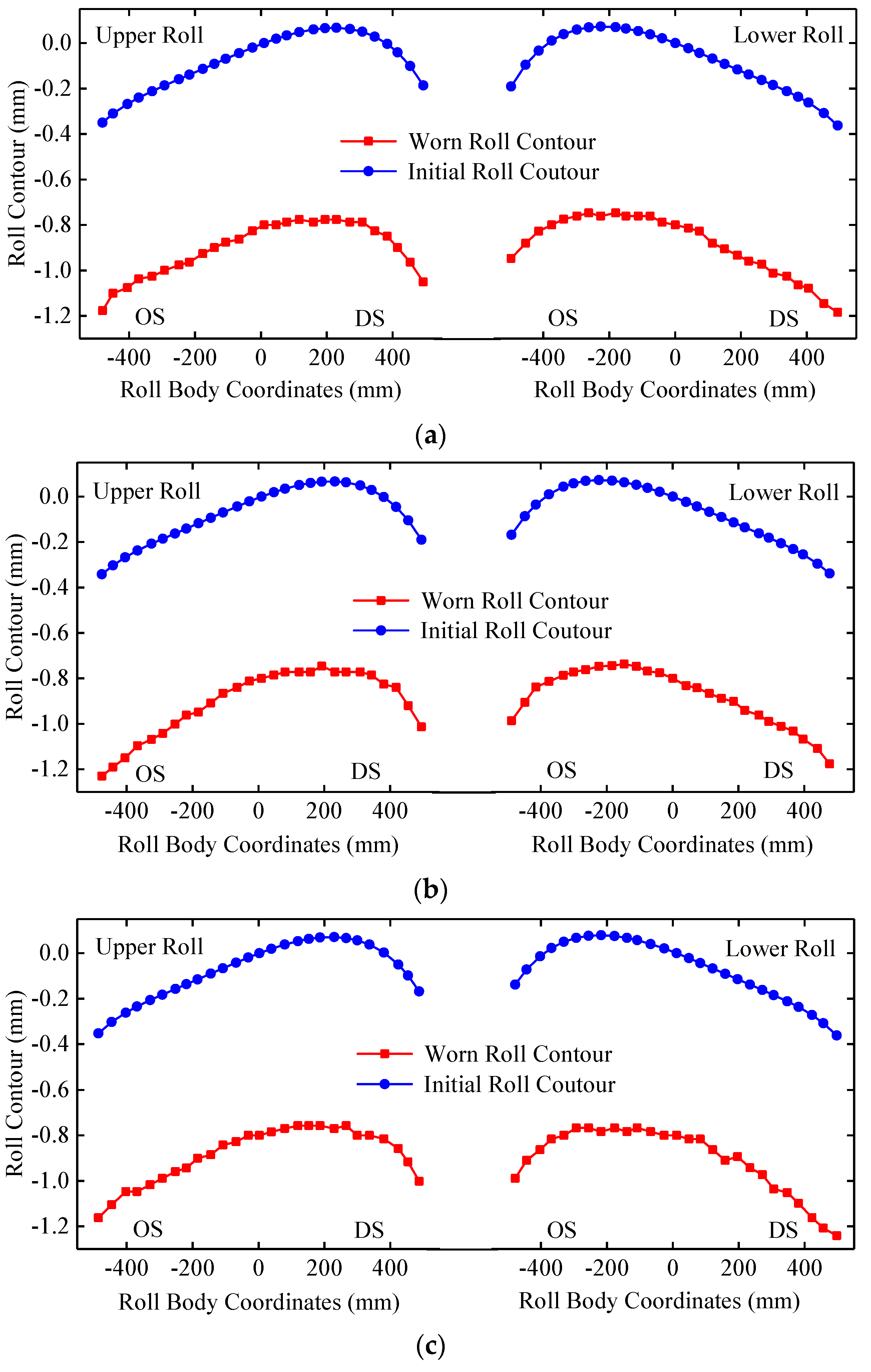
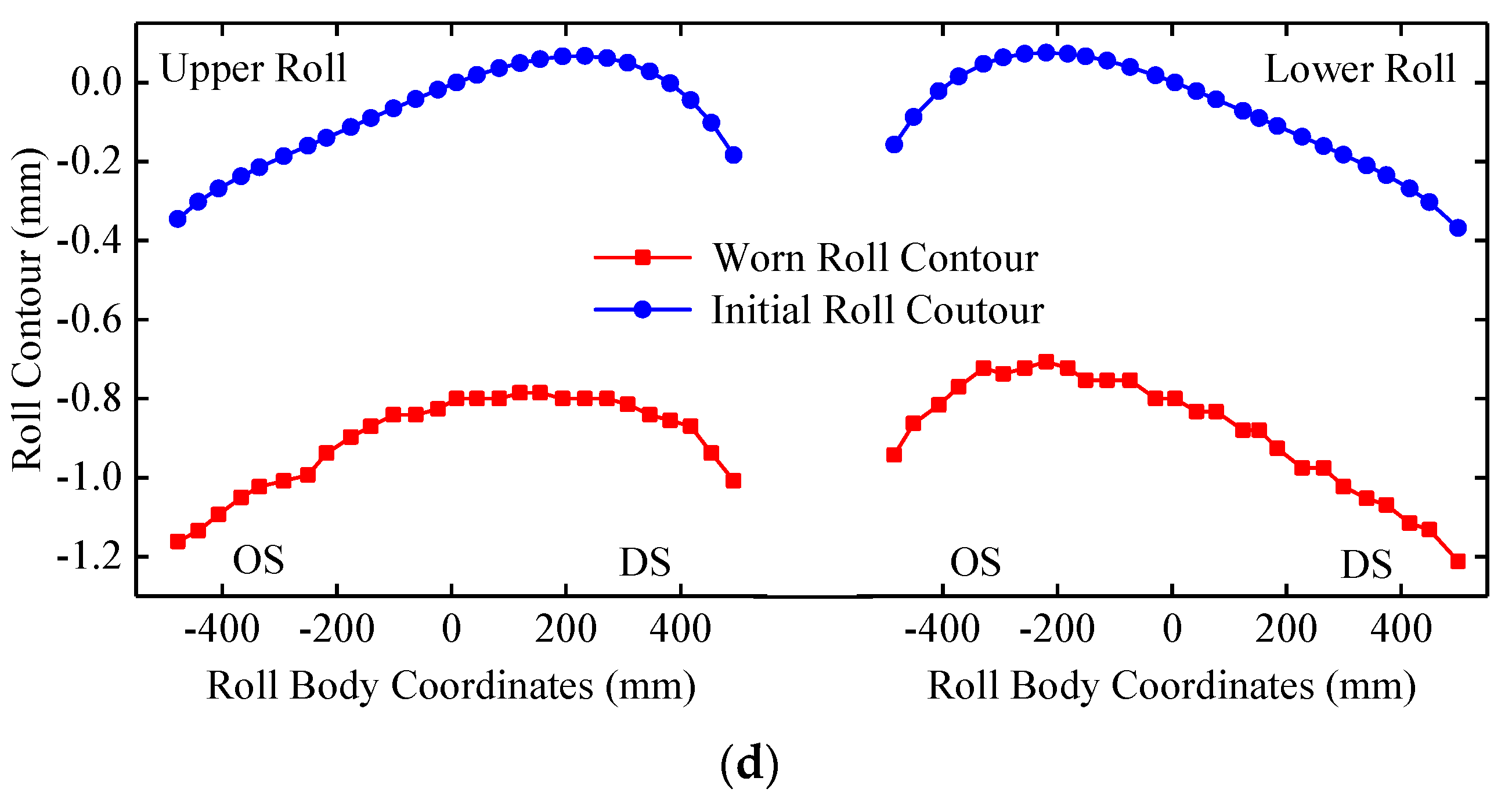
The new roll contour test was carried out on a 1500 mm CVC mill. Figure 15 shows the worn roll contour for a 930 mm length, measured by the VCRplus back-up roll grinder during the test cycle. Through the comparison with Figure 2, it can be seen that after using the VCRplus back-up roll contour, the worn roll contour becomes uniform, which is close to the initial roll contour, indicating that the VCRplus back-up roll contour has a good self-maintenance and stable strip profile control ability during the service period.
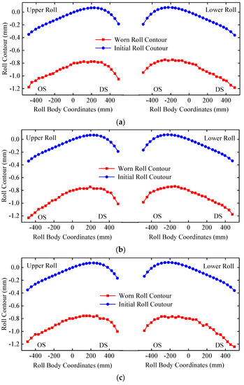
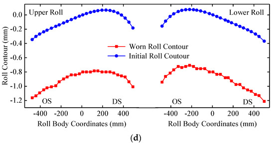
Figure 15.
Worn roll contour of the back-up roll: (a) F1 stand; (b) F1 stand; (c) F2 stand; (d) F2 stand.
VCRplus back-up roll contours have successfully achieved long-term and stable industrial application. During the VCRplus back-up roll contour service period, the rolling capacity extended from 150,000,000 kg to 250,000,000 kg, and spalling accidents did not occur. In addition, during the service period of VCRplus roll contour, the strip profile index is counted, as shown in Table 9. It can be seen that the two strip profile indexes of crown hit rate and flatness hit rate are higher than before, which proves that the VCRplus back-up roll contour has a better strip profile control ability while prolonging the service period.
Table 9.
Index of the strip profile.
Through theoretical analysis and industrial application, it has been proven that VCRplus roll contour technology is economical, easy to implement, and efficient.
8. Conclusions
- (1)
- Finite element simulation was used to analyze the contact pressure between the rolls at the original roll contour of the backup roll. It was found that the uneven distribution of the contact pressure between the rolls and the pressure peaks at both ends of the roll body were key factors for the uneven wear and spalling during the service period.
- (2)
- Through the basic VCR roll contour, considering the uniformity of the contact pressure between the rolls, the VCRplus back-up roll contour has been designed. Through finite element simulation, the VCRplus roll contour can not only uniformize the contact pressure between the rolls, but also improve the bending force control effect and the roll gap transverse stiffness.
- (3)
- Test of the VCRplus back-up roll contour was carried out on site, and the stable industrial application has been realized. The spalling problem of the back-up roll is solved, and the service period of the back-up roll is extended. The rolling capacity has been extended from 150,000,000 kg to 250,000,000 kg with a stable strip profile quality.
Author Contributions
Y.W. led the research, wrote the article, and performed the FEM analysis; H.L. supervised and edited the paper; B.W., N.K., Z.L., and B.L. participated in the discussion of the research. All authors have read and agreed to the published version of the manuscript.
Funding
This research was funded by [the National Key Technology R&D Program of the 12th Five-year Plan of China] grant number [2015BAF30B0].
Acknowledgments
This work is supported by ‘the National Key Technology R&D Program of the 12th Five-year Plan of China’ (grant no. 2015BAF30B0).
Conflicts of Interest
The authors declare no conflict of interest.
References
- Li, H.; Zhang, J.; Cao, J.; He, J.; Zhang, S.; Wang, Q. Characteristics of Backup Roll Wear Contour in a CVC Continuous Hot Rolling Mill. J. Univ. Sci. Technol. Beijing 2008, 5, 558–561. [Google Scholar] [CrossRef]
- Cao, J.-G.; Liu, S.-J.; Zhang, J.; Song, P.; Yan, T.-L.; Zhou, Y.-Z. ASR Work Roll Shifting Strategy for Schedule-free Rolling in Hot Wide Strip Mills. J. Mater. Process. Technol. 2011, 211, 1768–1775. [Google Scholar] [CrossRef]
- Liu, G.M.; Li, Y.G.; Huang, Q.X.; Yang, X. Axial Force Analysis and Roll Contour Configuration of Four-high CVC Mill. Math. Probl. Eng. 2018, 2018, 7527402. [Google Scholar] [CrossRef]
- Ding, J.G.; He, Y.H.; Song, M.X.; Jiao, Z.; Peng, W. Roll Crown Control Capacity of Sextic CVC Work Roll Curves in Plate Rolling Process. Int. J. Adv. Manuf. Technol. 2021, 113, 87–97. [Google Scholar] [CrossRef]
- Cao, J.G.; Wang, Y.P.; Kong, N.; Yang, L.; Hou, A.; Wang, Z. Finite Element Analysis on Affecting Factors of Spalling of The Backup Roll of A Roughing Mill for Stainless Steel. Eng. Mech. 2011, 28, 194–199. [Google Scholar]
- Shang, F.; Li, S.G.; Li, Y.L. Influence Analysis of Roll Configuration on Contact Pressure and Flatness Control. China Metall. 2022, 32, 124–135. [Google Scholar] [CrossRef]
- Wang, Q.L.; Li, X.; Sun, J.; Liu, Y.-M.; Zhang, X.-C.; Wang, Z.-Q. Mathematical and Numerical Analysis of Cross-directional Control for SmartCrown Rolls in Strip Mill. J. Manuf. Process. 2021, 69, 451–472. [Google Scholar] [CrossRef]
- He, A.R.; Yang, Q.; Chen, X.L.; Zhao, L.; Xu, Y.Q. Application of Varying Contact Rolling Technology on Hot Strip Mills. Iron Steel 2007, 42, 31–34. [Google Scholar] [CrossRef]
- He, A.R.; Cao, J.G.; Wu, Q.H.; Gu, Y.; Wei, G.; Yang, J. Study on Comprehensive Function of Varying Contact-length Backup Roll in Finishing Mill of Hot Rolling. Shanghai Met. 2001, 23, 14–17. [Google Scholar]
- Wang, X.D.; Li, F.; Wang, L.; Zhang, X.L.; Dong, L.J. Development and application of roll contour configuration in temper rolling mill for hot rolled thin gauge steel strip. Ironmak. Steelmak. 2012, 39, 163–170. [Google Scholar] [CrossRef]
- Xu, J.Z.; Kong, X.W.; Wang, G.D.; He, X. Strip Crown Control Ability of Large Crown Backup Roll. J. Northeast. University (Nat. Sci.) 2003, 24, 151–154. [Google Scholar] [CrossRef]
- He, A.R.; Huang, T.; Yang, Q.; Chen, X. Development of Integrated Shap Control Technologies in Hot Strip Mills. J. Univ. Sci. Technol. Beijing 2007, 5, 519–522. [Google Scholar] [CrossRef]
- Li, H.B.; Zhang, J.; Cao, J.G.; Wang, Q. Study on the Backup Roll Contour for CSP Continuous Hot Rolling Mill. Iron Steel 2008, 43, 61–64. [Google Scholar] [CrossRef]
- Hao, G.G.; Shao, J.; He, A.R.; Zhang, H.H. Research on Backup Roll Contour for Final Stand of CSP. J. Iron Steel Res. 2010, 22, 15–18+33. [Google Scholar] [CrossRef]
- Shao, J.; He, A.R.; Sun, W.; Yang, Q.; Guan, C.; Wang, Z. Research and Application of VCRplus Technology in Hot Strip Mills. In Proceedings of the 2011 Second International Conference on Mechanic Automation and Control Engineering, Hohhot, China, 18 August 2011; pp. 5120–5123. [Google Scholar]
- Liu, D.Y.; Shao, J.; He, A.R.; Liu, P.Y.; Li, W.J. Influence of Chamfering on Roll Shape Performance of Variable Contact-length Support Roll. Iron Steel 2020, 55, 56–60. [Google Scholar] [CrossRef]
- Li, H.; Zhou, Y.C.; Shen, H.L.; Ning, G.Y. Usage Technology of Back-up Roll in Hanbao 2250 mm Hot Rolling Mill. Steel Roll. 2018, 35, 48–54. [Google Scholar] [CrossRef]
- Zhang, Q.D.; Sun, X.M.; Bai, J. Analysis of Rolls’ Elastic Deformation on CVC 6-h Mill by FEM. China Mech. Eng. 2007, 18, 789–792. [Google Scholar]
- Sheu, J.J.; Ho, C.J.; Yu, C.H.; Kao, C.Y. High-order Groove-shape Curve Roll Design for Aluminum Alloy 7075 Wire Rolling. Metals 2022, 12, 1071. [Google Scholar] [CrossRef]
- Jin, Q.C.; Wang, W.H.; Jiang, R.S.; Chiu, L.N.S.; Liu, D.; Yan, W. A Numerical Study on Contact Condition and Wear of Roller in Cold Rolling. Metals 2017, 7, 376. [Google Scholar] [CrossRef]
- Chen, J.; Zhong, J.; Zhou, H.Z.; Tan, D.G. Analytical model of loaded roll gap for CVC four-high mill. Heavy Mach. 1998, 6, 42–44. [Google Scholar]


Disclaimer/Publisher’s Note: The statements, opinions and data contained in all publications are solely those of the individual author(s) and contributor(s) and not of MDPI and/or the editor(s). MDPI and/or the editor(s) disclaim responsibility for any injury to people or property resulting from any ideas, methods, instructions or products referred to in the content. |
© 2023 by the authors. Licensee MDPI, Basel, Switzerland. This article is an open access article distributed under the terms and conditions of the Creative Commons Attribution (CC BY) license (https://creativecommons.org/licenses/by/4.0/).