Abstract
A proper burden and porosity distribution of the bed in the upper shaft are important prerequisites for realizing a stable and efficient operation of the ironmaking blast furnace. The discrete element method was used to investigate the effects of the static friction coefficient between burden particles and shaft angle on the burden profile and porosity distribution in the bed formed by charging the burden with a bell-less charging equipment. The results indicate that a large static friction coefficient makes the particles stay closer to the impact point (i.e., where they fall) from the rotating chute. A large mixed region of the burden bed decreases the gas permeability, and an increase in the burden particle roughness will worsen this problem. The burden surface shape becomes flatter with an increase in the shaft angle. These findings explain the effect of particle properties and wall geometry on the inner structure of the burden bed.
1. Introduction
The blast furnace (BF) is still the main industrial process for the production of iron for steelmaking. It is a countercurrent three-phase (gas–solid-liquid) system with complex heat, mass, and momentum transfer as well as chemical reactions showing considerable spatial variation. The process accounts for more than 90% of the global hot metal production [1], and this ironmaking–steelmaking route contributes 6–8% of the global anthropogenic greenhouse gas emissions. As a reduction of CO2 emissions from industrial processes is an urgent topic today, some new solutions have been proposed for the blast furnace, for example, highly oxygen-enriched [2] or hydrogen-rich operation of the furnace [3,4] and use of biomass as a reductant [5]. Additionally, the operation stability and efficiency have a large influence on gas utilization and the rate of reductants and emissions, which are all important and mutually interdependent factors.
To achieve a stable and smooth operation of the BF, which is a prerequisite of low reduction and emission rates, four main control schemes are often applied: burden distribution control, thermal control, slag forming control, and blast control [6]. The burden distribution control scheme, also termed top adjustment, manipulates the initial radial distribution of burden materials in the BF. It is today usually realized by the use of a bell-less charging system [7].
There is a strong connection between the overall furnace behavior and the burden bed properties. The reason for this is that the burden distribution determines the porosity distribution of the charged materials and, therefore, also the bed permeability, which, in turn, affects the gas flow distribution. Further, the burden distribution affects the level and shape of the cohesive zone, where the iron-bearing materials start to soften and finally melt. The distribution not only determines the distribution and utilization of gas flow in the BF, but also is an important factor affecting the mass flow rates and the chemical reactions between gas and burden layers, which ultimately significantly affects BF efficiency, operation costs, and the environmental impact.
Particle-scale analysis plays a critical role in gaining a deeper understanding of the mechanisms governing the formation of the burden layers and bed structure in the BF throat and shaft. The burden bed at the top of the BF consists of alternating ore and coke layers, and this layered structure tends to persist during the descent in the throat and shaft. Some researchers used the burden surface profile [8,9,10], ore-to-coke ratio [11,12], or porosity distribution [13,14,15] to characterize the burden distribution at the top of the BF. The burden distribution can be indirectly estimated by observing the bed surface by radar [16,17,18,19] or mechanical profile meters [20,21], but the internal structure can only be accessed by extremely time-consuming sampling after filling of the BF before a blow-in; there are no reliable methods by which the internal bed structure can be measured in an operating blast furnace. To save the effort and time of experimental measurements, a large number of mathematical models of the burden distribution have been proposed. These include data-driven methods [22,23] and first principle models [24,25]. Along with the development of software and computing power, numerical simulation methods have become a choice for more researchers. In particular, the discrete element method (DEM) [26] makes it possible to study complex particulate flow problems. The method has already been widely used to study local or global particulate and multiphase flows in the BF under different conditions. The process and development of simulation methods of the ironmaking BF have been summarized in recent reviews [27,28,29].
Based on the above, it is clear that knowledge about how the burden is distributed at charging and during burden descent is central and useful for designing operation and control strategies and for troubleshooting in the daily operation. DEM has been widely applied in this field [6,8,30,31]. Many researchers investigated the ore-to-coke ratio, which is usually defined as the ratio of the mass of the ore layer and the coke layer along the radial direction of the furnace throat. Fukushima et al. [32] found that a somewhat lower central ore-to-coke ratio should be maintained to keep good gas permeability and a stable state of the melting zone. Zhou et al. [12] investigated the effects of reverse charging, coke platform width, central coke charging, and pellet ratio on the ore-to-coke ratio using a three-dimensional model. In order to optimize the BF operation, some researchers have paid attention to other factors that affect the burden distribution. Ho et al. [31] demonstrated that the burden distribution is influenced by particle density, size, chute angle, and distance between the bin and chute. Kou et al. [30] investigated the corresponding effects of distributor angle, rotating speed and length, and the stock line on burden profiles and distribution along the radius in the upper part of a COREX shaft furnace.
The studies discussed above have improved our understanding of the BF process related to the burden distribution. However, most of the studies were focused on a macroscopic view. The permeability or porosity of the burden bed in the BF throat, which is closely related to the burden distribution along the radial and vertical direction of the throat, is also an important aspect reflecting the inner structure, which affects the distribution of the gas flow. In BF models, the Ergun equation [33] has usually been applied to predict the global pressure drop in the furnace using a constant porosity in the layers. From this equation, it can be seen that even a small decrease in porosity along the vertical or radial direction of the bed would significantly influence the permeability of the whole bed and, therefore, the gas flow resistance and distribution. Even though many factors that affect the burden distribution also influence the porosity distribution, there are not many papers in the literature that have studied the latter aspect. The burden surface profile in the throat is related to the charging matrix, as well as the particle size, density, and surface roughness of the burden particles. The friction coefficient is a parameter that reflects the roughness of a particle. Some other investigations [34,35,36] and earlier works of the present authors [37,38] have demonstrated that the friction coefficient has a quite large effect on the porosity distribution of a particle pile. In addition, the charged burden redistributes as it descends from the stockline. The operation condition of the BF is strongly influenced by the burden redistribution due to the local ore reduction and coke gasification [39]. Studies [40,41] have been conducted on the descending behavior of burden, demonstrating that the descent rate and the height of the stockline affect the burden and porosity distribution in the blast furnace shaft.
The main objective of the research described in this paper is to gain a better understanding of the inner structure of the burden materials after charging and the impacts of some factors on the radial and vertical porosity distribution in the BF throat and upper shaft. This paper is organized as follows: In Section 2, DEM is introduced. The section also presents the problem tackled and the simulation conditions. Section 3 reports the results and discusses the findings of the study of the effects of static friction coefficient and shaft angle on the radial and vertical porosity distribution of the burden bed. Finally, conclusions are drawn in Section 4.
2. Methodology
2.1. Discrete Element Method
DEM is a numerical method for the simulation of the interaction of particles, which was first proposed by Cundall and Strack [26]. The method is based on Newton’s second law of motion combined with a force–displacement correlation at the points of contact between particles or between particles and surfaces. The interaction forces of two particles in contact are shown in Figure 1. The method considers two states of motion of particles, translational and rotational, and applies a model of the contact of the particles. In this work, the open-source software LIGGGHTS was used with the nonlinear Hertz–Mindlin no-slip contact model. The governing equations for the motion of particle i with mass mi and the moment of inertia Ii in contact with N other particles j can be written as:
where and are the translational and angular velocities of the particle, respectively, and and are the torques of tangential force and rolling friction force. is the gravity acceleration. For the alternative elastic-plastic spring-dashpot (EPSD2) model, which was used in this study, the viscous damping torque was disabled. The terms and express the normal and tangential overlap distances of two particles, and represent the normal and tangential components of the relative speed of the two particles, and are the normal and tangential elastic constants, and and are the normal and tangential viscoelastic damping constants. These can be calculated by [42,43]:
where Y, e, and ν represent the properties of the particle, namely, Young’s modulus, coefficient of restitution, and Poisson’s ratio, respectively, and and are the particle radii.

Figure 1.
Interaction forces between two particles (i and j) in DEM.
The torque due to the spring is calculated as:
where is the tangential stiffness and is the rolling stiffness, is the effective radius, and is the relative rotation increment between the particles. The spring torque is limited by the full mobilization torque, , which is determined by the normal force, , and the coefficient of rolling friction, The friction force is expressed with a Coulomb-type friction law. It defines that the tangential force Ft of a particle should be no more than the normal force, Fn, multiplied by the static friction coefficient,
2.2. System Studied
The model applied in the analysis of the present work is the same as the one developed in a previous work by the authors [14], which demonstrated the model validity through a comparison between simulated radial porosity distribution of coke layers and experimentally observed porosities. The charging system modeled is a downscaled (1:10) variant of that of an industrial blast furnace (Nangang Steel Company, Nanjing China), as shown in Figure 2, with a slot model of the throat and a full model of the shaft. The former is used to study the effects of physical parameters and a moving stockline on the porosity distribution of the burden bed in the BF throat. This simplified setup helps save computational time. It is established based on the assumptions that the BF throat is axisymmetric and is charged symmetrically, and the wall effect from the front and back slot planes is negligible. The latter setup is used to investigate how the porosity distribution of the burden bed changes when the shaft diameter grows, and is three-dimensional to appropriately consider the volume change along with the increase in the shaft diameter. It is worth noting that the charging system is the same in both studies.
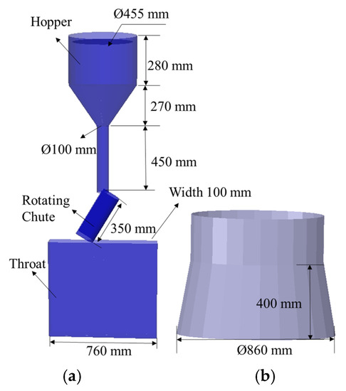
Figure 2.
Models of the charging system with slot throat (a) and whole shaft (b) used in the simulation.
The simulation process can be shortly described as follows: Particles are randomly generated to gather in the hopper and are then regularly released to be distributed in the throat by the rotating chute applying a given charging matrix, with the chute angles 37°, 34°, and 31° for the throat model simulation and 37° and 31° for the shaft simulation, where the reported values express the angle between the chute and the rotational axis. One ring of particles is charged for each angle. The rotation speed of the chute is 8 r/min, and the original stockline (i.e., the distance between the burden surface and the lower edge of the chute) is 0.24 m. For the slot model, when the chute rotates outside of the slot throat, particles will be deleted. The throat model holds six burden layers, while the shaft model has three layers to reduce the computation effort. It was found that three layers were sufficient to fill the shaft part considered. To calculate the porosity distribution of the burden layers, the particle bed is divided into several virtual boxes (14 boxes for the throat model and 8 for the shaft model), counting the number of particles in each box on the basis of the position of the particles’ centers. The size of the virtual box is 50 mm × 100 mm × 40 mm, which is large enough to ignore the effects of the walls on the porosity. The porosity is obtained as , where ni expresses the number of particles in a virtual box, and is the volume of a particle of type i, while Vbox is the volume of the virtual box. Earlier research has shown that spherical particles with adjusted coefficients of rolling friction can accurately consider the effect of particle shape on the behavior of the granular system in BFs [44,45]. The particle size and the mass ratio of particles of different sizes studied in this work are reported in Table 1. Since a particle size reduction to 1/10 of the actual one would yield too small particles, a particle size representing 1/4 of the actual size was used, supported by findings from earlier research [14]. In the shaft model, the mass fraction of small particles was increased to make sure that more small particles can participate in the permeation for the simplified charging matrix studied. Table 1 also reports the number of particles for the slot and three-dimensional models. As for DEM parameters, Table 2 presents the settings, which are largely based on what has been reported in the literature [46,47] and earlier measurements by the present authors [48].

Table 1.
Properties of sinter and coke in the simulation. The particle size is 1/4 of the actual particle size.
Table 2.
Parameters used in DEM simulation.
This work investigates the effects of the static friction coefficient between the particles on the porosity distribution along the radial and vertical direction of the burden bed, considering the different types of particles in contact. In the blast furnace, the burden bed is continuously descending after charging. If the charging cannot be sped up when the burden descends fast, the level of the stockline will decrease. In this research, a moving stockline can be achieved by changing the fixed descent rate of the burden bed at the lower end of the domains, which was set to 0.0025, 0.05, and 0.1 m/s, assuming that the rate is radially uniform. The porosity distribution of the burden bed in the shaft is also studied for different shaft angles (80°, 83°, and 85°) of the shaft model. Figure 3 shows examples of simulated results of the throat (slot) model and the shaft model, where sinter is depicted by blue and coke by red. It is worth noting that the two bottom layers in Figure 3a act as the base to establish an inclined burden profile for the charged burden layers. The base layers are the same for all cases to ensure identical initial conditions. It can be seen that the burden shape is of platform + funnel type (cf. Figure 3a), which corresponds to a common pattern encountered in industrial blast furnaces, and that the static friction coefficient plays an important role.
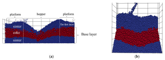
Figure 3.
Examples of cross section of simulation results for throat model (a) and shaft model (b).
3. Results and Discussion
3.1. Static Friction Coefficient between Particles
The static friction coefficient of particles includes the coefficient between the same types of particles and between particles of different types. In the BF, the ore (sinter or pellet) and coke are alternately charged layer by layer, so the effects of the static friction coefficient of sinter–coke, sinter–sinter, and coke–coke were studied in this work, as outlined in Table 3. Figure 4 shows a vertical cross section of the burden for different static friction coefficients. With the increase in the static friction coefficient between sinter and coke, sinter and sinter, coke and coke, more particles stay at the platform rather than moving down the funnel to the center, while for small friction coefficients, more particles gather in the funnel. From the enlarged figures in Figure 4, it can be seen that for a mixed region where the sinter is above the coke, the smaller sinter particles penetrate into the voids between the larger coke particles and then gather at the intermediate position if the static friction coefficient is small (cf. region enclosed by the white dotted ellipse). In addition, for the coke, a higher surface roughness (large static friction coefficient) makes it easier for the particles to accumulate near the furnace wall. In the BF, this leads to a “wall-working” gas distribution, which increases heat losses and wall wear, possibly affecting the campaign life length of the BF.
Table 3.
Simulation cases with different static friction coefficients.
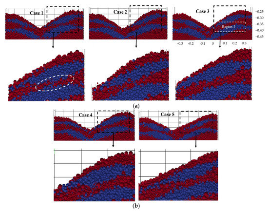
Figure 4.
Simulation results of the cross sections of burden layers and local enlarged figures showing the effect of a growing static friction coefficient of sinter−coke (a) and sinter–sinter and coke–coke (b).
Region 1 in Figure 4 with a size of 0.3 m × 0.1 m × 0.1 m was chosen to further clarify the effects of the static friction coefficient on the radial porosity distribution of the burden layers. Since the blast furnace is charged symmetrically, only 1/2 of the burden bed is considered here. This region was selected to include enough of the bed, but not the wall region where the local porosity is affected by the boundary. Figure 5 shows the radial porosity distribution in Region 1 for different static friction coefficients between particles of different types and between the same types of particles. From Figure 5a,b, it is seen that the porosity increases with the increase in the static friction coefficient for X > 0.1 m, which corresponds to a distance of about 1/3 of the radius from the center. However, for X < 0.1 m, the result is opposite. It is worth noting that the porosity changes little when the static friction coefficient increases further (cf. Cases 2 and 3 in Figure 5a). In addition, there is an increasing porosity trend around the center area for Figure 5b compared with Figure 5a because the large coefficient of static friction between the same types of particles and between particles of different types leads to fewer particles gathering here.

Figure 5.
Radial porosity distribution in Region 1 of Figure 4 for different static friction coefficients of sinter–coke (a) and sinter–sinter and coke–coke (b).
The static friction coefficient influences the ability of particles to move on the burden slope and the permeability of small particles into the voids of large particles. For particles in the intermediate and wall region, the permeability of particles (small sinters) into the voids of large ones has major effects on the porosity. In this region, increasing the static friction coefficient makes it more difficult for small particles to penetrate into the voids of large particles, which results in a large bed porosity. This can be further studied in Figure 6, which shows the mass fraction distribution of the smallest (3 mm) sinter in the mixed region of sinter and coke (i.e., upper half of Region 1). The green dotted lines represent the original mass friction of the smallest sinter in the burden bed. The mass fraction of small sinter decreases with the increase in the static friction coefficient at the intermediate position of the throat, which is the main mixed region. This phenomenon can be seen in Figure 7, where the occurrence of the smallest sinter size (dark blue) shows a decreasing trend from the top to the bottom panel. For particles close to the center position, the particle movability along the burden slope influences the porosity. A large static friction coefficient makes it more difficult for small particles to move to the center position, while some larger ones gather there, resulting in a large bed porosity. However, when the coefficients of static friction between the same types of particles and between particles of different types are all large (Cases 4 and 5), it is difficult for both the large and small particles to move. Therefore, for a BF burden of the platform + hopper profile, which has a slope, increasing the static friction coefficient of sinter–sinter, coke–coke, or sinter-coke will increase the porosity close to the “platform” region (the wall position of the throat) and decrease the porosity close to the “hopper” region.
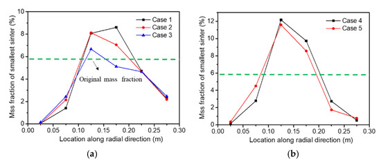
Figure 6.
Mass fraction distribution of the smallest sinter (3 mm) of the burden bed in the upper part (0.3 m × 0.1 m × 0.04 m) of Region 1, where the sinter layer is above the coke layer for growing static friction coefficients of sinter–coke (a) and sinter–sinter and coke–coke (b).
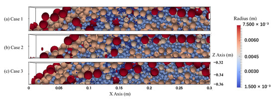
Figure 7.
Local cross section of the particles in the mixed region with a sinter layer above the coke layer for growing static friction coefficients of sinter–coke from top to bottom.
Figure 8b shows the vertical porosity distribution in the bed for different static friction coefficients of sinter–coke corresponding to the region depicted in Figure 8a. The burden bed was divided into five subareas along the vertical direction, and the reported porosities are averages for each subarea, excluding empty areas. The layered structure and the mixing effect caused by particles in different layers lead to a zigzag porosity pattern in the BF throat, which is in agreement with the findings of earlier works by the authors [14] and results presented in the literature [49]. For burden bed areas (1 and 2) without inclined parts, the change of porosity is not obvious. Overall, from the bottom to the top of the burden bed, the porosity increases as a result of the compacting caused by the weight of the overlaying burden and percolation of small particles into the void between large particles [50]. However, the porosity shows a sudden increase in the region (Area 3) where the coke layer is above the sinter layer due to lack of a mixed layer. The porosity in Area 4 decreases because of the occurrence of mixed regions where a layer of sinter of small size lies above the coke layer. As mentioned above, the porosity will decrease in the mixed layer because of the permeation of small sinter. For the mixed region (Area 4), the porosity increases with the static friction coefficient since the higher friction makes the percolation less likely. It should be stressed that the size difference between sinter and coke particles is the main reason for the formation of mixed layers.
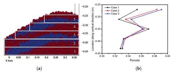
Figure 8.
(a) Division of the bed in the throat into subareas and (b) corresponding vertical porosity distribution for different static friction coefficients of sinter–coke.
3.2. Shaft Angle
When the burden that has been charged into the BF throat descends into the furnace shaft, it will also move radially due to the increase of diameter. In this process, the shaft angle is an important factor influencing the burden distribution. Figure 9 shows the size of models of the BF top with different shaft angles (α = 80°, 83°, and 85°), which were used to study the effects of shaft angle on the burden and porosity distributions of the bed. Since the furnace height was kept constant, an increasing shaft angle means that the diameter of the throat also increases, as indicated in the figure.
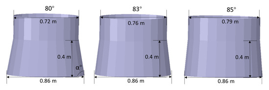
Figure 9.
Models of different shaft angles (α) in the simulation.
Some simulation results are depicted in Figure 10, indicating that the burden surface becomes more horizontal with the increase in the shaft angle, especially for the coke layers. The angles () between the coke layer and the horizontal plane are 17.8°, 16.2°, and 15.7° for the shaft angles 80°, 83°, and 85°, respectively. A large shaft angle makes particles move outwards, and thus, the “funnel” of the burden surface is not so marked. This will lead to a more uniform burden distribution from the wall to the center of the BF. Figure 11 shows the radial porosity distribution of the burden bed in Region 2 (mixed layer) indicated in Figure 10 at the boundary between the throat and the shaft, where the angle of the wall changes. The porosity of the individual sinter and coke layers is about 0.41 and 0.36, respectively, so the porosity in the mixed region is clearly lower. For all the shaft angles, the porosity decreases from the wall to the center, but the porosity shows large differences at the wall because of the wall effect. Generally, the porosity close to the wall decreases with the increase in the shaft angle, but the effect is minor farther from the wall. The bars in the insert of Figure 11 show the average porosity of Region 2, with standard deviations indicated in red. When the shaft angle increases, the standard deviation decreases, which demonstrates that a large shaft angle decreases the nonuniformity of the porosity distribution from the edge to the center of the shaft.
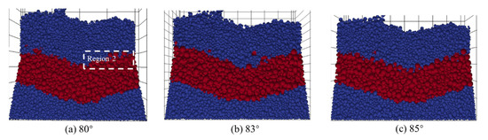
Figure 10.
Cross section of burden profiles for different shaft angles.

Figure 11.
Radial porosity distribution in the mixed region (Region 2 in Figure 10) where the sinter layer is above the coke layer for different shaft angles. The inserted graph is the average porosity in the mixed region.
The shaft angle has greatest effects on the porosity near the BF wall, so it was studied in more detail. The vertical porosity distribution of burden layers close to the wall is depicted in Figure 12, determined by taking averages of the porosity in the areas indicated by the dashed white boxes in the left subpanel. The porosity is seen to decrease from the top to the bottom of the burden bed. The shaft angle affects the vertical porosity distribution, especially for the turning point from the throat to the shaft (three middle boxes in the left figure of Figure 12). These results are consistent with the experimental findings reported by Ichida et al. [50], which demonstrated that the burden particles near the furnace wall are rearranged in a relatively short time at the extension of the shaft section as a so-called wall effect. However, as also seen in the figure, the porosity becomes larger at the wall when the shaft angle decreases. In addition, there is no zigzag increase when the shaft angle is small (e.g., 80°). This is caused by the larger void free at the wall, which the particles cannot densely fill, and the effect of the mixed layer is therefore unimportant. In the blast furnace, such porosity increase will cause an increased local gas flow rate, which may be detrimental for the furnace operation in terms of increased heat loss and wear of the refractory, but may be beneficial if large quantities of (smaller) ore are charged at the wall. For the layer parts far away from the considered region (not shown here), the influence of the shaft angle is small.
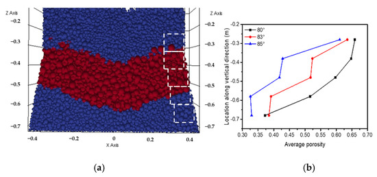
Figure 12.
Cross section of burden profile (a) and vertical porosity distribution of burden layers close to the wall of the upper shaft and throat (b).
4. Conclusions
Some factors affecting the burden surface profile and porosity distribution of the burden bed in the upper part of the blast furnace charged with sinter and coke have been studied numerically. Two 1/10 scale simulation models of the upper part of the furnace were developed: a two-dimensional slot throat model and a three-dimensional shaft model, both with the same charging system. The discrete element method (DEM) was applied to study the arising particle bed and its properties. For the applied charging matrix, where two or three rings of ore and coke were charged with the same set of chute angles, the arising burden surface shape can be characterized as “platform + funnel”. The results of the study can be condensed in the following main findings:
- (1)
- The static friction coefficient between particles affects the radial porosity distribution of the burden layers in the throat. With an increase in the coefficient, more particles stay at the platform or upper slope rather than moving to the funnel part, especially for small particles.
- (2)
- An increased burden particle roughness will make the porosity drop in the mixed layers less pronounced. This will improve the gas permeability of the blast furnace.
- (3)
- The burden surface shape becomes flatter with an increase in the shaft angle. The shaft angle of the BF also affects the burden distribution and porosity of the burden bed at the position of the turning point from the BF throat to the shaft for the region close to the wall.
- (4)
- A properly chosen shaft angle can make the burden distribution more uniform and reduce the change of the porosity distribution during burden descent, but the angle has naturally other effects of the BF performance that also should be considered.
The findings of the present work are somewhat constrained by the limited number of cases studied. In future work, different charging programs should be studied to make more definite conclusions about the effects of factors on the porosity distribution. The simulations should rather be based on a sector model than a slot or full model of the throat and shaft, as this would more realistically reflect the true process without prohibitive numerical efforts. Obviously, an experimental verification of the findings would also strengthen the conclusions.
Author Contributions
Methodology, H.W. and H.S.; software, H.W.; validation, H.W.; writing—original draft preparation, H.W.; writing—review and editing, H.S.; supervision, H.S. and Y.Y.; funding acquisition, Y.Y. All authors have read and agreed to the published version of the manuscript.
Funding
This research was funded by NSFC grant number 51974182. The APC was funded by Henrik Saxén, Åbo Akademi University.
Institutional Review Board Statement
Not applicable.
Data Availability Statement
Not applicable.
Acknowledgments
The discrete element method simulations and analysis were conducted using LIGGGHTS 3.5.0 open source.
Conflicts of Interest
The authors declare that they have no conflict of interest.
References
- Kurunov, I.F. The blast-furnace process—Is there any alternative? Metallurgist 2012, 56, 241–246. [Google Scholar] [CrossRef]
- Nie, H.; Li, Z.; Kuang, S.; Yan, L.; Zhong, W.; Yu, A.; Mao, X.; Xu, H. Numerical investigation of oxygen-enriched operations in blast furnace ironmaking. Fuel 2021, 296, 120662. [Google Scholar] [CrossRef]
- Lan, C.; Hao, Y.; Shao, J.; Zhang, S.; Liu, R.; Lyu, Q. Effect of H2 on blast furnace ironmaking: A review. Metals 2022, 12, 1864. [Google Scholar] [CrossRef]
- Qie, Y.N.; Lyu, Q.; Lan, C.C.; Zhang, S.H.; Liu, R. Effect of H2 addition on process of primary slag formation in cohesive zone. J. Iron Steel Res. Int. 2019, 27, 132–140. [Google Scholar] [CrossRef]
- Seo, M.W.; Jeong, H.M.; Lee, W.J.; Sang, J.Y.; Sang, M.J. Carbonization characteristics of biomass/coking coal blends for the application of bio-coke. Chem. Eng. J. 2020, 394, 124943. [Google Scholar] [CrossRef]
- Yang, Y.L.; Yin, Y.; Wunsch, D.; Zhang, S.; Chen, X.D.; Li, X.; Cheng, S.S.; Wu, M.; Liu, K.Z. Development of blast furnace burden distribution process modeling and control. ISIJ Int. 2017, 57, 1350–1363. [Google Scholar] [CrossRef]
- Geerdes, M.; Chaigneau, R.; Lingiardi, O.; Molenaar, R.; Opbergen, R.; Sha, Y.; Warren, P. Modern Blast Furnace Ironmaking: An Introduction, 4th ed.; IOS Press: Amsterdam, The Netherlands, 2020. [Google Scholar]
- Fu, D.; Chen, Y.; Zhou, C.Q. Mathematical modeling of blast furnace burden distribution with non-uniform descending speed. Appl. Math. Model. 2015, 39, 7554–7567. [Google Scholar] [CrossRef]
- Hinnelä, J.; Saxén, H.; Pettersson, F. Modeling of the blast furnace burden distribution by evolving neural networks. Ind. Eng. Chem. Res. 2003, 42, 2314–2323. [Google Scholar] [CrossRef]
- Liu, S.D.; Zhou, Z.Y.; Dong, K.J.; Yu, A.B.; Pinson, D.; Tsalapatis, J. Numerical investigation of burden distribution in a blast furnace. Steel Res. Int. 2015, 86, 651–661. [Google Scholar] [CrossRef]
- Król, L.; Krzaklewski, M.; Olek, T.; Woźniacki, W. Identification of burden distribution parameters in shaft and throat of the blast furnace. Steel Res. 1988, 59, 146–152. [Google Scholar] [CrossRef]
- Zhou, H.; Wu, J.L.; Hong, Z.B.; Wang, L.P.; Wu, S.L.; Kou, M.Y.; Wang, G.W.; Luo, Y.W. Numerical simulation of coke collapse and its optimization during burden charging at the top of bell-less blast furnace. Powder Technol. 2021, 389, 155–162. [Google Scholar] [CrossRef]
- Rankin, W.; Roller, P. The measurement of void fraction in beds of granulated iron ore sinter feed. Trans. Iron Steel Inst. Jpn. 1985, 25, 1016–1020. [Google Scholar] [CrossRef]
- Wei, H.; Ding, W.T.; Li, Y.; Nie, H.; Saxén, H.; Long, H.M.; Yu, Y.W. Porosity distribution of moving burden layers in the blast furnace throat. Granul. Matter 2021, 23, 10. [Google Scholar] [CrossRef]
- Li, C.Z.; Honeyands, T.; O’Dea, D.; Moreno-Atanasio, R. DEM study on size segregation and voidage distribution in green bed formed on iron ore sinter strand. Powder Technol. 2019, 356, 778–789. [Google Scholar] [CrossRef]
- Kawata, Y.; Kusaka, T.; Inoue, K.; Imada, H.; Miyakawa, H. An FM radar based on a new phase modulation method for burden level measurement in blast furnace. Trans. Soc. Instrum. Control Eng. 1986, 22, 1189–1195. [Google Scholar] [CrossRef]
- Zhu, Q.; Lu, C.L.; Yin, Y.X.; Chen, X.Z. Burden distribution calculation of bell-less top of blast furnace based on multi-radar data. J. Iron Steel Res. Int. 2013, 20, 33–37. [Google Scholar] [CrossRef]
- Kelly, J.R.; Wei, J.D.; Chen, X.Z.; Cui, Y.Z. Blast furnace stockline measurement using radar. Ironmak. Steelmak. Prod. Appl. 2015, 42, 533–541. [Google Scholar]
- Li, M.; Wei, H.; Ge, Y.; Xiao, G.C.; Yu, Y.W. A mathematical model combined with radar data for bell-less charging of a blast furnace. Processes 2020, 8, 239. [Google Scholar] [CrossRef]
- Duan, J.; Zhang, W. Research on the blast furnace charge position tracking based on machine learning regression model. In Proceedings of the 10th International Conference on Modelling, Identification and Control (ICMIC), Guiyang, China, 2–4 July 2018. [Google Scholar]
- Saxén, H.; Nikus, M.; Hinnelä, J. Burden distribution estimation in the blast furnace from stockrod and probe signals. Steel Res. 1998, 69, 406–412. [Google Scholar] [CrossRef]
- Hinnelä, J.; Saxén, H. Neural network model of burden layer formation dynamics in the blast furnace. ISIJ Int. 2001, 41, 142–150. [Google Scholar] [CrossRef]
- Zhou, P.; Shi, P.Y.; Song, Y.P.; Tang, K.L.; Fu, D.; Zhou, C. Evaluation of burden descent model for burden distribution in blast furnace. J. Iron Steel Res. Int. 2016, 23, 765–771. [Google Scholar] [CrossRef]
- Radhakrishnan, V.R.; Ram, K.M. Mathematical model for predictive control of the bell-less top charging system of a blast furnace. J. Process Control 2001, 11, 565–586. [Google Scholar] [CrossRef]
- Nag, S.; Koranne, V. Development of material trajectory simulation model for blast furnace compact bell-less top. Ironmak. Steelmak. 2009, 36, 371–378. [Google Scholar] [CrossRef]
- Cundall, P.; Strack, O. A discrete numerical mode for granular assemblies. Géotechnique 1979, 29, 47–65. [Google Scholar] [CrossRef]
- Dong, X.; Yu, A.B.; Yagi, J.I.; Zulli, P. Modelling of multiphase flow in a blast furnace: Recent developments and future work. ISIJ Int. 2007, 47, 1553–1570. [Google Scholar] [CrossRef]
- Ueda, S.; Natsui, S.; Nogami, H.; Yagi, J.I.; Ariyama, T. Recent progress and future perspective on mathematical modeling of blast furnace. ISIJ Int. 2010, 50, 914–923. [Google Scholar] [CrossRef]
- Kuang, S.; Li, Z.; Yu, A. Review on modelling and simulation of blast furnace. Steel Res. Int. 2018, 89, 1700071. [Google Scholar] [CrossRef]
- Kou, M.; Shengli, W.U.; Kaiping, D.U.; Shen, W.; Sun, J.; Zhang, Z. DEM simulation of burden distribution in the upper part of COREX shaft furnace. ISIJ Int. 2013, 53, 1002–1009. [Google Scholar] [CrossRef]
- Ho, C.K.; Wu, S.M.; Zhu, H.P.; Yu, A.B.; Tsai, S.T. Experimental and numerical investigations of gouge formation related to blast furnace burden distribution. Miner. Eng. 2009, 22, 986–994. [Google Scholar] [CrossRef]
- Fukushima, T.; Nishio, H.; Ohno, Y.; Furukawa, T.; Izawa, T. Importance of Burden Distribution Control and Inner State of the Blast Furnace, Symposium on Optimum Burden Distribution in the Blast Furnace; McMaster University Press: Hamilton, ON, Canada, 1978; pp. 7.1–7.14. [Google Scholar]
- Tsotsas, E.; Schlünder, E.U. Heat transfer in packed beds with fluid flow: Remarks on the meaning and the calculation of a heat transfer coefficient at the wall. Chem. Eng. Sci. 1990, 45, 819–837. [Google Scholar] [CrossRef]
- Zhou, Y.C.; Xu, B.H.; Yu, A.B.; Zulli, P. An experimental and numerical study of the angle of repose of coarse spheres. Powder Technol. 2002, 125, 45–54. [Google Scholar] [CrossRef]
- Rojek, J.; Zarate, F.; Saracibar, C.; Gilbourne, C.; Verdot, P. Discrete element modelling and simulation of sand mould manufacture for the lost foam process. Int. J. Numer. Methods Eng. 2005, 62, 1421–1441. [Google Scholar] [CrossRef]
- Wensrich, C.; Katterfeld, A. Rolling friction as a technique for modelling particle shape in DEM. Powder Technol. 2012, 217, 409–417. [Google Scholar] [CrossRef]
- Wei, H.; Li, M.; Li, Y.; Ge, Y.; Saxen, H.; Yu, Y.W. Discrete element method (DEM) and experimental studies of the angle of repose and porosity distribution of pellet pile. Processes 2019, 7, 561. [Google Scholar] [CrossRef]
- Wei, H.; Zan, L.; Li, Y.; Wang, Z.; Saxén, H.; Yu, Y. Numerical and experimental studies of corn particle properties on the forming of pile. Powder Technol. 2017, 321, 533–543. [Google Scholar] [CrossRef]
- Zhang, S.J.; Yu, A.B.; Zulli, P.; Wright, B.; Austin, P. Numerical simulation of solids flow in a blast furnace. Appl. Math. Model. 2002, 26, 141–154. [Google Scholar] [CrossRef]
- Nishio, H.; Ariyama, T. Analysis on formation processes of burden distribution in blast furnace. Tetsu-to-Hagane 1982, 68, 2330–2337. [Google Scholar] [CrossRef] [PubMed]
- Fu, D.; Huang, F.; Tian, F.; Zhou, C. Burden descending and redistribution in a blast furnace. In Proceedings of the Association for Iron & Steel Technology Conference, Pittsburgh, PA, USA, 3–6 May 2010. [Google Scholar]
- Di Renzo, A.; Di Maio, F.P. An improved integral non-linear model for the contact of particles in distinct element simulations. Chem. Eng. Sci. 2005, 60, 1303–1312. [Google Scholar] [CrossRef]
- Hertz, H. Ueber die Berührung fester elastischer Körper. J. Reine Angew. Math. 1882, 1882, 156–171. [Google Scholar] [CrossRef]
- Soda, R.; Sato, A.; Kano, J.; Kasai, E.; Saito, F.; Hara, M.; Kawaguchi, T. Analysis of granules behavior in continuous drum mixer by DEM. ISIJ Int. 2009, 49, 645–649. [Google Scholar] [CrossRef]
- Nakano, M.; Abe, T.; Kano, J.; Kunitomo, K. DEM analysis on size segregation in feed bed of sintering machine. ISIJ Int. 2012, 52, 1559–1564. [Google Scholar] [CrossRef]
- Yu, Y.; Saxén, H. Segregation behavior of particles in a top hopper of a blast furnace. Powder Technol. 2014, 262, 233–241. [Google Scholar] [CrossRef]
- Barrios, G.K.P.; De Carvalho, R.M.; Kwade, A.; Tavares, L.M. Contact parameter estimation for DEM simulation of iron ore pellet handling. Powder Technol. 2013, 248, 84–93. [Google Scholar] [CrossRef]
- Wei, H.; Nie, H.; Li, Y.; Saxén, H.; He, Z.J.; Yu, Y.W. Measurement and simulation validation of DEM parameters of pellet, sinter and coke particles. Powder Technol. 2020, 364, 593–603. [Google Scholar] [CrossRef]
- Mitra, T.; Saxén, H. Discrete element simulation of charging and mixed layer formation in the ironmaking blast furnace. Comput. Part. Mech. 2016, 3, 541–555. [Google Scholar] [CrossRef]
- Ichida, M.; Anan, K.; Takao, M.; Kakiuchi, K.; Morizane, Y.; Yamada, I.; Nakayama, T. Inner profile and burden descent behavior in the blast furnace. Tianjin Metal. 2006, 384, 80–86. [Google Scholar]
Disclaimer/Publisher’s Note: The statements, opinions and data contained in all publications are solely those of the individual author(s) and contributor(s) and not of MDPI and/or the editor(s). MDPI and/or the editor(s) disclaim responsibility for any injury to people or property resulting from any ideas, methods, instructions or products referred to in the content. |
© 2023 by the authors. Licensee MDPI, Basel, Switzerland. This article is an open access article distributed under the terms and conditions of the Creative Commons Attribution (CC BY) license (https://creativecommons.org/licenses/by/4.0/).