Article

Microstructure of Butt Joint of High-Silicon Steel Made Using CO2 Laser Welding and Inconel 82 Filler

1
Iron and Steel Research & Development Department, China Steel, Kaohsiung 812, Taiwan
2
Department of Materials Science and Engineering, National Taiwan University, Taipei 106, Taiwan
*
Author to whom correspondence should be addressed.
Metals 2023, 13(2), 234; https://doi.org/10.3390/met13020234
Submission received: 18 December 2022 / Revised: 24 January 2023 / Accepted: 24 January 2023 / Published: 26 January 2023
(This article belongs to the Special Issue Laser Welding Technology)

Abstract

:
A nickel-based filler wire, Inconel 82, was applied to weld a high-silicon steel plate with a chemical composition in wt% of 2.6 Si, 0.5 Al and Fe balance. The chemical composition of the heterogeneous weld bead was deviated from that of the conventional alloy due to incomplete mixing/convection between the filler wire and base metal in the weld pool. The microstructure of the weld bead was examined in greater depth by FESEM/EBSD, EPMA/WDS and STEM/EDS in the experiment. The heterogeneous weld bead was primarily composed of austenite and martensite, and mainly governed by the Ni concentration. A Schaeffler diagram based on the ratio of Cr and Ni equivalents in the selected positions of the weld bead was used to predict the structure and phase(s) of the Fe-based weld bead. A methodology for the analysis of a weld metal with an unconventional alloy composition has been proposed in the study.

1. Introduction

Lasers have been widely used in many industrial applications, such as heat treatment, ablation, surface modification, precision cutting, cladding, welding and 3-D printing in recent years, and they demonstrate great potential in many areas of advanced materials processing [1,2,3,4,5,6,7]. With the rapid advancement of laser technology, many lasers have been used in the fabrication of metallic engineering components [8,9]. There is no clear definition of high-power laser in the industry, for it depends on many factors, such as the types of lasers, laser beam quality, efficiency of the laser optical system, laser mode and laser application. For industrial welding, CO2 lasers of several kWs are sufficiently powerful for most applications. Therefore, a 10 kW CO2 laser can be considered a high-power laser. High-power CO2 laser welding has the characteristics of high heat flux and low total heat input [10,11]. Compared with traditional fusion welding, high-power laser welding can produce a high-quality weld bead with reasonable production and tooling costs [12,13].
In high-power laser welding in the keyhole mode, the high-energy-density laser beam causes extensive mixing of the filler metal and base metal (BM). However, the convection of the molten weld pool is incomplete due to the rapid thermal cycle of laser welding. Therefore, the elemental distributions in the weld bead (WB) are not uniform on a macroscopic scale [14]. The chemical composition of the heterogeneous WB will be quite different from those of the filler wire and base metal. The chemical composition of the WB is strongly related to the dilution of the BM, and it plays a crucial role in the microstructure of the solidified WB after laser welding [10,11,14].
The IN82 filler wire has the characteristics of high strength, good toughness, and resistance to solidification cracking after welding, so it was used in the study [11,12]. It has been successfully applied in welding many ferrous and nickel-based alloys [15,16,17,18]. The microstructure of the heterogeneous WB of a ferrous BM welded with the nickel-based IN82 filler wire is quite complex because of the phase transformation of the WB is involved in the fusion zone. Austenite, ferrite and martensite can all be observed in the WB, depending on the dilution of the weld pool [14]. The Schaeffler diagram illustrates the microstructure of a welded stainless steel with the aid of Cr/Ni equivalents [10,11]. For the ferrous alloys, chromium element can stabilize the ferrite with a body centered cubic (BCC) structure, and the nickel element stabilizes austenite with a face-centered cubic (FCC) structure. With the aid of the Schaeffler diagram, the microstructure of the WB can be predicted by calculating the ratio of Cr and Ni equivalents in the fusion zone of the laser WB.
In order to observe the effect of weld pool convection after laser welding, a heterogeneous WB was particularly designed in the experiment. The combination of the nickel-based IN82 filler wire and high-silicon steel BM plate was applied in the test. The chemical composition of IN82 filler wire primarily consists of Ni, Cr, Mn and Nb, and the high silicon BM is alloyed with Fe, Si and Al. Alloying elements in the BM are quite different from those in the filler wire. A high-silicon steel plate with the chemical composition of 97.4 Fe, 2.6 Si and 0.5 Al in wt% was laser welded using the IN 82 filler wire to make a heterogeneous WB. Redistribution of elements and the related phase transformations in the WB that resulted from the convection of the weld pool induced by the irradiation of the high-power CO2 laser beam can be accurately identified with aid of advanced microstructure analysis methods. The validity of the Schaeffler diagram in predicting the microstructure in the CO2 laser WB was also clarified in the study. The methodology proposed in the investigation provides an alternative approach to the WB analysis.

2. Material and Experimental Procedures

A high-silicon steel plate with a thickness of 1.8 mm was used in the experiment, and its chemical composition in wt% was 2.6 Si, 0.5 Al and Fe balance. The diameter of the IN82 filler wire was 1 mm, and its chemical composition in wt% was 0.04 C, 19.99 Cr, 1.28 Fe, 2.97 Mn, 2.51 Nb, 0.09 Si, and Ni balance. The laser power was kept at 10 kW. The maximum stable IN-82 wire feeding rate was 4 m/min. The traveling speed of the laser head was optimized in order to obtain full penetration of the weld in a preliminary study, and a travel speed of 6.5 m/min was used in the experiment [19]. Figure 1a shows the laser welding station and a schematic diagram of laser welding. A butt joint with a single-square-groove weld without a gap zone was used in the experiment. Figure 1b displays the top view of the specimen after laser welding, and the red arrow shows the direction of welding. The top view of the laser welded seam is included at the center of the specimen next to the red arrow. Figure 1c shows the cross-section of the heterogeneous WB, including the image of the weld roots, and full penetration was achieved after laser welding.
After laser welding, the WB was cut and mounted in the conductive resin. The specimen was roughly ground with 400 grit SiC sandpaper of number 400, and it was subsequently polished by diamond suspensions with different diamond sizes of 9, 3, 1, and 0.1 μm, respectively. After the polishing, a dilute SiO2 suspension was used to perform slight chemical etching so as to relieve the surface stress before the electron back scattered diffraction (EBSD) analysis was performed. A JEOL JXA-8530F Plus electron probe micro-analyzer (EPMA, JEOL, Tokyo, Japan) combined with a wavelength dispersive spectrometer (WDS) was used to quantitatively analyze the chemical compositions of selected positions in the WB. Both secondary electron image (SEI) and back-scattered electron image (BEI) were used in the analyses. A JEOL JSM-7800F Prime field emission scanning electron microscope (FESEM, JEOL, Tokyo, Japan) equipped with an Oxford Nordlys Max 3 EBSD (Oxford Instruments, Abingdon, UK) was applied for crystal structure analyses of the WB. An ultrahigh resolution electron microscope, the JEOL JEM-2100F Cs scanning transmission electron microscope (STEM, JEOL, Tokyo, Japan), was used to examine the complex microstructures of the investigated sample in greater depth. The specimen was prepared by using a twin jet polisher.
Microhardness measurements of the WB and BM were performed with the Struers Duramin-100 AC 3 hardness tester (Struers, Ballerup, Denmark) with a load of 100 g and duration of 15 s. Tensile test was performed according to the ASTM-E8M specification with the miniature specimen size.

3. Results and Discussion

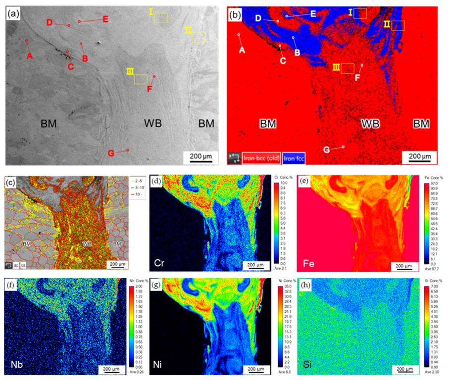
Figure 2a shows the cross-section of the WB after CO2 laser welding, and both the BM and WB are labelled in the figure. The microstructure along the longitudinal direction of the weld seam cannot clearly express the convection of the weld pool during laser welding. In contrast, the cross-section microstructure of the WB in the central portion of the weld seam presents the best effect of weld pool convection during laser welding. Therefore, the cross-section of the WB was selected in the analysis. The corresponding EBSD crystallographic and boundary misorientation maps of the WB are presented in Figure 2b,c, respectively. The shape of the WB was easily identifiable in the EBSD boundary misorientation map, as illustrated in Figure 2c. The trumpet-like WB is the result of joint melting of the laterally advanced filler wire in the laser beam and of the base materials edges, during the welding process. According to Figure 2b,c, the BM microstructure contains ferrite with a BCC structure, having grain size from about 50 to 250 μm.
There are two different structures, namely, the red BCC structure and blue FCC structure, are readily distinguishable from the WB. The blue FCC structure is the austenite. However, the red BCC structure here could be martensite or ferrite, and it will be studied later. The upper portion of the WB appears to be rich in austenite, and the middle/lower portions of the WB are primarily dominated by the BCC structure. Based on Figure 2b,c, there were few boundaries in the austenite. In contrast, the BCC structure in the WB contained a high density of high-angle boundaries (>10°). The presence of high-density boundaries in the BCC structure of the WB was very different from those in the ferrite of the BM. It is obvious that the BCC structure in the WB was not a simple ferrite.
Because of the incomplete convection of the weld pool during the laser welding, the chemical composition of the heterogeneous WB was not homogeneous after solidification. Figure 2d–h present the quantitative element mappings of Cr, Fe, Nb, Ni and Si in wt%. It is evident that WB contains the dominant austenite, which is located in the upper part of the weld, having higher concentrations of Cr, Nb and Ni compared to the middle and root zones, where the low-alloyed BCC structure predominates. Since the BM was free of these elements, the existence of Cr, Nb and Ni must have originated from the IN82 filler wire. The nickel-based IN82 filler was melted and diluted with the high Si BM during the welding. The trace of the convection vortex in the weld pool during laser welding could easily be identified from quantitative element mappings of Cr, Fe and Ni, as illustrated in Figure 2d,e,g. As shown in Figure 2e, the chemical composition of Fe in the WB was between 50 and 97 wt%. In contrast, the Ni concentration in the WB was between 0 and 35 wt%, as shown in Figure 2g. Therefore, the heterogeneous WB was an Fe-based alloy. Since the melting time was short, Cr and Ni elements did not diffuse to the Fe-rich matrix of the base material. This effect is well highlighted from the elemental distribution images in Figure 2d,g, which illustrate the trace of the melt convection driven by the keyhole mechanism in the entire laser WB in the EPMA/WDS analyses.
Based on the Fe-Ni binary alloy phase diagram, Ni is completely soluble in austenite at elevated temperatures, but in ferrite the maximum solubility of Ni is only 2 wt% Ni below 200 °C [20]. Table 1 shows quantitative chemical analyses of selected positions, labelled A~G in Figure 1a,b. Position A is the BM, with a chemical composition of 0.5 Al, 96.7 Fe, 0.1 Mn and 2.6 Si in wt%. The chemical composition of position G in the WB is very similar to that of the BM at position A. The Ni concentration at position G is as low as 0.7 wt%, well below the maximum solubility of the Ni in the ferrite [20]. It was deduced that there were a few resolidified ferrite grains in the WM. Position B and E are austenite alloyed with 26.4 and 28.7 wt% Ni, respectively. In contrast, positions C, D and F are the BCC structure in the WB. The BCC structure in the WM is featured with high-density boundaries, as demonstrated in Figure 2c. As shown in Table 1, the range of Ni concentration in the BCC structure is between 5.1 and 13.2 wt%. Both the high-density boundaries and the wide range of Ni concentrations in the BCC structure exclude the possibility that simple ferrite was the BCC structure in the WB.
The complete melting of the IN-82 filler wire and the BM in the weld pool was achieved upon laser irradiation. Strong convection of the weld pool resulted in the mixing of the various elements between the filler wire and BM. However, the characteristics of extremely short interaction time during the laser welding resulted in incomplete mixing of the filler wire and the BM in the weld pool. The dilution of the heterogeneous WB was not homogeneous after solidification [14]. Therefore, the phase/structure of the WB was not uniformly distributed after solidification. According to the aforementioned results, the redistribution of Ni in the WB was mainly driven by convection and dilution of the BM into the weld pool, and it was strongly related to the formation of the phase/structure of the WB [14].
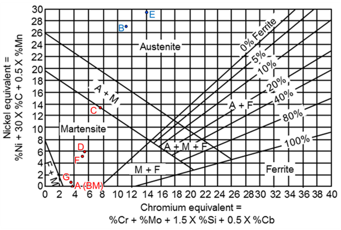
The Schaeffler diagram has been successfully applied in welding many stainless steels [21,22,23,24,25,26,27]. The phase/structure prediction of the laser weldment for many Fe-based alloys has also been reported [28,29,30]. When the laser welding is performed, the Schaeffler diagram, consisting of the chromium equivalent (= %Cr + %Mo + 1.5 %Si + 0.5 %Nb) and nickel equivalent (= %Ni + 30 %C + 0.5 %Mn), can be used to predict the microstructure of the WB according to the ratio of Ni/Cr equivalents [21,22]. In this study, the Schaeffler diagram was used to predict the BCC structure of the WB. The WDS quantitative chemical analysis results of the cross-section at positions A ~ G, shown in Table 1, were used to calculate the Cr and Ni equivalents, and the Cr/Ni equivalents were marked on the Schaeffler diagram, as shown in Figure 3 [10]. According to Figure 3, positions B and E in Figure 2b were austenite, marked with blue dots, and positions C, D and F in Figure 2b were martensite, marked by red dots. The martensite area shown in the Schaeffler diagram has a wide range of Cr/Ni equivalents. In Figure 2c, the BCC structure has a very high boundary density, which is also in line with the characteristics of martensite. The result of the EBSD crystal structure analyses were consistent with the Schaeffler diagram. It can be inferred that the BCC structure of the WB was primarily composed of martensite. It is worth mentioning that position A was BM that neither melted nor solidified during the laser welding. Therefore, it was ferrite stabilized by 2.6wt% Si without martensitic transformation.
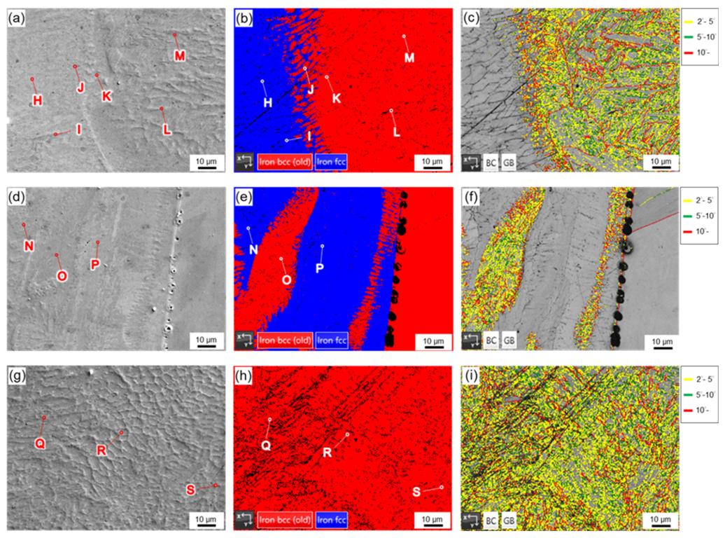
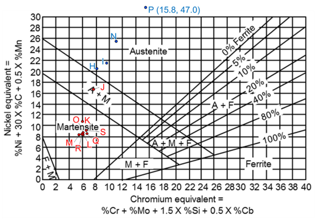
Figure 4 presents EPMA SEIs, EBSD crystallographic and boundary misorientation maps of selected areas I, II and III in the cross-section of the WB displayed in Figure 2a,b at higher magnification. In Figure 2b, two structures are visible in areas I and II. Area III is mainly composed of the BCC structure. Based on the boundary misorientation maps illustrated in Figure 4c,f,i, the BCC structure had a high density of boundaries above 2o, even at higher magnification. Table 2 presents the quantitative chemical analyses of positions H~S in Figure 4. Both Cr/Ni equivalents can be calculated according to Table 2. Figure 5 shows the Schaeffler diagram of the WB cross-section at positions H~S marked in Figure 4 [10]. According to Table 2 and Figure 4b,e and Figure 5, positions, H, I and N were austenite with high Ni concentrations of 20.1, 21.2 and 24.9 wt%, respectively. The chemical composition at position P in wt% was 0.2 Al, 13.1 Cr, 34.8 Fe, 2.4 Mn, 1.5 Nb, 45.8 Ni and 1.3 Si. This result is beyond the range of the Schaeffler diagram due to the high Ni equivalent of 47. The high Ni concentration of 45.8 wt% was resulted from low dilution of the BM in area II (Figure 2b) [14]. The accumulation of nickel-based filler in the top region of the WB was caused by the nature of insufficient mixing between the filler wire and BM in the weld pool during the laser welding.
The BCC structure was identified at the positions K, L, and M (Figure 4b), O (Figure 4e), Q, R, and S (Figure 4h), which was in the martensite region of the Schaeffler diagram, as demonstrated in Figure 5. It is noteworthy that the red dot J in Figure 4b is located in the region where martensite and austenite coexist. This is consistent with the region of A + M in the Schaeffler diagram (Figure 5). EBSD crystallographic analyses, EPMA quantitative chemical analyses and the Schaeffler diagram were all in good agreement.
Based on Table 2, the Ni concentration played an important role in the formation of austenite and martensite in the WB. Austenite was formed if the Ni concentration was above 20 wt%. In contrast, a wide range of Ni concentrations was observed in the martensite. The Ni concentration at position F was 5.1 wt% (Figure 2b), and the Ni concentration at position J was as high as 16.4 wt%. According to Figure 2g, the quantitative mapping of Ni best represents the strong convection of the weld pool in the keyhole mode in laser welding [31].
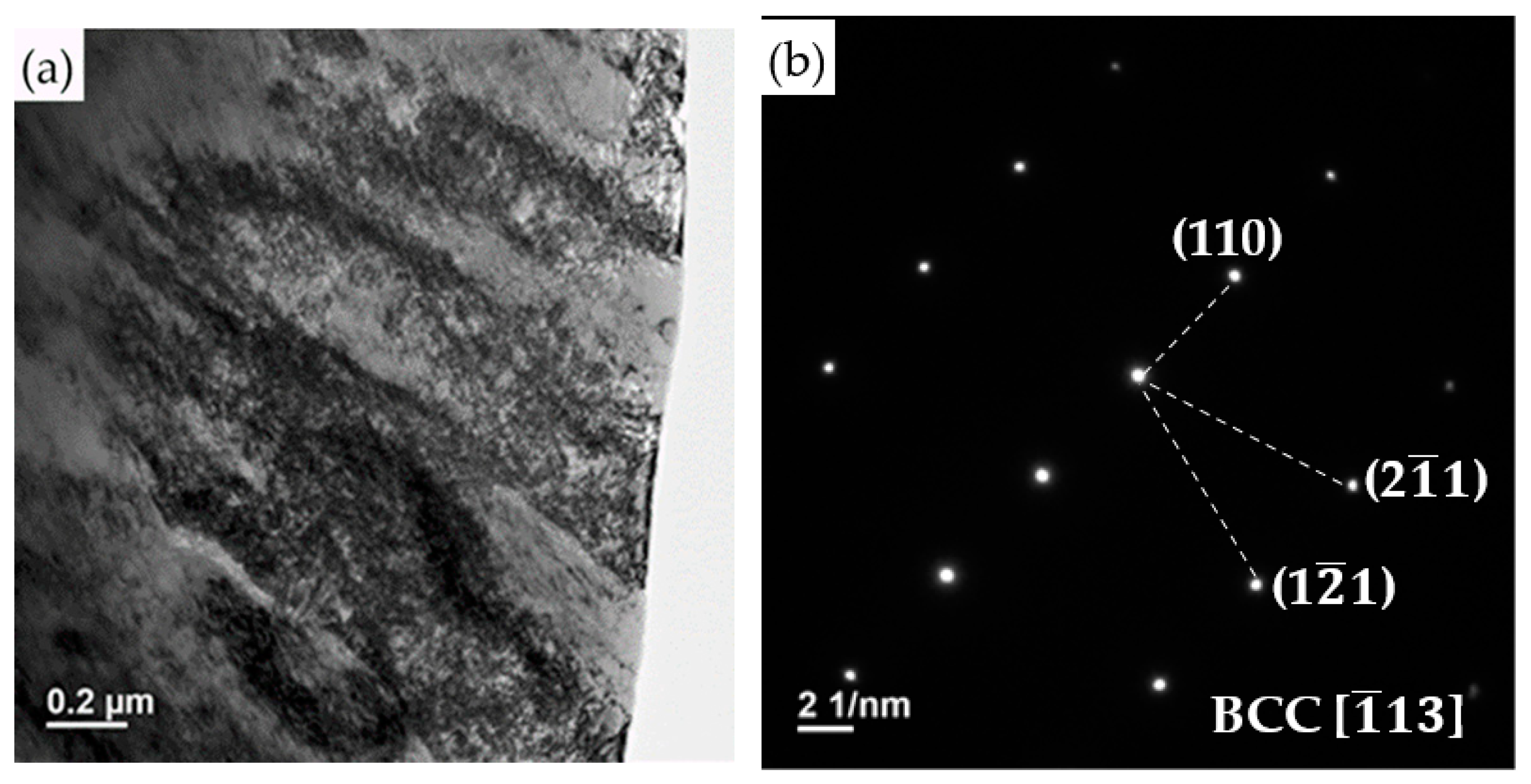
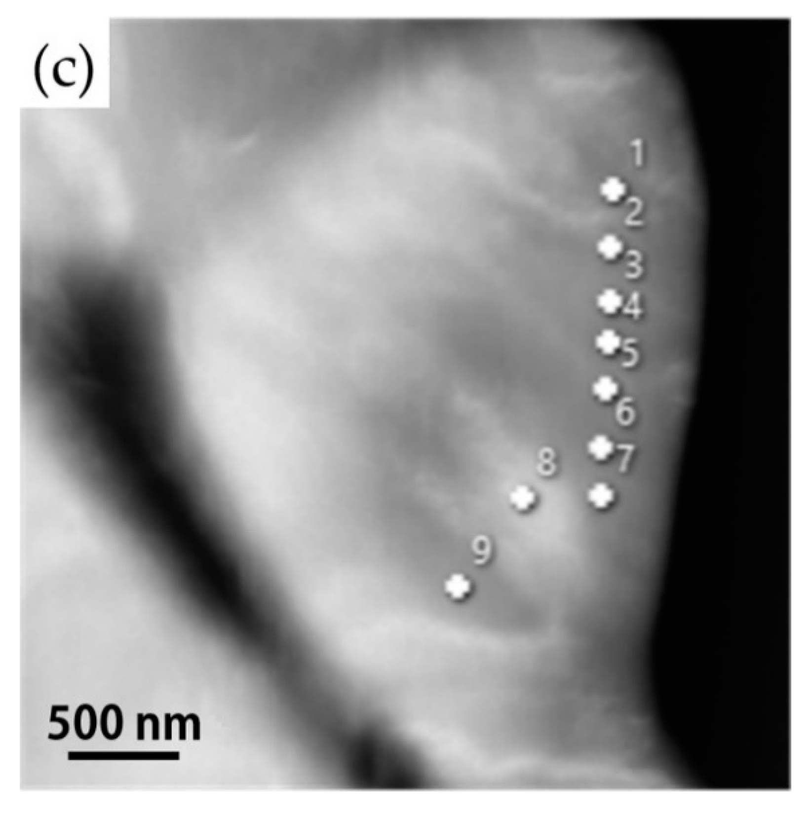
Figure 6a shows a bright field (BF) image of the BCC structure, and the selected area diffraction pattern (SADP) is also provided in Figure 6b. Lath martensite is visible in Figure 6a. There is a notable absence of retained austenite along the lath boundaries of martensite. Figure 6c shows a high-angle annular dark-field (HAADF) image, and the EDS chemical analysis results at positions 1–9 are listed in Table 3. The Ni concentrations in the table are between 8.5 and 9.5 in wt%. These are consistent with the aforementioned results indicating that the martensite will be formed if the Ni concentration is between 5.1 and 16.4 wt%. The STEM/EDS analysis results demonstrate that the BCC structure with a high density of boundaries in the EBSD analysis was martensite.
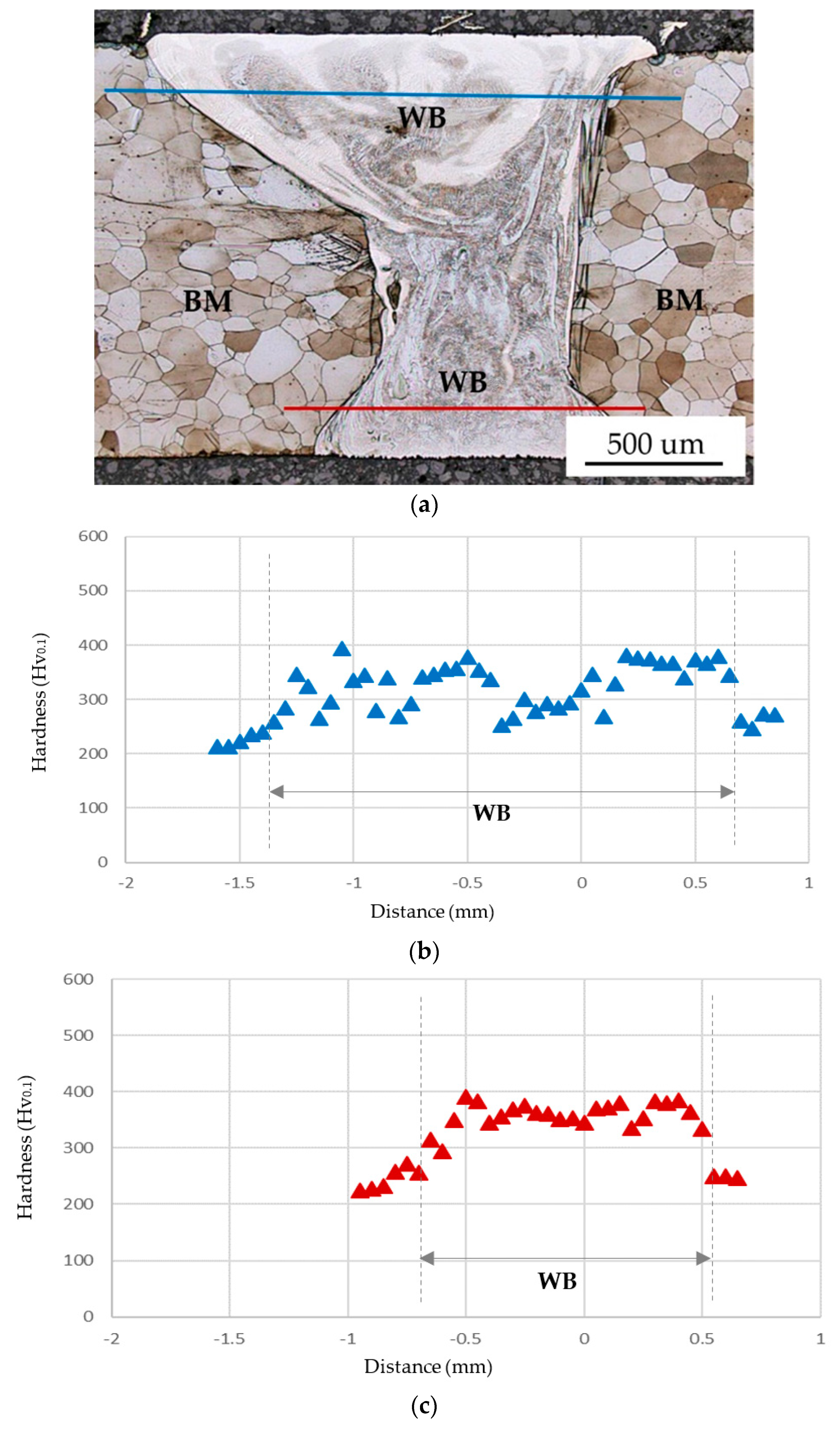
Figure 7 shows the Vickers microhardness measurement results of the WB. In Figure 7a, the white area in the WB is austenite, and the gray area in the WB is martensite. There are two lines in the cross-section of the WB. The hardness measurements were performed from the left to the right along the top blue line and bottom red line, respectively. The distance between two measurements was set at 5 μm. In Figure 7b, the top blue line passed white austenite and gray martensite areas. The hardness of the base metal is approximately 210 Hv0.1. The hardness of martensite ranges from 350 to 400 Hv0.1. In contrast, the hardness of austenite is between 250 and 300 Hv0.1. In Figure 7c, the bottom red line primarily passed the gray martensite area in the WB with the hardness above 350 Hv0.1. The hardness distribution in the WB is not uniform due to different combinations of martensite and austenite in the WB. The martensite has the highest hardness in the WB in comparison with the austenite and ferrite. It is deduced that the combination of hard martensite and soft austenite/ferrite in the WB is beneficial to its strength.
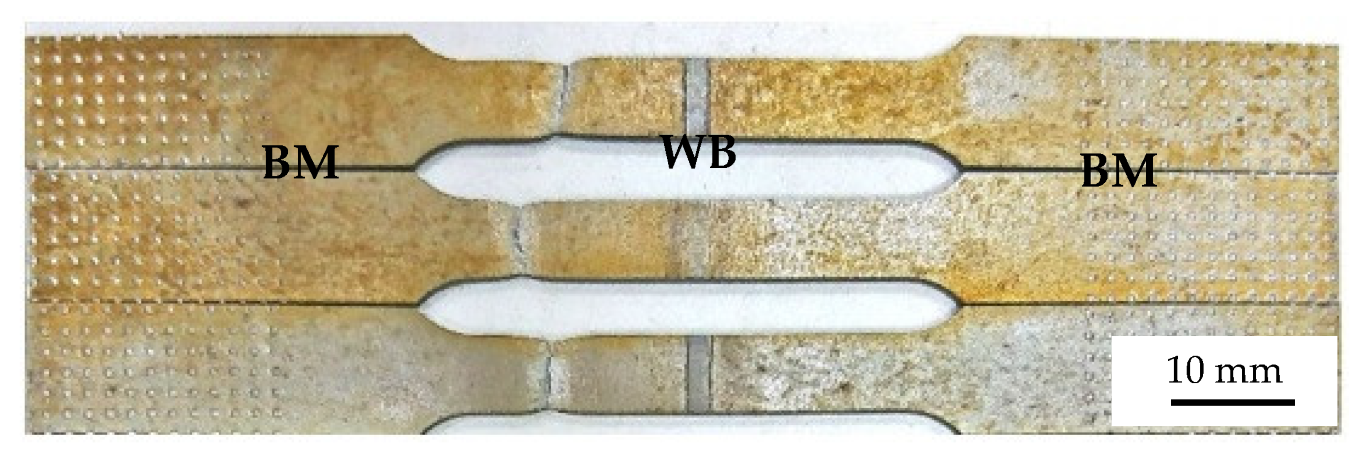
Figure 8 shows three tensile test specimens perpendicular to the WB after tensile tests. The BM and WB are labelled in the figure. All specimens were fractured in the BM with the tensile strengths between 490 and 500 MPa. The necking of BM is observed in all three specimens. In contrast, three WBs shown in Figure 8 are free of necking after tensile tests. It is obvious that the combination of martensite and austenite/ferrite in the WB is much stronger than the ferrite of BM.

4. Conclusions

The IN82 filler wire and high-silicon steel WB using a high-power CO2 laser has been investigated with the aid of EPMA/WDS quantitative chemical analysis, FESEM/EBSD crystallographic analysis, and STEM/EDS structure analysis. Important conclusions are shown below:
  • The heterogeneous WB was mainly composed of austenite in the upper portion and martensite in the middle and bottom portions due to incomplete mixing of the weld pool during laser welding. The trace of convection in the entire laser weld pool was successfully identified from the quantitative Ni mapping in the EPMA analysis.
  • The formation of martensite and austenite was determined by the Ni concentration of the WB. The austenite was alloyed with Ni above 20.1 wt%. The austenite was unstable and transformed into martensite if the Ni concentration was decreased below 16.4 wt%. Additionally, there was no retained austenite observed at the lath boundary of martensite.
  • The austenite in the WB was soft with the hardness range between 250 and 300 Hv0.1. In contrast, the martensite had the highest hardness between 350 and 400 Hv0.1. The high-silicon BM had the lowest hardness of 210 Hv0.1. Therefore, the combination of high-hardness martensite and austenite in the heterogeneous WB was much stronger than the ferrite BM. In the tensile test, all specimens were fractured in the BM with the tensile strengths between 490 and 500 MPa, and the necking of the BM was observed after the tensile test. The application of the IN82 filler wire in laser welding a high-silicon steel plate can successfully obtain a robust WB.

Author Contributions

Experiment, M.-F.C., T.-Y.L., and P.-H.C.; formal analysis, M.-F.C.; writing—original draft preparation, R.-K.S.; writing—review and editing, M.-F.C. and R.-K.S.; funding acquisition, R.-K.S. All authors have read and agreed to the published version of the manuscript.

Funding

This research was funded by the Ministry of Science and Technology, ROC (Contract No. MOST 109-2221-E-002-042-MY3).

Institutional Review Board Statement

Not applicable.

Informed Consent Statement

Not applicable.

Data Availability Statement

Not applicable.

Acknowledgments

Thanks to C.S. Lin, Y.T. Lee, H.C. Lin and C.Y. Kao of Instrumentation Center, National Taiwan University for FGSEM/EBSD and EPMA/WDS analyses. The authors gratefully acknowledge the use of JEOL JEM-2100F Cs STEM of MOST 110-2731-M-006-001 belonging to the Core Facility Center of National Cheng Kung University.

Conflicts of Interest

The authors declare no conflict of interest.

Nomenclature

BCCBody-centered cubic
BEIBack-scattered electron image
BFBright field
BMBase metal
EBSDElectron back-scattered diffraction
EDSEnergy-dispersive spectrometer
EPMAElectron probe micro-analyzer
FCCFace-centered cubic
FESEMField emission scanning electron microscope
HAADFHigh-angle annular dark-field
IN82Inconel 82
SADPSelected area diffraction pattern
SEISecondary electron imaging
STEMScanning transmission electron microscope
WBWeld bead
WDSWavelength dispersive spectrometer

References

  1. Greifzu, M.; Tkachov, R.; Stepien, L.; Lopez, E.; Bruckner, F.; Leyens, C. Laser treatment as sintering process for dispenser printed bismuth telluride based paste. Materials 2019, 12, 3453. [Google Scholar] [CrossRef] [PubMed] [Green Version]
  2. Lee, D. Experimental investigation of laser ablation characteristics on nickel-coated beryllium copper. Metals 2018, 8, 211. [Google Scholar] [CrossRef] [Green Version]
  3. Ahmed, S.H.; Mian, A. Influence of material property variation on computationally calculated melt pool temperature during laser melting process. Metals 2019, 9, 456. [Google Scholar] [CrossRef] [Green Version]
  4. Biffi, C.A.; Bassani, P.; Carnevale, M.; Lecis, N.; Loconte, A.; Previtali, B.; Tuissi, A. Effect of laser microcutting on thermo-mechanical properties of NiTiCu shape memory alloy. Met. Mater. Int. 2014, 20, 83–92. [Google Scholar] [CrossRef]
  5. Mohammed, G.R.; Ishak, M.; Ahmad, S.N.A.S.; Abdulhadi, H.A. Fiber laser welding of dissimilar 2205/304 stainless steel plates. Metals 2017, 7, 546. [Google Scholar] [CrossRef] [Green Version]
  6. Villar, R. Laser cladding. J. Laser Appl. 1999, 11, 64. [Google Scholar] [CrossRef]
  7. Gu, D.D.; Meiners, W.; Wissenbach, K.; Poprawe, R. Laser additive manufacturing of metallic components: Materials, processes and mechanisms. Int. Mater. Rev. 2012, 57, 133–164. [Google Scholar] [CrossRef]
  8. Wu, X. A review of laser fabrication of metallic engineering components and of materials. Mater. Sci. Technol. 2007, 23, 631–640. [Google Scholar] [CrossRef]
  9. Mujumdar, J.D.; Manna, I. Laser material processing. Int. Mater. Rev. 2011, 56, 341–388. [Google Scholar] [CrossRef]
  10. Kou, S. Welding Metallurgy, 2nd ed.; John Wiley & Sons: New York, NY, USA, 2003. [Google Scholar]
  11. Lippold, J.C. Welding Metallurgy and Weldability; John Wiley & Sons: New York, NY, USA, 2015. [Google Scholar]
  12. Saunders, F.I.; Wagoner, R.H. Forming of tailor-welded blanks. Metall. Mater. Trans. A 1996, 27, 2605–2616. [Google Scholar] [CrossRef] [Green Version]
  13. Zambon, A.; Ferro, P.; Bonollo, F. Microstructural, compositional and residual stress evaluation of CO2 laser welded superaustenitic AISI 904L stainless steel. Mater. Sci. Eng. A 2006, 424, 117–127. [Google Scholar] [CrossRef]
  14. Chiang, M.F.; Lo, T.Y.; Chien, P.H.; Chi, C.H.; Chang, K.C.; Yeh, A.C.; Shiue, R.K. The dilution effect in high-power disk laser welding the steel plate using a nickel-based filler wire. Metals 2021, 11, 874. [Google Scholar] [CrossRef]
  15. Nivas, R.; Das, G.; Das, S.K.; Mahato, B.; Kumar, S.; Sivaprasad, K.; Singh, P.K.; Ghosh, M. Effect of stress relief annealing on microstructure & mechanical properties of welded joints between low alloy carbon steel and stainless steel. Metall. Mater. Trans. A 2017, 48, 230–245. [Google Scholar]
  16. Chen, Z.R.; Lu, Y.H. TEM observation of martensite layer at the weld interface of an A508III to Inconel 82 dissimilar metal weld joint. Metall. Mater. Trans. A 2015, 46, 5494–5498. [Google Scholar] [CrossRef]
  17. Sireesha, M.; Albert, S.K.; Sundaresan, S. Influence of high-temperature and mechanical properties of exposure on the microstructure dissimilar metal welds between modified 9Cr-1Mo steel and alloy 800. Metall. Mater. Trans. A 2005, 36, 1495–1506. [Google Scholar] [CrossRef]
  18. Santosh, R.; Das, G.; Kumar, S.; Singh, P.K.; Ghosh, M. Experimental and computational investigation of structural integrity of dissimilar metal weld between ferritic and austenitic steel. Metall. Mater. Trans. A 2018, 49, 2099–2112. [Google Scholar] [CrossRef]
  19. Chien, P.H. The Study of High-Power CO2 Laser Welding High-Silicon Steel Plate. Master’s Thesis, National Taiwan University, Taipei, Taiwan, June 2022. [Google Scholar]
  20. Okamoto, H.; Massalski, T.B. Binary Alloy Phase Diagrams, 2nd ed.; ASM International: Materials Park, OH, USA, 1990. [Google Scholar]
  21. Guiraldenq, P.; Duparc, O.H. The genesis of the Schaeffler diagram in the history of stainless steel. Metall. Res. Technol. 2017, 114, 613. [Google Scholar] [CrossRef]
  22. Kotecki, D.J.; Siewert, T.A. WRC-1992 constitution diagram for stainless-steel weld metals—A modification of the WRC-1988 diagram. Weld. J. 1992, 71, s171–s178. [Google Scholar]
  23. Ukumoto, S.; Fujiwara, K.; Toji, S.; Yamamoto, A. Small-scale resistance spot welding of austenitic stainless steels. Mater. Sci. Eng. A 2008, 492, 243–249. [Google Scholar] [CrossRef]
  24. Jaber, H.L.; Pouranvari, M.; Marashi, S.P.H.; Alizadeh-Sh, M.; Salim, R.K.; Hashim, F.A. Dissimilar spot welding of dual phase steel/ferritic stainless steel: Phase transformations. Sci. Technol. Weld. Join. 2014, 19, 565–571. [Google Scholar] [CrossRef]
  25. Kadoi, K.; Shinozaki, K. Effect of chemical composition on susceptibility to weld solidification cracking in austenitic weld metal. Metall. Mater. Trans. A 2017, 48, 5860–5869. [Google Scholar] [CrossRef]
  26. Brandi, S.D.; Schon, C.G. A Thermodynamic study of a constitutional diagram for duplex stainless steels. J. Phase Equilibria Diffus. 2017, 38, 268–275. [Google Scholar] [CrossRef]
  27. Vashishtha, H.; Taiwade, R.V.; Khatirkar, R.K.; Ingle, A.V.; Dayal, R.K. Welding behaviour of low nickel chrome manganese stainless steel. ISIJ Int. 2014, 54, 1361–1367. [Google Scholar] [CrossRef] [Green Version]
  28. Missori, S.; Koerber, C. Laser beam welding austenitic-ferritic transition joints. Weld. J. 1997, 76, s125–s134. [Google Scholar]
  29. Landowski, M.; Swierczynska, A.; Rogalski, G.; Fydrych, D. Autogenous fiber laser welding of 316L austenitic and 2304 lean duplex stainless steels. Materials 2020, 13, 2930. [Google Scholar] [CrossRef] [PubMed]
  30. Shi, Y.L.; Wu, S.K.; Liao, H.B.; Wang, X.Y. Microstructure and mechanical properties of CLF-1/316 L steel dissimilar joints welded with fiber laser welding. J. Manuf. Process. 2020, 54, 318–327. [Google Scholar] [CrossRef]
  31. Hao, Z.; Chen, H.; Jin, X.; Liu, Z. Comparative study on the behavior of keyhole in analogy welding and real deep penetration laser welding. Materials 2022, 15, 9001. [Google Scholar] [CrossRef] [PubMed]
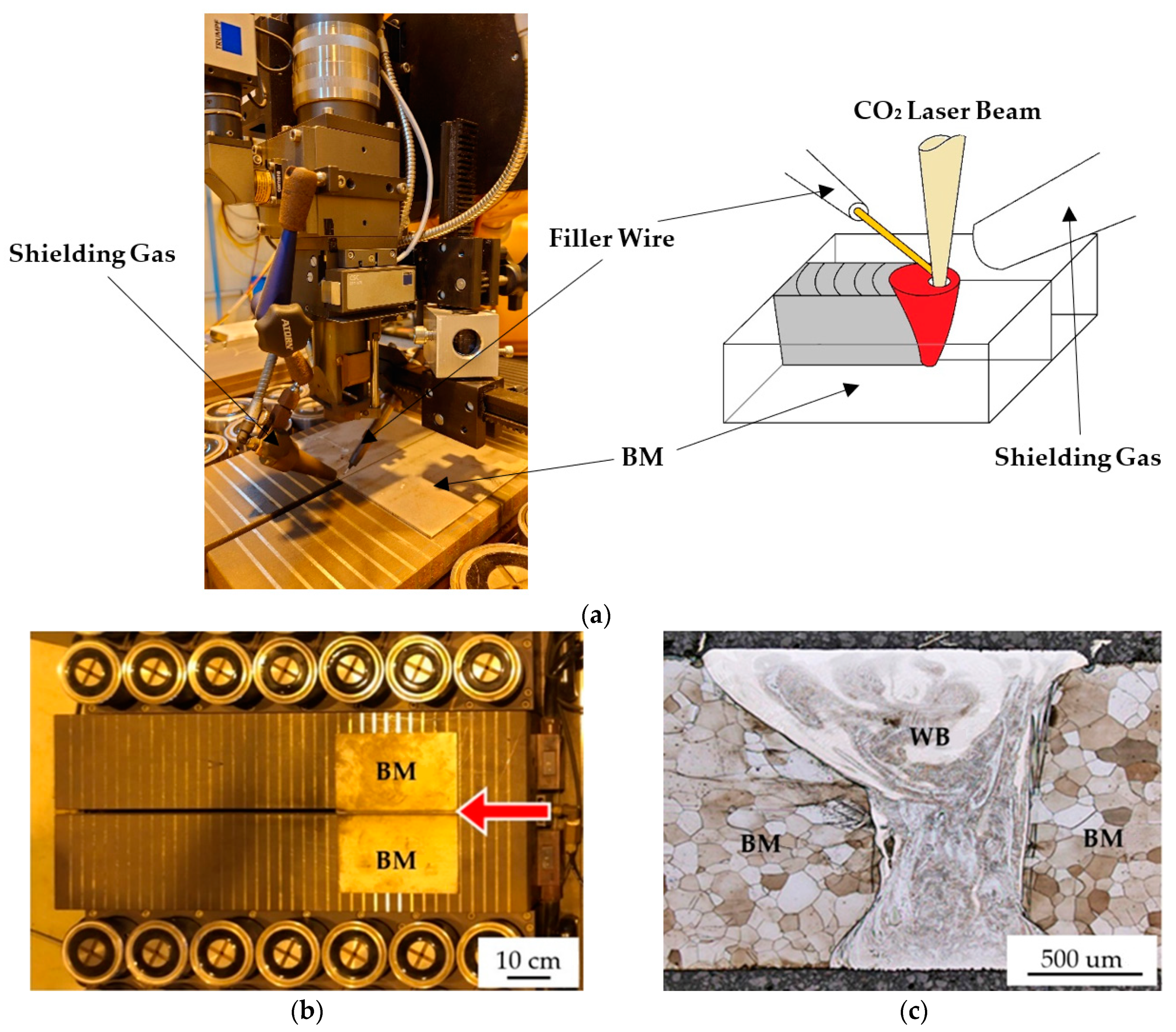
Figure 1. (a) The laser welding station and a schematic diagram of laser welding, (b) top view of the specimen after laser welding, and (c) the cross-section of the WB.
Metals 13 00234 g001
Figure 2. Cross-section images of the high-power CO2 laser WB: (a) EPMA SEI image; FESEM EBSD (b) crystallographic map; (c) boundary misorientation map; EPMA WDS quantitative element mappings in wt%: (d) Cr, (e) Fe, (f) Nb, (g) Ni, (h) Si.
Metals 13 00234 g002
Figure 3. The Schaeffler diagram of the WB cross-section at positions A~G in Figure 2ab [10].
Metals 13 00234 g003
Figure 4. EPMA SEIs, EBSD crystallographic and boundary misorientation maps of selected areas in the cross-section of the weld bead displayed in Figure 1a at higher magnification: (a–c) area I, (d–f) area II and (g–i) area III.
Metals 13 00234 g004
Figure 5. The Schaeffler diagram of the WB cross-section at positions H~S shown in Figure 4 [10].
Metals 13 00234 g005
Figure 6. STEM analysis result of the BCC structure: (a) BF image, (b) SADP with the zone axis of [ 1 ¯ 13], (c) HAADF image and EDS chemical analyses at positions 1–9.
Metals 13 00234 g006aMetals 13 00234 g006b
Figure 7. Vickers microhardness measurements of the WB: (a) the cross-section of the WB, (b) microhardness values along the top blue line in Figure 7a, and (c) microhardness values along the bottom red line in Figure 7a.
Metals 13 00234 g007
Figure 8. Tensile test specimens perpendicular to the WB after tensile tests.
Metals 13 00234 g008
Table 1. Quantitative chemical analyses of positions A~G in Figure 1a,b.
Element/wt%AlCrFeMnNbNiSiPhase/Structure
A0.50.096.70.10.00.02.6ferrite (BM)
B0.47.160.91.31.026.42.5austenite
C0.43.679.30.40.413.22.5BCC
D0.41.788.90.20.25.82.4BCC
E0.56.755.01.63.028.73.8austenite
F0.41.689.90.20.25.12.4BCC
G0.40.196.00.10.00.72.5ferrite (WB)
Table 2. Quantitative chemical analyses of positions H~S in Figure 4.
Element/wt%AlCrFeMnNbNiSiPhase/Structure
H0.35.971.30.40.220.11.3austenite
I0.36.368.70.60.421.22.1austenite
J0.35.075.60.50.216.41.7BCC
K0.33.383.30.30.110.71.8BCC
L0.42.485.80.20.38.22.4BCC
M0.42.088.50.20.26.22.3BCC
N0.47.062.11.31.524.92.2austenite
O0.42.685.60.40.38.42.2BCC
P0.213.134.82.41.545.81.3---
Q0.42.685.20.30.38.32.5BCC
R0.42.785.90.20.28.32.0BCC
S0.42.784.60.30.29.02.4BCC
Table 3. STEM/EDS chemical analyses at positions 1~9 in Figure 6c.
Element/wt%AlCrFeMnNbNiSi
10.44.383.40.50.19.52.0
20.44.483.50.50.09.31.9
30.44.283.70.80.48.81.8
40.44.584.10.60.18.51.9
50.54.183.60.60.49.01.9
60.44.184.20.60.48.51.7
70.34.184.30.50.38.81.8
80.44.284.00.50.38.61.9
90.44.284.20.60.48.51.8
Disclaimer/Publisher’s Note: The statements, opinions and data contained in all publications are solely those of the individual author(s) and contributor(s) and not of MDPI and/or the editor(s). MDPI and/or the editor(s) disclaim responsibility for any injury to people or property resulting from any ideas, methods, instructions or products referred to in the content.