Abstract
The behavior of the EK-181 low-activation ferritic-martensitic reactor steel (Fe–12Cr–2W–V–Ta–B) in the states with different levels of strength and plastic properties after traditional heat treatment (THT) and after high-temperature thermomechanical treatment (HTMT) in the temperature range from −196 to 25 °C, including the range of its cold brittleness (ductile–brittle transition temperature, DBTT) is studied. The investigations are carried out using non-destructive acoustic methods (internal friction, elasticity) and transmission and scanning electron microscopy methods. It is found that the curves of temperature dependence of internal friction (the vibration decrement) of EK-181 steel after THT and HTMT are similar to those of its impact strength. Below the ductile–brittle transition temperature, it is characterized by a low level of dislocation internal friction. The temperature dependence curves of the steel elastic modulus increase monotonically with the decreasing temperature. In this case, the value of Young’s modulus is structure-sensitive. A modification of the microstructure of EK-181 steel as a result of HTMT causes its elastic modulus to increase, compared to that after THT, over the entire temperature range under study. The electron microscopic studies of the steel microstructure evolution near the fracture surface of the impact samples (in the region of dynamic crack propagation) in the temperature range from −196 to 100 °C reveal the traces of plastic deformation (increased dislocation density, fragmentation of the martensitic structure) at all of the temperatures under study, including those below the cold brittleness threshold of EK-181 steel.
Keywords:
low-activation ferritic-martensitic steel EK-181; internal friction; Young’s modulus; ductile–brittle transition temperature; cold-brittleness regularities; fracture mechanism; deformed microstructure; high-temperature thermomechanical treatment; scanning electron microscopy; transmission electron microscopy 1. Introduction
Low-activation ferritic-martensitic steels with 9–12% chromium are thought to be the priority structural materials for fast neutron and thermonuclear reactors [1,2,3]. A significant problem with such materials is their cold brittleness (embrittlement and brittle fracture at low temperatures) [3,4]. The tendency to cold embrittlement is a distinctive property of metals and alloys with a body-centered cubic (BCC) lattice (with the exception of Ta) [3,4,5]. It is well known that face-centered cubic (FCC) alloys do not undergo a ductile–brittle transition when the test temperature is reduced. The reasons for this behavior of materials with different types of crystal lattices currently remain a subject of debate [3,4,5,6,7].
Earlier [8,9,10], we discussed the features of the microstructure and mechanical behavior of the EK-181 promising low-activation 12% chromium ferritic-martensitic reactor steel (Fe–12Cr–2W–V–Ta–B) after a traditional heat treatment (THT, quenching + high tempering) and a high-temperature thermomechanical treatment (HTMT, with deformation in the temperature region of metastable austenite) under static and dynamic loads. The use of HTMT is mainly aimed at improving the high-temperature strength properties of ferritic-martensitic steels, including those under creep conditions [5,9,10,11,12,13,14]. It is necessary to expand the range of their operating temperatures (increasing the upper limit) in the reactor core. It has been shown [9] that the HTMT mode causes the steel grain and carbides refinement. It provides a simultaneous increase (by ≈20%) in the yield strength of EK-181 steel in the temperature range from −196 to 800 °C and its impact strength (with a decrease in the ductile–brittle transition temperature).
In this work, the main attention is focused on the study of the regularities and mechanisms of the EK-181 low-temperature embrittlement of ferritic-martensitic steel in the temperature range from −196 to 100 °C.
According to [3,15], the mechanisms for the formation of cold brittleness in metals are based on dislocations and determine the cold brittleness as a structural multistage process. The study of internal friction in metals is an effective method for determining the viscous mobility of dislocations and estimating the coefficient of their viscous drag [16,17]. The magnitude of the vibration decrement (internal friction) is largely determined by the dislocation mobility, which in turn depends on many factors (temperature, strain rate, phase and elemental composition of the material, its microstructure, etc.) [18].
In connection with the above, in our opinion, it is of interest to comprehensively study the phenomenon of low-temperature embrittlement of EK-181 steel (as a representative of BCC materials) using the non-destructive acoustic method of internal friction and the regularities of plastic deformation and fracture depending on the temperature of mechanical tests (in the region of low temperatures) in the states with different levels of strength and plastic properties (after THT and HTMT). For this purpose, we studied the temperature dependence of the Young’s modulus of EK-181 steel and the vibration decrement using an acoustic method, as well as the features of its deformed microstructure near the fracture surface of impact samples destroyed in the temperature range from −186 to 100 °C, where its ductile–brittle transition occurs.
2. Materials and Methods
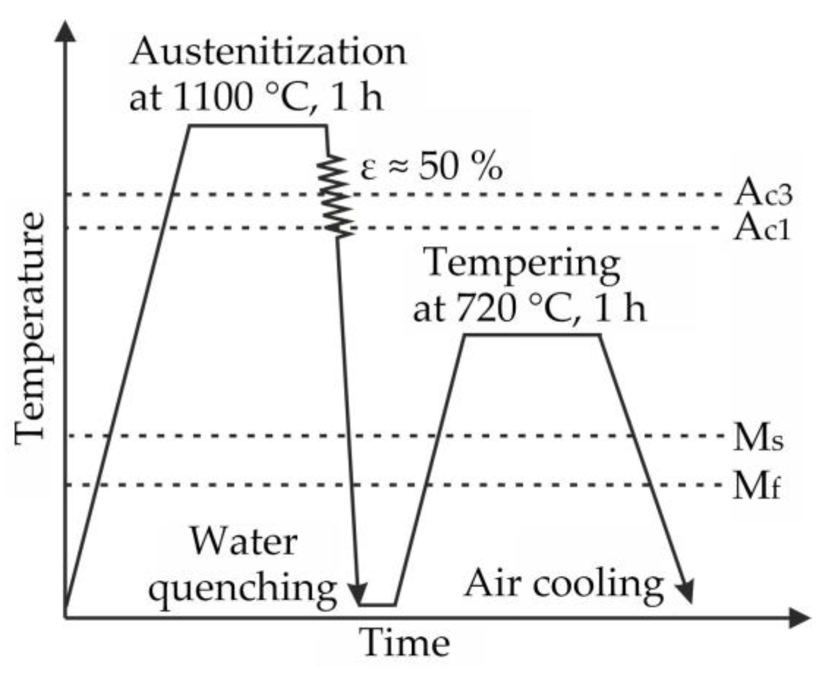
The elemental composition of the EK-181 steel is presented in Table 1. A traditional heat treatment (THT) included quenching from T = 1100 °C (holding for 1 h) and tempering at T = 720 °C (for 3 h). A high-temperature thermomechanical treatment (HTMT) was carried out according to the following regime (Figure 1): heating to T = 1100 °C (followed by holding for 1 h) + hot plastic deformation by rolling in the austenite region to a value of ε ≈ 50% (mill rolls were at room temperature) + quenching in water + tempering at 720 °C (exposure for 1 h) [9].

Table 1.
Elemental composition of EK-181 steel (wt.%, base Fe) [9].
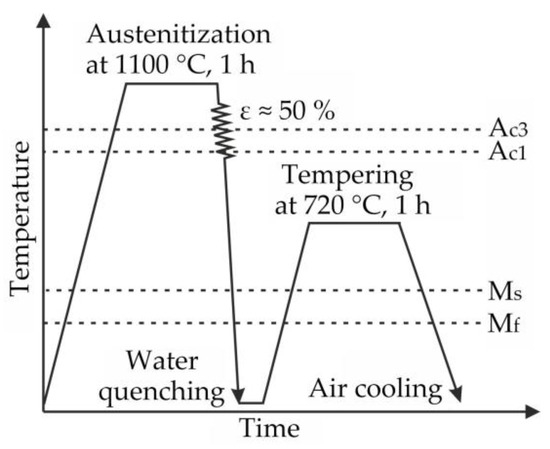
Figure 1.
Diagram of high-temperature thermomechanical treatment of EK-181 steel [9].
An investigation of internal friction of the EK-181 steel samples after THT and HTMT by the non-destructive acoustic method was carried out using the resonant method of a composite piezoelectric vibrator. A detailed description of the method can be found in [17]. The samples for ultrasonic testing had the shape of smooth rectangular rods with a cross-section of 1 × 5 mm2 and a length of l = 28 mm.
For the investigation of the deformation pre-history influence on the acoustic properties, the specimens were deformed plastically (via an introduction of fresh dislocations) by three-point bending on an Instron 5582 testing machine (INSTRON, Norwood, MA, USA). The distance between the supports of the deforming device was 18 mm. After deformation, the residual deflection in the middle of the sample reached ≈0.5 mm. The measurements were carried out on the initial samples (after THT and HTMT) and on the plastically bent samples.
The acoustic studies were carried out as follows. The temperature dependence of the logarithmic decrement δi(T) and Young’s modulus E(T) was measured when the undeformed sample was cooled from 25 to −196 °C. The natural frequency of longitudinal vibrations of the samples was f ≈ 100 kHz. The vibration amplitude in this experiment was almost constant (1 × 10⁻⁶, with an error of ≤5%). Its value was in the range of the amplitude-independent absorption over the entire temperature range under consideration. The cooling rate was ≈ 2 °C/min. After heating, the sample was deformed at room temperature by the three-point bending, then the measurements of δi(T) and E(T) were repeated. Young’s modulus E was determined as E = 4 × ρ × l2 × f2 (here, ρ is the sample density).
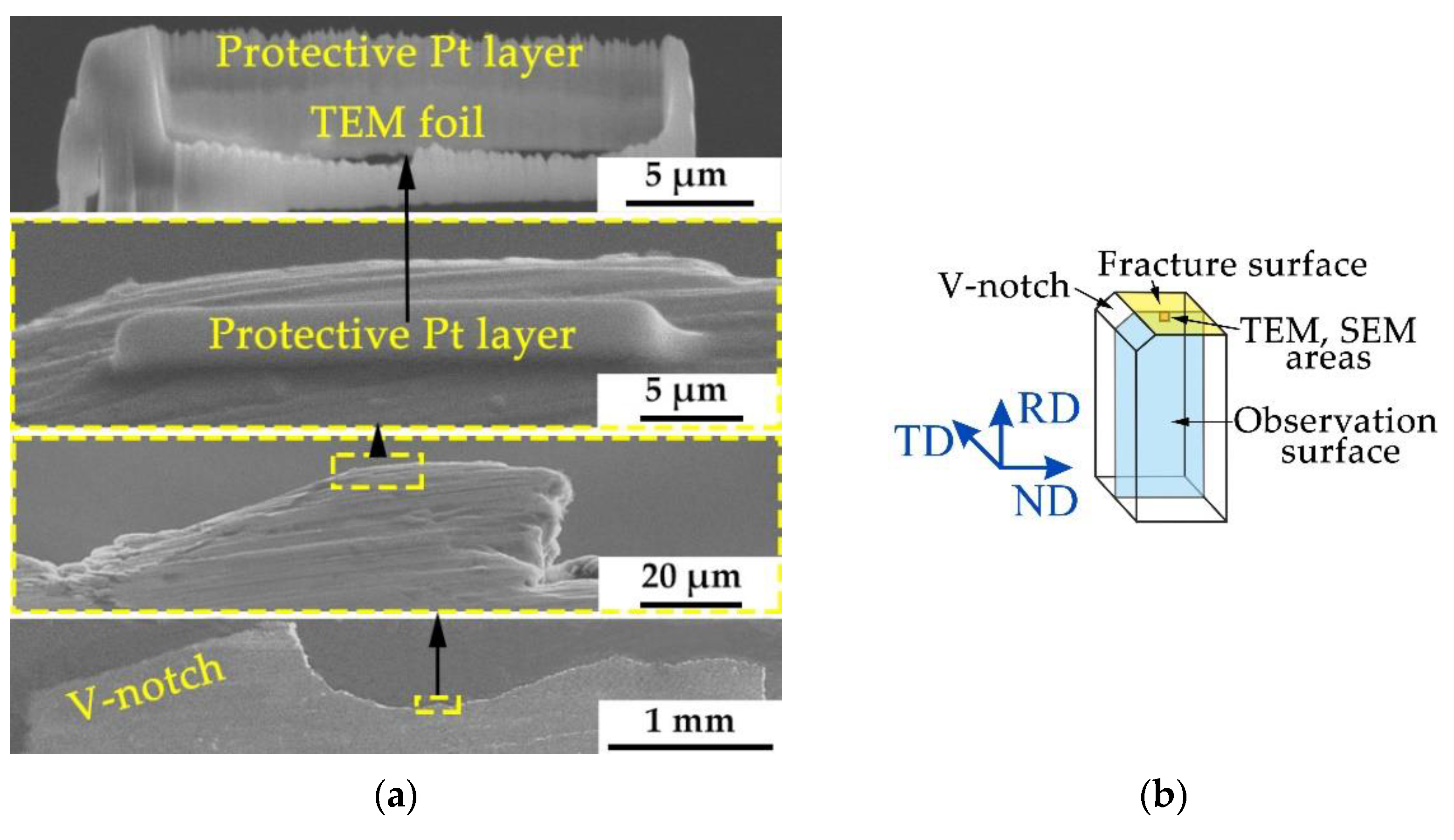
The investigations of the deformed steel microstructure (after THT and HTMT) near the fracture surface of the samples (small 3 × 4 × 27 mm3 Charpy-type samples with a V-notch) after impact tests in the temperature range from −186 to 100 °C using transmission electron microscopy (TEM) were carried out on a JEOL JEM-2100 microscope (JEOL Ltd., Akishima, Tokyo, Japan) at an accelerating voltage of 200 kV. It has an X-ray energy-dispersive microanalysis system with an INCA energy detector. The results of impact tests are presented in [9]. The dislocation density was calculated by the secant method. The preparation of thin foils for such studies was carried out using a Hitachi FB-2100 focused ion beam (FIB) system, which allows samples to be cut from the required area of the material (in our case, directly below the fracture surface of impact samples) with sufficient accuracy. The sample cutting diagram is shown in Figure 2a (the pre-impact sample was cut in half along the long side, then foil was prepared from its central part, Figure 2b). To protect the edge of the foil from destruction, a Pt layer was applied to it.
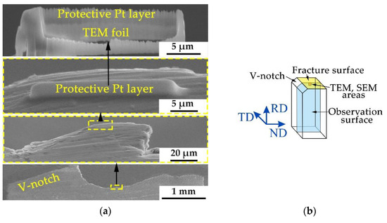
Figure 2.
Scheme of TEM foil preparation near the central part of the fracture surface of the samples after impact testing with an FIB system (a), half of a fractured Charpy steel sample with a V-notch, with TEM and SEM study areas marked (b). For a sample after HTMT: RD—rolling direction, ND—normal direction, TD—transverse direction.
The deformed microstructure near the fracture surface of the steel EK-181 impact sample (Figure 2b) after testing at −50 °C was also studied by the electron backscatter diffraction method (EBSD) using an Apreo 2 S SEM (ThermoFisher Scientific, Waltham, MA, USA) equipped with a Field Emission Gun (FEG) and a Pegasus Integrated EDS-EBSD system with the Octane Elect Super and Velocity Super detectors (EDAX). The accelerating voltage was 15 kV, and the scanning step was 50 nm.
The samples for the SEM study were mechanical and ion polished. Ion milling was performed in a Technoorg Linda SEMPrep 2 system (Technoorg Linda Co., Ltd., Budapest, Hungary).
The microstructure analysis was carried out by the EDAX Apex software (version 2.1). Low-angle boundaries (LAB) are the boundaries with a misorientation angle of 2° < θ ≤ 15°. High-angle boundaries (HAB) are those with a misorientation angle θ > 15°.
The grain size was determined as the value of the equivalent circle diameter (ECD) with HAB. Here, this parameter correlates with the sizes of martensite blocks and ferrite grains, since they are the smallest structural units separated from each other mainly by HAB.
The fracture surfaces of the samples after the impact tests in the temperature range from −186 to 100 °C were studied by scanning electron microscopy using an Apreo 2 S SEM.
3. Results
3.1. Internal Friction
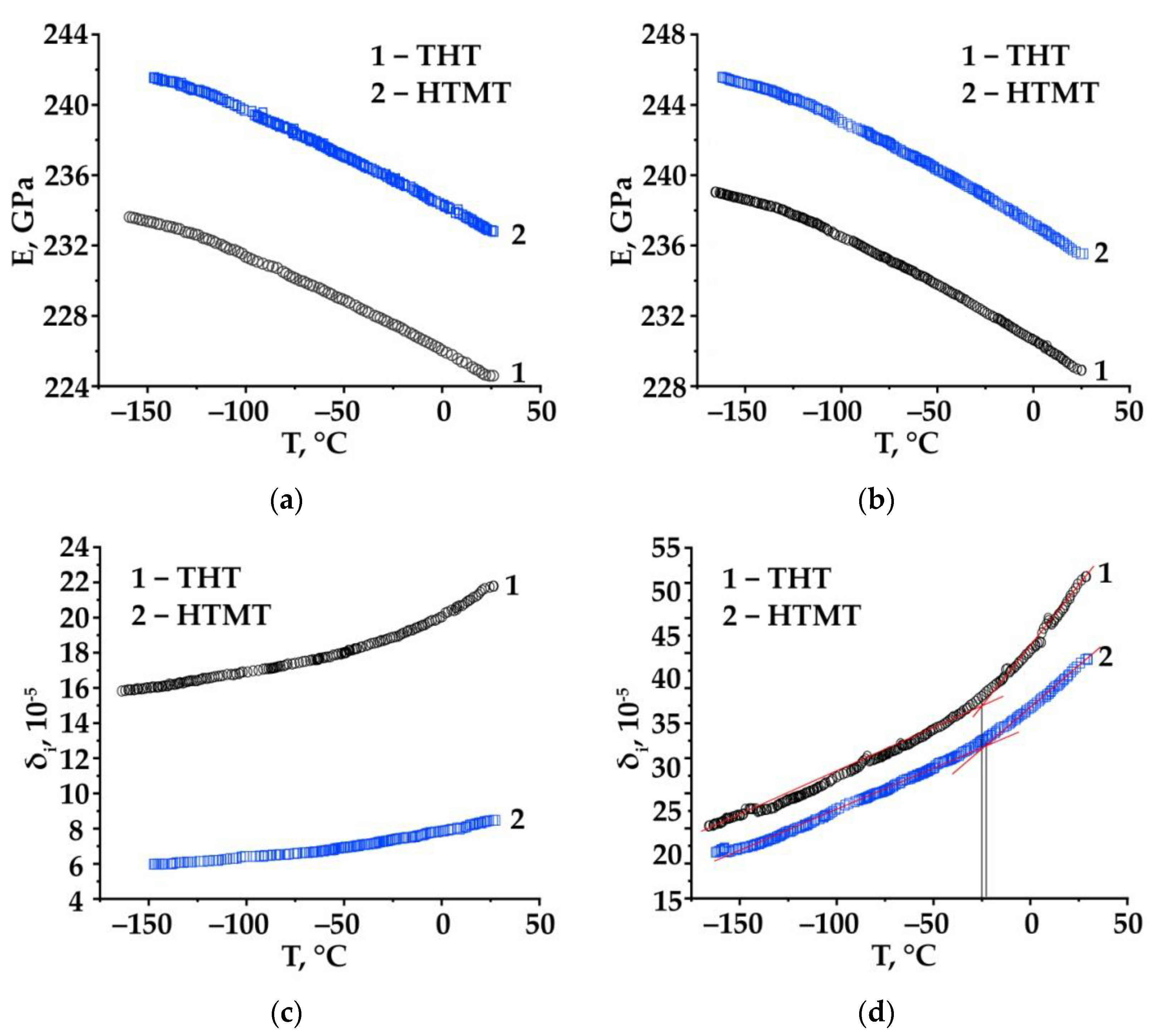
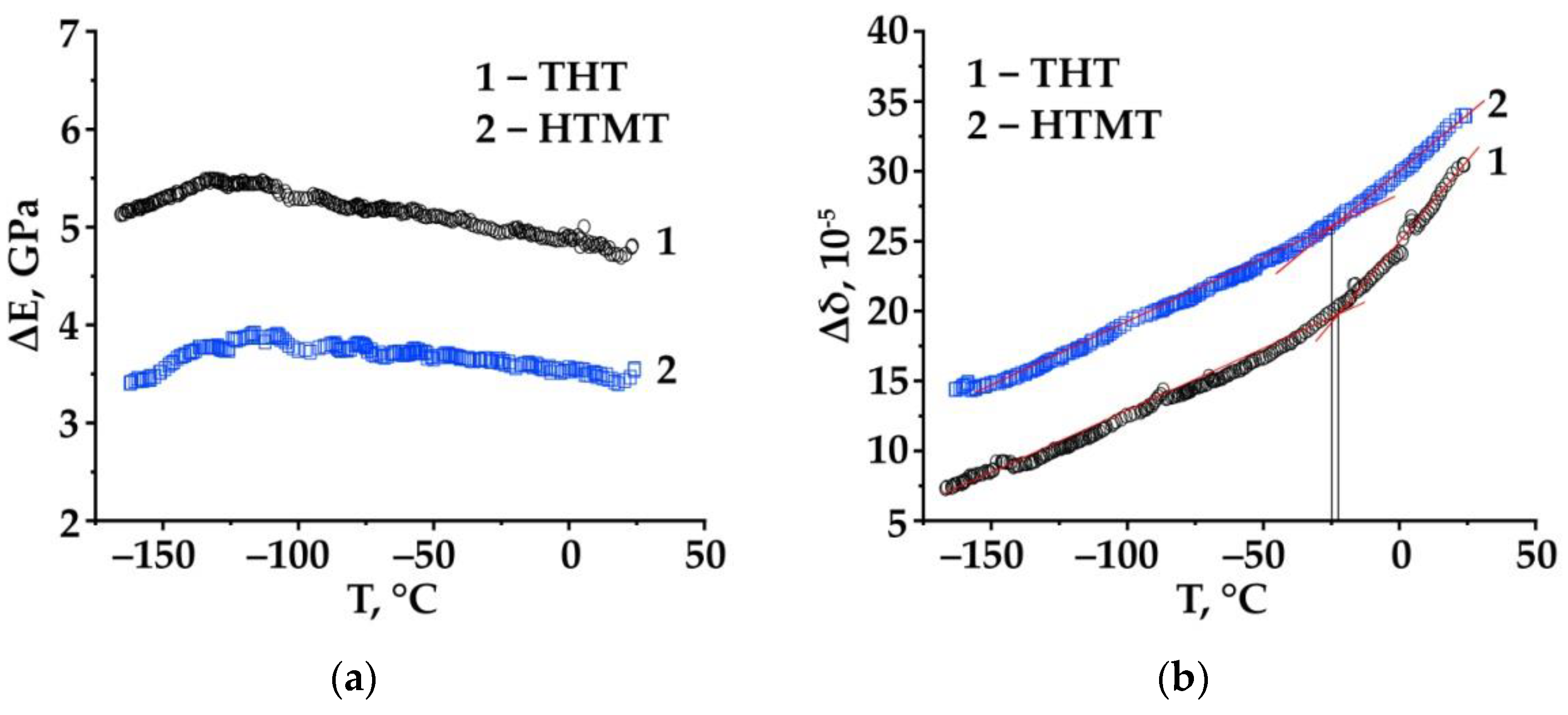
Figure 3 shows the temperature dependence (in the temperature range from room to cryogenic temperatures) of Young’s modulus (E) and the vibration decrement (δi) for the initial (after THT and HTMT) and bending-deformed EK-181 steel samples. Figure 4 shows the difference Δδ = δ2 − δ1 (where δ1 is the decrement in the initial state of the sample, δ2 is the decrement after its additional deformation) and the change in Young’s modulus ΔE = E2 − E1 (where E1 is Young’s modulus in the initial state of the sample, E2—Young’s modulus after deformation by three-point bending). The difference Δδ = δ2 − δ1 determines the level of the steel dislocation internal friction.
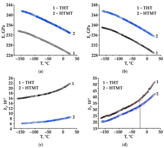
Figure 3.
Temperature dependence of Young’s modulus E (a,b) and the vibration decrement δi (c,d) for the initial (a,c) and bending-deformed (b,d) samples—EK-181 steel after different heat treatments (curve 1—THT, curve 2—HTMT).
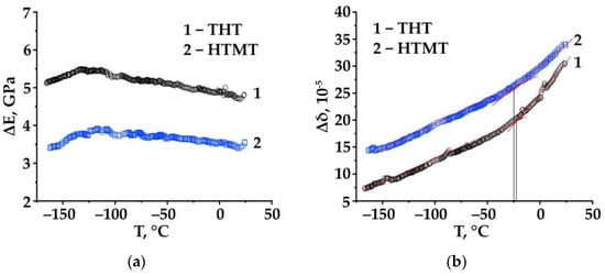
Figure 4.
Temperature dependence of the increments of Young’s modulus ΔE = E2 − E1 (a) and internal friction (the vibration decrement, ultrasonic frequency) Δδ = δ2 − δ1 (b) of EK-181 steel samples after different heat treatments (1—THT, 2—HTMT) in states up to (E1, δ1) and after (E2, δ2) plastic deformation by bending.
As can be seen from Figure 3c,d, plastic bending of the samples after both treatments leads to an increase in the value of the vibration decrement. Moreover, in the case of HTMT, the values of Δδ are higher compared with THT throughout the entire temperature range under study (Figure 4b).
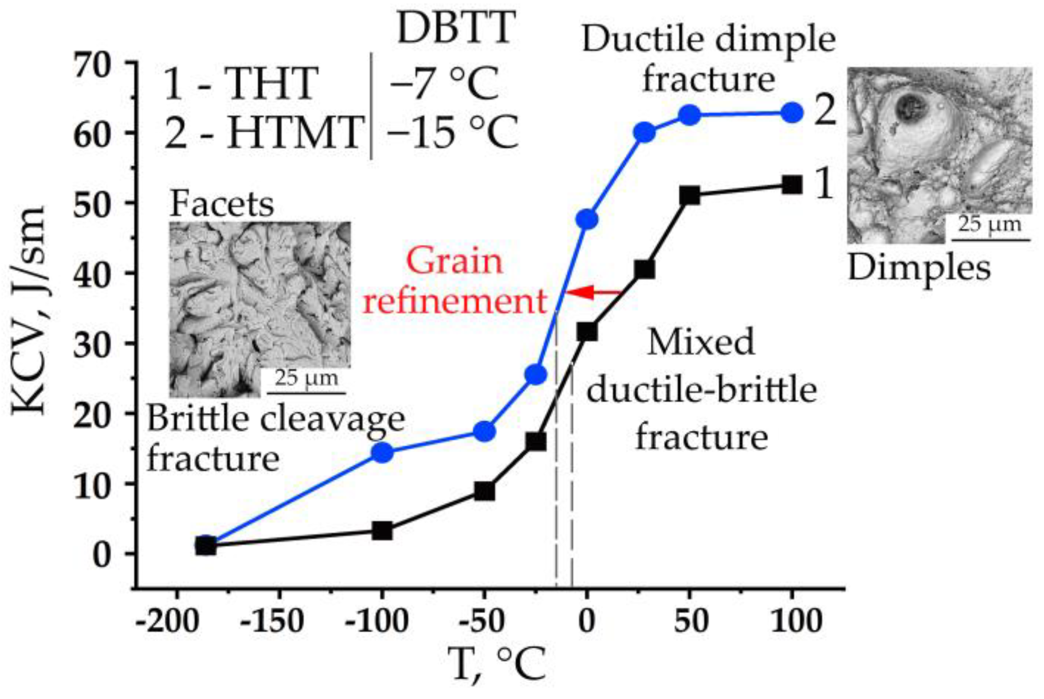
The temperature dependence of the decrement, measured at small amplitudes in the region of amplitude-independent internal friction, turns out to be almost similar to the temperature dependence of the EK-181 steel impact strength (KCV) (Figure 3c,d, Figure 4b and Figure 5). The vibration decrement of the steel samples decreases with the decreasing temperature (Figure 3c,d). At the same time, a break is observed in the temperature dependence curves δi(T) and Δδ(T) near the temperatures T ≈ −20 °C (after THT) and T ≈ −25 °C (in the case of HTMT) (Figure 3c,d and Figure 4b). Moreover, it is more distinct on the curves for bent samples. These temperatures are close to the ductile–brittle transition temperatures (DBTT) of the steel under study after THT and HTMT (≈−7 °C and ≈−15 °C, respectively), determined in [9] by the temperature dependence of its impact strength (Figure 5).
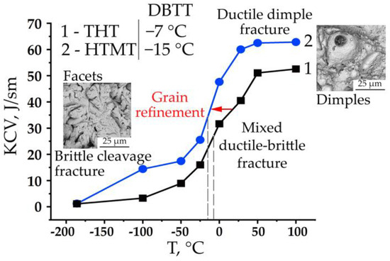
Figure 5.
Temperature dependence of the EK-181 steel impact toughness after THT and HTMT in the temperature range from 100 to −186 °C. DBTT—ductile–brittle transition temperature. Figure modified from [9].
The value of Young’s modulus in the states after THT and HTMT differs throughout the entire temperature range under consideration by approximately the same amount (Figure 3a) from those for an undeformed sample and a sample deformed by plastic bending (Figure 3b). For example, at room temperature testing of undeformed samples, HTMT leads to an increase in the elastic modulus of the steel, relative to TMT, by ≈ 8.5 GPa (from E1THT ≈ 224.5 to E1HTMT ≈ 233 GPa). Thus, the use of various thermal/thermomechanical treatment modes modifying the steel microstructure changes its elastic modulus.
Figure 3a,b also shows that for both steel states (THT and HTMT), the curves of the temperature dependence of Young’s modulus increase with the decreasing temperature. At the same time, after plastic bending, this trend persists, despite some numerical change in the value of E, compared to the undeformed samples. The introduction of fresh edge dislocations of the same sign into the microstructure of steel during plastic bending of the sample also leads to an increase in the modulus of elasticity in the temperature range under study, compared to the undeformed state (after THT and HTMT, Figure 3a,b and Figure 4a). Note that in the range of the steel ductile–brittle transition, no special features are observed on the E(T) curves (Figure 3a,b).
3.2. TEM and SEM Studies
In a fractographic study of the EK-181 steel samples after impact tests in the range from −186 to 100 °C in [9,10], it was established that on the upper shelf of the temperature dependence of impact strength, the steel fractures by the mechanism of ductile dimple transgranular fracture. On the lower shelf, the steel is destroyed by the transgranular quasi-cleavage mechanism, while in the range of ductile–brittle transition of the steel under study, the fracture mechanism changes from ductile to brittle (a mixed type of fracture is observed) (Figure 5).
To identify the influence of temperature on the regularities of the microstructure evolution of ferritic-martensitic steel EK-181 under impact loading, in this work, we investigated the features of its deformed microstructure near the central part of the fracture of impact samples destroyed at different temperatures (from −186 to 100 °C), in the states after THT and HTMT.
The microstructure and phase composition of EK-181 steel after THT and HTMT are qualitatively similar. It has a typical ferritic-martensitic tempered lath martensite structure. The main carbide phases are relatively coarse M23C6 carbides and nanosized MX carbonitrides. The second-phase particles differ in their compositions and sizes. The difference between the treatments mainly lies in the refinement of structural elements resulting from HTMT compared to THT. A detailed description of the structural features of the steel after these treatments is presented elsewhere [9].
When analyzing the electron microscopic images of the deformed steel microstructure in the temperature range from −186 to 100 °C, no noticeable influence of the treatment mode (THT and HTMT) was found. In this regard, in this work, the results of structural studies are presented using the example of the HTMT regime.
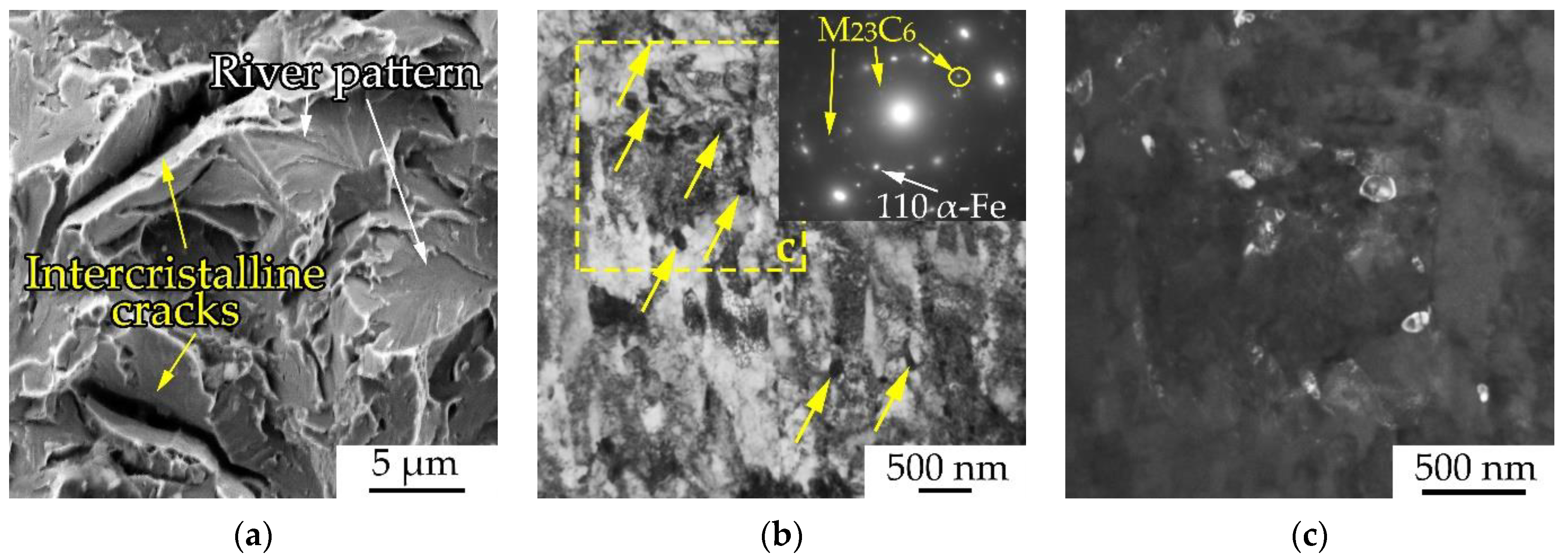
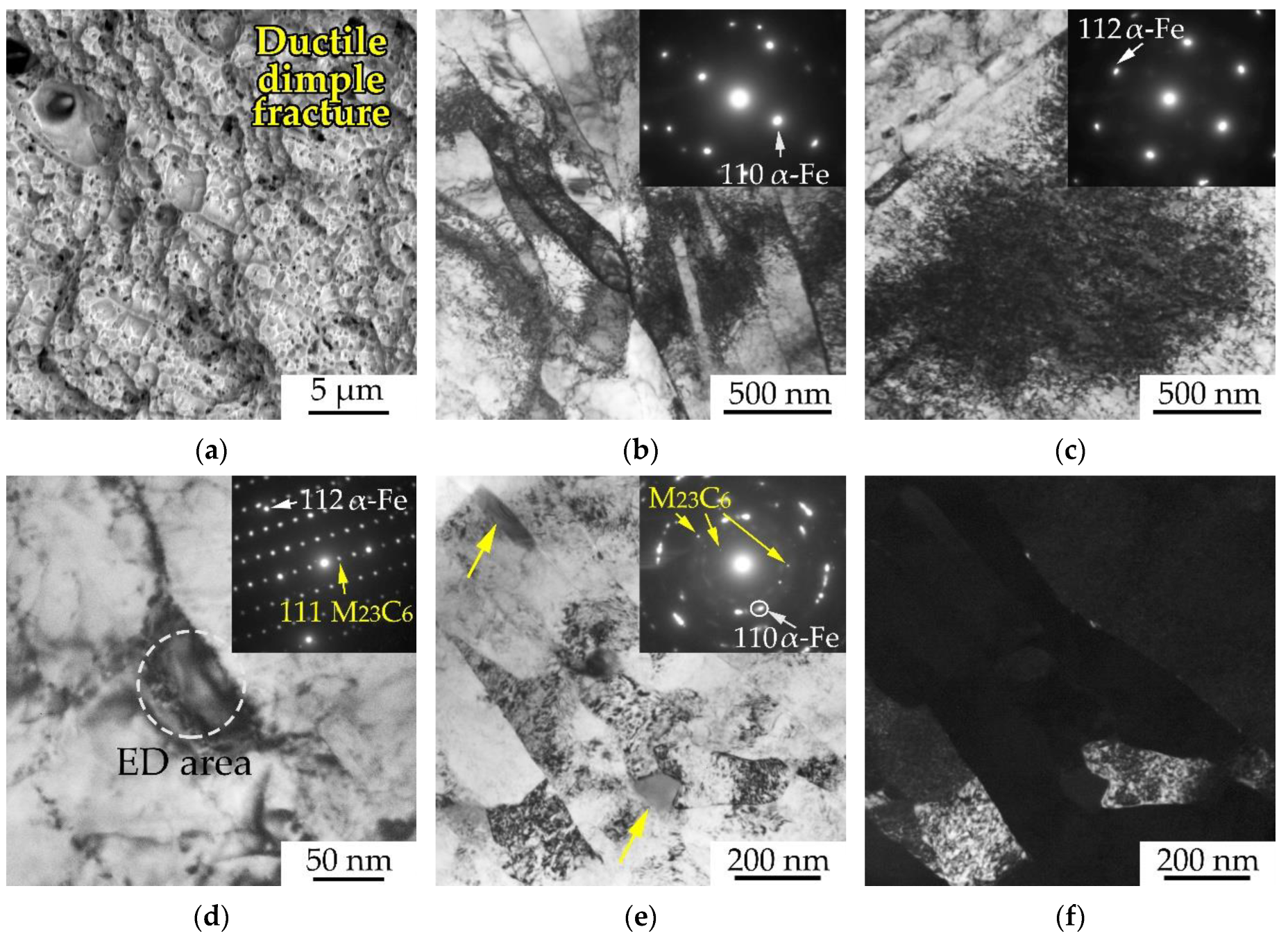
Figure 6 shows the electron microscopic images of the microstructure of EK-181 steel after HTMT in the fracture region of an impact sample destroyed at −186 °C (below the steel cold brittleness threshold, Figure 5). At this temperature, the fracture of the sample occurred predominantly by the mechanism of transgranular quasi-cleavage (with the formation of numerous quasi-cleavage facets and river pattern) with individual elements of intergranular fracture (Figure 6a). As can be seen from Figure 6b,d, in the state under consideration, the structure is mainly represented by the areas of lath martensite (with a lamella width of ≈100–200 nm) and ferrite grains (up to several microns in diameter). Let us note that the steel microstructure is quite heterogeneous (even within the same foil). Traces of plastic deformation are found locally. In some regions of the martensitic structure, an increased (up to ρ ≈ 5 × 1011 cm−2) dislocation density was detected compared to the initial state (where ρ varies from ~1010 to 1011 cm−2) (Figure 6b). In addition, partial fragmentation of martensitic lamellas is observed locally. Fragments (subgrains) are commonly of submicron sizes—the length of most of them does not exceed 500 nm (Figure 6e,f).
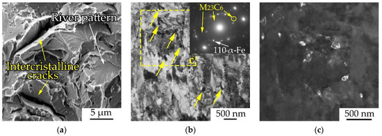
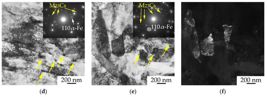
Figure 6.
SEM image of the central part of the fracture surface of an impact sample of EK-181 steel after HTMT, tested at −186 °C (a). TEM images of the deformed microstructure under the surface of its brittle fracture (yellow arrows indicate M23C6 carbides) (b–f): (b,d,e)—bright-field images; (c)—dark-field image in the reflection of M23C6 particles from the area limited by the rectangle in (b); (f)—dark-field image in the α-Fe reflection, corresponding to figure (e).
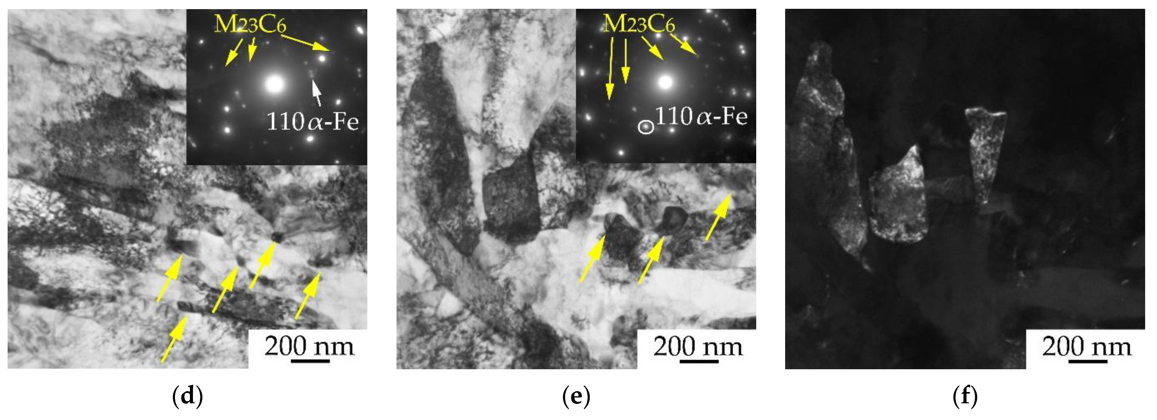
Figure 7 shows TEM images of the EK-181 steel microstructure after HTMT in the central region of the sample fracture at −25 and 0 °C (in the region of unstable crack propagation, where the fracture occurred according to the mechanism of transcrystalline quasi-cleavage), that is, in the region of its ductile–brittle transition temperature.
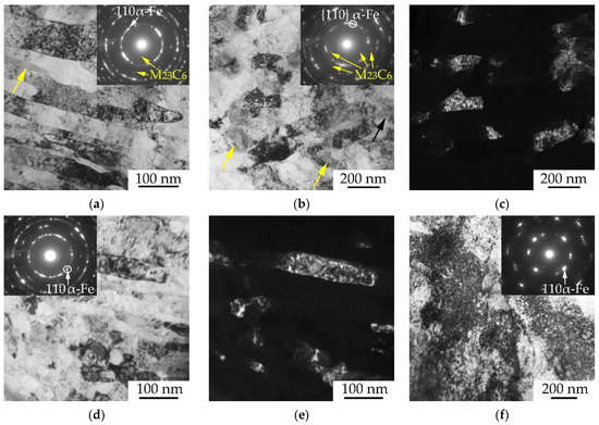
Figure 7.
TEM images of the deformed microstructure of EK-181 steel after HTMT near the fracture surface of the samples after impact tests at −25 (a–c) and 0 °C (d–f): (a,b,d,f)—bright-field images, (c,e)—dark-field images in reflections from α-Fe corresponding to (b,d). Yellow arrows indicate M23C6 carbides.
At these temperatures, using the methods of transmission electron microscopy, we revealed significant changes in the ferritic-martensitic structure of the steel compared to the initial state and that at other test temperatures. Among them, a significant fragmentation of the martensitic structure was observed. It consists, firstly, in the refinement (reducing the transverse dimensions) of martensitic lamellas. The lamellae width in this state is predominantly ≈50–100 nm (Figure 7a,d). Secondly, the martensite lamellas are transversely divided by low-angle misorientation boundaries (additional substructure). In this case, the fragment sizes are mainly 100–200 nm, as can be seen from the dark-field image in Figure 7c. Additional evidence of the formation of a highly fragmented and misoriented structure is the quasi-circular electron diffraction patterns (Figure 7a,b,d), characteristic of highly deformed states of steels, for example, after severe plastic deformation (up to a true degree of deformation e~4–6 [19,20]). In the states under consideration, an increased (up to ρ~1011–1012 cm−2) dislocation density in the martensite was also detected (Figure 7f).
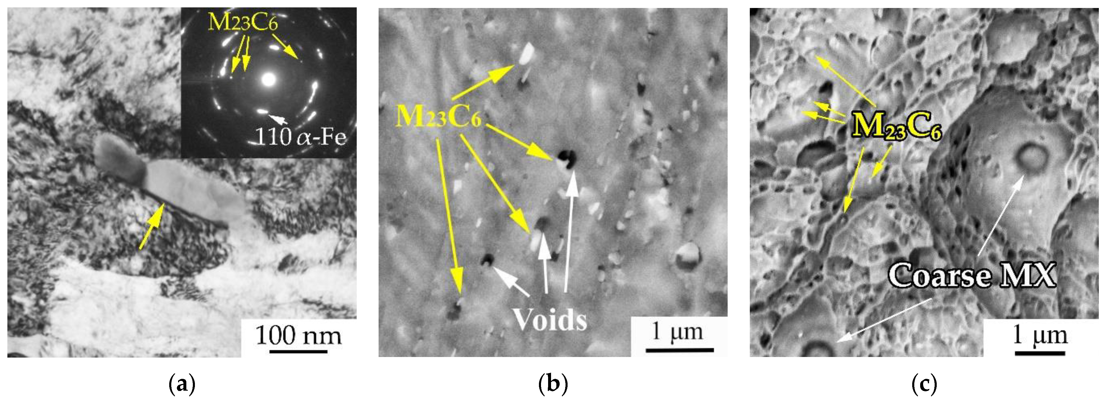
The deformed microstructure of the EK-181 steel impact samples in the HTMT state tested at the temperatures of 50–100 °C (at the upper shelf of impact toughness) is presented in Figure 8. At these temperatures, the initiation and propagation of the main crack occurs according to the mechanism of ductile dimple transgranular fracture; the fracture surface predominantly consists of ductile fracture dimples (Figure 8a).
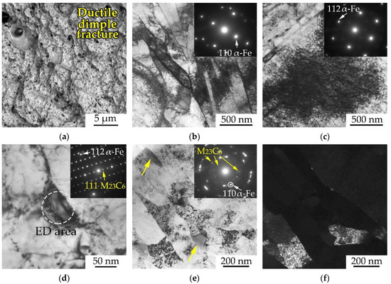
Figure 8.
SEM image of the central part of the fracture surface of an impact sample of steel EK-181 after HTMT, tested at 100 °C (a). TEM images of the deformed microstructure under the fracture surface (b–f): (b–e)—bright-field images, (f)—dark-field image in the reflection of α-Fe, corresponding to figure (e). ED area—electron diffraction area. Yellow arrows indicate M23C6 carbides.
The electron microscopic studies of the steel in the structural states under consideration revealed the areas practically unaffected by deformation (typical lamellar martensitic structure) and those with the traces of noticeably developed plastic flow processes (Figure 8). In the deformed areas, a fragmented martensitic structure is formed with the fragment sizes of ≈200–300 nm (Figure 8e,f).
It is important to note that at the discussed temperatures (50–100 °C), there is a significant increase in the dislocation density compared to the initial (before impact tests) state. This is most noticeable in the ferrite grains (the dislocation density in them can be comparable to that in the martensitic structure, that is, it reaches ρ~1011 cm−2), since in the undeformed states, their defectiveness was noticeably lower (ρ~1010 cm−2). At the same time, it is noteworthy that complex dislocation accumulations such as dislocation tangles are formed in ferrite regions (Figure 8c), not observed at other test temperatures. In our opinion, more intense changes in the microstructure could occur in grains (subgrains) favorably oriented towards the acting stresses during impact deformation of the steel samples. This is primarily observed in more plastic (compared to martensite laths) ferrite grains.
Other differences in the steel microstructure deformed at T = 50–100 °C, compared to lower temperatures of impact tests, include the presence of curvature and the migration of boundaries of martensitic lamellas (Figure 8b). The dislocation pileups are visible both near the LAB of some martensitic laths and inside them (Figure 8b). Apparently, such boundaries are sinks for dislocations during plastic deformation in the specified temperature range. An increase in the number of dislocations near obstacles (such as misorientation boundaries) contributes to the fragmentation of the steel martensitic structure.
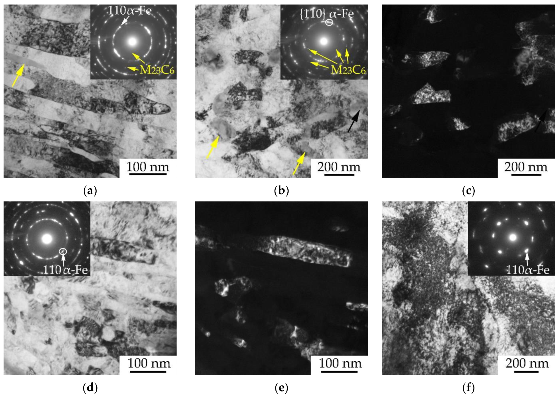
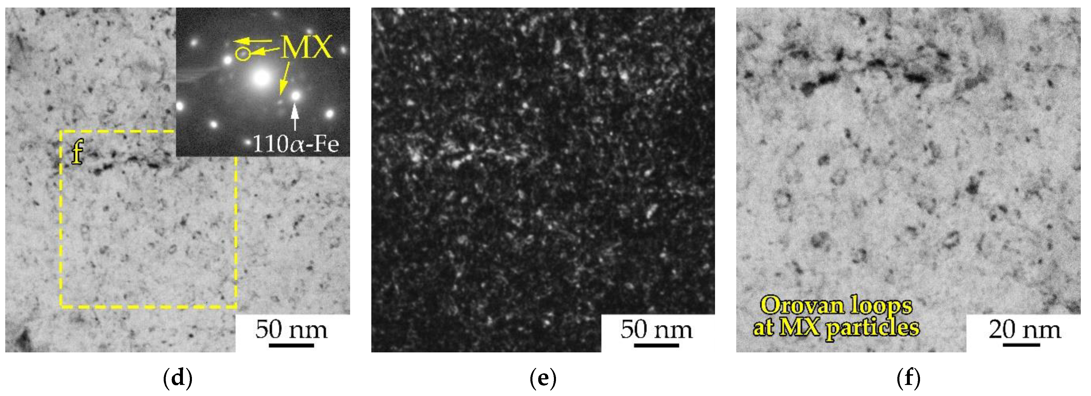
The studies of the influence of impact test temperature over the entire temperature range under consideration (from −186 to 100 °C—from the lower to the upper shelf of the temperature dependence of impact strength) on the carbide subsystem of steel near the fracture surface of the samples showed that the size and shape of the second-phase particles after deformation, relative to the initial state of the steel, do not undergo noticeable changes (Figure 6b–d, Figure 8d and Figure 9). From Figure 9a, it can be seen that M23C6 carbides predominantly have elongated shapes (their length reaches ≈300 nm, their width mainly ranges from ≈30 to 100 nm). Such particles are located mainly at high- and low-angle boundaries (the boundaries of prior austenite grains, packets, blocks and martensite lamellas, Figure 6b–d, Figure 8d and Figure 9). In addition, more equiaxed precipitates of this phase are found inside the matrix grains. Dislocation pileups were found near the M23C6 particles (Figure 8d and Figure 9a), indicating that such particles might be insurmountable obstacles for the moving dislocations. During plastic deformation, M23C6 particles apparently create a stress field around themselves, distorting the crystal lattice of the matrix and leading to the appearance of azimuthal misorientations in the electron diffraction patterns (Figure 9a).
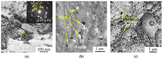
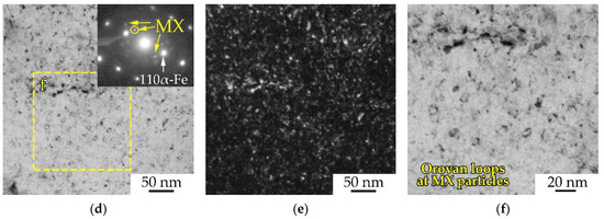
Figure 9.
Electron microscopic images of the microstructure of impact samples of EK-181 steel after HTMT, destroyed at 0 °C (a,d–f) and −25 °C (b,c): (a)—bright-field TEM image of the dislocation structure near an M23C6 carbide particle in a deformed microstructure steel sample below the fracture surface; (b,c)—SEM images of the side surface of the sample near the fracture surface, and of the fracture surface, respectively; (d)—bright-field TEM image of the result of the interaction of dislocations with nano-sized particles of the MX phase after the destruction of the impact sample; (e)—corresponding dark-field image in the MX reflection; (f)—enlarged area highlighted by a rectangle in (d).
An SEM study of the side surface of impact samples after testing in the temperature range of the ductile–brittle transition near the fracture surface revealed the formation of micropores on the particles of M23C6 carbides (Figure 9b). In the fractographic studies of ductile fracture areas, these particles are often found at the bottom of ductile fracture dimples (Figure 9c). In the areas of brittle fracture, some large (up to several microns in size) particles of M23C6 carbides and MX carbonitrides are destroyed under the action of applied stress during impact loading due to the incompatibility of plastic deformation of the matrix and inclusions. The accumulation of gliding dislocations in front of strong carbide particles at the front of a propagating main crack leads to the formation of discontinuities (pores or microcracks) near them (Figure 9b), promoting the relaxation of elastic stresses arising during loading. When the bridges between the pores are destroyed, ductile dimple facture occurs (Figure 9c). In addition, the M23C6 particles themselves might become the initiators of brittle transgranular fracture.
Fine particles of cubic vanadium carbonitride of the MX type in the deformed microstructure, similarly to that in the initial state (after THT and HTMT) have sizes up to 10–15 nm (Figure 9d–f). Their density is quite high, and they are uniformly distributed inside the matrix grains. As can be seen from Figure 9d–f, dislocation loops are formed on the MX particles during deformation (during impact tests), which indicates that the particles under discussion can be overcome by gliding dislocations according to such mechanism as the Orowan mechanism at the temperatures of −25 and 0 °C.
The heterogeneity of the formed steel microstructure observed by TEM at different test temperatures may also be due to several factors. The dimensions of the plastic zone that forms before the front of the propagating main crack for the type of impact samples under study (small samples with a V-notch) are apparently small, especially at low (negative) test temperatures. Accordingly, the degree of deformation can change (decrease) significantly when we move away from the fracture surface of impact samples even a few microns. In addition, the area of various fracture zones (zones of crack initiation, crack propagation, etc.) changes significantly with the temperature.
3.3. SEM EBSD Analysis
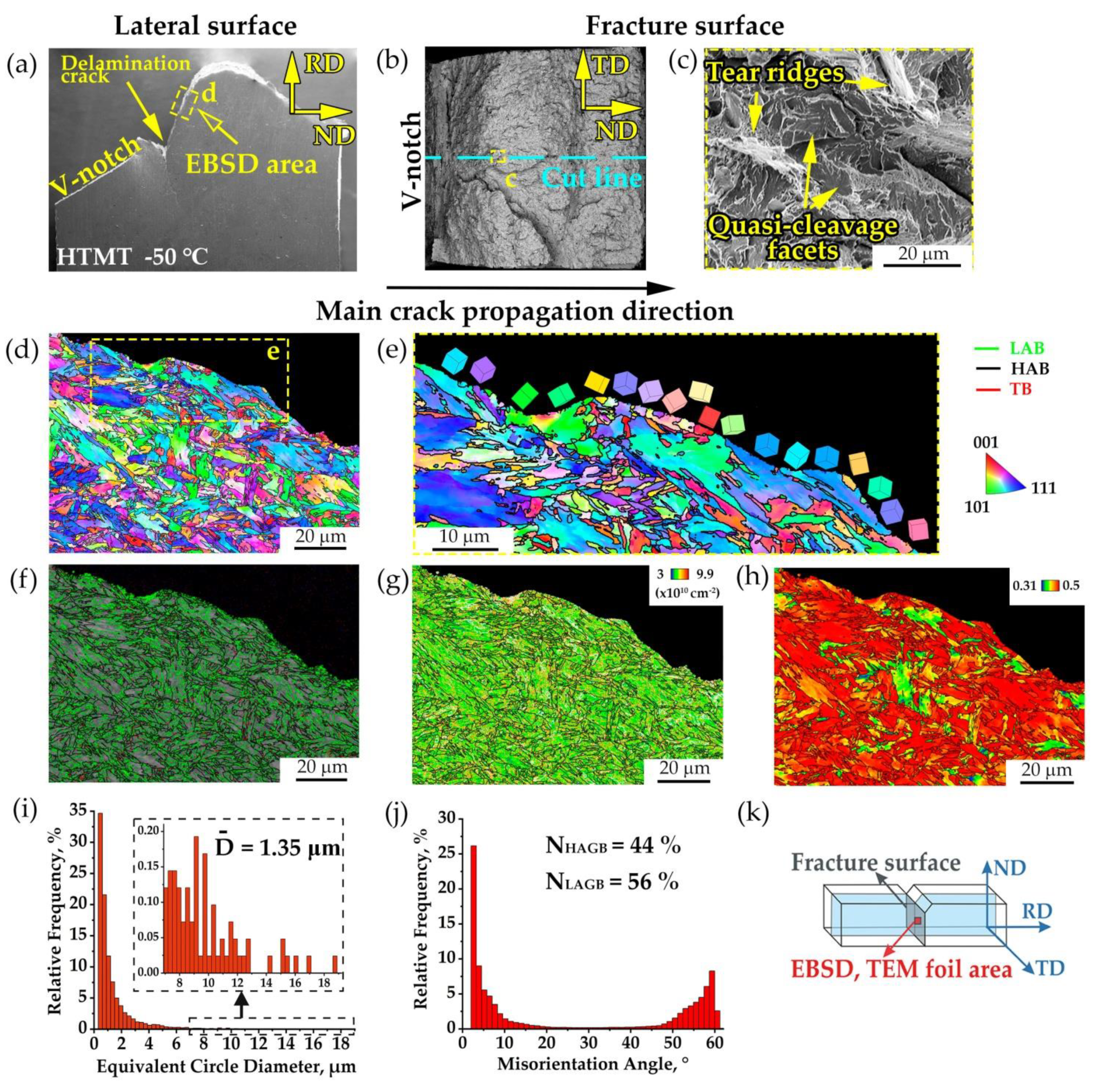
Figure 10 shows SEM EBSD images of the deformed microstructure near the fracture surface of the EK-181 steel sample after HTMT, fractured at −50 °C. The area under study is marked in Figure 2b and Figure 10k. Note that at this temperature, as shown in [9], hot-rolled steel samples are characterized by the formation of delamination microcracks perpendicular to the main crack propagation direction. Such microcracks are an additional factor in increasing the impact toughness of the steel after HTMT, compared to THT, where they are not formed [9].
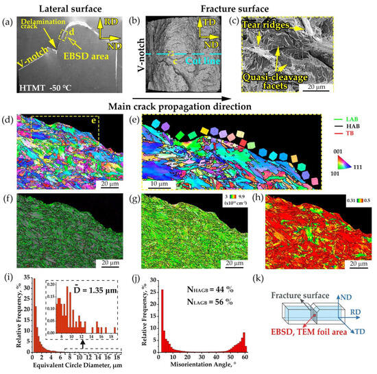
Figure 10.
SEM images of the microstructure of the impact sample of steel EK-181 after HTMT, fractured at −50 °C: (a)—side surface of the sample; (b)—fracture surface; (c)—enlarged fractographic image in the area of unstable crack propagation; (d,e)—EBSD orientation maps with HAB; (f)—EBSD band contrast map with LAB, HAB and TB (twin boundaries); (g)—EBSD Geometrically Necessary Dislocations map; (h)—EBSD Schmid factor map with HAB; (i)—histogram of grain size (ECD) distribution; (j)—histogram of grain misorientation distribution, and (k)—scheme of a Charpy-type sample.
For the EBSD study, we selected the area under the zone of unstable crack propagation (Figure 10a,b). The fracture in this area occurred by the mechanism of a transcrystalline quasi-cleavage (Figure 10c). It is important to pay attention to the fact that we are considering the result of the sample fracture. In this regard, the observed changes in the microstructure are a consequence of the plastic deformation processes preceding fracture.
The cleavage planes on the sample brittle fracture surface (Figure 10c) represent facets of transcrystalline quasi-cleavage along the {100} type planes [16,21,22]. A brittle main crack, propagating from facet to facet, may deviate due to different orientations of the cleavage planes in various structural elements of the steel (grains) in relation to the acting load. The main crack deflects when it encounters some high-angle boundaries, which represent the boundaries of blocks, martensite packets and prior austenite grains (Figure 10d–f). At the same time, it overcomes low-angle boundaries almost unhindered (Figure 10f). According to Figure 10e, the longest flat areas on the fracture profile pass through the body of the largest grains (≈10–20 µm in size). Note that between the quasi-cleavage facets, there are tear ridges with elements of ductile dimple fracture (Figure 10c). Probably the tear ridges in Figure 10d–h correspond to areas with relatively small (up to several microns in size) grains.
Similar results are reported in [23,24,25,26,27,28]. The authors of many works [23,28,29,30,31] come to a conclusion that microstructural refinement of steels (with an increase in the length of high-angle boundaries as obstacles to the propagation of quasi-cleavage cracks) reduces their DBTT very effectively.
A statistical analysis of the results of the EBSD study of the steel microstructure below the fracture surface is presented in Figure 10i,j. According to the data obtained, it has a predominantly fine-grained structure. The average grain sizes in this state are ≈1.35 µm (Figure 10i). As shown in [9], the grain sizes of steel in the initial state (after HTMT, in the cross section (TD-RD)) are 2.1 μm. Thus, impact tests at T = −50 °C lead to an approximately one-and-a-half-fold decrease in grain sizes near the steel fracture surface in the zone of unstable crack propagation, compared to the undeformed state.
Figure 10j shows that the distribution of grains and subgrains by misorientation angles is bimodal, which is typical for steels with a lath martensite structure [32]. In many grains, a significant number of LAB are observed (Figure 10f). The fraction of LAB in the structural state under study is ≈56%, and the fraction of HAB is ≈44% (Figure 10). The presence of misorientations inside the grains, caused by an increased dislocation density, can also be seen on the Geometrically Necessary Dislocations (GND) map (Figure 10g).
Figure 10h shows a map of the Schmid factor distribution for the main gliding systems ({110}[111], {211}[111] and {321}[111]) of EK-181 steel, the matrix phase of which is BCC martensite. It can be seen from this figure that the Schmid factor has the values close to the maximum (0.5) value in most steel grains. This means that during the process of plastic deformation, intense dislocation gliding can occur in them. However, there are grains in which the Schmid factor is ≈0.3 (Figure 10h), that is, the grains unfavorably oriented with respect to the acting stresses.
4. Discussion
When studying the internal friction of EK-181 steel samples using a non-destructive acoustic method in the states with different levels of strength and plastic properties (after THT and HTMT) in the temperature range from −196 to 25 °C, it was established that the temperature dependence of the vibration decrement is similar to the temperature dependence of the steel impact toughness. A characteristic break is observed on the curves of the temperature dependence of the vibration decrement in the vicinity of the temperature T ≈ −20 °C (after THT) and T ≈ −25 °C (after HTMT). These temperatures are close to those of the ductile–brittle transition of the steel under study, determined during the Charpy impact tests. Note that in both experiments (impact toughness tests and acoustic measurements of amplitude-independent absorption with high frequency (100 kHz) forced vibrations), the dislocation velocities are close to each other [33].
Similar results were obtained in [33] using the example of the V–4Ti–4Cr alloy (with a BCC lattice) and the ferritic-martensitic steel EK-181 studied in this work (in states after traditional and combined heat treatment). The authors of [33] demonstrated the presence of a correlation in the changes in impact toughness and internal friction (amplitude-independent decrement) when cooling the samples from room temperature to the boiling temperature of liquid nitrogen.
According to [33], the break in the δi(T) curve at the temperatures close to that of the ductile–brittle transition is caused by a sharp change in the ductile (most likely electronic) drag of dislocations. Another factor influencing the DBTT position is the development of residual internal stresses in the material [33].
Thus, at the temperatures below DBTT, a low level of dislocation internal friction is observed in EK-181 steel (low ductile dynamic drag of dislocations) [3].
In addition, in this work, it has been established that a characteristic feature of the EK-181 steel after both treatments (THT and HTMT) is a sharp increase in the elastic modulus with a decrease in the temperature from room temperature to −196 °C. At the same time, in the range of the ductile–brittle transition, no special features were found on the E(T) curves. At the same time, HTMT led to an increase, compared to THT, in the Young’s modulus of this steel over the entire considered range of temperature from −196 to 25 °C.
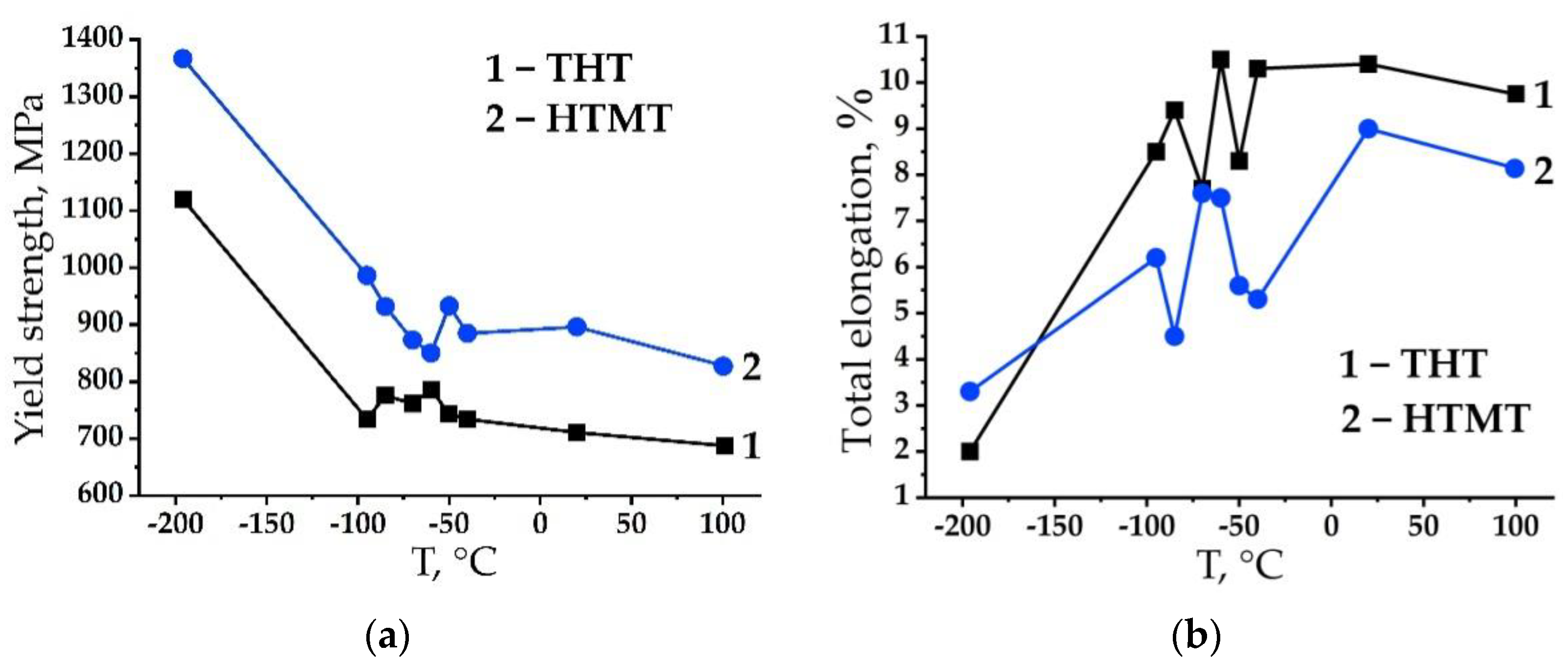
The results on the study of the temperature dependence of Young’s modulus are consistent with those of the study of the temperature dependence of the strength properties of EK-181 steel after THT and HTMT (during uniaxial tensile tests in the temperature range from −196 to 100 °C) [9,10,12]. It is shown in [9] that as the temperature drops below 20 °C, the yield strength of this steel increases after both treatments (Figure 11a). In this case, as can be seen from Figure 11b, a considerable decrease in the elongation to failure with the decreasing temperature occurs only at −196 °C.
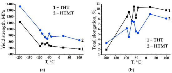
Figure 11.
Curves of temperature dependence of EK-181 steel mechanical properties after THT and HTMT in the temperature range from 100 to −196 °C: yield strength (a), total elongation to failure (b) [9].
Note that the ductile–brittle transition temperature is not a material constant [3,16,34]. Its significance is determined by many factors. They include the conditions (method and speed of the external load application, stress state diagram) of the tests, the types (shape, dimensions, presence of a notch, surface condition, etc.) of the samples, as well as the structural state of the material.
In accordance with the results obtained, the effect of cold brittleness is most clearly manifested in dynamic tests on impact toughness of notched samples, which have a higher loading rigidity, compared to static tensile tests. According to tensile tests, the temperature of the ductile–brittle transition can apparently be defined as that of a sharp change in the slope of the curve of the temperature dependence of the yield strength near T = −80 °C, in the region of which there is a noticeable scatter in the values of the total elongation to failure (Figure 11b).
In electron microscopic studies of the microstructure near the fracture of impact samples of EK-181 steel, destroyed in the range from −186 to 100 °C, traces of plastic deformation were found at all temperatures, including those in the range of ductile–brittle transition and those corresponding to the lower shelf of the curve of the impact toughness versus the temperature. The main signs of the presence of plastic deformation near the sides of the main crack are as follows:
- -
- increase in dislocation density with the formation of complex dislocation pileups as a result of their interaction with each other, with particles of the second phases (with nano-sized particles of the MX phase and with M23C6 carbides), as well as with other obstacles such as grain boundaries and subgrains;
- -
- curvature and migration of martensite laths boundaries;
- -
- refinement of the grain–subgrain structure;
- -
- fragmentation of martensitic laths with the formation of new low-angle boundaries.
At the same time, the intensity of each of these processes depends on the temperature (it decreases with the decreasing temperature) of impact tests.
In our opinion, the observed differences in the microstructure formed near the fracture surface are due to that in the dislocation mobility depending on the impact test temperature (with the decreasing temperature, the Peierls–Nabarro braking force and the efficiency of blocking of gliding dislocations by impurity atoms increase). This conclusion is also supported by the results of internal friction tests. In addition, the regularities of plastic deformation can be determined by the dislocation slip crystallography in a BCC lattice (the presence of a large number of slip systems, with a possible decrease in the number of active slip systems with the decreasing deformation temperature) [34].
In [4], using the example of the EK-164 austenitic reactor steel, it is shown that internal friction in FCC alloys is significantly higher (≈10 times) than in BCC materials (EK-181 steel, vanadium alloys). The high ductility of the movement of dislocations in an FCC metal, which requires a large quantity of work to maintain their motion (plastic deformation), ensures the elastic stress relaxation at the crack front. Under such conditions, the state of cold brittleness with the possibility of crack opening in FCC metals is not realized [3].
As shown above, a characteristic feature of EK-181 steel as a cold-brittle material is a sharp increase in Young’s modulus and yield strength with the decreasing temperature. The presence of a strong temperature dependence of the yield strength at negative temperatures is a distinctive property of BCC metals compared to FCC materials [22,35,36]. It is believed [22,37,38] that this is due to the pronounced influence of temperature-dependent Peierls–Nabarro forces, the types of dislocations and their inhibition by interstitial impurity atoms at low temperatures in BCC metals.
The interstitial impurity atoms located in octahedral and tetrahedral pores in BCC metals cause asymmetrical distortions of the crystal lattice. Due to the presence of such distortions, dissolved atoms actively interact with dislocations (including screw ones) in BCC metals, forming atmospheres on the dislocations (such as Cottrell atmospheres). In close-packed FCC and hexagonal close-packed (HCP) lattices, the interstitial impurities hardly interact with screw dislocations and do not block them. As a result, an effective blocking of dislocations in BCC metals by interstitial impurities is possible [22].
In addition, since BCC metals have a larger number of slip systems than FCC materials, this facilitates the transition of dislocations from one slip plane to another. At room and elevated temperatures, gliding in them can be carried out in the {110}<111>, {112}<111> and {123}<111> systems [39]. Due to the high stacking fault energy (SFE), the splitting of dislocations in BCC steels is difficult. Together with a large number of slip systems, this contributes to the easy transverse gliding of screw dislocations and the formation of various kinds of dislocation pileups and dislocation cellular or fragmented structures [35,36,40]. The formation of such microstructures was found in this work at temperatures in the vicinity of and above DBTT. When BCC materials are cooled, there is a sharp decrease in the dynamic braking of dislocations and an increase in their dynamic mobility. At the temperatures close to −186 °C, only traces of plastic deformation are observed near the main crack sides.
A significant number of works currently focus on the issue of cold brittleness of steels with a BCC lattice. In addition to carrying out mechanical tests to identify the influence of various factors on the position of the ductile–brittle transition interval of steels, in recent years, with the development and fairly widespread dissemination of the methods for preparing samples using the FIB method in local areas of the material and high-resolution methods of structural studies (TEM and SEM EBSD analysis), the attention of many researchers is aimed at identifying the features of destruction and changes in the microstructure of the steels with a BCC lattice as a result of various types of deformation, including impact loading.
In the works [41,42,43,44], the influence of impact test temperature both on the microhardness distribution along the main crack propagation path and the width of the plastic deformation region of the steel with a ferritic-martensitic microstructure was studied in detail. It has been shown [41,42,43] that the plastic zone is formed not only in the upper and central part of the temperature curve of the impact strength, but also on the lower shelf. It is evidenced by the change (increase) in the steel microhardness near the sides of the main crack, compared to the initial undeformed state. However, as noted by the authors of [41,42,43], the width of the plastically deformed region significantly decreases with the decreasing temperature.
The authors of [45] claim that in the course of quasi-cleavage of lath martensitic steel brittle fracture predominated. In some areas, a significant plasticity was observed, as evidenced by the presence of a plastic zone near the tear ridges and a high density of dislocations in the areas under the quasi-cleavage facets.
In [46], using EBSD methods, it was established that under the conditions of fracture of a ferritic steel in the cold-brittleness range, ductile microcracks appear along with the cleavage microcracks. This work [46] shows that the microstructure of the plastic zones under the brittle and ductile components of the fracture formed by the main crack is significantly different.
According to the Ioffe diagram [22,23], the yield strength of the BCC materials in the range of ductile fracture is higher than the critical stress of brittle fracture (peel resistance), which is practically independent of temperature. Consequently, such failure is always preceded by a significant plastic deformation, as we found in this work for EK-181 steel.
In contrast to brittle fracture, ductile fracture is characterized by a continuous nucleation of multiple sources in the field of plastic deformation, which moves along with the growing macrocrack [46,47]. In our opinion, particles of the second phases play an important role in the implementation of the mechanism of ductile dimple fracture of EK-181 steel. The M23C carbides are the obstacles insurmountable by the dislocations moving during plastic deformation. According to TEM studies, they create a stress field around themselves, distorting the crystal lattice of the matrix and leading to the appearance of azimuthal misorientations in the electron diffraction patterns. The reason for this behavior is probably due to the elastoplastic incompatibility between the tempered martensitic structure (having a BCC lattice) and the harder Cr23C6 precipitates (having an FCC structure). An accumulation of defects near the carbides during deformation leads to the formation of voids (pores) and/or microcracks. At the same time, the discontinuities, in accordance with the results of fractographic studies of EK-181 steel, can form both at the particle–matrix boundary and during the particle destruction. An interesting fact was observed in [40] that one of the reasons for the destruction of M23C6 particles is the formation of deformation twins inside them during plastic deformation of the sample.
In the case of brittle fracture of the steel samples by quasi-cleavage, in accordance with the Ioffe theory [34,48], on the contrary, the critical stress of its brittle fracture is reached earlier than the yield strength. However, the Ioffe scheme does not take into account the local stress concentration at the tip of a moving crack [34]. If the stresses here significantly exceed the yield strength, then the crack development will be associated with the plastic deformation, and the work of this deformation may turn out to be so large that, in accordance with the Griffith criterion, the crack can no longer propagate as a brittle one [34]. It is believed that brittle fracture initiates from a single source and propagates continuously from facet to facet [46]. However, according to [46], for the applied stress to achieve the value of peel resistance even in the absence of general plastic deformation, a small amount of local plastic deformation is required. In the region of brittle fracture, a plastic zone can also form before the front of a propagating main crack [46]; therefore, prior to the sample failure, there is certain plastic deformation of the material near the main crack sides.
The SEM EBSD and TEM studies carried out in this work confirmed the presence of traces of plastic deformation under the surface of brittle fracture by transgranular quasi-cleavage. The EK-181 steel has a fairly developed grain–subgrain structure. If, under impact loading, the cleavage occurs along the {100} planes, then, for a brittle main crack to propagate, it is necessary to destroy the bridges between the quasi-cleavage facets in adjacent grains. As follows from the fractographic studies, this contributes to the appearance of tear ridges—that is, the areas of ductile fracture with the finest grains on the fracture profile (lateral surface).
Similar results were obtained in [49]. In a study of the deformation characteristics of the cleavage crack propagation in a 09G2S low-alloy low-carbon steel with a ferrite-pearlite microstructure, it was shown [49] that the deformation accompanying the cleavage crack growth was formed when the joints between cracks propagating in parallel planes were broken. The crack grows within one plane without detectable deformation, and the joints rupture by a ductile mechanism (according to the scheme of mixed loading by separation and shear). As noted by the authors of [49], the degree of overlap of cleavage cracks determines the relationship between the shear mode and the detachment mode during a joint deformation, which controls the shape and depth of plastic deformation zones.
5. Conclusions
The behavior of the EK-181 low-activation ferritic-martensitic reactor steel in the states with different levels of strength and plastic properties in the temperature range of its low-temperature embrittlement was studied using the non-destructive acoustic method of internal friction and the methods of transmission and scanning electron microscopy. The main regularities revealed in this study are as follows:
- The curves of the temperature dependence of the vibration decrement of EK-181 steel after THT and HTMT in the range from −196 to 25 °C are similar to those of its impact toughness. A characteristic break was found on these curves in the region of the ductile–brittle transition temperature.
- At the temperatures below DBTT, the level of dislocation internal friction (the vibration decrement) in EK-181 is significantly lower compared to its values at room temperature.
- It was found that HTMT increases the steel Young’s modulus in the temperature range from −196 to 25 °C, compared to that after THT. This is due to the modification of their microstructure.
- When the temperature decreases from room temperature to −196 °C, the steel elastic modulus increases without any features in the ductile–brittle transition temperature range.
- Changing the temperature of impact tests from 100 to −196 °C (from the upper to the lower shelf of the temperature dependence of impact toughness) has a significant impact on the microstructure of EK-181 steel near the fracture surface of Charpy-type samples, compared to the initial state.
- Throughout the entire experimental temperature range, both under the surface of ductile dimple transcrystalline fracture and brittle fracture by quasi-cleavage, the traces of plastic deformation were found: increase in dislocation density, fragmentation of martensitic lamellas, and formation of complex dislocation pileups. These processes become less intensive as the temperature is decreased, which is due to the weaker dislocation mobility.
Author Contributions
Conceptualization, N.P. and I.L.; Formal analysis, V.O., B.K. and N.D.; Investigation, N.P., K.S., S.A., B.K., N.D. and K.M.; Methodology, N.P.; Project administration, N.P.; Supervision, V.C., M.L.-S. and B.K.; Visualization, V.O., K.S., S.A. and K.M.; Writing—original draft, N.P.; Writing—review and editing, I.L., V.C. and M.L.-S. All authors have read and agreed to the published version of the manuscript.
Funding
This study was performed according to the Government research assignment for the Institute of Strength Physics and Materials Science of the Siberian Branch of the Russian Academy of Sciences (ISPMS SB RAS), project No. FWRW-2021-0008.
Data Availability Statement
All the data supporting the results were provided within the article.
Acknowledgments
The research was carried out using the equipment of the Share Use Centre “Nanotech” of the ISPMS SB RAS.
Conflicts of Interest
The authors declare no conflict of interest.
References
- Odette, G.R.; Zinkle, S.J. Structural Alloys for Nuclear Energy Applications; Elsevier: Amsterdam, The Netherlands, 2019; p. 655. [Google Scholar] [CrossRef]
- Klueh, R.L.; Nelson, A.T. Ferritic/martensitic steels for next-generation reactors. J. Nucl. Mater. 2007, 371, 37–52. [Google Scholar] [CrossRef]
- Chernov, V.M. Cold brittleness of metals as a structural multistage dislocation process. Phys. Solid State 2023, 5, 693–702. [Google Scholar] [CrossRef]
- Stornelli, G.; Schino, A.D.; Mancini, S.; Montanari, R.; Testani, C.; Varone, A. Grain Refinement and Improved Mechanical Properties of EUROFER97 by Thermo-Mechanical Treatments. Appl. Sci. 2021, 11, 10598. [Google Scholar] [CrossRef]
- Abe, F.; Kern, T.-U.; Viswanathan, R. Creep-Resistant Steels; Woodhead: Cambridge, UK, 2008; p. 700. [Google Scholar]
- Srinivasan, S.; Basu, J.; Moitra, A.; Sasikala, G.; Singh, V. Effect of thermal aging on ductile–brittle transition temperature of modified 9Cr–1Mo steel evaluated with reference temperature approach under dynamic loading condition. Metall. Mater. Trans. A 2013, 44, 2141–2155. [Google Scholar] [CrossRef]
- Sasikala, G.; Ray, S.K. Evaluation of quasistatic fracture toughness of a modified 9Cr–1Mo (P91) steel. Mater. Sci. Eng. A 2008, 479, 105–111. [Google Scholar] [CrossRef]
- Polekhina, N.A.; Litovchenko, I.Y.; Almaeva, K.V. Microstructure, Structural-Phase Transformations, and Mechanical Properties of Low-Activation 12% Chromium Ferritic-Martensitic Steel EK-181 Depending on the Treatment Conditions. Inorg. Mater. Appl. Res. 2022, 13, 1247–1260. [Google Scholar] [CrossRef]
- Polekhina, N.; Linnik, V.; Litovchenko, I.; Almaeva, K.; Moskvichev, E.; Chernov, V.; Leontieva-Smirnova, M.; Degtyarev, N.; Moroz, K. The Microstructure, Tensile and Impact Properties of Low-Activation Ferritic-Martensitic Steel EK-181 after High-Temperature Thermomechanical Treatment. Metals 2022, 12, 1928. [Google Scholar] [CrossRef]
- Polekhina, N.A.; Linnik, V.V.; Litovchenko, I.Y.; Almaeva, K.V.; Chernov, V.M.; Leontieva-Smirnova, M.V. Fracture features of impact samples of low-activation ferritic-martensitic steel EK-181 after high-temperature thermomechanical treatment. Lett. Mater. 2022, 4, 451–456. [Google Scholar] [CrossRef]
- Prakash, P.; Vanaja, J.; Srinivasan, N.; Parameswaran, P.; Nageswara Rao, G.V.S.; Laha, K. Effect of thermo-mechanical treatment on tensile properties of reduced activation ferritic-martensitic steel. Mater. Sci. Eng. A 2018, 724, 171–180. [Google Scholar] [CrossRef]
- Shruti, P.; Sakthivel, T.; Nageswara Rao, G.V.S.; Laha, K.; Srinivasa Rao, T. The Role of Thermomechanical Processing in Creep Deformation Behavior of Modified 9Cr-1Mo Steel. Metall. Mater. Trans. A 2019, 50, 4582–4593. [Google Scholar] [CrossRef]
- Samant, S.S.; Singh, I.V.; Singh, R.N. Effect of Thermo-mechanical Treatment on High Temperature Tensile Properties and Ductile–Brittle Transition Behavior of Modified 9Cr-1Mo Steel. Metall. Mater. Trans. A 2020, 51, 3869–3885. [Google Scholar] [CrossRef]
- Maeda, T.; Okuhata, S.; Matsuda, K.; Masumura, T.; Tsuchiyama, T.; Shirahata, H.; Kawamoto, Y.; Fujioka, M.; Uemori, R. Toughening mechanism in 5%Mn and 10%Mn martensitic steels treated by thermo-mechanical control process. Mater. Sci. Eng. A 2021, 812, 141058. [Google Scholar] [CrossRef]
- Novikov, I.I.; Zolotarevskiy, V.S.; Portnoi, V.K.; Belov, N.A.; Livanov, D.V.; Medvedeva, S.V.; Aksenov, A.A.; Evseev, Y.V. Metal Science. Volume 1. Fundamentals of Metal Science: Textbook; MISiS: Moscow, Russia, 2014; p. 496. (In Russian) [Google Scholar]
- Nadgorny, E.M. Dislocation Dynamics and Mechanical Properties of Crystals. Prog. Mater Sci. 1988, 31, 1–530. [Google Scholar] [CrossRef]
- Nikanorov, S.P.; Kardashev, B.K. Elasticity and Dislocation Inelasticity of Crystals; Nauka: Moscow, Russia, 1985; p. 256. (In Russian) [Google Scholar]
- Shtremel, M.A. Alloy Strength. Part 2. Deformation: A Textbook for Universities; MISiS: Moscow, Russia, 1997; p. 527. (In Russian) [Google Scholar]
- Islamgaliev, R.K.; Nikitina, M.A.; Ganeev, A.V.; Sitdikov, V.D. Strengthening mechanisms in ultrafine-grained ferritic/martensitic steel produced by equal channel angular pressing. Mater. Sci. Eng. A 2019, 744, 163–170. [Google Scholar] [CrossRef]
- Sitdikov, V.D.; Islamgaliev, R.K.; Nikitina, M.A.; Sitdikova, G.F.; Alexandrov, I.V.; Wei, W. Analysis of precipitates in UFG metallic materials. Phil. Mag. 2019, 99, 73–91. [Google Scholar] [CrossRef]
- Kantor, M.M.; Vorkachev, K.G.; Solntsev, K.A. Nature of the Scatter in the Impact Toughness of Low-Carbon, Low-Alloy Steel for Fracture under Ductile-to-Brittle Transition Conditions. Inorg. Mater. 2020, 56, 1206–1210. [Google Scholar] [CrossRef]
- Poluhin, P.I.; Gorelik, S.S.; Vorontsov, V.K. Physical Basis of Plastic Deformation; Metallurgy: Moscow, Russia, 1982; p. 584. (In Russian) [Google Scholar]
- Wang, C.; Wang, M.; Shi, J.; Hui, W.; Dong, H. Effect of microstructural refinement on the toughness of low carbon martensitic steel. Scripta Mater. 2008, 58, 492–495. [Google Scholar] [CrossRef]
- Inoue, T.; Qiu, H.; Ueji, R.; Kimura, Y. Ductile-to-Brittle Transition and Brittle Fracture Stress of Ultrafine-Grained Low-Carbon Steel. Materials 2021, 14, 1634. [Google Scholar] [CrossRef]
- Inoue, T.; Kimura, Y. Effect of Delamination and Grain Refinement on Fracture Energy of Ultrafine-Grained Steel Determined Using an Instrumented Charpy Impact Test. Materials 2022, 15, 867. [Google Scholar] [CrossRef]
- Zhang, Y.; Yang, J.; Xiao, D.; Luo, D.; Tuo, C.; Wu, H. Effect of Quenching and Tempering on Mechanical Properties and Impact Fracture Behavior of Low-Carbon Low-Alloy Steel. Metals 2022, 12, 1087. [Google Scholar] [CrossRef]
- Tkachev, E.; Belyakov, A.; Kaibyshev, R. Effect of Hot-Rolling on the Microstructure and Impact Toughness of an Advanced 9%Cr Steel. Crystals 2023, 13, 492. [Google Scholar] [CrossRef]
- Li, X.; Lu, G.; Wang, Q.; Zhao, J.; Xie, Z.; Misra, R.D.K.; Shang, C. The Effects of Prior Austenite Grain Refinement on Strength and Toughness of High-Strength Low-Alloy Steel. Metals 2022, 12, 28. [Google Scholar] [CrossRef]
- Chatterjee, A.; Ghosh, A.; Moitra, A.; Bhaduri, A.K.; Mitra, R.; Chakrabarti, D. Role of hierarchical martensitic microstructure on localized deformation and fracture of 9Cr-1Mo steel under impact loading at different temperatures. Int. J. Plast. 2018, 104, 104–133. [Google Scholar] [CrossRef]
- Jain, V.; Chatterjee, A.; Patra, S.; Chakrabarti, D.; Ghosh, A. Effect of tilt and twist angles on the cleavage crack propagation in ferritic steel. Int. J. Fract. 2020, 225, 115–121. [Google Scholar] [CrossRef]
- Niu, Y.; Jia, S.; Liu, Q.; Tong, S.; Li, B.; Ren, Y.; Wang, B. Influence of Effective Grain Size on Low Temperature Toughness of High-Strength Pipeline Steel. Materials 2019, 12, 3672. [Google Scholar] [CrossRef]
- Hannula, J.; Porter, D.; Kaijalainen, A.; Somani, M.; Kömi, J. Optimization of Niobium Content in Direct Quenched High-Strength Steel. Metals 2020, 10, 807. [Google Scholar] [CrossRef]
- Kardashev, B.K.; Nefagin, A.S.; Ermolaev, G.N.; Leont’eva-Smirnova, M.V.; Potapenko, M.M.; Chernov, V.M. Internal friction and brittle-ductile transition in structural materials. Tech. Phys. Lett. 2006, 32, 799–801. [Google Scholar] [CrossRef]
- Grigoriev, E.G.; Perlovich, Y.A.; Solovyov, G.I.; Udovsky, A.L.; Yakushin, V.L. Physical Foundations of Strength. Radiation Physics of Solid Long Body. Computer Modeling. In Book Physical Materials Science; Kalin, B.A., Ed.; MEPhI: Moscow, Russia, 2008; Volume 4, p. 696. (In Russian) [Google Scholar]
- Rybin, V.V. Large Plastic Deformation and Destruction of Metals; Metallurgy: Moscow, Russia, 1986; p. 224. (In Russian) [Google Scholar]
- Trefilov, V.I.; Milman, Y.V.; Firstov, S.A. Physical Basis of the Strength of Refractory Metals; Naukova Dumka: Kiev, Ukraine, 1975; p. 314. (In Russian) [Google Scholar]
- Hirth, J.P.; Lothe, J. Theory of Dislocation; McGraw-Hill Book Company: New York, NY, USA, 1967; p. 760. [Google Scholar]
- Indenbom, V.L.; Lothe, J. Elastic Strain Fields and Dislocation Mobility; North-Holland: Amsterdam, The Netherlands, 1992; p. 778. [Google Scholar]
- Indenbom, V.L.; Chernov, V.M. Dynamic waves along dislocations overcoming local obstacles. Phys. Solid State 1979, 21, 1311–1320. [Google Scholar]
- Chatterjee, A.; Basiruddin, M.S.; Ghosh, A.; Mitra, R.; Chakrabarti, D. Combining crystal plasticity and electron microscopy to elucidate texture dependent micro-mechanisms of tensile deformation in lath martensitic steel. Int. J. Plast. 2022, 153, 103251. [Google Scholar] [CrossRef]
- Morozova, A.N.; Schapov, G.V.; Khotinov, V.A.; Farber, V.M.; Selivanova, O.V. Influence of the Direction of Propagation of the Main Crack on the Fracture Mechanism upon Impact Bending of Samples of High-Viscous Steel with a Filamentary Structure. Compression Region. Phys. Met. Metallogr. 2019, 120, 907–913. [Google Scholar] [CrossRef]
- Farber, V.M.; Khotinov, V.A.; Belikov, S.V.; Selivanova, O.V.; Lezhnin, N.V.; Morozova, A.N.; Karabonalov, M.S.; Zhilyakov, A.Y. Separations in Steels Subjected to Controlled Rolling, Followed by Accelerated Cooling. Phys. Met. Metallogr. 2016, 117, 407–421. [Google Scholar] [CrossRef]
- Morozova, A.N.; Schapov, G.V.; Khotinov, V.A.; Farber, V.M.; Selivanova, O.V. Influence of the Direction of Propagation of the Main Crack on the Fracture Mechanism upon Impact Bending of Samples of High-Viscous Steel with a Filamentary Structure. Tensile Region. Phys. Met. Metallogr. 2019, 120, 919–924. [Google Scholar] [CrossRef]
- Farber, V.M.; Pishmintzev, I.Y.; Arabey, A.B.; Khotinov, V.A.; Lejnin, N.V.; Mal’tzeva, A.M. Model of growth of the splitting of deviations from ideality. Izvestiya. Ferr. Metall. 2012, 55, 34–40. [Google Scholar] [CrossRef]
- Cho, L.; Bradley, P.E.; Lauria, D.S.; Martin, M.L.; Connolly, M.J.; Benzing, J.T.; Seo, E.J.; Findley, K.O.; Speer, J.G.; Slifka, A.J. Characteristics and mechanisms of hydrogen-induced quasi-cleavage fracture of lath martensitic steel. Acta Mater. 2021, 206, 116635. [Google Scholar] [CrossRef]
- Kantor, M.M.; Vorkachev, K.G.; Bozhenov, V.A.; Solntsev, K.A. The Role of Splitting Phenomenon under Fracture of Low-Carbon Microalloyed X80 Pipeline Steels during Multiple Charpy Impact Tests. Appl. Mech. 2022, 3, 740–756. [Google Scholar] [CrossRef]
- Shtremel, M.A. Informativeness of measurements of impact toughness. Met. Sci. Heat Treat. 2008, 50, 544–557. [Google Scholar] [CrossRef]
- Karzov, G.P.; Margolin, B.Z.; Shvecova, V.A. Physical and Mechanical Modeling of Destruction Processes; Politechnika: St. Petersburg, Russia, 1993; p. 391. (In Russian) [Google Scholar]
- Kantor, M.M.; Sudin, V.V.; Solncev, K.A. Deformation features of the propagation of cleavage cracks in a ferritic-pearlite microstructure in the ductile to brittle transition interval. Inorg. Mater. 2021, 57, 641–653. [Google Scholar] [CrossRef]
Disclaimer/Publisher’s Note: The statements, opinions and data contained in all publications are solely those of the individual author(s) and contributor(s) and not of MDPI and/or the editor(s). MDPI and/or the editor(s) disclaim responsibility for any injury to people or property resulting from any ideas, methods, instructions or products referred to in the content. |
© 2023 by the authors. Licensee MDPI, Basel, Switzerland. This article is an open access article distributed under the terms and conditions of the Creative Commons Attribution (CC BY) license (https://creativecommons.org/licenses/by/4.0/).

