Abstract
A theoretical model is suggested that describes the effect of deformation temperature on the yield stress of an ultrafine-grained (UFG) Al-Cu-Zr alloy structured with severe plastic deformation. Within the model, nanoprecipitates (NPs) of Al2Cu act as sources of lattice dislocations in the presence of a number of extrinsic grain-boundary dislocations (EGBDs) near the NPs. It is shown that the number of EGBDs near the NPs decreases with a drop in the deformation temperature that increases the yield stress of the Al-Cu-Zr alloy. The proposed model is in good quantitative agreement with available experimental results.
1. Introduction
Aluminum and its alloys demonstrate high electrical conductivity, corrosion resistance, and low density and as a result are widely used as structural and conductive materials in many practical applications. The main disadvantage of coarse-grained aluminum alloys is their relatively low strength. In recent years, various methods of severe plastic deformation have been developed to increase the strength of aluminum alloys through the formation of ultrafine-grained (UFG) structures in them [1,2,3,4,5]. However, an increase in strength due to the UFG structure formation is commonly followed by a considerable decrease in ductility of UFG metals [6,7]. Nowadays, various methods for increasing the ductility of UFG aluminum alloys are suggested. These methods may include the formation of bimodal [7,8,9], defect-free [10], and gradient [11,12] structures, etc. However, these approaches are technically difficult and have a number of restrictions in use.
Recently, a new method of deformation-heat treatment of some UFG aluminum alloys structured with high-pressure torsion (HPT) deformation has been invented. Within this approach, the desired combination of high strength and ductility in Al-Cu-Zr alloy is achieved due to short-term low-temperature annealing and subsequent small additional HPT deformation [13,14]. According to experimental data [13], the UFG Al-Cu-Zr alloy structured with HPT demonstrates considerably high strength and dramatically low ductility after low-temperature annealing, and a high level of ductility while maintaining a high level of strength after subsequent small additional HPT deformation [13].
These characteristic features were associated with the role of Al2Cu nanoprecipitates (NPs) which form at some grain boundaries (GBs) in the process of the alloy structuring [13]. Moreover, the authors [13] showed that the low-temperature annealing leads to the transformation of the initially smooth Al2Cu NPs of 20–40 nm in size into faceted polyhedral Al2Cu NPs with average size of ~60 nm and a decrease in the dislocation density related to GBs. The increase in ductility after annealing and subsequent small additional HPT deformation was supposed to be associated with the introduction of new dislocations into the relaxed structure of high-angle GBs. The theoretical model [14] shows that the enlarged faceted NPs can act as sources of lattice dislocations in the presence of a large number of extrinsic grain-boundary dislocations (EGBDs) near these NPs. The capability of NPs to emit lattice dislocations was also proved using computer simulations [15,16]. According to the model [14], the level of the yield stress of the UFG Al-Cu-Zr alloy is defined as the minimal stress required for the emission of lattice dislocations from the Al2Cu NPs. In this case, the number of EGBDs near a NP influences the yield stress level as well as the number of emitted lattice dislocations.
The study of the influence of deformation temperature on the effect of deformation-induced ductility after low-temperature annealing is very important from the point of view of the fundamental physics of the mechanical behavior of UFG metals and alloys. Decreasing the temperature of mechanical test can significantly suppress the thermally activated component in the micromechanisms of plastic deformation and, as a result, can modify the macroscopic mechanical behavior of the UFG alloy [17]. Moreover, such studies are also important from the practical point of view, since aluminum alloys are considered as promising materials for applications at decreased and cryogenic temperatures [18,19,20].
The authors of the experimental work [21] studied the effect of the deformation temperature in the range of 77–293 K on mechanical properties of the HPT-processed UFG Al-Cu-Zr alloy in three different states: the as-HPT-processed state, the state after annealing, and the state after annealing and additional HPT deformation. They showed that the yield stress of the UFG Al-Cu-Zr alloy increases with a decrease in the deformation temperature; however, in the temperature range of 223–293 K, the temperature sensitivity of the yield stress differs in these three states, which was assumed to be related with the differences in the GB structure (the dislocation density, the size, and the shape of Al2Cu nanoprecipitates). At lower temperatures (77–223 K), the temperature sensitivity of the yield stress did not depend on the state of GBs.
Earlier, the effect of decreased deformation temperature Tdef on the mechanical behavior of technically pure UFG Al was studied experimentally and discussed theoretically in Ref. [17]. The experimental results were discussed with the assumption of thermally activated glide of EGBDs forming pile-ups at triple junctions of GBs that emit lattice dislocations into grains. The authors [17] suggested that, when Tdef decreases, the mobility of EGBDs exponentially drops and they do not have enough time t to form the EGBD pile-ups responsible for emission of the lattice dislocations. Therefore, the lattice dislocations have to be emitted from various random individual imperfections of GBs that need higher levels of applied stress than that for lattice dislocation emission from EGBD pile-ups, and hence the overall yield stress must increase.
With theoretical results [14,17] and experimental data [21] on hand, one can assume that, when the deformation temperature drops, the number of EGBDs near NPs decreases too, thus providing an increase in the yield stress and a decrease in ductility of the UFG Al-Cu-Zr alloy.
At the moment, the studies of the effect of the deformation temperature on the mechanical properties of materials are represented by experimental work [17,21,22] and computer modeling [23,24,25], with the practical absence of analytical theoretical models (with the exception of short theoretical discussion in Ref. [17]). For example, the authors of the work [25] suggested a theoretical model that combined analytical and computer analysis of the effect of the deformation temperature on the mechanical properties of materials. This model [25] was built upon the 3IVM+ model [26], incorporated a solute strengthening model developed by Leyson et al. [27], and introduced a new particle strengthening model which captured the Orowan looping at low temperatures and the dislocation climb at high temperatures. Although the model [25] was based on an analytical solute strengthening model [27], computer simulation data was used as an input for calculations.
The main aim of this work is to develop an analytical theoretical model that would describe the dependence of the yield stress of the HPT-processed UFG Al-Cu-Zr alloy after annealing and subsequent additional HPT deformation on the deformation temperature. To the best of our knowledge, such a model is proposed for the first time in this field. It has no analogues, which determines its importance for the development of the theory of the deformation behavior of aluminum alloys.
2. Model
Consider a single NP in a GB that is modeled by a long dilatational inclusion with cross section of rectangular shape ABCD, the dimensions of which are given by the diagonal h and the angle α (Figure 1a). It is well known [28,29,30,31,32] that the larger faces of Al2Cu NPs in aluminum-based alloys lie along {111} planes of the aluminum matrix. This can be explained by the growth kinetics of the Al2Cu intermetallic compound, whose {110} faces grow faster than the others [28], and by a relatively low lattice misfit f at such boundary [32]. It is assumed that the boundaries of the NP are initially in a coherent state, that is, they do not contain misfit dislocations.
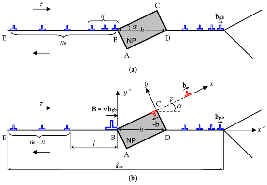
Figure 1.
Model of stress-stimulated transformation of a defect system in a non-equilibrium GB with a single NP ABCD and pile-ups of EGBDs at the NP and at the triple junction with adjacent GBs. (a) The initial state of the defect structure. To the right of the NP, there is a pile-up of some EGBDs pressed to the triple junction with adjacent GBs. To the left of the NP, there are n0 EGBDs, n of which have had enough time to form a pile-up pressed to the NP, while the others have had not the time to join the pile-up. (b) The emission of a lattice dislocation from the NP. The emission event is represented as the nucleation of a dipole of edge lattice dislocations at apex C of the NP. One dislocation with the Burgers vector b glides to the bulk of the grain, while the other one with the Burgers vector –b glides along the NP/grain interface and plays the role of a misfit dislocation. The pile-up of n EGBDs pressed to the NP is represented as an edge superdislocation with the Burgers vector B = nbgb to simplify calculations.
The elastic fields of a dilatational inclusion in the form of a long parallelepiped are determined by its shape and its own uniform three-dimensional dilatation ε* (see, for example, the review [33]). The value of dilatation ε* is given by the misfit f between the lattice parameters of the NP and the surrounding alloy, the difference in their thermal expansion coefficients, and the difference in the annealing and mechanical test temperatures.
The difference in the elastic moduli of the NP and the surrounding alloy is neglected here, with the assumption of the alloy to be an elastically isotropic homogeneous solid. In this case, the influence of the applied shear stress τ concentration at the NP edge can be neglected too, which allows us to remain in the framework of the analytical model.
According to the model [14], the Al2Cu NPs act as obstacles for the slip of the EGBDs along the GBs in the UFG Al-Cu-Zr alloy. Thus, the appearance of the NPs in the GBs leads to the formation of a GB defect structure which is characterized by pile-ups of the EGBDs pressed by an external shear stress τ to the NPs and to the triple junctions of adjacent GBs (Figure 1a). However, at low temperatures, the dislocation slip within GBs is slow, and not all EGBDs have enough time to approach the NP during the mechanical test. As a result, only a part of the EGBDs forms a pile-up at the NP, while the rest of the EGBDs remain distributed along the GB far from the NP (Figure 1b). In the model, the dislocation pile-up at the NP is modeled by an edge superdislocation with Burgers vector B (hereinafter, we call it B-superdislocation). The magnitude of the superdislocation Burgers vector is B = nbgb, where n is the number of the EGBDs in the dislocation pile-up at the NP (Figure 1b) and bgb is the magnitude of the Burgers vector of an EGBD.
Within the model, the combined action of the external shear stress τ, the shear stress field created by the NP, and the shear stress field created by the B-superdislocation at the NP leads to the emission of a lattice dislocation with Burgers vector b (b-LD) from apex C of the NP into the adjacent grain. The emission event can be modeled as the formation of the corresponding ±b-LD dipole (Figure 1b).
Within the model, let us calculate the energy characteristics of such an emission of a b-LD from the edge of the NP (Figure 1b). To calculate the energy characteristics, a semi-analytical energetic approach that is based on calculation of the total energy of the defect system was applied. In accordance with this approach, the total energy difference, which characterizes the defect structure after and before the lattice dislocation emission, is calculated. The lattice dislocation emission is considered to be energetically favorable if the total energy of the defect system decreases and energetically unfavorable if this emission leads to an increase in the total energy of the defect system. To simplify the calculations, the influence of the stress fields of the pile-up of the EGBDs near the GB triple junction and the EGBDs that locate far from the NP on the lattice dislocation emission is neglected. This approach seems reasonable enough because the main part of the EGBDs under consideration is located at a considerable distance from the point of the lattice dislocation emission, while the critical conditions for this emission are determined just at a small (on the order of 1 nm) displacement of the emitted lattice dislocations from point C.
The dislocation emission process is specified by the energy difference, , where and are the energies of the system in the initial state, before the b-LD emission (Figure 1a), and in its current state, after the lattice b-dislocation emission (Figure 1b), respectively. Such a transformation of the defect system is energetically favorable if .
where is the self-energy of the ±b-LD dipole, is the interaction energy between the B-superdislocation and the ±b-LD dipole, is the interaction energy between NP ABCD and the ±b-LD dipole, and denotes the interaction energy of the applied shear stress τ with the ±b-LD dipole.
Let us calculate the self-energy of the ±b-LD dipole in the coordinate system associated with it (Figure 1b). According to the Mura method [34], the energy can be expressed through the dislocation dipole stress tensor component as follows:
where is the cut-off radius of the stress fields of the ±b-LDs on their lines.
The expression for the component of the ±b-LD dipole in the coordinate system (Figure 1b) is given by the well-known formula [35]:
With Formula (3) substituted to Formula (2), we have the following:
where , G is the shear modulus, ν is the Poisson ratio, p is the path moved by the emitted b-LD (Figure 1b), and the term “1” in the brackets accounts for the core energies of the b-LD and –b-LD consisting of the lattice dislocation dipole.
For analyzing the interaction energies between different defects, a standard method of calculating the work spent to generate one defect in the stress field of another defect (or a group of defects) was used. In doing so, the interaction energy between the B-superdislocation and the ±b-LD dipole can be introduced as a work for the generation of the dipole of the ±b-LDs in the stress field of the B-superdislocation. It is given by the formula [34]:
where is the shear stress field that is created by the B-superdislocation and acts in the plane y = 0 (the gliding plane for the b-LD) of the coordinate system . Following [35], in the coordinate system presented in Figure 1b, the components of the B-superdislocation stress tensor that contribute to the shear stress can be written as follows:
These components of the B-superdislocation stress tensor cause the shear stress that acts in the gliding plane of the b-LD along the x-axis of the coordinate system.
The shear stress is expressed through the stress field components as follows:
where , , , and are given by , , , and .
As integration in Formula (5) is made along the x-axis of the coordinate system , one needs to rewrite the shear stress in this coordinate system with the help of the following relationships:
where and are as follows from the geometry in Figure 1b.
With the help of Formulas (7) and (8), in the new coordinate system , the shear stress acting along the plane y = 0 is given by the following formula:
With Formula (9) substituted into Formula (5), after integration, we obtain the expression for the interaction energy :
The energy that characterizes the elastic interaction between the NP and the ±b-LD dipole can be written in an integral form as follows [34]:
where is the shear component of the NP stress tensor, which acts on the b-LD during their motion along its slip plane y = 0 (Figure 1b). This shear stress in the coordinate system reads as follows [33]:
where and .
With Formula (12) substituted to Formula (11), after integration and some algebra, the interaction energy can be written as follows:
The energy that specifies the elastic interaction of the external shear stress τ with the dipole of the ±b-LDs is given by the following standard formula:
With Formulas (1)–(14), one can calculate the energy difference and find a critical stress τc that is the minimum stress required for the emission of a lattice dislocation from the NP. This stress is calculated from the conditions at nm and at nm that guarantee the barrier-less generation of the lattice dislocation. In the framework of the model, it is suggested that the maximum external shear stress τ acts along the considered GB with the NP (Figure 1). Taking this assumption into account, the critical level τc of the shear stress τ can be related to the yield stress as follows: .
3. Results
Based on the aforementioned theoretical model, we calculated a dependence of the yield stress on the number n of the EGBDs in the dislocation pile-up at the NP. The calculations were carried out for the following typical values of the system parameters [35,36]: GPa, , nm, , and nm. The emission angle α was chosen as the average angle between 0° and 45° that correspond to the maximum and minimum levels of the external shear stress τ, respectively. The dilatation eigenstrain ε* was taken as a mean lattice misfit of aluminium matrix and Al2Cu NP in two orthogonal orientations at interface (110)Al2Cu || (111)Al [21]: . The thermal expansion coefficient difference was neglected due to its relative smallness. Indeed, the corresponding contribution to the dilatation eigenstrain ε* is about of ≈ 6.86·10−4, where and are the thermal expansion coefficients of Al and Al2Cu, TAN is the annealing temperature, and Troom is room temperature.
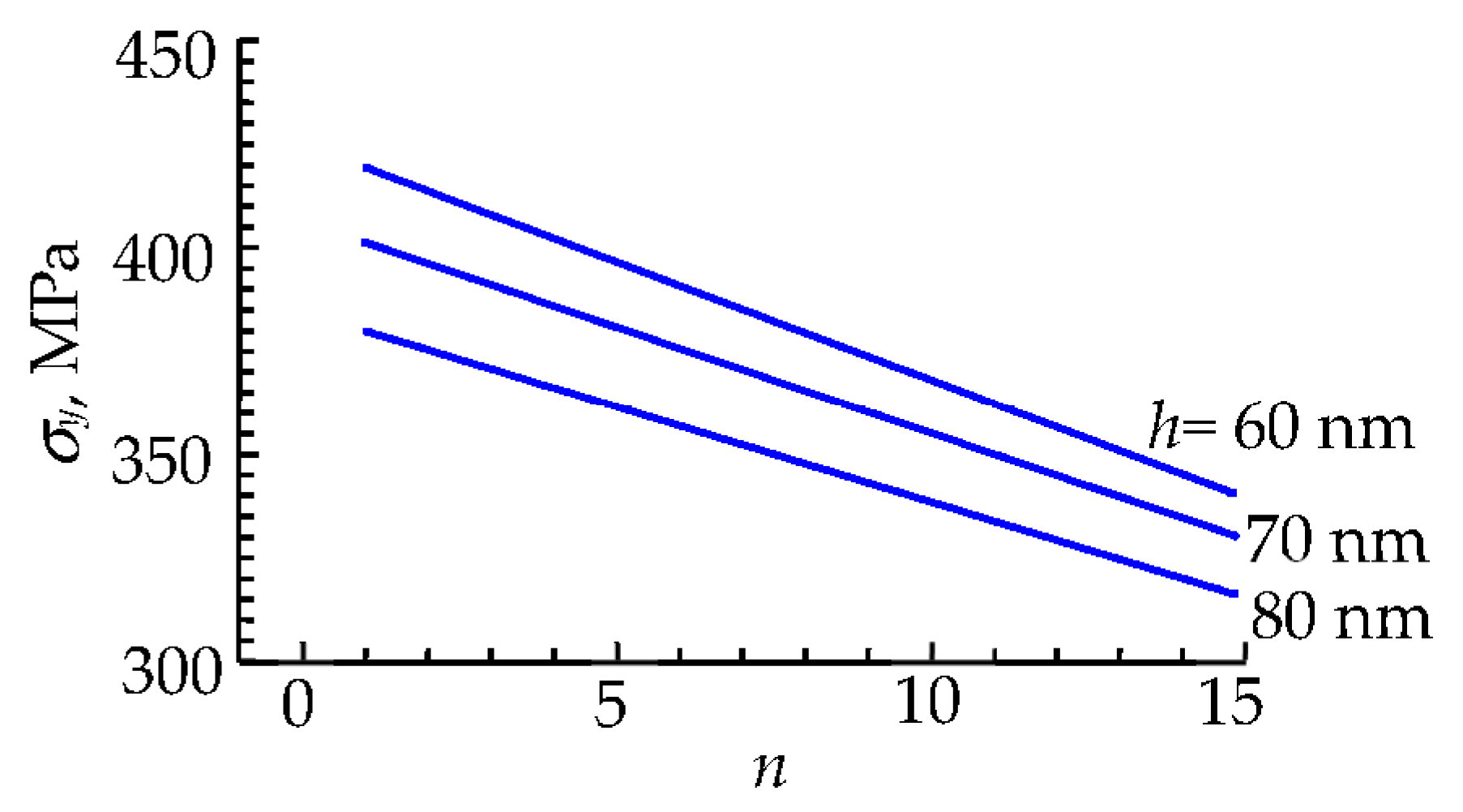
The results of calculations of the dependence are presented in Figure 2 for different values of the NP size: nm, 70 nm, and 80 nm. As follows from Figure 2, the yield stress decreases with increasing number n of the EGBDs in the dislocation pile-up at the NP and with an increase in the NP size h.

Figure 2.
Dependence of the yield stress on the number n of the EGBDs at the NPs for different values of the NP size, h = 60 nm, 70 nm, and 80 nm, at the following typical values of the system parameters: G = 27 GPa, ν = 0.33, a = 0.405 nm, b = a√2/2, bgb = 0.1 nm, f = 0.0147, and α = 22°.
To obtain the temperature dependences , we calculated the dependences of the number n of the EGBDs in the dislocation pile-up at the NP (which is modeled by a B-superdislocation, see Figure 1) on the deformation temperature for the HPT-processed UFG Al-Cu-Zr alloy after annealing (in the HPT-AN state) and for the HPT-processed UFG Al-Cu-Zr alloy after annealing and additional HPT deformation (in the HPT-AN-0.25HPT state). The calculations were carried out in the range of the deformation temperatures from 250 K to 293 K, since at lower temperatures (<250 K), the experimental curves change their slope [21], which indicates a change in the deformation mechanism controlling the thermally activated component of the yield stress in the UFG Al-Cu-Zr alloy.
The initial number n0 of the EGBDs on the left of the NP at room deformation temperature ( K) was assumed as for the HPT-AN state and for the HPT-AN-0.25HPT state. Within the model, these EGBDs are distributed along the segment EB of the GB, which is assumed to be equal to half of the average GB length, (Figure 1). The initial number of the EGBDs for the HPT-AN-0.25HPT state approximately corresponds to the case of a single NP in a GB, described in theoretical work [14]. The numbers 10 and 15 were selected due to the following reasons. Based on the total dislocation density Ldis = 3 × 10¹³ m−2 and the average grain size Dav. = 315 nm, experimentally measured in the HPT-AN-0.25HPT state of the alloy [13,21], one can estimate a number of dislocations per one grain: n ≈ Ldis × (Dav.)2 ≈ 30 μm−2 × 0.099 μm2 ≈ 3. Since the experiments have shown almost no lattice dislocations in the bulk of the grains [13,21], one can believe that they had been accepted by GBs in the process of HPT treatment and split in them into EGBDs with Burgers vectors of magnitude bgb ≈ b/3 ≈ 0.1 nm, where b is the Burgers vector magnitude of a perfect lattice dislocation. Therefore, one can estimate on average ngb ≈ 3 × 3 = 9 EGBDs per GB. However, in reality, some GBs can contain a larger number of EGBDs while others have a small number of them, and those with the larger number of EGBDs should always play the most active role as sources for lattice dislocations emitted into the bulk of surrounding grains. Thus, we have assumed that the GBs mostly enriched with EGBDs can contain ngb,max ≈ 3 × 9 = 27 ≈ 30 EGBDs. Since, in our model, the nanoprecipitate subdivides a GB into approximately equal parts, we finally took .
In a similar way, with Ldis = 1.7 × 10¹³ m−2 and Dav. = 360 nm, experimentally measured in the HPT-AN state of the alloy [13,21], one can estimate n ≈ Ldis × (Dav.)2 ≈ 17 μm−2 × 0.13 μm2 ≈ 2. Due to the same reasons as in the previous case, on average, ngb ≈ 2 × 3 = 6 EGBDs per GB. Therefore, the GBs most enriched with EGBDs can contain ngb,max ≈ 3 × 6 = 18 ≈ 20 EGBDs, and the one half gives n0′ = 10 in this case.
According to the model, the number n of the EGBDs in the dislocation pile-up at the NP decreases with a decrease in the deformation temperature (below 293 K) because as the deformation temperature drops, the dislocation activity decreases and fewer EGBDs are concentrated in the dislocation pile-up at the NP. At the same time, the total number of the EGBDs (for our case, in the HPT-AN state and in the HPT-AN-0.25HPT state) in the GB segment EB remains constant. Thus, each number n′ and n″ of the EGBDs for both the states of the HPT-processed UFG Al-Cu-Zr can be associated with a certain deformation temperature.
To construct the dependences and , let us estimate a characteristic distance l (see Figure 1) that determines the part of the GB segment EB along which are located the EGBDs that are able to effectively participate at a given deformation temperature in the formation of the pile-up at the NP. The distance l is given by the following:
where is the deformation time required to reach the experimental value of the yield stress and V is the velocity of thermally activated dislocation glide.
Following the approach in [37], the velocity of thermally activated dislocation glide can be expressed by the standard formula:
where is the temperature-dependent factor [37], E is the energy of kink formation and migration along the EGBD line, is the distance between adjacent Peierls valleys within the GB [37], is the distance between the stable positions of a kink along the EGBD line [37], is the Debye frequency, and J/K is the Boltzmann constant. According to the experimental work [21], the deformation time is equal to 4 s. Following the work [17], the energy E of kink formation and migration along the EGBD line can be estimated as E = 0.5 eV.
Then, the numbers n′ and n″ of the EGBDs for both the states of the HPT-processed UFG Al-Cu-Zr are given by the following expressions:
where ≈ 300 nm [21].
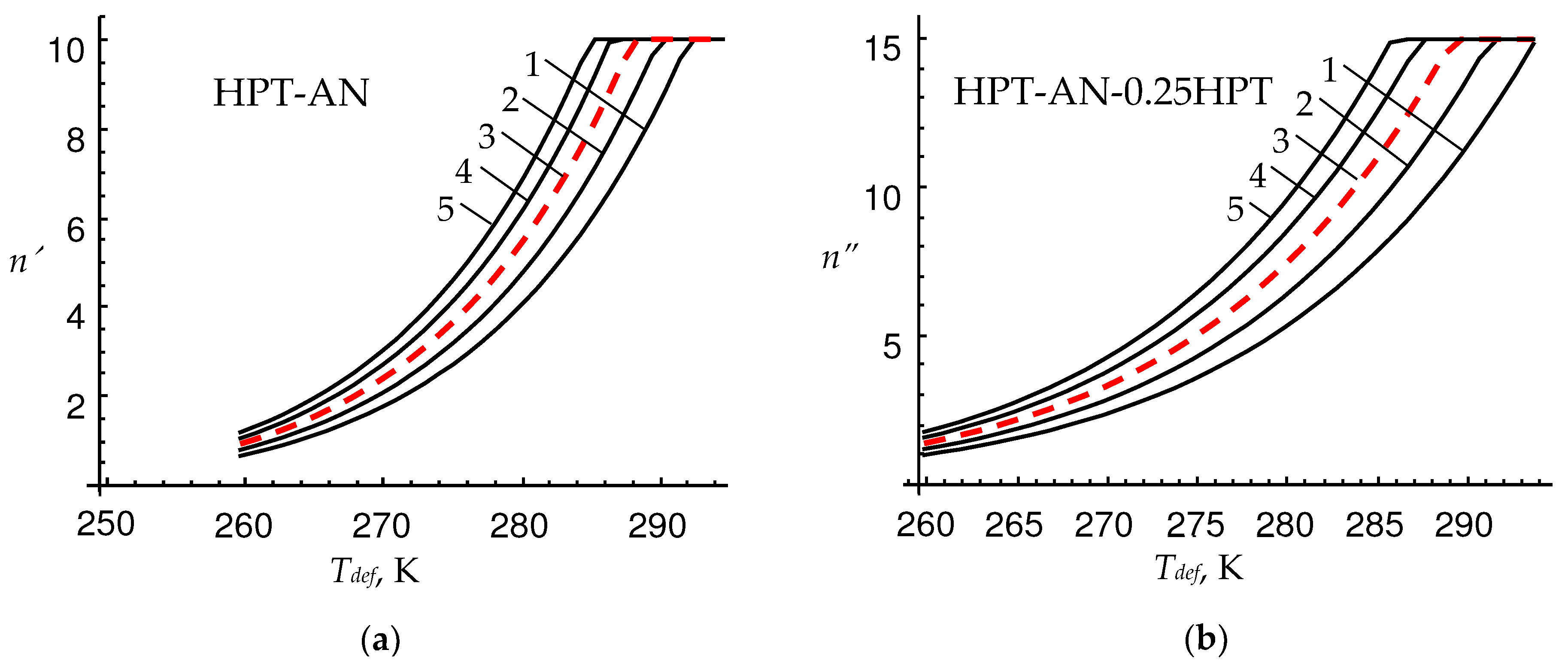
Using Formulas (15)–(18), we calculated the dependences and at various values of the external shear stress τ. These dependences allow us to determine the numbers n′ and n″ of the EGBDs in the pile-up at the NP for both the states of the HPT-processed UFG Al-Cu-Zr for certain deformation temperatures. The curves and are shown in Figure 3 for the HPT-AN state at different values of the external shear stress of τ = 150, 175, 200, 225, and 250 MPa (Figure 3a), and for the HPT-AN-0.25HPT state at τ = 125, 150, 175, 200, and 225 MPa (Figure 3b), respectively, of the HPT-processed UFG Al-Cu-Zr alloy. The ranges of the external shear stress τ were chosen to correspond to the ranges of the experimental values [21] of the yield stress that is estimated as in our model.

Figure 3.
Dependences of the numbers n′ and n″ of the EGBDs at the NPs on the deformation temperature for the (a) HPT-AN and (b) HPT-AN-0.25HPT states of the HPT-processed UFG Al-Cu-Zr alloy at different values of the external shear stress: (a) τ = 150 (curve 1), 175 (2), 200 (3), 225 (4), and 250 MPa (5), and (b) τ = 125 (curve 1), 150 (2), 175 (3), 200 (4), and 225 MPa (5). Red dashed lines correspond to the average values of the external shear stress.
As is seen from Figure 3, the numbers n′ and n″ of the EGBDs increase with the deformation temperature in both the states of the HPT-processed UFG Al-Cu-Zr alloy. The dependences and that correspond to the different values of the external shear stress τ are close to each other. For convenience, they are approximated by the average red dashed lines (Figure 3). These red dashed lines correspond to the average experimental values of the yield stress in the deformation temperature range 250 K < Tdef < 293 K. In the framework of the model, for each value of the deformation temperature, the numbers n′ and n″ of the EGBDs in the pile-up at the NP are determined for the level of the external shear stress τ that corresponds to these average experimental values of the yield stress.
As follows from Figure 3, the dependences and reach saturation at certain deformation temperatures (close to the room temperature) as the number of the EGBDs in the GB segment EB is limited by for the HPT-AN state (Figure 3a) and for the HPT-AN-0.25HPT state (Figure 3b). Also, it follows from the dependences in Figure 3 that the numbers n′ and n″ of the EGBDs, which can glide along the GB segment EB and form the pile-up of the EGBDs at the NP, turn to zero at the deformation temperatures K. In this case, ( K), our model stops working because the deformation of the HPT-processed UFG Al-Cu-Zr alloy occurs due to the action of other mechanisms.
Further, with the help of the dependences (Figure 2), (Figure 3a), and (Figure 3b), we calculated the dependences and of the theoretical yield stress on the deformation temperature for the HPT-AN and HPT-AN-0.25HPT states of the HPT-processed UFG Al-Cu-Zr alloy, respectively. These dependences were obtained by relating the deformation temperature from Figure 3 to the yield stresses from Figure 2 through each value of the numbers n′ and n″ of the EGBDs.
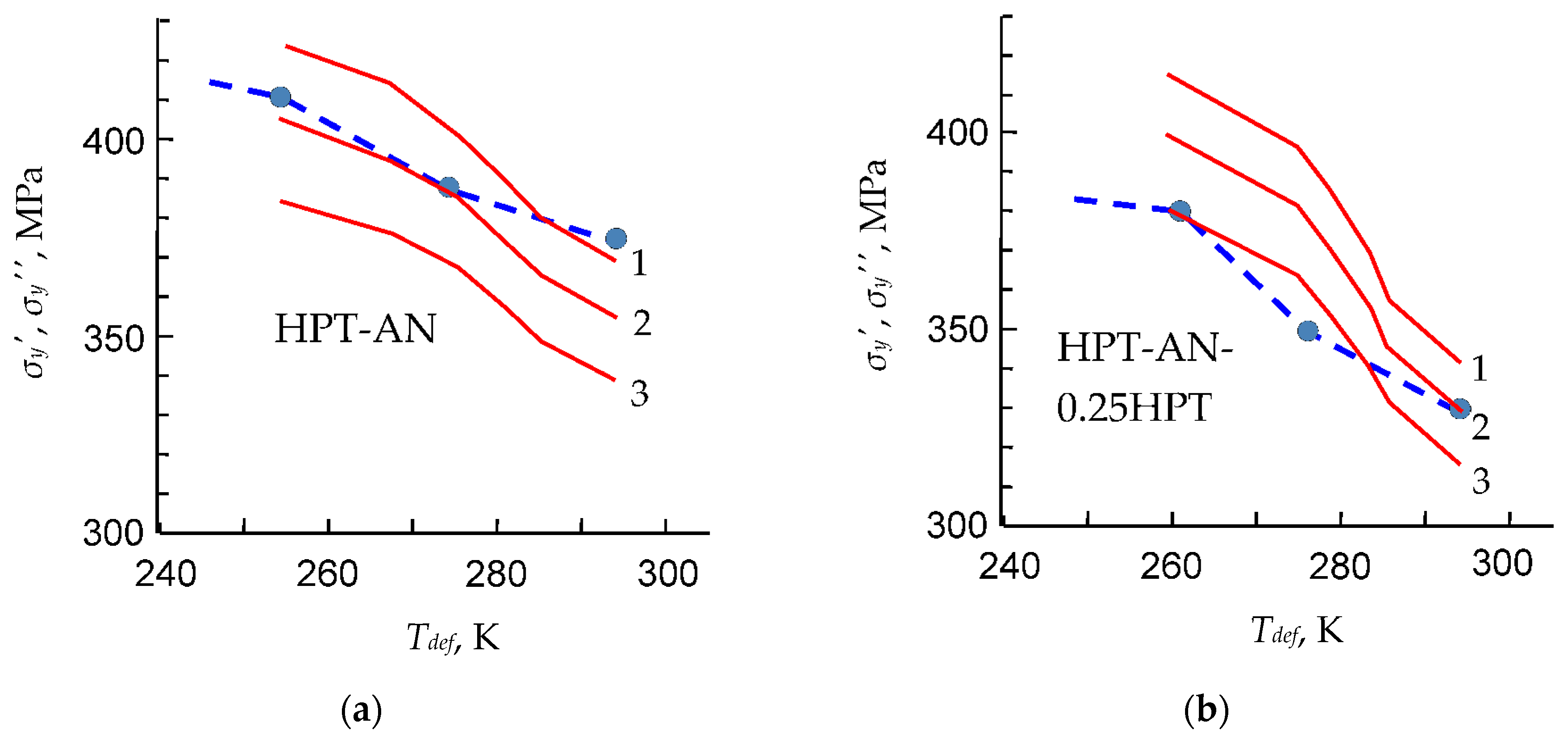
The dependences and are shown in Figure 4 for the HPT-AN (Figure 4a) and HPT-AN-0.25HPT (Figure 4b) states at various values of the NP size h = 60 nm (curve 1), 70 nm (curves 2), and 80 nm (curves 3) in comparison with experimental data [21] (dashed curves). As is seen from Figure 4, the yield stress decreases with the increases in both the deformation temperature and NP size h. These theoretical results demonstrate that an increase in the yield stress with a drop in the deformation temperature is associated with a decrease in the number n of the EGBDs near the NPs. Thus, the deformation temperature has a significant effect on the yield stress of HPT-proceed Al-Cu-Zr alloy due to its influence on the dislocation activity in GBs.
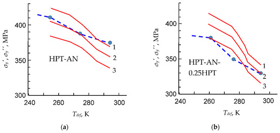
Figure 4.
Dependences of the yield stresses and on the deformation temperature for different values of the NP size h = 60 nm (curve 1), 70 nm (2), and 80 nm (3) for the (a) HPT-AN and (b) HPT-AN-0.25HPT states of the HPT-processed UFG Al-Cu-Zr alloy. For comparison, the theoretical (red solid curves) and experimental (blue dashed curves with circles taken from Ref. [21]) dependences are shown.
It is also seen that our theoretical results (solid curves) demonstrate reasonable agreement with experimental curves of work [21] for both states of the HPT-proceed Al-Cu-Zr alloy.
4. Conclusions
Thus, a theoretical model that describes the effect of the deformation temperature on the yield stress in the high-pressure torsion (HPT)-processed Al-Cu-Zr alloy after annealing and after annealing and additional HPT deformation is developed. Within the model, the plastic deformation occurs due to the emission of lattice dislocations from the edges of faceted nanoprecipitates at grain boundaries in the presence of a number of extrinsic grain boundary dislocations in the pile-ups at the nanoprecipitates. It is assumed that the number of these dislocations in the pile-ups at the nanoprecipitates decreases with a decrease in the deformation temperature. As a result, a decrease in the dislocations number provides an increase in the contribution of the external shear stress τ to the critical shear stress τc, thus leading to an increase in the yield strength of the Al-Cu-Zr alloy. Thus, a decrease in the deformation temperature results in an increase in the yield stress of the HPT-processed Al-Cu-Zr in the case of both states of the deformation-heat treatment. These theoretical results well correspond to experimental data in Ref. [21].
We hope that our model will be applicable for other ultrafine-grained alloys processed with severe plastic deformation methods that have similar structural characteristics such as low density of lattice dislocations inside grains and non-equilibrium grain boundaries containing mobile extrinsic grain boundary dislocations and faceted nanoprecipitates able to be sources of lattice dislocations.
Author Contributions
Conceptualization, M.Y.G.; methodology, M.Y.G. and N.V.S.; investigation, N.V.S.; validation, T.S.O., M.Y.G. and N.V.S.; data curation, M.Y.G. and N.V.S.; formal analysis, N.V.S.; writing—original draft preparation, T.S.O., M.Y.G. and N.V.S.; writing—review and editing, T.S.O., M.Y.G. and N.V.S.; supervision, M.Y.G.; funding acquisition, T.S.O. All authors have read and agreed to the published version of the manuscript.
Funding
This research was funded by the Russian Science Foundation, grant number 22-19-00292.
Data Availability Statement
The data are available on request from the corresponding author.
Conflicts of Interest
The authors declare no conflict of interest.
References
- Agarwal, K.M.; Tyagi, R.K.; Choubey, V.; Saxena, K.K. Mechanical behaviour of Aluminium Alloy AA6063 processed through ECAP with optimum die design parameters. Adv. Mater. Process. Technol. 2022, 8, 1901–1915. [Google Scholar] [CrossRef]
- Mathew, R.T.; Singam, S.; Ghosh, P.; Masa, S.K.; Prasad, M.J.N.V. The defining role of initial microstructure and processing temperature on microstructural evolution, hardness and tensile response of Al-Mg-Sc-Zr (AA5024) alloy processed by high pressure torsion. J. Alloys Compd. 2022, 901, 163548. [Google Scholar] [CrossRef]
- Suresh, M.; Sharma, A.; More, A.M.; Kalsar, R.; Bisht, A.; Nayan, N.; Suwas, S. Effect of equal channel angular pressing (ECAP) on the evolution of texture, microstructure and mechanical properties in the Al-Cu-Li alloy AA2195. J. Alloys Compd. 2019, 785, 972–983. [Google Scholar] [CrossRef]
- Lanjewar, H.; Naghdy, S.; Vercruysse, F.; Kestens, L.A.; Verleysen, P. Severe plastically deformed commercially pure aluminum: Substructure, micro-texture and associated mechanical response during uniaxial tension. Mater. Sci. Eng. A 2019, 764, 138195. [Google Scholar] [CrossRef]
- Edalati, K.; Bachmaier, A.; Beloshenko, V.A.; Beygelzimer, Y.; Blank, V.D.; Botta, W.; Bryła, K.; Čížek, J.; Divinski, S.; Enikeev, N.A.; et al. Nanomaterials by severe plastic deformation, Review of historical developments and recent advances. Mater. Res. Lett. 2022, 10, 163–256. [Google Scholar] [CrossRef]
- Alawadhi, M.Y.; Sabbaghianrad, S.; Huang, Y.; Langdon, T.G. Evaluating the paradox of strength and ductility in ultrafine-grained oxygen-free copper processed by ECAP at room temperature. Mater. Sci. Eng. 2021, 802, 140546. [Google Scholar] [CrossRef]
- Ovid’ko, I.A.; Valiev, R.Z.; Zhu, Y.T. Review on superior strength and enhanced ductility of metallic nanomaterials. Prog. Mater. Sci. 2018, 94, 462–540. [Google Scholar] [CrossRef]
- Wu, S.H.; Xue, H.; Yang, C.; Kuang, J.; Zhang, P.; Zhang, J.Y.; Li, Y.J.; Roven, H.J.; Liu, G.; Sun, J. Hierarchical structure in Al-Cu alloys to promote strength/ductility synergy. Scr. Mater. 2021, 202, 113996. [Google Scholar] [CrossRef]
- Boillat, R.; Isanaka, S.P.; Liou, F. The effect of nanostructures in aluminum alloys processed using additive manufacturing on microstructural evolution and mechanical performance behavior. Crystals 2021, 11, 524. [Google Scholar] [CrossRef]
- Youssef, K.M.; Scattergood, R.O.; Murty, K.L.; Koch, C.C. Nanocrystalline Al–Mg alloy with ultrahigh strength and good ductility. Scr. Mater. 2006, 54, 251–256. [Google Scholar] [CrossRef]
- Zhu, Y.; Wu, X. Heterostructured materials. Prog. Mater. Sci. 2023, 131, 101019. [Google Scholar] [CrossRef]
- Wang, G.; Ouyang, H.; Su, Y.; Guo, Q.; Xiong, D.B.; Zhuang, Q.; Yue, Z.; Li, Z.; Zhang, D. Heterostructured bulk aluminum with controllable gradient structure: Fabrication strategy and deformation mechanisms. Scr. Mater. 2021, 196, 113762. [Google Scholar] [CrossRef]
- Orlova, T.S.; Sadykov, D.I.; Danilov, D.V.; Enikeev, N.A.; Murashkin, M.Y. Ultrafine-grained Al-Cu-Zr alloy with high-strength and enhanced plasticity. Mater. Lett. 2021, 330, 130490. [Google Scholar] [CrossRef]
- Gutkin, M.Y.; Orlova, T.S.; Skiba, N.V. Micromechanism of plastic deformation enhancement in ultrafine-grained Al-Cu-Zr alloy after annealing and additional deformation. Phys. Solid State 2023, 65, 840–844. [Google Scholar] [CrossRef]
- Borovikov, V.; Mendelev, M.I.; King, A.H. Solute effects on interfacial dislocation emission in nanomaterials: Nucleation site competition and neutralization. Scr. Mater. 2018, 154, 12–15. [Google Scholar] [CrossRef]
- Peng, S.; Wei, Y.; Gao, H. Nanoscale precipitates as sustainable dislocation sources for enhanced ductility and high strength. Proc. Natl. Acad. Sci. USA 2020, 117, 5204–5209. [Google Scholar] [CrossRef] [PubMed]
- Orlova, T.S.; Mavlyutov, A.M.; Gutkin, M.Y. Suppression of the annealing-induced hardening effect in ultrafine-grained Al at low temperatures. Mater. Sci. Eng. A 2021, 802, 140588. [Google Scholar] [CrossRef]
- Li, S.-S.; Yue, X.; Li, Q.-Y.; Peng, H.-L.; Dong, B.-X.; Liu, T.-S.; Yang, H.-Y.; Fan, J.; Shu, S.-L.; Qiu, F.; et al. Development and applications of aluminum alloys for aerospace industry. J. Mater. Sci. Technol. 2023, 27, 944–983. [Google Scholar] [CrossRef]
- Son, K.; Kassner, M.E.; Lee, T.K.; Lee, J.W. Mg effect on the cryogenic temperature toughness of Al-Mg alloys. Mater. Des. 2022, 224, 111336. [Google Scholar] [CrossRef]
- Park, W.S.; Chun, M.S.; Han, M.S.; Kim, M.H.; Lee, J.M. Comparative study on mechanical behavior of low temperature application materials for ships and offshore structures: Part I—Experimental investigations. Mater. Sci. Eng. A 2011, 528, 5790–5803. [Google Scholar] [CrossRef]
- Orlova, T.S.; Sadykov, D.I.; Danilov, D.V.; Murashkin, M.Y. Influence of decreased temperature on the plasticization effect in high-strength Al-Cu-Zr Alloys J. Alloys Compd. 2023, 931, 167540. [Google Scholar] [CrossRef]
- Zhang, X.R.; Sun, G.X.; Zai, W.; Jiang, Y.; Jiang, Z.H.; Han, S.; Bi, G.L.; Fang, D.Q.; Lian, J.S. Effects of temperature and strain rate on deformation behaviors of an extruded Mg-5Zn-2.5 Y-1Ce-0.5 Mn Alloys. Mater. Sci. Eng. A 2021, 799, 140141. [Google Scholar] [CrossRef]
- Davoudi, K. Temperature dependence of the yield strength of aluminum thin films: Multiscale modeling approach. Scr. Mater. 2017, 131, 63–66. [Google Scholar] [CrossRef]
- Cereceda, D.; Diehl, M.; Roters, F.; Raabe, D.; Perlado, J.M.; Marian, J. Unraveling the temperature dependence of the yield strength in single-crystal tungsten using atomistically-informed crystal plasticity calculations. Int. J. Plasticity 2016, 78, 242–265. [Google Scholar] [CrossRef]
- Wong, S.L.; Laptyeva, G.; Brüggemann, T.; Engler, O.; Roters, F.; Raabe, D.; Karhausen, K.-F. Microchemistry-dependent simulation of yield stress and flow stress in non-heat treatable Al sheet alloys. Model. Simul. Mater. Sci. Eng. 2020, 28, 035010. [Google Scholar] [CrossRef]
- Mohles, V.; Li, X.; Heering, C.; Hirt, G.; Bhaumik, S.; Gottstein, G. Validation of an improved dislocation density based flow stress model for Al-alloys. Int. J. Mater. Form. 2008, 1, 77–80. [Google Scholar] [CrossRef]
- Leyson, G.P.M.; Hector, L.G., Jr.; Curtin, W.A. Solute strengthening from first principles and application to aluminum alloys. Acta Mater. 2012, 60, 3873–3884. [Google Scholar] [CrossRef]
- Howe, J.M.; Benson, W.E.; Garg, A.; Chang, Y.C. In situ hot-stage high-resolution transmission electron microscopy of interface dynamics during growth and dissolution of (111){alpha}{theta}-Al {sub 2} Cu plates in an Al-Cu-Mg-Ag Alloys. Mater. Sci. Forum 1995, 255, 189–190. [Google Scholar]
- Wang, S.J.; Liu, G.; Wang, J.; Misra, A. Characteristic orientation relationships in nanoscale Al-Al2Cu eutectic. Mater. Character. 2018, 142, 170–178. [Google Scholar] [CrossRef]
- Liu, G.; Gong, M.; Xie, D.; Wang, J. Structures and mechanical properties of Al-Al2Cu interfaces. JOM 2019, 71, 1200–1208. [Google Scholar] [CrossRef]
- Zhou, Q.; Hua, D.P.; Du, Y.; Ren, Y.; Kuang, W.W.; Xia, Q.S.; Bhardwaj, V. Atomistic study of atomic structures and dislocation nucleation at Al/Al2Cu interfaces. Int. J. Plast. 2019, 120, 115–126. [Google Scholar] [CrossRef]
- Liu, G.; Wang, S.; Misra, A.; Wang, J. Interface-mediated plasticity of nanoscale Al–Al2Cu eutectics. Acta Mater. 2020, 186, 443–453. [Google Scholar] [CrossRef]
- Ovid’ko, I.A.; Sheinerman, A.G. Elastic fields of inclusions in nanocomposite solids. Rev. Adv. Mater. Sci. 2005, 9, 17–33. [Google Scholar]
- Mura, T. The Continuum Theory of Dislocations. In Advances in Material Research; Herman, H., Ed.; Interscience: New York, NY, USA, 1968; Volume 3, pp. 1–108. [Google Scholar]
- Hirth, J.P.; Lothe, J. Theory of Dislocations; Wiley: New York, NY, USA, 1982. [Google Scholar]
- Smithells, C.J.; Brands, E.A. Metals Reference Book; Butterworths: London, UK, 1976. [Google Scholar]
- Chan, S.W.; Boyko, V.S. Mobility of grain boundary dislocations during the conservative untwisting of [001] twist boundaries. Phys. Rev. B 1996, 53, 16579. [Google Scholar] [CrossRef] [PubMed]

Disclaimer/Publisher’s Note: The statements, opinions and data contained in all publications are solely those of the individual author(s) and contributor(s) and not of MDPI and/or the editor(s). MDPI and/or the editor(s) disclaim responsibility for any injury to people or property resulting from any ideas, methods, instructions or products referred to in the content. |
© 2023 by the authors. Licensee MDPI, Basel, Switzerland. This article is an open access article distributed under the terms and conditions of the Creative Commons Attribution (CC BY) license (https://creativecommons.org/licenses/by/4.0/).