Abstract
The interest in the crystallography of structural transformations is driven by emerging capabilities in texture control and by the resulting anisotropy of the physical-mechanical properties of functional materials and products. The recrystallization texture of cold-drawn Cu and Al samples after recrystallization annealing at different temperatures was studied using EBSD. Equivalent deformation textures of Al and Cu are transformed into different recrystallization textures. The recrystallization nuclei in Al are formed at high-angle boundaries between deformed grains close to Σ3 CSL boundaries. The recrystallization nuclei in Cu are formed inside the deformed grains at twin boundaries (Σ3). The recrystallization nuclei in both Al and Cu are the crystallites whose boundaries approximately correspond to misorientation rotated about the <772> axis at an angle of 52–70° from a deformed matrix. The physical interpretation of the results will allow for the development of new models and the enhancement of existing models of texture inheritance.
1. Introduction
The majority of technologies for producing components of metal materials include deformation, during which a change in semi-product geometry is accompanied by the formation of a crystallographic texture. Practical interest in textures appears due to the fact that they result in anisotropy of physical properties, strength, and ductility, as well as a material tendency towards failure [1,2,3,4,5,6]. There are certain mechanisms of texture inheritance [7,8] in the course of the manufacturing process during such treatments as recrystallization, annealing, deformation, et al. In a narrow sense, texture inheritance is the reproduction of the prior texture in the final stages of the material treatment. In a wider sense, this is a relationship between the textures in the material at different stages of its treatment. An understanding of the features of the origination and development of texture, along with the resulting mechanical property anisotropy, will make it possible to improve existing technologies or create a basis for developing new ones. Therefore, the problem of obtaining interconnected information about the evolution of structure-texture conditions during the production of materials and objects needs additional comprehension.
Tailoring the orientation-dependent physical, mechanical, and functional properties of materials and products is impossible without understanding the patterns of reorientation of the crystal lattice of metal or alloy during deformation and subsequent recrystallization annealing [9,10]. The establishment of strict rules for grain evolution is important for understanding the crystallographic mechanisms of structural transformations at the interatomic interaction scale [6,11].
The main cause of the appearance of texture during the processing of metals is the deformation under constrained conditions corresponding to a certain stress state [8,12]. The directional action on metallic material leads to the deformation of all its crystallites through the sliding of dislocation systems with maximum activity [13]. With a given stress state in the deformation scheme, a set of discrete grain orientations is formed. These orientations are disoriented with respect to each other and form a complex texture [14,15]. One should note that a certain fraction of texture components formed during deformation in metals with cubic lattices is determined by their symmetrical arrangement relative to the external stress state [8,15]. It is also important to emphasize that theoretically calculated deformation textures usually find experimental confirmation [15,16,17,18,19,20,21]. The emergence of a limited number of preferential crystalline orientations leads to the formation of local-specific misorientations between them. These specific misorientations correspond to boundaries in the lattice system of coincident site lattice (CSL) boundaries [7,22]. The formation of special boundaries must be preceded by the occurrence of special misorientations—mutual arrangements of two crystal lattices described by a common site and rotation about a certain crystallographic axis. These transformations result in the formation of so-called 3D CSL. The ratio of the volumes of the elements of the coinciding site lattice and the original lattice is characterized by the parameter Σn—identified as an inverse spatial density of the coinciding sites; where n takes the value of 3, 5, 7, 9, etc., i.e., matches every third, fifth, etc. coinciding sites.
Unlike deformation processes, for which texture formation is often predictable (given a certain scatter degree), recrystallization processes are much more complicated in terms of the prediction of texture transformation [23]. Deformation texture generally transforms into recrystallization texture during annealing. The main orientations of this texture are associated with the initial rotations around the axes parallel to the applied stresses at certain angles [1,7]. The crystallographic orientations of neighboring grains determine the structure of the boundary between them and, accordingly, whether the boundary is mobile or stationary. Thus, the evolution of the entire system is defined by the process of grain boundary formation. Thus, the possibility and direction of recrystallization processes and phase transformations [24,25,26] depend on the orientation of the neighboring grains.
Modern experimental methods of studying the texture of the material (based on electron back scattered diffraction (EBSD) [27,28,29,30]) allow for tracking the movement of boundaries between elements of the mesostructure during recrystallization. This opens the possibility of describing boundary displacement at the level of sliding and dislocation gliding, which enables the explanation of recrystallization processes using the evolution of special boundaries approach. The local texture determines the structure of the boundary between two neighboring crystallites and governs the direction of recrystallization. In this context, modern research on the crystallographic aspects of recrystallization nuclei as well as the correlation of deformation orientations with orientations of primary recrystallization (PR) and then PR orientations with orientations of either normal or abnormal grain growth has come to the foreground [7].
Works [2,7,30,31,32,33,34], as well as the authors’ works [10,35,36], show the possibility of predicting material texture using special boundaries (CSL boundaries), which play a dominant role in structural transformations. At present, an intense discussion of the role of special boundaries in the formation of nuclei during secondary recrystallization takes place [37,38,39]. It is obvious that the appearance of special boundaries between the neighboring crystallites must be preceded by the formation of special misorientations. The role of special boundaries in the formation of the texture of secondary recrystallization in the material with a body-centered cubic (BCC) lattice (Fe-3%Si alloy) is considered in [37,38]. The orientations of recrystallized grains are connected with the orientations of deformed grains by rotations at certain angles around the <110> crystallographic axes. The formation of recrystallization texture is explained by the movement of such special boundaries as Σ9, Σ11. Their appearance is preceded by the formation of corresponding special misorientations between the components of the deformation texture.
The work [40], which highlights atomic simulation of crystallographic orientations of grains in thermomechanical and isothermal processing of Al, shows that with increasing duration of processes, the evolution of boundaries mainly develops through increasing the fraction of special low-energy orientations Σ3 and Σ11 by reducing the fraction of high-energy boundary Σ25b.
Understanding the processes of texture transformation during recrystallization is an important and unresolved task. However, it remains almost impossible to predict neither the annealing texture nor the degree of its scattering. The reason for this uncertainty is the lack of knowledge about some microstructural details of the deformed state and the recrystallization process in general [7].
It is well known that in BCC metals, the main stable component of texture formed during deformation under tensile stresses is characterized by axis <110> [41]. In face-centered cubic (FCC) metals, the deformation texture is characterized by two components close to <100> and <111> [42,43,44]. The ratios between these components, both in deformation and recrystallization, depend on stacking fault energy (SFE), which also determines the material’s tendency for deformation twinning [27,29,45]. In particular, Al is a metal with high SFE (~135 mJ/m2 [46]) and is characterized by a high stability of ˂111> component in comparison with ˂100> component [8].
This work offers a comparative analysis of crystallographic patterns of primary recrystallization behavior in metals with various SFE in order to determine the possible role of special boundaries in structural transformation processes.
2. Materials and Methods
Wires made from commercially pure copper and aluminum have been used as research materials since these metals have significantly different SFEs.
M001-grade wire, an analogue of electrolytic Tough Pitch copper (ETP), was investigated. Wire of 1.38 mm in diameter was obtained from an 8 mm copper rod at the MSM 85 multipass drawing machine (Maschinenfabrik Niehoff GmbH & Co., Singapore) per 12 passes at the drawing speed of the latter intermediate block of 20 m/s. No intermediate annealing was performed during the drawing. Tandem drawing was carried out through a set of polycrystalline dies. At the cold deformation stage, the total strain accumulated after 12 drawing passes amounted to 33.61, which was equal to the logarithmic strain of 3.51 and the area reduction (RA) of 97.02%. The drawing was followed by recrystallization annealing by means of continuous induction-controlled heating and cooling to temperatures of 300–550 °C with a step of 50 °C and a heating/cooling rate of 100 °C/s.
A wire made of commercially pure aluminum (AD0 grade) with a diameter of 4.00 mm was cold-rolled in calibrated rolls of circular cross-section. The accumulated reduction area was 90%. Sufficiently long samples were exposed to annealing in gradient furnaces at temperature intervals of 0.2–0.5 Tm (melting temperature) to obtain both recrystallized and intermediate states. Aluminum wire samples were annealed from 150 to 550 °C for 30 min after deformation to analyze the textural state of recrystallization. The annealing was carried out in a muffle tube furnace with area heating. Wire samples in an intermediate state (annealed at 200 °C) and at a maximum temperature of 550 °C were also investigated.
Metallographic sections were made for orientation microscopy on all annealed copper and aluminum samples in order to estimate the degree of recrystallization. The following three groups of samples were characterized by the following criteria: (1) No recrystallized grains were found; (2) the process of primary recrystallization has begun (the fraction of recrystallized grains was about 10%); and (3) the process of primary recrystallization is complete, though normal grain growth is not observed.
Samples for metallography were mechanically grinded and polished using diamond paste on Struers LaboPol 5 (Struers ApS, Ballerup, Denmark). Final polishing was carried out on colloidal silica for 45 min. Copper samples were electropolished in a solution consisting of 500 mL distilled water, 250 mL H3PO4, 250 mL ethanol, 50 mL propanol, and 5 g carbamide at a voltage of 5 V and a temperature of 5 °C for 1 min; Aluminum samples were electropolished in a solution consisting of 750 mL methanol and 250 mL HNO3 at a voltage of 20 V and a temperature of 20 °C for 1 min.
The texture analysis was carried out using electron back scattered diffraction (EBSD) on a double beam electron-ion microscope (ZEISS CrossBeam AURIGA) with hardware and software suite for registration and analysis of diffraction patterns in an Inca system with an Oxford Instruments analyzer (Carl Zeiss NTS, Oberkochen, Germany). Kikuchi bands in the EBSD pattern were analyzed using Nordlys HKL Channel 5 software. The scanning step was 0.1 µm, and the error in determining the crystal lattice orientation amounted to ±1°. Areas for EBSD analysis were set in order to include the entire cross-section of the samples. The percentage of recognition was more than 70%; therefore, one map accounted from 600,000 to 1,700,000 data points. The total number of analyzed grains for several maps is: for Al in the deformed state ~104, for Al in the recrystallized state ~103; for Cu in the deformed state ~104, for Cu in the recrystallized state ~2.5 ×·103. Orientation distribution functions (ODFs) and boundary distribution histograms were built for all the received data. Low-angle boundaries (from 2° to 15°) between local volumes were plotted on orientation maps with thin lines. Boundaries with misorientations greater than 15 degrees were marked with thick lines.
In texture analysis, two types of sections of ODF were used (Figure 1a–r) in addition to orientation maps: (1) Projections of pole exits, which show all orientations present in the analyzed area (Figure 1a,b,e,f,k,l,o,p); and (2) Distributions of pole density, which show the most pronounced (“strong”) orientations and their scattering degree (Figure 1c,d,g,h,m,n,q,r).
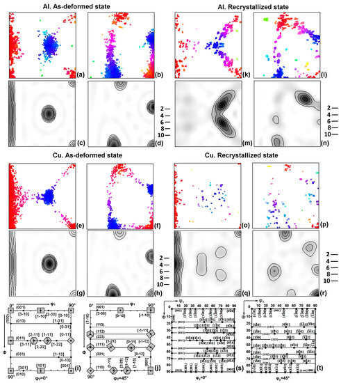
Figure 1.
ODF sections from deformed (a–h) and recrystallized (k–r) Al (k–n) and Cu (o–r): (a,c,e,g,k,m,p,q)—φ2 = 0°; (b,d,f,h,l,n,p,r)—φ2 = 45°. (i,j,s,t)—φ2 = 0° φ2 = 45° ODF sections show some main (i,j) and many possible (s,t) texture components used to identify the texture.
The Brandon standard criterion ±∆Θ built-in in EBSD software (HKL Channel5 version 5.12.73.0, Oxfordshire, Abingdon, UK) was used to verify the special boundaries between individual grains. For each boundary, it is calculated from ∆Θ = 15°/(Σn)1/2, where Σn is the number of coincident sites in superimposed three-dimensional crystal lattices.
3. Results
According to different studies [44,47], including the authors’ ones, the central regions (≤1/2 Ø) of the samples after deformation are characterized by almost equivalent fiber texture with axes <111> (strong component) and <100> (weak component).
Crystallographic texture is complex fiber within the product as a result of the deformation symmetry [44]. However, taking into account the analyzed sections of the samples (the section plane is parallel to the axis of the wire; the axis belongs to a given plane) and the small area for EBSD analysis, texture at this scale can be considered to consist of a discrete set of components characterized by a specified plane and direction. The latter allows for establishing a crystallographic relationship between them using standard designations of individual components.
In a given coordinate system: rolling direction (RD) (drawing direction (DD)) ‖ X, normal direction (ND) ‖ Y, deformation fiber texture for both Al and Cu can be shown as limited, i.e., consisting of components that smoothly transit into each other in quite specific directions: the stronger (011) [], (110) [], (112) [], () [], and the weaker (011) [100], {100} <001> (Figure 1a–h).
The spectrum of grain boundaries reveals that after deformation, all types of boundaries are present, yet the majority are low-angle grain boundaries (LAGBs) and high-angle grain boundaries (HAGBs), ranging from 52° to 60° (Figure 2a,b). Among the specific misorientations (Figure 2c,d), CSL Σ3 boundaries are predominant (Table 1). The fraction of CSL boundaries during structural transformation increases. The length of Σ3 boundaries in the total length of grain boundaries of recrystallized Cu is significantly higher (Table 1) compared to Al, which is attributed to the lower SFE and formation of annealing twins. The formation of Σ3 boundaries directly suggests that the primary texture components are orientations in twin misorientations relative to one another. CSL boundaries such as Σ9, Σ11, Σ17b, Σ25b, Σ33c, Σ41c, Σ43c, and Σ45c are also commonly observed. These boundaries are characterized by a rotation axis about <110> or one close to it. It should be noted that the twin boundary Σ3 is most often characterized by a 60° rotation around the <111> axis. However, the same boundary can be obtained through a rotation around the <110> axis by 70.5°. This also explains why the twin Σ3 is such a unique boundary: it lies at the intersection of four different rotation sets around low-index axes. Only the Σ1 zero boundary surpasses Σ3 in terms of symmetry [48].
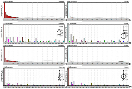
Figure 2.
Misorientation distribution frequency of intercrystalline boundaries (a,b,e,f) and frequency of CSL boundaries (c,d,g,h) for Al (a,c,e,g) and for Cu (b,d,f,h) in the deformed state (a–d) and in the partially recrystallized state (e–h). The areas of circles in (c,d,g,h) show the frequencies of the rotation axes for the CSL boundaries.

Table 1.
Fraction of CSL boundaries and Σ3 in the total number of intercrystalline boundaries.
One can infer that CSL boundaries close to Σ3 (Σ25b (51.68°, <331>), Σ33c (58.98°, <110>), Σ41c (55.88°, <110>), and Σ45c (53.13°, <221>)) are a result of the scattering of primary twin stable deformation orientations during numerous drawing stages [44]. Thus, grains maximally disoriented relative to each other have axes parallel to the deformation direction (DD): <111> and <100>, specifically the Σ3 boundary and those close to it.
CSL boundaries with rotation axes <111> (Σ7, Σ13b, Σ19b, Σ21a, Σ37c, Σ39a) and <100> (Σ5) are formed due to the scattering of primary texture components around the deformation axis.
The deviation from twin misorientation towards misorientations with higher sigma values obviously occurs as a result of the accumulation of dislocation density near grain boundaries during cold-drawing.
Recrystallization texture mostly repeats deformation texture by component composition in both Al and Cu (Figure 1k,l,o,p). At the same time, recrystallization textures of Al and Cu significantly differ from each other in the strongest components (Figure 1m,n,q,r).
The recrystallization texture of Al is characterized by two strong components close to {023}<232> (Figure 1m,i,s) and two close to {113}<121> (Figure 1n,j,t). These components correspond to the edges of the areas of the main deformation components scattering.
Strong components in the recrystallization texture of Cu are {110}<001> and {100}<001>. The <100> axis of {100}<001> orientation deviates from DD at about 13°, which can be clearly seen from the analysis of ODFs in the form of separate poles (Figure 1p). Moreover, weak recrystallization components in Cu have almost precise twinning orientations to {110}<001> and {100}<001> [10,35,49].
Thus, in both Al and Cu, recrystallization caused the growth of grains with orientations that are present in small quantities in the deformation texture and correspond to the edges of areas of the main deformation components scattering (Figure 1). It was often observed that the “carriers” of recrystallization components were near-boundary crystallites located inside the deformed grains of one of the main deformation components [10,35,50].
The analysis of the distribution maps of special misorientations (CSL) has shown that the grains growing during recrystallization (R) most often have special misorientations Σ25b (51.68°, <331>), Σ33c (58.98°, <110>), Σ41c (55.88°, <110>), and Σ45c (53.13°, <221>) with one of the main components of deformation (Figure 2g,h and Figure 3). All these misorientations are observed both individually and can transform one into the other (Figure 3a,c,e,g). These misorientations are observed both between deformed grains and between growing recrystallized and deformed grains [10,35]. At the same time, it was observed [36] that recrystallization nuclei in Al were formed in the deformed grains separated by boundaries close to Σ3.
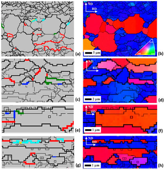
Figure 3.
CSL boundaries marked in partially recrystallized samples: (a–d)—Al; (e–h)—Cu; (a,c,e,g)—coincidence site lattice (CSL) boundaries maps (Σ3—red; Σ25b—green; Σ33c—yellow; Σ41c—azure; Σ45c—blue); (b,d,f,h)—RD (DD) inverse pole figure colored maps.
It is important to note that in both deformed and partially recrystallized states, most of the high-angle grain boundaries are in the range of misorientation angles of 52–60° (Figure 2a,b,e,f).
Vector analysis based on the results of orientation microscopy (EBSD) in the form of Euler angles showed the following: A rotation at an angle of approximately 52–70° around one of the crystallographic axes <772> describes the misorientation between the growing recrystallized grain and the deformed matrix most exactly. This misorientation is intermediate between all of the above CSL misorientations observed experimentally. This misorientation does not have an exact, ideally disoriented CSL boundary. Figure 4 shows the distribution of misorientation axes in a standard inverse pole figure, which also demonstrates the evolution of the main misorientations during recrystallization. For partially recrystallized samples, the misorientations with axes close to <331>-<553> share a significant fraction in the range of rotation angles of 60–70° (Figure 4b,e).
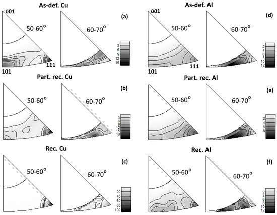
Figure 4.
Standard stereographic triangle in which the misorientation axes are distributed for deformed (a,d), partially recrystallized (b,e), and recrystallized (c,f) Cu (a–c) and Al (d–f).
For the deformation texture components, the CSL Σ3 misorientation is observed either between the main paired components: (011) [] and (110) [], (112) [] and () [], or between components of the following types: {112}<111> and {100}<001>; {110}<111> and {110}<001> (Figure 3b,d,f,h). In the latter two cases, the misorientation is not accurate but only close to Σ3 and deflects from it at 21.8° and 15.8°, respectively.
In the case of Cu, which has a tendency to twinning, almost precise Σ3 orientations form inside the grains during the deformation. The work [32] pointed out that components with axis <111> parallel to DD are more prone to twinning. The twins, which develop during deformation, have an axis parallel to DD and close to <100>.
It has been demonstrated in our previous work [10] that only grains with components {uuw}<100> with all their inherent twins, which result in components {uuw}<111>, grow during primary recrystallization in the central area of the copper wire.
Thus, differences in recrystallization textures of aluminum and copper can be explained by the high mobility of the same special boundary but different sites of nuclei formation (Figure 5). In aluminum, the recrystallization nuclei are formed at the boundary close to CSL Σ3 that separates grains with stable deformation components. A crystallite (block) in one of the neighboring deformed grains can serve as a nucleus if it acquires special misorientation with the neighboring grain, which is characterized by rotation about the <772>-axis at angles in the range of 52–70° (Figure 5a).
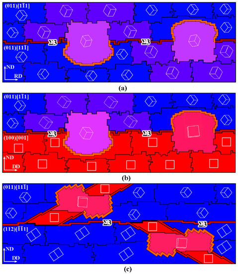
Figure 5.
Schematic mechanisms for the formation of primary recrystallization nuclei due to the appearance of a mobile crystallographically conditioned high-angle grain boundary: (a) most likely in Al; (b) possible in Cu and Al; (c) most likely in Cu.
In copper, a similar mechanism is also possible (Figure 5b). However, more often in copper, the primary recrystallization nucleus is a block (crystallite) from the deformation twin, in which the special misorientation Ʃ3 has been transformed into the special misorientation mentioned above (Figure 5c). Apparently, the formation of this block is easier in the area of deformation adjacent to the high-angle boundary. It is obvious that nucleation in Cu according to such a mechanism should occur significantly more frequently because of its propensity for deformation twinning. This can explain the relatively smaller size of the primary recrystallized grains in Cu in comparison with Al relative to the size of the initially deformed grains in both metals.
The newly growing grain has a misorientation that is close to twin-like with the deformed matrix region into which it grows. Special HAGBs, close to Σ25b, Σ33c, Σ41c, and Σ45c, likely have enhanced mobility, aiming towards their nearest structural state with minimal energy, i.e., the Σ3 CSL boundary. In this, the rotation axis is parallel to TD; rotations relative to other external coordinates are improbable. Therefore, the possibility of recrystallization orientation within the previously stable deformation orientation is much higher, presumably due to a more energetically favorable turn.
The results of this work raise the question of a relatively small number of possible boundary variants between crystal lattices of grains in metals that are present in the form of high-angle boundaries. These boundaries should have different mobility. The latter is necessary to explain deformations and structural transformations at the atomic scale. There are only two of them according to the obtained results: the almost fixed low-energy CSL Σ3 boundary (twin boundary) and the mobile boundary, approximately corresponding to the orientation: rotation about the <772>-axis at an angle of 52–70°, which cannot be precisely defined among CSL misorientation boundaries). The results of the current work correlate well with the results from [51] obtained using TEM electron diffraction.
The results of this work draw an analogy between the processes that take place during phase transformations and structural transformations (recrystallization) in metals and alloys. For both types of phase transformations, including shear (martensitic) transformations and diffusion-controlled transformations, the orientation relationship is obeyed for the crystal lattices of the original and resulting phases, which is expressed in the parallelism of closed-packed planes and directions. This strict relationship results in the nucleation of the resulting phase on the appropriate grain boundaries serving as a substrate and, therefore, determining the crystallographic texture formed in the process of phase transformation [25,26,52]. Special misorientations serve as orientation relationships in the case of structural transformations, and the special boundaries play the role of substrate.
4. Conclusions
Reorientation of the crystal lattice during deformation leads to the formation of CSL boundaries with a rotation axis close to <110>. Specifically, these misorientations that arise in the early stages of deformation and persist throughout the entire deformation process will be responsible for the nucleation process during recrystallization.
- Equivalent local deformation textures of Al and Cu are transformed into substantially different recrystallization textures.
- Recrystallization nuclei in Al are formed in most cases between the deformed grains at high-angle boundaries close to CSL boundaries Σ3. The recrystallization nuclei in Cu are formed at the twin boundaries (CSL Σ3) inside the deformed grains.
- It is supposed that recrystallization nuclei in both Cu and Al are crystallites having a high-angle special (crystallographically ordered) boundary with a deformed matrix, approximately which can be equally transformed by rotation about the <772>-axis at an angle in the range of 52–70°.
Author Contributions
Conceptualization, M.L.L. and M.A.Z.; methodology, M.A.Z. and A.A.R.; data curation, M.A.Z. and M.L.L.; validation, P.L.R. and M.S.K.; investigation, M.S.K., V.I.P. and M.A.Z.; resources, V.I.P. and M.S.K.; visualization, M.A.Z. and P.L.R.; supervision, M.L.L.; Writing—original draft, M.A.Z. and P.L.R.; Writing—review and editing, M.L.L. and A.A.R. All authors have read and agreed to the published version of the manuscript.
Funding
This research was funded by the Ministry of Science and Higher Education of the Russian Federation (Ural Federal University Program of Development within the Priority-2030 Program).
Institutional Review Board Statement
Not applicable.
Informed Consent Statement
Not applicable.
Data Availability Statement
The data presented in this study are available on request from the corresponding author.
Conflicts of Interest
The authors declare no conflict of interest.
References
- Wassermann, G.; Grewen, J. Texturen Metallischer Werkstoffe; Springer: Berlin, Germany, 1962. [Google Scholar]
- Sidor, J. Effect of Hot Band on Texture Evolution and Plastic Anisotropy in Aluminium Alloys. Metals 2021, 11, 1310. [Google Scholar] [CrossRef]
- Faurie, D.; Renault, P.-O.; Le Bourhis, E.; Goudeau, P. Study of Texture Effect on Elastic Properties of Au Thin Films by X-ray Diffraction and In Situ Tensile Testing. Acta Mater. 2006, 54, 4503–4513. [Google Scholar] [CrossRef]
- Hara, T.; Shinohara, Y.; Asahi, H.; Terada, Y. Effects of Microstructure and Texture on DWTT Properties for High Strength Line Pipe Steels. In Proceedings of the 2006 International Pipeline Conference, Calgary, AB, Canada, 25–29 September 2006; American Society of Mechanical Engineers Digital Collection, 2 October 2008. pp. 245–250. [Google Scholar]
- Rajan, K.; Petkie, R. Microtexture and Anisotropy in Wire Drawn Copper. Mater. Sci. Eng. A 1998, 257, 185–197. [Google Scholar] [CrossRef]
- Naghdy, S.; Pirgazi, H.; Verleysen, P.; Petrov, R.; Kestens, L. Morphological and Crystallographic Anisotropy of Severely Deformed Commercially Pure Aluminium by Three-Dimensional Electron Backscatter Diffraction. J. Appl. Crystallogr. 2017, 50, 1512–1523. [Google Scholar] [CrossRef]
- Rollett, A.; Humphreys, F.; Rohrer, G.S.; Hatherly, M. Recrystallization and Related Annealing Phenomena, 2nd ed.; Elsevier Ltd.: Amsterdam, The Netherlands, 2004; ISBN 978-0-08-044164-1. [Google Scholar]
- Suwas, S.; Ray, R.K. Crystallographic Texture of Materials; Engineering Materials and Processes; Springer: London, UK, 2014; ISBN 978-1-4471-6313-8. [Google Scholar]
- Figueiredo, N.C.; de Oliveira, C.A.S.; Masoumi, M.; de Abreu, H.F.G. Microstructural Variations at Different Distance from the Surface in Forged 18 Ni C300 Maraging Steel. J. Mater. Res. Technol. 2019, 8, 284–291. [Google Scholar] [CrossRef]
- Zorina, M.A.; Lobanov, M.L.; Makarova, E.A.; Rusakov, G.M. Primary Recrystallization Texture in FCC-Metal with Low Packing Defect Energy. Met. Sci. Heat Treat. 2018, 60, 329–336. [Google Scholar] [CrossRef]
- Burbery, N.J.; Das, R.; Ferguson, W.G. The Observation of Structural Multiplicity in Σ5(310) Grain Boundaries in FCC Metals. Mater. Lett. 2015, 158, 413–415. [Google Scholar] [CrossRef]
- Gottstein, G. Physical Foundation of Materials Science; Springer: Berlin/Heidelberg, Germany, 2004; ISBN 3-540-40139-3. [Google Scholar]
- Taylor, G.I. Plastic Strain in Metals. J. Inst. Met. 1938, 62, 307–324. [Google Scholar]
- Bishop, J.F.W. A Theory of the Tensile and Compressive Textures of Face-Centred Cubic Metals. J. Mech. Phys. Solids 1955, 3, 130–142. [Google Scholar] [CrossRef]
- Hölscher, M.; Raabe, D.; Lücke, K. Relationship between Rolling Textures and Shear Textures in f.c.c. and b.c.c. Metals. Acta Metall. Mater. 1994, 42, 879–886. [Google Scholar] [CrossRef]
- Narayanan, K.R.; Sridhar, I.; Subbiah, S. Experimental and Numerical Investigations of the Texture Evolution in Copper Wire Drawing. Appl. Phys. A 2012, 107, 485–495. [Google Scholar] [CrossRef]
- Masui, H. Simulation for f.c.c. Deformation Texture by Modified Pencil Glide Theory. Acta Mater. 1999, 47, 4283–4298. [Google Scholar] [CrossRef]
- Huang, S.; Zhang, S.; Li, D.; Peng, Y. Simulation of Texture Evolution during Plastic Deformation of FCC, BCC and HCP Structured Crystals with Crystal Plasticity Based Finite Element Method. Trans. Nonferrous Met. Soc. China 2011, 21, 1817–1825. [Google Scholar] [CrossRef]
- Sidor, J.J.; Petrov, R.H.; Xie, Q.; Van Houtte, P.; Kestens, L.A.I. Evaluation of Crystallographic Changes and Plastic Strain Ratio in Al Alloys. Mater. Sci. Technol. 2017, 33, 667–677. [Google Scholar] [CrossRef]
- Sidor, J.J.; Petrov, R.H.; Kestens, L.A.I. Modeling the Crystallographic Texture Changes in Aluminum Alloys during Recrystallization. Acta Mater. 2011, 59, 5735–5748. [Google Scholar] [CrossRef]
- Sidor, J.; Kestens, L. Analytical Description of Rolling Textures in Face-Centred-Cubic Metals. Scr. Mater. 2013, 68, 273–276. [Google Scholar] [CrossRef]
- Priester, L. Grain Boundaries; Springer Series in Materials Science; Springer: Dordrecht, The Netherlands, 2013; Volume 172, ISBN 978-94-007-4968-9. [Google Scholar]
- Hurley, P.J.; Humphreys, F.J. Modelling the Recrystallization of Single-Phase Aluminium. Acta Mater. 2003, 51, 3779–3793. [Google Scholar] [CrossRef]
- Chalapathi, D.; Palla, S.; Kanjarla, A. A Crystal Plasticity Investigation on the Influence of Orientation Relationships on Texture Evolution during Rolling in Fcc/Bcc Two Phase Materials. Mater. Today Commun. 2022, 31, 103300. [Google Scholar] [CrossRef]
- Kestens, L.A.I.; Nguyen-Minh, T.; Petrov, R.H. The Role of Parent Phase Topology in Double Young–Kurdjumow–Sachs Variant Selection during Phase Transformation in Low-Carbon Steels. Metals 2022, 12, 939. [Google Scholar] [CrossRef]
- Tomida, T.; Wakita, M. Transformation Texture in Hot-Rolled Steel Sheets and Its Quantitative Prediction. ISIJ Int. 2012, 52, 601–609. [Google Scholar] [CrossRef][Green Version]
- Vazdirvanidis, A.; Rikos, A.; Toulfatzis, A.I.; Pantazopoulos, G.A. Electron Backscatter Diffraction (EBSD) Analysis of Machinable Lead-Free Brass Alloys: Connecting Texture with Fracture. Metals 2022, 12, 569. [Google Scholar] [CrossRef]
- Naghdy, S.; Percq, L.; Serret, R.; Petrov, R.; Hertelé, S.; Kestens, L.; Verleysen, P. Microstructural Evolution Study of Severely Deformed Commercial Aluminum by Transmission Kikuchi Diffraction. Mater. Sci. Technol. 2016, 33, 678–687. [Google Scholar] [CrossRef]
- Verma, S.; Kamalakshi, G.; Gururajan, M.; Pant, P. Misorientation Development at Σ3 Boundaries in Pure Copper: Experiments and MD Simulations. Metall. Mater. Trans. A 2023, 54, 2656–2669. [Google Scholar] [CrossRef]
- Dolzhenko, P.; Tikhonova, M.; Odnobokova, M.; Kaibyshev, R.; Belyakov, A. On Grain Boundary Engineering for a 316L Austenitic Stainless Steel. Metals 2022, 12, 2185. [Google Scholar] [CrossRef]
- Field, D.P.; Bradford, L.T.; Nowell, M.M.; Lillo, T.M. The Role of Annealing Twins during Recrystallization of Cu. Acta Mater. 2007, 55, 4233–4241. [Google Scholar] [CrossRef]
- Yuan, L.; Gou, F.; Sun, D.; Li, Z.; Xue, Y. The Effects of Cold Rolling and Annealing on the Microstructure Evolution of Ordered C-2000 Alloy during Metallic Wire Preparation. Metals 2023, 13, 651. [Google Scholar] [CrossRef]
- Li, X.; Guan, X.; Jia, Z.; Chen, P.; Fan, C.; Shi, F. Twin-Related Grain Boundary Engineering and Its Influence on Mechanical Properties of Face-Centered Cubic Metals: A Review. Metals 2023, 13, 155. [Google Scholar] [CrossRef]
- Lin, F.; Zhang, Y.; Godfrey, A.; Jensen, D. Twinning during Recrystallization and Its Correlation with the Deformation Microstructure. Scr. Mater. 2022, 219, 114852. [Google Scholar] [CrossRef]
- Zorina, M.A.; Karabanalov, M.S.; Loginov, Y.N.; Lobanov, M.L. Crystallographic Laws of Formation of Recrystallization Texture in a Copper Capillary Tube. Met. Sci. Heat Treat. 2022, 64, 3–8. [Google Scholar] [CrossRef]
- Reznik, P.L.; Redikultsev, A.A.; Lobanov, M.L. Effect of Special Misorientations—Crystallographic Ordered Boundaries in Recrystallization in Aluminium Alloy of Al-Si-Mg System. IOP Conf. Ser. Mater. Sci. Eng. 2020, 969, 012012. [Google Scholar] [CrossRef]
- Kumano, T.; Haratani, T.; Ushigami, Y. The Relationship between Primary and Secondary Recrystallization Texture of Grain Oriented Silicon Steel. ISIJ Int. 2002, 42, 440–448. [Google Scholar] [CrossRef]
- Shimizu, R.; Harase, J.; Dingley, D. Prediction of Secondary Recrystallization Texture in Fe3% Si by Three-Dimensional Texture Analysis. Acta Metall. Mater. 1990, 38, 973–978. [Google Scholar] [CrossRef]
- Kataoka, T.; Atsumi, H.; Yasuda, M.; Morishige, N.; Murakami, K. Effects of Grain Boundary Characteristics on Secondary Recrystallization Textures in Fe–Si Alloy. ISIJ Int. 2020, 61, 960–966. [Google Scholar] [CrossRef]
- Panzarino, J.F.; Pan, Z.; Rupert, T.J. Plasticity-Induced Restructuring of a Nanocrystalline Grain Boundary Network. Acta Mater. 2016, 120, 1–13. [Google Scholar] [CrossRef]
- Schuman, C.; Philippe, M.J.; Esling, C.; Jallon, M.; Hergesheimer, M.; Lefort, A. Texture Evolution during the Drawing of an Interstitial-Free Low Carbon Steel. Mater. Sci. Forum 1994, 157–162, 847–852. [Google Scholar] [CrossRef]
- Bunge, H.-J. Texture Analysis in Materials Science. Mathematical Methods; Elsevier Ltd.: Amsterdam, The Netherlands, 1969; ISBN 978-0-408-10642-9. [Google Scholar]
- Montesin, T.; Heizmann, J.J. Evolution of Crystallographic Texture in Thin Wires. J. Appl. Crystallogr. 1992, 25, 665–673. [Google Scholar] [CrossRef]
- Zorina, M.A.; Karabanalov, M.S.; Stepanov, S.I.; Demakov, S.L.; Loginov, Y.N.; Lobanov, M.L. Fiber vs Rolling Texture: Stress State Dependence for Cold-Drawn Wire. Metall. Mater. Trans. A 2018, 49, 427–433. [Google Scholar] [CrossRef]
- Christian, J.W. The Theory of Transformations in Metals and Alloys; Pergamon: İzmir, Turkey, 2002; ISBN 0-08-044019-3. [Google Scholar]
- Holm, E.A.; Olmsted, D.L.; Foiles, S.M. Comparing Grain Boundary Energies in Face-Centered Cubic Metals: Al, Au, Cu and Ni. Scr. Mater. 2010, 63, 905–908. [Google Scholar] [CrossRef]
- Luo, X.M.; Song, Z.M.; Li, M.L.; Wang, Q.; Zhang, G.P. Microstructural Evolution and Service Performance of Cold-Drawn Pure Aluminum Conductor Wires. J. Mater. Sci. Technol. 2016, 33, 1039–1043. [Google Scholar] [CrossRef]
- Bulatov, V.V.; Reed, B.W.; Kumar, M. Grain Boundary Energy Function for Fcc Metals. Acta Mater. 2014, 65, 161–175. [Google Scholar] [CrossRef]
- Peng, X.; Song, K.; Zhou, Y.; Huang, T.; Liu, H.; Hua, Y.; Yang, J.; Wang, G. Influence of P Content on Microstructure and Texture Evolution of the Oxygen-Free Copper. Metals 2022, 12, 1622. [Google Scholar] [CrossRef]
- Wang, X.; Xiong, W.; Zheng, Y.; Zhang, J. The Correlation between Texture Evolution and Recrystallization Behavior during Rheologic Forming of 2195 Al–Li Alloy Cylindric Shell. Metals 2023, 13, 853. [Google Scholar] [CrossRef]
- Haasen, P. How Are New Orientations Generated during Primary Recrystallization? Metall. Trans. A 1993, 24, 1001–1015. [Google Scholar] [CrossRef]
- Landheer, H.; Offerman, S.E.; Petrov, R.H.; Kestens, L.A.I. The Role of Crystal Misorientations during Solid-State Nucleation of Ferrite in Austenite. Acta Mater. 2009, 57, 1486–1496. [Google Scholar] [CrossRef]


Disclaimer/Publisher’s Note: The statements, opinions and data contained in all publications are solely those of the individual author(s) and contributor(s) and not of MDPI and/or the editor(s). MDPI and/or the editor(s) disclaim responsibility for any injury to people or property resulting from any ideas, methods, instructions or products referred to in the content. |
© 2023 by the authors. Licensee MDPI, Basel, Switzerland. This article is an open access article distributed under the terms and conditions of the Creative Commons Attribution (CC BY) license (https://creativecommons.org/licenses/by/4.0/).