Abstract
In order to ensure environmentally friendly mobility, electric drives are increasingly being used. As a result, the number of used lithium-ion batteries has been rising steadily for years. To ensure a closed recycling loop, these batteries must be recycled in an energy- and raw material-efficient manner. For this purpose, hydrometallurgical processes are combined with mechanical pre-treatment, including disintegration by mills, crushers and/or shears. Alternatively, electrohydraulic fragmentation (EHF) is also of great interest, as it is considered to have a selective fragmentation effect. For a better comparison, different application scenarios of EHF with other methods of mechanical process engineering for the treatment of lithium-ion batteries are investigated in the present study.
1. Level of Knowledge
Electrohydraulic fragmentation (EHF) is based on the generation of shock waves in a reactor filled with a dielectric fluid [1,2]. There are at least two electrodes in the reactor, of which one is the reactor itself, that induce a high-voltage discharge. The plasma channel of the corresponding arc generates a short-wave first shock wave, and the cavitation that occurs generates a second shock wave. Both shock waves represent a homogeneously distributed energy input in the reactor.
The more incompressible the fluid, the higher the mechanical load on the test material during EHF [2]. Therefore, comminution based on the electrohydraulic effect is, according to Rumpf [3], one of the stress types where there is no solid surface of the comminution apparatus involved. Especially at material interfaces of the stressed product, e.g., grain boundaries or material transitions in composites, the waves are reflected and scattered, whereby local stresses are built up and, ultimately, fracture events are triggered in the interfaces. This mechanism is described in the literature as predestined for the disintegration of material composites [1,4,5,6,7].
In addition to this comparatively young technology for liberation, there is a large variety of machines that can disintegrate material composites with the aid of pressure, cutting, and/or bending stresses. These processes belong to the group of stresses with one or two solid surfaces [3]. The corresponding apparatus concepts have in common that the stress energy is locally applied to the material, mostly in a punctiform or planar manner [8]. In the case of pressure and impact stress, fracture phenomena occur, especially in the case of brittle material, which, among other things, produces a lot of fine grain [9]. Ductile materials can be comminuted better with cutting or shearing stress, whereby fracture occurs due to the often-linear energy input at the knife edges. For the disintegration of lithium-ion batteries, a complex stress with tensile, bending, and tearing stress should therefore be selected. An overview of existing recycling routes, which also include mechanical processes, has been summarised by Werner et al. [10].
This paper examines applications in which EHF could supplement conventional technologies or even replace them entirely. The evaluation criterion is first and foremost the degree of liberation of the valuable materials and the energy input required for this.
1.1. Lithium-Ion Batteries
Lithium-ion batteries (LIB) are constructed like typical electrochemical storage systems [11]. Simplified, there are two electrodes, an anode and cathode, between which ions are exchanged so that an electric current flows. In LIB, graphite serves as the negative electrode material (anode) and a metal oxide as the positive electrode material (also called active material, or cathode). However, research is constantly being done on new materials for coating the electrodes in order to improve performance or to have to use less critical materials [12,13,14]. In most cases, the electrodes are encased in a metallic housing to protect them from the environment, as well as to prevent the leakage of hazardous compounds. There are different geometric shapes of batteries, with three main types used in electric vehicles: cylindrical cells, pouch cells, and prismatic cells [15].
To ensure sufficient geometric stability of the anode and cathode, they are coated to a metallic current collector foil consisting of copper and aluminium, respectively [11]. A porous separator made of plastic prevents direct contact between the electrodes and at the same time enables ion exchange. A lithium salt, the so-called conducting salt, which is dissolved in a mixture of organic solvents, ensures this charge exchange by means of freely moving ions. Solvent and lithium salt together form the electrolyte.
Due to the compact design of modern LIBs, a large part of the electrolyte is located in the pores of the separator and the porosity of the coatings of the two metallic conductor foils. When the battery cell, which is closed during the use phase, is opened, e.g., during recycling, the solvents begin to evaporate. The conductive salt crystallises or decomposes when it comes in contact with air humidity. Therefore, the salt or its degradation products can be found mainly in both the coating and the separator during and after mechanical processing [16].
1.2. Liberation of Battery Cell Components
The principle of EHF is described as very efficient, especially in the processing of high-quality electronic devices [6,7]. Other studies show that only a small proportion of the energy used flows into the comminution, as a large part of the energy is dissipated in the process medium [17]. Here, the fundamental principle of EHF must be taken into account, which is based on the creation of a plasma channel that inevitably not only triggers shock waves, but also heats the process medium.
For mineral raw materials, concrete, and other composites, there are feasibility studies on liberation using EHF [4,6,18,19,20,21]. The extent to which EHF is suitable for the processing of lithium-ion batteries has also been investigated [7,22,23].
1.2.1. Delamination Using EHF
Promising preliminary tests have been documented by the manufacturers of EHF technology for sorted production waste from battery cell production. The investigations focused on the single-variety recovery of coating materials (cathode) and their return to the production process. For this purpose, the active material broken down by EHF could be separated from the aluminium foil by subsequent classification. Since the composition of the active material was known and the starting material was pure, the active material could then be fed into the production process without further cleaning steps. To apply this procedure to the recycling of manufactured battery cells, they would have to be dismantled down to the electrode level. Manual dismantling of the electrodes is not economically feasible, as it is both time-consuming and labour-intensive, and also places high demands on personal safety at work. With the increasing number of end-of-life batteries, alternatives on a technical scale are inevitable [24,25,26].
A method that is already common in other industries would be to automate this step, thus creating the prerequisite for achieving the required throughput. Designing a system for this task requires detailed conception and planning and a non-negligible investment. The problem, however, is the large number of cell types and superstructures available on the market, which cannot be processed by a universal automated dismantling line. This means that a safe and fast amortization of such a system is not possible with the current prerequisites. Werner et al. [10] have provided an overview of current studies.
In addition to the economic provision of suitable feedstock, there are many parameters influencing the process result in EHF. This effect can be noticed when analysing the results of decoating tests, where the data range from a maximum of 60% to at least 95% [17,27]. Among other things, the reactor size and shape play a role. The degree of filling, the pulse energy and frequency, the shape and number of electrodes used, and the test material itself can also have a major influence on the result. Less obvious parameters such as the field strength ratio at the electrode arrangement, the conductivity of the reactor sliquid, the current transient ratio, and the system resistance also have a decisive influence on the process result and efficiency of the system [28].
1.2.2. Liberation of Valuables Using High Voltage Liberation
Fundamental studies on the use of EHF for complete end-of-life batteries can hardly be found in the literature. Often, only unmixed anode or cathode foils from production rejects or manual dismantling are used, where EHF is applied for decoating (Section 1.2.1). Experiments on the disintegration of whole battery cells mostly refer to pouch or small round cells [17,27,29]. Results for the processing of prismatic cells from the automotive industry cannot be found. Corresponding tests were carried out as part of the EU/KIC project AutoBatRec2020.
Compared to mineral processing, comparatively high-stress energies of approximately 1.8 kWh/kg are required for the disintegration of type 18,650 battery cells with the help of EHF [7,29]. Tests with pre-damaged cells show better results in some cases [27]. No information is given on the energy required for pre-damage or the amount of energy saved. No degrees of decoating are given for these tests either, which is why no conclusion can be drawn about the process result. However, since it is a mixture of the coating materials of both electrodes and these have 9% metallic impurities [7], this rules out direct reuse in electrode production. For battery raw materials such as graphite, a very high purity of 99.9% is required [30].
Similar results can also be observed using electrodynamic fragmentation (EDF) [31]. Here, the specific energy required to open cells of type 18,650 (with steel housing) is in a similar range to that of EHF. The differences between the two processes are well documented for the crushing of rocks [32,33]. EDF differs from EHF by a higher voltage and a higher speed at which the pulse builds up. Furthermore, the pulse is usually conducted through the material and not through the liquid surrounding the sample, as is the case with EHF. When discharged by a dielectric fluid, as in EHF, the surrounding particles are hit by a shock wave and thus they are stressed to pressure. If the discharge takes place through the solid itself, tensile forces are initiated, especially along phase boundaries. Furthermore, this does not apply to all discharges, as the system changes with each pulse. This means that discharges can also occur through the solids in the EHF and vice versa. A direct comparison regarding the advantages for the recycling of LIBs could not be found in the literature research, except for a similar energy consumption. Due to the material properties and process differences, a different throughput in favour of EHF is conceivable.
1.2.3. Liberation of Valuables Using Mechanical Processes
In contrast to disassembly or the use of EHF, there is classic mechanical liberation through comminution. The type and intensity of this must be adapted to the feed material in such a way that sufficient liberation of the components is achieved in order to separate them from each other in subsequent sorting processes.
Single-shaft and multi-shaft shredders with a discharge grate have proven to be suitable machine technology for the disintegration of LIB cells and modules [34,35]. A suitable machine for the disintegration of LIBs is, for example, a universal granulator (company Andritz MeWa) [36]. The battery cells are crushed by shearing and cutting stresses between the rotor and stator. The retention time and product particle size can be influenced by the use of different outlet grid sizes (10–40 mm), which in turn influences liberation.
This procedure separates the cell components from each other and breaks down the wound electrode and foil composites. In the process, part of the electrode coating is already removed from the conductor foils and can be separated from the comminuted product by classification at a desired sieve mesh width. However, if the decoating is too intensive, there is a risk of producing fine metallic particles, particularly from the conductor foils, which will increase the amount of impurities within the active material [7]. During conventional mechanical decoating, the conductive salt, electrolyte, separator, housing, or anode components can become fine-grained, thus being transferred into the black mass fraction, in addition to the active material, during sieving. In this case, those impurities must be separated from the coating material [36,37].
2. Methodology of the Study
According to the literature [22], the disintegration of intact prismatic LIB battery cells from electromobility by EHF appears to be uneconomical due to the very high energy input required. Therefore, a combination of classic mechanical pre-treatment and post-treatment by EHF was considered in the present study [27]. The pre-treatment acts in the sense of coarse disintegration of the battery cells and the post-treatment decoats the conductor foils. This corresponds to an initial mechanical pre-treatment, which comes closest to later industrial practice.
For this purpose, the disintegration of cells was investigated in a first series of tests (test series 1) and the decoating of an electrode foil mixture in a second series of tests (test series 2). To create a reference sample, two battery cell types were manually disassembled and characterised. The main focus for both test series was on the decoating of the conductor foils.
After the samples had been stressed by EHF, the entire reactor content was sieved at 500 µm in both test series. The sieve residue comprised coarser electrode pieces, the sieve passage black mass, and process water. The black mass was then dewatered with the aid of vacuum filtration and dried for 24 h at 80 °C. Both the black mass and the resulting process water were analysed using ICP-OES.
2.1. Material Used
Two different types of LIB cells were used for the tests (Figure 1 and Table 1). They both originate from the automotive sector and are prismatic in their outer shape. The main differences lie in their geometric dimensions. The two types were chosen due to having the most common cathode chemistry NMC used for electric cars [15]. However, there is a wide range of size and design of LIB cells on the market. For this reason, two different cell sizes were used for the study in order to show any effects that could occur in recycling.
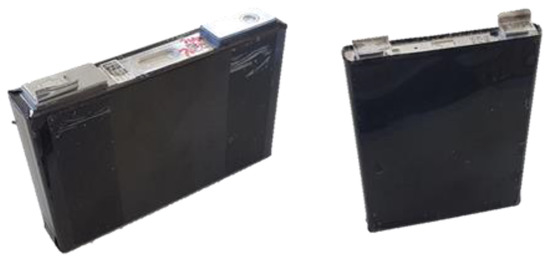
Figure 1.
Battery cell type 1 (left) und type 2 (right).

Table 1.
Types of lithium-ion battery cells studied.
2.2. Liberation of Pre-Shredded Cells Using EHF
It is known from the literature (see Section 1.2.2) that undamaged round cells require a lot of energy to break open the cell housing with the help of EHF. In the first series of tests, the battery cells of type 1 and 2 were therefore pre-shredded by a slowly rotating small-scale axial gap rotary shear at a circumferential speed of the blades of 0.4 m/s [38]. This procedure was intended to provide an initial surface for the shock waves of EHF to attack and thus achieve the disintegration and, if possible, the decoating of the electrode foils at energy inputs that are low compared to the disintegration of intact battery cells.
The tool width of the rotor shear was 40 mm, and the distance between the tools was negligibly small (<0.1 mm). With this pre-shredding, the cell housing was broken open without achieving the complete liberation of all components (Figure 2).
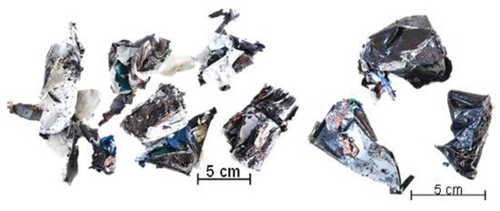
Figure 2.
Pre-shredded battery cell type 1 (left) and type 2 (right).
Subsequently, the battery cells were further stressed by EHF in a batch test. Demineralised water was used as the non-leachable liquid. The test parameters are summarised in Table 2. Figure 3 shows the schematic sequence of the test series.
Table 2.
Overview of the EHF test parameters.
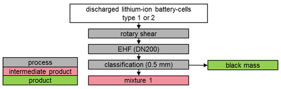
Figure 3.
Schematic illustration of test series 1.
2.3. Decoating of an Electrode Fraction by Means of EHF
Test series 2 is divided into two sub-tests. In test series 2A, the battery cells of type 1 were pre-shredded in the rotor shear as described above, then further comminuted and liberated in a granulator (UG 300, Figure 4) from MeWa Andritz at a 12, 20, 30, or 40 mm grate-hole size. By classifying the crushed product, a first black mass (Figure 5: black mass 1) was separated. In this case, the sieve mesh size was selected at 1 mm.
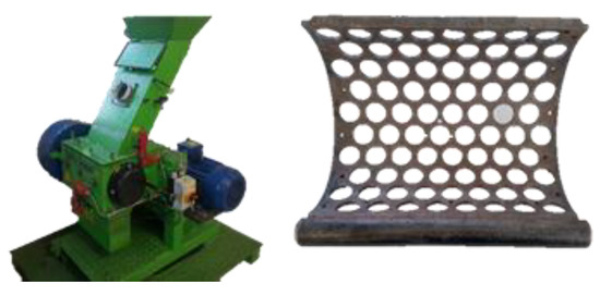
Figure 4.
Universal granulator UG 300 (left), and outlet grate (right).
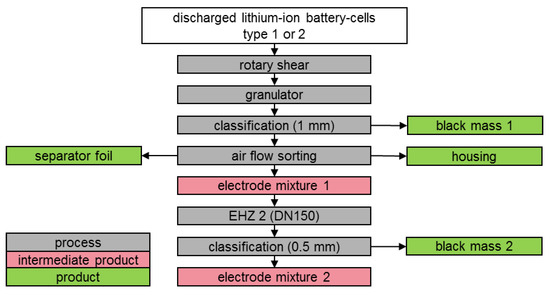
Figure 5.
Schematic illustration of test series 2.
With the sieve fraction of >1 mm, separator foils and cell housings were separated in a multi-stage sifting process using a zig-zag air-classifier. The remaining intermediate product consisted mainly of partially coated electrode foils. Figure 5 schematically illustrates the process of disintegration and subsequent separation of the electrode foil fraction. The experimental set-up is based on the procedure from [36].
The electrode foil mixture 1 produced in this way was then subjected to a batch test using EHF. The mass ratio between solid and fluid was set at 0.01 to 0.02 according to literature values [17] and prepared accordingly by means of sample division of the electrode mixture. Further parameters are shown in Table 2. The aim of this test series was to selectively decoat the electrodes in favour of the anode (Figure 5: black mass 2).
In order to investigate whether a complete decoating of both electrode foils is possible, a sample was pre-crushed to 20 mm in the granulator in test series 2B. Afterwards, the material was exposed to high-energy pulses followed by low-energy, high-frequency pulses.
2.4. Test Evaluation
To determine the chemical compositions, representative samples of the material were digested with aqua regia in a 24-h procedure. All components except the graphite and the polymeric binders were brought into solution. The graphite was filtered off and its mass determined. The solution was analysed with optical emission spectrometry ICP-OES (iCAP6300 duo, Thermo Fisher Scientific, Dreieich, Germany) for lithium, nickel, cobalt, manganese, phosphorus, aluminium, and copper. The ICP analysis provides values in mg/L for the elements mentioned. Then, the mass concentration was calculated using the sample weight and the volume of the aqua regia solution and is displayed in wt.-% (mgElement/mgBlackmass in %). The phosphorus content was used to stoichiometrically calculate the proportion of the conductive salt LiPF6. The proportions of the coating materials in the total weight of the battery cell were determined gravimetrically.
During mechanical processing, the coating materials accumulate in the fine fraction regardless of their origin from cathode or anode [36]. Due to its characteristic colour, this mixture is generally called black mass. The proportions of aluminium and copper determined by means of emission spectrometry result from the finest fragments of the conductor foils and, like the conductive salt, are regarded as impurities of the coating materials in the black mass.
Through manual disassembly and subsequent identical analysis, the masses of the coatings m0 on the anode and cathode, as well as their material compositions per battery cell in the initial state, were known. Based on this, the degree of decoating E was calculated using Equation (1) after analysing the black mass. This relates the coating material in the black mass mBM,B, which was removed by the mechanical stress, to the total coating material present.
In addition, conclusions about the selectivity of the decoating were drawn from the chemical analysis of the black mass and the enrichment ratio i was calculated using Equation (2). The enrichment ratio relates the valuable material yield RBM of the component in question (e.g., the coating material of the anode A) to the mass yield Rm in the black mass. The mass yield relates the mass mBM of the black mass product to the mass of the starting material m0. The material yield relates the mass of the coating material of the anode in the black mass mBM,A to that of the starting material m0,A.
If a value greater than 1 is reached for i, the corresponding component accumulates in the black mass. Values smaller than one correspond to a depletion. If the enrichment ratio of the cathode coating differs from that of the anode coating in the black mass, selective stripping is present.
The specific energy input of EHF was calculated according to Equation (3). The number of pulses n was multiplied by the input energy EI per pulse and divided by the input mass m of the sample.
3. Result
3.1. Liberation of Valuables by EHF
For the pre-shredding of the battery cells of type 1 (Figure 2), approx. 1.5 kWh/t of electrical energy was applied in the rotor shear. The subsequent stressing by EHF was carried out with high-energy pulses, which corresponds to a specific energy input of 17.2 kWh/t. The essential challenge here is that material that has already been opened up strongly changes the mixing state of the EHF reactor. In particular, electrode and separator foils that were freely movable in the process chamber either completely suppressed the discharge between the electrodes or strongly attenuated the shock waves. Furthermore, in this case, the overall mobility of the particles was restricted, which meant that some remained between the electrodes of the EHF for a significantly longer time and were thus more stressed than others. To counteract this, the experiment had to be interrupted regularly and the already digested material removed from the reactor.
Even with these measures, complete disintegration of the battery cells could not be achieved. Around 30 mass percent of the cell fragments were still present in the compound, which is why an optimization of the process parameters is inevitably necessary for such an application. This could include increasing the number of pulses and thus the power input during EHF. Alternatively, a more extensive mechanical pre-treatment can be envisaged as a process optimization. For example, narrower tools or limiting the maximum particle size of the intermediate product by means of a discharge grate with a defined hole size are possible options.
In this test, about 230 g dry weight could be found as black mass. This corresponds to a degree of decoating E of around 65% for the anode and around 48% for the cathode (Figure 6 and Figure 7, green line), which can be used as a reference value for the second series of tests Section 3.2). The enrichment ratio for the anode coating of 1.26 confirms literature data [16,27], according to which the anode can be preferentially decoated. The proportion of metallic impurities is around 3.2% (Figure 8).
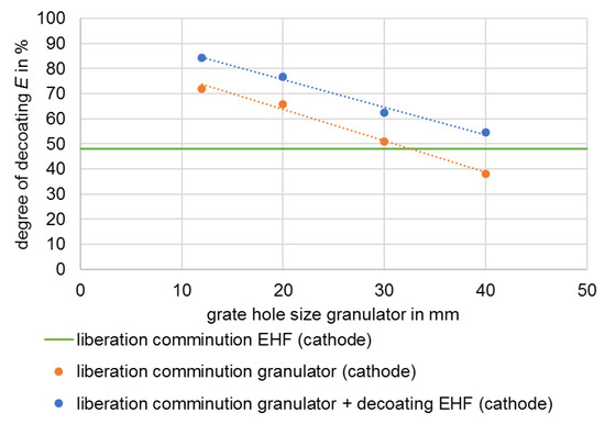
Figure 6.
Degree of decoating E of the cathode after different stresses.
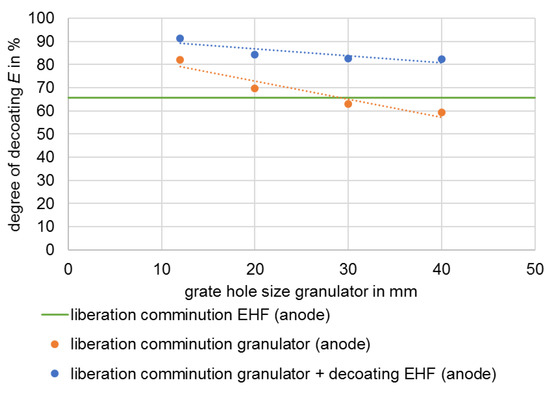
Figure 7.
Degree of decoating E of the anode after different stresses.
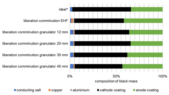
Figure 8.
Composition of the black masses of cell type 1 after liberation (ideal: composition of the coating materials in the intact battery cell). * Conducting salt content estimated according to [16].
For cell type 2, a test was carried out under comparable parameters. Since the battery cells of type 2 are significantly smaller, two pre-shredded cells were used as input. Furthermore, the total number of pulses was increased, resulting in a specific energy input of 107 kWh/t plus approximately 4.8 kWh/t for pre-shredding in the rotor shear. Despite the higher energy input, about 75% of the mass could not be liberated because the housing of the battery cells was deformed by the stress caused by EHF and thus the electrode windings were encapsulated. This effect can be attributed to the narrow design of these battery cells (Figure 1 and Figure 2).
By deforming the housing in EHF, the cut surfaces on the fragments that the rotor shear had produced were partially closed again, which reduced the effectiveness of the shock waves. In addition, the energy input by EHF would have to be increased or the pre-treatment process adjusted to achieve complete digestion. An investigation of the black mass was not carried out here, as a comparison with the other results is not expedient due to the incomplete digestion. Similar effects were also achieved in [27] for round cells with defined pre-damage.
Under the parameters considered, it was therefore not possible to achieve complete liberation of the battery cells for both cell types in the case of pre-shredding in the rotor shear with subsequent stressing by EHF. An even higher energy input through EHF would further contaminate the black mass fraction with metal and also reduce the yield of recyclable material in the metal fractions. At this point, it would be better to use a more intensive pre-stressing method and an adapted process control with EHF, or the use of alternative technologies for liberation.
3.2. Liberation of Valuables by Granulator
As a consequence of the results of disintegration by means of EHF from test series 1, disintegration by means of a granulator was selected (Section 1.2.3) and EHF was thus primarily used for decoating the electrode foils. A similar approach was also investigated in [27]. The size reduction was carried out with different discharge grates in the granulator, whereby the material with smaller grate opening widths is more strongly comminuted. The smaller openings increase the residence time of the material in the process chamber and the energy introduced, which at the same time leads to a higher decoating of the foils [16], which can be seen in Figure 6 and Figure 7.
In the example considered, specific energy values between 3.2 and 6.2 kWh/t were required for liberation of the valuable materials. Decoating degrees ranging from 59% to 82%, as well as from 38% to 72%, are achieved for the anode and cathode, respectively. The composition of the black mass after liberation also shows selectivity. The highest enrichment ratio i of 1.3 is achieved with a grate hole size of 40 mm and thus the lowest energy input. The metal content is on average 1.2%, and the conductive salt content around 3.6% (Figure 8).
The enrichment ratio with respect to the anode coating increases slightly along with the increase in grate hole size (Figure 9). At the same time, the diagram shows that at smaller grate hole sizes, and thus comparatively high energies, there is no enrichment in favour of the cathode coating. This confirms the statement from [16] that selective decoating is only possible at low-stress energies. Both, the metallic impurities and the proportion of conductive salt in the black mass are largely independent of the energy applied and thus of the decoating in the framework investigated. It follows that the conductive salt is uniformly present in the coating of the anode and cathode and is separated and discharged together with the latter.
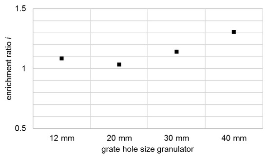
Figure 9.
Enrichment ratio i of the anode coating in the comminution product shown for different grate hole sizes of the granulator.
Compared to EHF (Section 3.1), the granulator with a 30 mm grate and an energy input of 4.3 kWh/t achieves similar decoating for both anode and cathode. At the same time, the proportion of metallic impurities in the black mass is only about one third as high at 0.9% (Figure 8). Furthermore, the proportion of conductive salt is higher because it cannot dissolve in the process medium due to the dry comminution.
3.3. Decoating of the Electrode Foil Fraction by EHF
Airflow sorting of the classified granulator product (Figure 5) produced an electrode foil mixture that could be further processed by EHF to separate still-adhering coatings from the conductor foils and thus produce a second black mass. The corresponding increase in the degree of decoating is shown in Figure 6 and Figure 7. In each of the trials, around 20 kWh/t of electrical energy was used for decoating.
For the cathode, it can be seen that, regardless of the degree of decoating of the input, a further approximate 12 percentage points of the original coating were removed on average. In contrast, 9 to 23 percentage points of the total coating were removed from the anode. This corresponds to about half of the coating remaining on the foils after disintegration in the granulator. This results in enrichment ratios i of up to approximately 1.65 for the anode, which indicates a preferential decoating of the anode.
Figure 10 shows the composition of the black mass delaminated by EHF in the second test series. The proportion of metallic impurities in the fraction <500 µm is between 5.1% and 7.9%, whereby this increases independent of EHF with the intensity of the comminution in the granulator. This is due to the pre-damaging of the metal foils in the granulator or to the changed particle size distribution of the foils, as the content of metallic impurities in the black mass is almost constantly below approximately 1.5% directly after the size reduction in the granulator, i.e., before EHF.
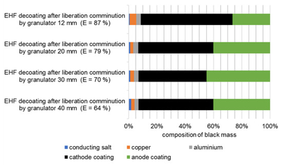
Figure 10.
Composition of the black masses of cell type 1 after decoating by EHF.
Comparable tests with mechanically pre-treated cathode foils achieved complete decoating of the cathode, but then showed a proportion of metallic impurities of 7% in the fraction <50 µm. It is assumed that the comparatively high proportion of impurities can be reduced by further optimisation and continuous operation of EHF [27].
Within the scope of test series 2 B, it was also investigated to decoat the electrode foils to the highest extent possible by intensifying the stress. For this purpose, a two-stage stress method was selected (Section 2.3).
The result shows a similar overall decoating of the foils as the single-stage treated foils with the same pre-shredding, although considerably more energy was introduced and the dwell time was significantly longer. Furthermore, the separated black mass showed a very high proportion of metallic impurities at just under 15%. It is assumed that here, as in test series 1, the mobility of the films in the reactor was impeded and only a few pieces of foil absorbed a large part of the energy. From this, it can be concluded that process parameters, such as the filling level and/or electrode spacing, were not optimally selected for this material. The deformation of the partially coated films, and thus a confinement of the coating, can be a further explanation for the limitations of the decoating process.
Figure 11 shows examples of the electrode foils from this test with the two-stage stress method. The perforated edges are clearly visible, especially on the anode foil (Cu). On the cathode (Al), on the other hand, the adherent coating can still be seen. Both examples also show holes in the centre of the foil piece. These probably originate from breakdowns of the discharges when the foil was between the electrodes at the time of the sparkover. Similar effects are also seen in the electrodynamic fragmentation of type 18,650 cells using a system from SELFRAG AG. The experiments were carried out as part of a master’s thesis at the University of Liège [31]. Pieces of foil after comminution in the granulator (right) serve as a comparison. Here, adhesions to the cathode foil are still visible as well, but the pieces are generally larger and not perforated.

Figure 11.
Representative foil pieces after EHF stress (left) and after comminution in the granulator (right).
3.4. Energy Consumption and Product Qualities
Both the literature and the experiments carried out show that the disintegration of intact battery cells by EHF can only be carried out incompletely or with a comparatively large expenditure of energy. This also applies to manually or mechanically pre-damaged cells. A value of around 1000 kWh/t can be assumed for the disintegration of round cells of type 18,650 by EHF, whereas a value of 60 kWh/t is assumed for pouch cells [27]. A disintegration with the combination of rotor shear and granulator used in this study achieves a comparable process result at less than 8 kWh/t. Figure 12 illustrates this with the stress energies required for the disintegration of different types and sizes of battery cells. A preferential decoating of the anode can be observed for both EHF and use of the granulator. This effect is therefore not system-specific but material-specific.
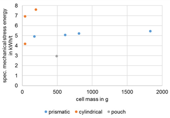
Figure 12.
Stress energy for comminution of different types and sizes of battery cells by means of rotor shears and granulator.
In this study, no direct comparisons can be made between the liberation of valuable materials in the granulator and the decoating tests carried out using EHF, as these are successive processes with correspondingly different starting materials. In this respect, Figure 13 shows the decoating of the conductor foils depending on the stress energy. As shown in the previous section and in Figure 6 and Figure 7, applying EHF increases decoating.
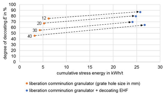
Figure 13.
Dependence of decoating on stress energy.
The combination of disintegration at 30 mm in the granulator with subsequent stressing via EHF achieves decoating similar to the disintegration with 20 mm grate with an energy requirement that is higher by a factor of five. This advantage of the granulator is contrasted by the lower throughput of the plant with smaller grate widths as well as the finer-grained, and thus more difficult-to-process, comminution product.
A decoating of coarsely liberated electrode foils by EHF thus seems more promising with regard to the subsequent separation. According to literature [27], the remaining 10–20 ma.-% of the coating of a mechanically pre-treated cathode foil can be removed with a total energy consumption of 150–200 kWh/t.
Values of 250–300 kWh/t for a complete decoating and 120 kWh/t for a 60 percent decoating can be found in the literature for stress on pure electrode foils [17,27]. Tests with purely mechanical stress for similar feed materials show a necessary stress energy of about 25 kWh/t for a complete decoating [16].
With regard to the degree of decoating and the energy to be expended, the present study shows that conventional mechanical stressing is advantageous compared to EHF. The metallic contamination of the black mass is approximately 7 ma.-% for a complete decoating for both processes [16,27]. This value refers to black mass of <50 µm in the case of EHF and to black mass of <500 µm in the case of conventional processing. The coarser pieces of the decoated conductor foils of the conventional preparation can thus also fall back on a larger selection of sorting processes if the mixture has to be further prepared.
Continuous process control of EHF can increase throughput and optimise energy consumption [23,27]. In this context, the conclusions and comparisons drawn here should be re-evaluated in the future.
3.5. Process Water Composition
Demineralised water with a conductivity of approximately 0.4 µS/cm was used for the experiments. The dissolution of the conducting salt and its decomposition products, as well as the dissolution of various other substances, for example through the delithiation of the active material, increases the conductivity of the process water and can thus have a significant influence on the process result.
For the experiments on the liberation of valuable materials of pre-damaged cells (Section 3.1), the ICP analysis resulted in a dissolved salt mass of nearly 13 g. Due to the dissolution of the salt, there is a risk of HF formation, which entails increased safety measures for this process. This reaction has been investigated in several publications and it was found that HF can be formed by several interdependent reactions [39,40,41]. Other investigations could not detect HF under comparable circumstances [27]. However, a pH value of about 7 was measured when processing whole battery cells and a pH value of up to 13 was measured when feeding pure cathode foils. This strongly basic value of pure cathode foils at least suggests the formation of an acid during the processing of whole cells. However, this effect is not yet clearly comprehensible.
It should also be noted that a higher salt concentration increases the electrical conductivity of the process water. For this purpose, the conductivity of the process water from the experiment in Section 3.1 was determined approximately 24 h after the tests. The comminuted product was stored in the process water during this time. The conductivity was 2500 µS/cm, which is approximately 6000 times the conductivity of the process water before the test. According to ImpulsTec GmbH, this value does not correspond to the usual empirical values, where the conductivity of the process water after a test with material from LIBs is around 500–1000 µS/cm. A possible reason for this difference could be that the conductivity of the described experiment was measured about 24 h after it was carried out. During this time, more substances than usual could dissolve directly during the experiment. Furthermore, the resulting conductivity strongly depends on the type of battery used and the mass ratio between battery and process water.
The fact is that an increase in conductivity initially favours the growth of pre-discharge channels. However, if this rises too far, the negative effect of the too rapid voltage decrease during the ignition delay time predominates [28]. This means that the process water of EHF must be treated at regular intervals in order to keep the conductivity in the optimal range for a targeted discharge of the EHF electrodes.
4. Summary
The aim of the research was to investigate the possible applications of electrohydraulic fragmentation in the recycling of prismatic lithium-ion battery cells from the automotive sector. For this purpose, a variety of process routes were investigated in order to evaluate if EHF can supplement or replace classic mechanical processing. The literature research showed that a comminution of undamaged, non-prismatic LIB cells with the help of EHF is very energy-intensive. Pre-damaged cells, on the other hand, can be liberated by EHF with a higher energy efficiency.
Therefore, in this study, prismatic cells were disintegrated in a rotor shear or granulator in order to generate more surface area prior to EHF. Nevertheless, EHF is only suitable to a limited extent for the liberation of pre-damaged prismatic battery cells in a batch operation. A complete disintegration of all valuable materials was not possible to achieve. For such a feed material, the process control must be changed, e.g., to continuous operation. Alternatively, a mechanical comminution can be used as previous step followed by EHF to decoat electrode foils. Although this procedure increases the mechanical effort, it reduces the specific electrical energy required for liberation. Compared to that, a conventional granulator proved to be advantageous over the discontinuously operating EHF.
Concerning decoating, corresponding publications show that optimised test conditions at higher stress intensities and energy inputs results in a higher decoating of the electrodes, as well as a selective decoating in favour of the anode. However, a higher energy input is associated with a comminution of the metal foils of the electrode and thus with an increasing contamination of the corresponding fine black mass fraction and a reduced recovery of metal concentrates.
Further, in our tests, the anode foil is, on average, better decoated than the cathode foil. The enrichment ratio i for the coating of the anode is above 1 in all tests. A clear selectivity with i > 1.65 was only shown when pre-crushing in the granulator with coarse grate widths (30 and 40 mm) was combined with subsequent decoating by EHF. This confirms the hypothesis made in [16] that selective decoating is only possible if liberation is carried out with as little energy input as possible in order to utilize the different adhesive forces of the coatings on the conductor foils [34].
Processing in an aqueous medium results in both the risk of hydrofluoric acid formation and a loss of valuable substances into the process water. As an example, the delithiation of the active material can be mentioned here, whereby lithium-nickel-aluminium-oxide (NCA) is most strongly affected [27]. This simultaneously increases the conductivity of the liquid medium. All in all, this requires both a treatment of EHF process water and a treatment of the active material for reuse. Furthermore, high safety precautions must be taken due to the possibility of toxic HF formation.
Regarding economic evaluation, the wear of the machines, contamination, and recycling recyclability of the specific black mass intermediate and the throughput have to be considered in future studies. Compared to dry processing, EHF will always have additional expenses for drying the material and treating the process water. On the other hand, many safety hazards, like evaporation of electrolyte [42], are eliminated in wet processing. Therefore, the search of a profitable and scalable processing route for EOL LIBs will be the focus of future research projects.
Author Contributions
T.M. and T.L. developed the idea and the content of the report; T.L. conducted the experiments, analysed the resulting data and results, and wrote the article; U.A.P. and T.M. revised the article several times and improved both the presentation of the results and the structure of the chapters; everything took place under the supervision of U.A.P. All authors have read and agreed to the published version of the manuscript.
Funding
EIT RawMaterials, Co-funded by the European Union, EU/KIC-Projekt Nr. 17163.
Institutional Review Board Statement
Not applicable.
Informed Consent Statement
Not applicable.
Data Availability Statement
The data can be obtained from the authors on request.
Acknowledgments
The authors would like to thank ImpulsTec GmbH in Radebeul (Germany), with whose support and technology the experiments were carried out, and SAMSUNG SDI Battery Systems GmbH in Premstätten (Austria) for providing LIBs within the framework of the EU/KIC project AutoBatRec.
Conflicts of Interest
The authors declare no conflict of interest.
References
- Linke, G. Entwicklungsstand der elektro-hydraulischen Zerkleinerung. Chem. Ing. Tech. 1968, 40, 117–120. [Google Scholar] [CrossRef]
- Yutkin, L.A. Electrohydraulic Effect; Mashgiz (State Scientific Technical Press for Machine Construction Literature): Moscow, Russia, 1955. [Google Scholar]
- Rumpf, H. Die Einzelkornzerkleinerung als Grundlage einer technischen Zerkleinerungswissenschaft. Chem. Ing. Techn. 1965, 37, 187–202. [Google Scholar] [CrossRef]
- Mueller, A.; Linß, E.; Wollenberg, G.; Scheibe, H. Elektrohydraulische Zerkleinerung von Altbeton: Neue Ergebnisse und Perspektiven. Ratg. Abbruch Recycl. 2004, 2004, 5159. [Google Scholar]
- Eisert, S.; Pieplow, G. Processing of metallurgical slags with shock wave technology. Recovery 2017, 7, 27–33. [Google Scholar]
- Eisert, S.; Bartkowski, J. Innovative recycling with shock wave technology. Recovery 2016, 6, 46–56. [Google Scholar]
- Horn, D.; Zimmermann, J.; Stauber, R.; Gutfleisch, O. New efficient Recycling Process for Li-ion Batteries. In Conference on Future Automotive Technology; Springer: Berlin/Heidelberg, Germany, 2013. [Google Scholar]
- Schubert, G. Zerkleinerungstechnik für nicht-spröde Abfälle und Schrotte. AT. Aufbereit.-Tech. 2002, 43, 6–23. [Google Scholar]
- Schubert, H. Aufbereitung Fester Mineralischer Rohstoffe, 3rd ed.; Kausch, P., Bertau, M., Gutzmer, J., Matschullat, J., Eds.; Dt. Verl. für Grundstoffindustrie: Leipzig, Germany, 1975; p. 360 S. [Google Scholar]
- Werner, D.; Peuker, U.A.; Mütze, T. Recycling Chain for Spent Lithium-Ion Batteries. Metals 2020, 10, 316. [Google Scholar] [CrossRef] [Green Version]
- Korthauer, R. Lithium-Ion Batteries: Basics and Applications; Springer: Berlin/Heidelberg, Germany, 2018. [Google Scholar]
- Shiqi, L.; Dan, L.; Wenyue, L.; Long, Q.; Zhihua, D.; Zhiqun, C.; Zhaoyang, F. Recent progress in developing Li2S cathodes for Li–S batteries. Energy Storage Mater. 2020, 27, 279–296. [Google Scholar] [CrossRef]
- Miaolun, J.; Yangfeng, W.; Chenliang, Y.; Chengyang, W.; Wenkui, Z.; Chu, L. High-capacity SiOx (0 ≤ x ≤ 2) as promising anode materials for next-generation lithium-ion batteries. J. Alloy. Compd. 2020, 842, 155774. [Google Scholar]
- Naoki, N.; Feixiang, W.; Jung Tae, L.; Gleb, Y. Li-ion battery materials: Present and future. Mater. Today 2015, 18, 252–264. [Google Scholar]
- Perner, A.; Vetter, J. 8—Lithium-Ion Batteries for Hybrid Electric Vehicles and Battery Electric Vehicles; Woodhead Publishing Series in Energy: Sawston, UK, 2015; pp. 173–190. [Google Scholar]
- Wuschke, L. Mechanische Aufbereitung von Lithium-Ionen-Batteriezellen, 1st ed.; TU Bergakademie Freiberg: Freiberg, Germany, 2018. [Google Scholar]
- Leißner, T.; Hamann, D.; Wuschke, L.; Jäckel, H.-G.; Peuker, U.A. High voltage fragmentation of composites from secondary raw materials—Potential and limitations. Waste Manag. 2018, 74, 123–134. [Google Scholar] [CrossRef] [PubMed]
- Mativenga, P.T.; Shuaib, N.A.; Howarth, J.; Pestalozzi, F.; Woidasky, J. High voltage fragmentation and mechanical recycling of glass fibre thermoset composite. CIRP Ann. 2016, 65, 45–48. [Google Scholar] [CrossRef]
- Andres, U. Development and prospects of mineral liberation by electrical pulses. Int. J. Miner. Processing 2010, 97, 31–38. [Google Scholar] [CrossRef]
- Chernet, T. High Voltage Selective Fragmentation for Detailed Mineralogical and Analytical Information, Case Study: Oiva’s Gold-Quartz-Dyke in the Lapland Granulite Belt, Laanila, Northern Finland; Springer: Berlin/Heidelberg, Germany, 2012. [Google Scholar]
- Orzol, C.H.M.; Lieberwirth, H. Elektrohydraulische Zerkleinerung von carbonfaserverstärkten Kunststoffen für das Carbonfaser-Recycling. Chem. Ing. Tech. 2019, 91, 160–166. [Google Scholar] [CrossRef] [Green Version]
- Bertram, A. Innovative Technologien für Ressourceneffizienz-Forschung zur Bereitstellung wirtschaftsstrategischer Rohstoffe (r4): Ergebnisse: Gefördert vom Bundesministerium für Bildung und Forschung: FONA Ressourceneffizienz BMBF. In NeW-Bat Neue Energieeffiziente Wiederverwertung von Batteriematerialien; Fraunhofer-Projektgruppe IWKS, Ed.; CUTEC Clausthaler Umwelttechnik Forschungszentrum der TU Clausthal: Clausthal-Zellerfeld, Germany, 2019; p. 120. [Google Scholar]
- ImpulsTec GmbH. ImpulsTec gelingt Durchbruch im Batterierecycling. EU-Recycl. 2020, 37, 55. [Google Scholar]
- Pinegar, H.; Smith, Y.R. Recycling of End-of-Life Lithium-Ion Batteries, Part II: Laboratory-Scale Research Developments in Mechanical, Thermal, and Leaching Treatments. J. Sustain. Metall. 2020, 6, 142–160. [Google Scholar] [CrossRef]
- Marshall, J.; Gastol, D.; Sommerville, R.; Middleton, B.; Goodship, V.; Kendrick, E. Disassembly of Li Ion Cells—Characterization and Safety Considerations of a Recycling Scheme. Metals 2020, 10, 773. [Google Scholar] [CrossRef]
- Schäfer, J.; Singer, R.; Hofmann, J.; Fleischer, J. Challenges and Solutions of Automated Disassembly and Condition-Based Remanufacturing of Lithium-Ion Battery Modules for a Circular Economy. Procedia Manuf. 2020, 43, 614–619. [Google Scholar] [CrossRef]
- Neue Energieeffiziente Wiederverwertung von Batteriematerialien—New-Bat; Fraunhofer IWKS: Rhine/Main, Germany, 2019.
- Zange, R.M. Anwendungsbezogenes Prozeßmodell der Wandlung Elektrischer Energie in Energie des Leistungsschallimpulses. In Fakultät für Elektrotechnik und Informationstechnik; Otto-von-Guericke-Univeristät Magdeburg: Magdeburg, Germany, 2000. [Google Scholar]
- Öhl, J.; Horn, D.; Zimmermann, J.; Stauber, R.; Gutfleisch, O. Efficient Process for Li-Ion Battery Recycling via Electrohydraulic Fragmentation. Mater. Sci. Forum 2019, 959, 74–78. [Google Scholar] [CrossRef]
- Moradi, B.; Botte, G.G. Recycling of graphite anodes for the next generation of lithium ion batteries. J. Appl. Electrochem. 2016, 46, 123–148. [Google Scholar] [CrossRef]
- Veress, E.-C. Pretreatment, Processing and Recycling-Oriented Characterization of Micromobility Spent Lithium-Ion Batteries. In Emerald; Université Liège: Liège, Belgium, 2020. [Google Scholar]
- Blanka, S.; Raymond, J.; Jörg, A.P. Testing the influence of high-voltage mineral liberation on grain size, shape and yield, and on fission track and 40Ar/39Ar dating. Chem. Geol. 2014, 371, 83–95. [Google Scholar]
- Bluhm, H.; Frey, W.; Giese, H.; Hoppe, P.; Schultheiss, C.; Strassner, R. Application of pulsed HV discharges to material fragmentation and recycling. IEEE Trans. Dielectr. Electr. Insul. 2000, 7, 625–636. [Google Scholar] [CrossRef]
- Wuschke, L.; Jäckel, H.-G.; Leißner, T.; Peuker, U.A. Crushing of large Li-ion battery cells. Waste Manag. 2019, 85, 317–326. [Google Scholar] [CrossRef]
- Kwade, A.; Diekmann, J. Recycling of Lithium-Ion Batteries: The LithoRec Way; Springer International Publishing: Berlin/Heidelberg, Germany, 2017. [Google Scholar]
- Gellner, M.; Wuschke, L.; Jäckel, H.-G.; Peuker, U.A. Akkus mechanisch aufbereiten. RECYCLING Mag. 2015, 16, 26–29. [Google Scholar]
- Jäckel, H.G.; Wuschke, L.; Peuker, U.A. Problems in Processing of Metalliferous Composites from Lithium-Containing Electrical Devices and Batteries. Chem. Ing. Tech. 2014, 86, 806–813. [Google Scholar] [CrossRef]
- Woldt, D. Zerkleinerung Nicht-Spröder Stoffe in Rotorscheren und -reißern, 1st ed.; Freiberger Forschungshefte/A; Technische Universität Bergakademie Freiberg: Freiberg, Germany, 2005. [Google Scholar]
- Plakhotnyk, A.V.; Ernst, L.; Schmutzler, R. Hydrolysis in the system LiPF6—propylene carbonate—dimethyl carbonate—H2O. J. Fluor. Chem. 2005, 126, 27–31. [Google Scholar] [CrossRef]
- Terborg, L.; Nowak, S.; Passerini, S.; Winter, M.; Karst, U.; Haddad, P.R.; Nesterenko, P.N. Ion chromatographic determination of hydrolysis products of hexafluorophosphate salts in aqueous solution. Anal. Chim. Acta 2012, 714, 121–126. [Google Scholar] [CrossRef]
- Stich, M. Wasserverunreinigungen in Lithium-Ionen-Batterien. In Fakultät für Elektrotechnik und Informationstechnik; Technische Universität Ilmenau: Ilmenau, Germany, 2019. [Google Scholar]
- Werner, D.M.; Mütze, T.; Peuker, U.A. Influence of cell opening methods on organic solvent removal during pretreatment in lithium-ion battery recycling. Waste Manag. Res. 2021. [Google Scholar] [CrossRef]
Publisher’s Note: MDPI stays neutral with regard to jurisdictional claims in published maps and institutional affiliations. |
© 2022 by the authors. Licensee MDPI, Basel, Switzerland. This article is an open access article distributed under the terms and conditions of the Creative Commons Attribution (CC BY) license (https://creativecommons.org/licenses/by/4.0/).