Abstract
The mixed metal oxides Bi2MoO6 and La-doped Bi2MoO6 were prepared by the sol–gel method. Then, varying quantities of the as-prepared mixed metal oxides were blended with graphene oxide (GO), employing sonication, to obtain Bi2MoO6/GO (BM/GO) and La-Bi2MoO6/GO (LBM/GO) nanocomposites. These prepared materials were characterized by different techniques such as thermal gravimetric analysis (TGA), X-ray diffraction (XRD), Brunauer-Emmett-Teller (BET), X-ray photoelectron spectroscopy (XPS), scanning electron microscope (SEM), and transmission electron microscopy (TEM). Dielectric properties were studied by using a precision impedance analyzer. Dielectric constant and loss tan of the synthesized composites were studied as a function of frequency by using a precision impedance analyzer. Overall, the dielectric constant (ɛ’) observed for the LBM/GO composites was higher than that of BM/GO.
1. Introduction
A growing demand for electric charge storage devices, due to the invention of battery-powered automobiles and other devices, has led to the study of the preparation of materials with enhanced dielectric properties. A variety of nanocomposites such as Mn-substituted ZnFe2O4; Co2Y hexaferrites substituted by Mn-Ge, Ce-Nd2Zr2O7, Co(II), Ni(II), Cu(II), and Mn(II)-oxaloyldihydrazone complexes; and ZnO microspheres with polyaniline (PANI) have been studied for their dielectric behaviors due to the fact that nanocomposites possess unique properties as compared to bulk material [1,2,3]. Nanocomposites have great importance due to their remarkable catalytic, dielectric, and luminescence properties, based on the morphology of the nanomaterials. The electrical conductance and thermal stability of the metal nanocomposites can be improved by the help of a carbon-based support, usually achieved with graphene oxides [4,5].
One such carbon-based support is graphene, a 2D material that has been found to be an excellent support for the enhancement of properties of the resulting nanocomposites [6,7,8,9,10,11,12,13]. Various reports of the use of graphene can be found in the literature, such as poly (p-phenylene benzobisoxazole/graphene, PVA/graphene composites graphene oxide (GO)/ZnxFe1−xFe2O4 composites, graphene/BaTiO nanocomposites rGO-Cu2O, etc., for the creation of nanocomposites that display enhanced dielectric properties due to the inclusion of graphene [14,15,16].
Furthermore, the incorporation of metals and non-metals with metal oxides nanoparticles also enhances the functionality of the materials. One such metal that has been extensively studied is bismuth, and there are a series of nanocomposites (Bi2WO6, BaTiO3Bi2O3, Bi2S3, BiVO4, Bi2Ti2O7, Bi12TiO20 and Bi2InNbO7) that show a variety of properties [17,18,19,20,21]. Bismuth molybdate (Bi2MoO6) is a versatile metal molybdate with photoelectric characteristics that has been widely used as a photocatalyst and as an anode material in lithium batteries. Some notable citations in this regard are available in the literature [22,23,24,25,26].
Recently, bismuth molybdate (Bi2MoO6) was employed as a photocatalyst, exhibiting increased performance among metal molybdates for the degradation of dyes and luminescence, and it has been synthesized by various methods: co-precipitation, hydrothermal, solid state reaction, and sol–gel [27]. In continuation of our efforts to prepare various graphene-based nanocomposites, we extended our previous work regarding synthesis and morphological studies of Bi2MoO6 and La-doped Bi2MoO6 [28,29,30], and herein we report on the graphene oxide nanocomposites of Bi2MoO6 and La-doped Bi2MoO6, i.e., Bi2MoO6/GO and La-Bi2MoO6/GO composites, respectively, and their dielectric behavior.
2. Materials and Methods
2.1. Materials
All chemicals used for the synthesis, such as graphite powder, sodium molybdate (Na2Mo2O4 × 2H2O), bismuth chloride (BiCl3), and lanthanum chloride (LaCl3 × 7H2O), were of analytical grade purchased from Sigma Aldrich and PubChem (Saint Louis, MO, USA). Bi2MoO6 and La-doped Bi2MoO6 were synthesized using a previously reported method [28].
2.2. Methods
Graphene oxide was synthesized by the modified Hummers method [31]. A variety of nanocomposites of bismuth molybdate and lanthanum-doped bismuth molybdate with graphene oxide were synthesized by depositing varying amounts by weight of Bi2MoO6 and La-BiMoO6 on graphene oxide to yield 2, 3, and 4% of Bi2MoO6/GO (BM/GO) and La-Bi2MoO6/GO (LBM/GO). The mixed metal oxides and graphene oxide were dispersed in deionized water by applying sonication for 3 h. After sonication, the samples were dried in an electric oven at 90 °C for 48 h, and we obtained X% BM/GO (X wt.% Bi2MoO6/GO) and X% LBM/GO (X wt.% La-Bi2MoO6/GO) composites, where X = 2, 3, or 4, which denotes the wt.% of the mixed metal oxide in the GO nanocomposite.
2.3. Characterization
The crystalline structures of the as synthesized nanocomposites were characterized with XRD patterns on a Bruker D2 Phaser X-ray diffractometer with Cu Kα radiation (λ = 1.5418 Å), having accelerating voltage and current of 30 kV and 10 mA, respectively (Bruker, Berlin, Germany). TGA was performed by heating the samples in an N2 flow using a Perkin-Elmer Thermogravimetric Analyzer 7 with a heating rate of 10 °C/min (Perkin-Elmer, Waltham, MA, USA). BET surface area and BJH pore volume were measured by an N2 adsorption-desorption isotherm with a liquid nitrogen temperature of −196 °C using Micromeritics (Gemini VII, 2390 surface area and porosity, Norcross, GA, USA). The samples were degassed at 120 °C for 3 h using N2 gas. The surface morphology of the nanocomposites was determined by scanning electron microscopy (SEM, Jeol, JED-2200 series, Tokyo, Japan). Transmission electron microscopy (TEM) analysis of nanocomposite measurements was carried out using Jeol TEM model JEM-1011 (Jeol, Tokyo, Japan) at 100 keV. XPS spectra were measured on a PHI 5600 Multi-Technique XPS (Physical Electronics, Lake Drive East, Chanhassen, MN, USA) using monochromatized Al Ka at 1486.6 eV.
3. Results and Discussions
3.1. Thermal Gravimetric Analysis
A thermal gravimetric analysis (TGA, Perkin-Elmer, Waltham, MA, USA) was conducted to identify the thermal behavior of all the synthesized composites. The results of 4% BM/GO and 4% LBM/GO are compared in Figure 1, while the TGA curves of other compositions are given in the supplementary data (Figure S1). Among these composites, in general, a large weight loss was observed between 220 and 445 °C, which can be attributed to the thermal decomposition of rGO in these composites. Such a large loss is in agreement with similar degradation patterns of Bi2MoO6/rGO composites [22]. The TGA thermogram of Bi2MoO6 reveals that there was an 8% weight loss and that of La-Bi2MoO6 shows a weight loss of up to 16%, indicating that the later nanocomposite is thermally less stable than its precursor. However, when the GO nanocomposites of the mixed metal oxides BM and LBM, i.e., X% Bi2MoO6/GO and X% La-Bi2MoO6/GO, were subjected to similar studies wherein the samples were heated up to 800 °C starting from 25 °C at a heating rate of 10 °C/min under an inert atmosphere, a similar trend of thermal stability was observed, indicating the formation of composites. However, when the La-doped Bi2MoO6 was subjected to a similar study, it was found that the weight loss was up to 16%, indicating that the later nanocomposite, i.e., 4% LBM/GO, is thermally less stable.

Figure 1.
Comparative thermal degradation patterns of Bi2MoO6 (BM), La-Bi2MoO6 (LBM), graphene oxide (GO), 4% BM/GO, and 4% LBM/GO.
3.2. X-ray Diffraction
The XRD pattern of the prepared 4% BM/GO and 4% LBM/GO composites is given in Figure 2. The diffractogram obtained for the sample of 4% BM/GO revealed the presence of GO along with the pattern of Bi2MoO6 (JCPDS No. 76-2388), which yielded diffraction peaks at 2θ values 23.5° (111), 28.2° (131), 32.5° (002), 33.2° (060), 36.1° (151), 46.8° (202), 47.2° (260), 55.5° (133), 56.4° (191), and 58.4° (262) that were found in the original mixed metal oxide BM [32]. However, the XRD pattern of 4% LBM/GO revealed the presence of mixed phases of La2Mo2O9 and Bi2MoO6 along with GO [32,33,34].

Figure 2.
Comparative XRD patterns of BM, 4% BM/GO, and LBM, 4% LBM/GO composites.
3.3. BET Analysis
The nitrogen adsorption isotherms of 4% BM/GO and 4% LBM/GO composites measured at 333K are shown in Figure 3. From the isotherms obtained, it can be observed that the adsorption of N2 was much higher in the composites than in their precursors, suggesting that the enormous alteration of structural characteristics takes place due to incorporation of GO in the system [35]. Moreover, the surface area of the 4% BM/GO and 4% LBM/GO composites was found to be 12 m2/g and 10.7 m2/g, respectively, which is several times greater than that of the precursors Bi2MoO6 (1.0277 m2/g) and La-doped Bi2MoO6 (3.4077 m2/g), respectively [28]. This difference in surface area can also be attributed to the GO incorporation with BM and LBM precursors [36].
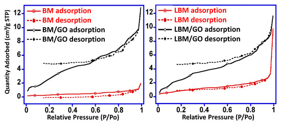
Figure 3.
Nitrogen adsorption isotherms of 4% BM/GO and 4% LBM/GO composites.
Furthermore, when comparing the pore distribution of the composites with the precursor metal oxides, i.e., BM and LBM, it was observed that the pore size of the composites ranged from 1.1 to 18.6 × 10⁻³ cm3/g and 2.8 to 19.7 × 10⁻³ cm3/g for the 4% BM/GO and 4% LBM/GO composites, respectively (Figure 4).

Figure 4.
Pore distribution curves of 4% BM/GO and 4% LBM/GO composites.
3.4. Microscopic Analysis
The surface morphology of the prepared 4% BM/GO and 4% LBM/GO composites was examined by SEM, and the respective SEM micrograms are shown in Figure 5. The surface morphology of 4% BM/GO possesses irregular shining particles with small crystals of bismuth molybdate on a graphene oxide platform. The surface morphology of 4% LBM/GO exhibits a distribution of particles arranged as relatively large rod-like crystals of lanthanum molybdate embedded on a graphene oxide platform. The surface morphology of both composites is quite different than that of Bi2MoO6 and La-Bi2MoO6, which are dense rod-like and scattered granular, respectively [28].

Figure 5.
Scanning electron micrograms of 4% BM/GO and 4% LBM/GO composites.
The prepared composites were subjected to TEM analysis by dispersing the prepared composites in hexane and using a sonicator water bath, then, the dispersed solution was dropped on the TEM grid to evaluate the dispersion of BM and LBM on the graphene oxide sheets. It was observed that the dispersion of LBM, i.e., La-Bi2MoO6, on the graphene oxide sheets in the composite 4% LBM/GO was superior to that observed in the case of BM, i.e., Bi2MoO6 in the 4% BM/GO composite, wherein agglomeration of the mixed metal oxides was seen on the surface of the GO. The TEM images obtained for both the composites, i.e., 4% BM/GO and 4% LBM/GO, are given in Figure 6.
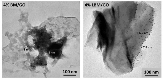
Figure 6.
Transmission electron microscopy analysis of 4% BM/GO and 4% LBM/GO composites.
3.5. X-ray Photoelectron Spectroscopy
X-ray photoelectron spectroscopy is one of the best tools to analyze the surface composition and particularly the valence state of elements in these composites. The scan of the 4% LBM/GO composite revealed the presence of Bi, Mo, O, and La elements in the prepared composites, and an additional signal corresponding to the element C revealed the successful doping of GO in the nanocomposite (Figure 7). The full spectrum for the 4% LBM/GO composite contains peaks for C 1s (287 eV), O 1s (537 eV), Mo 3d (235 eV), Bi 4f (158 eV), and La 3d. These results are in agreement with previous literature [22,28]. It was observed that there was no change in the binding energies of the respective elements of the mixed metal oxides, indicating that the formation of the composites is by physisorption of the mixed metal oxides, i.e., BM and LBM, on the surface of the employed GO, as confirmed by the TEM images.

Figure 7.
XPS spectra of the 4% LBM/GO composite.
3.6. Dielectric Properties
Dielectric properties of Bi2MoO6/GO and La-Bi2MoO6/GO as a function of frequency were studied by using an impedance analyzer, and the values of the dielectric constants were plotted against the log of frequency, as shown in Figure 8a,b and Figure 9a,b. Figure 8a,b shows the increase in dielectric constant from X% BM/GO (X = 2, 3, and 4). ɛ’ decreases with an increase in frequency. High dielectric constants at low frequencies were attributed to the electrode polarization phenomenon, wherein an increase in of the electrode potential lags behind the frequency, and space charges have less time to be arranged according to the applied electric field [37]. An increase in ɛ’ was observed with an increase in BM content from 2 to 4% in the GO nanocomposite. Values of ɛ’ were 17.69, 76.67, and 142.33 for 2, 3 and 4%, respectively. A high dielectric constant was considered due to the electronic and ionic polarizability, and contribution by the oxide contents and Bi ions mainly contributed to the high ɛ’ [38,39]. Moreover, existence of the oxygenated groups in the GO caused entrapment of Bi ions and reduced the interaction of Bi with molybdate ions, and hence, more available Bi caused a high ɛ’ [40]. ɛ’ observed for the LBM/GO composites was higher than that of the undoped nanocomposite, i.e., BM/GO, but overall, the value of the ɛ’ was much lower than that of Bi2MoO6/GO. Values observed for the ɛ’ of La-Bi2MoO6/GO, which were 43.9, 48.89, and 51.28 for 2, 3, and 4% weight of La-Bi2MoO6, dispersed in a fixed amount of GO. The low ɛ’ was attributed to the increased conductivity of the oxide ions in La-doped Bi2MoO6 [41].

Figure 8.
(a): Comparative graphs between the dielectric constant (ɛ’) and log f for composites X% BM/GO (X = 2, 3, and 4) (b) X% LBM/GO (X = 2, 3, and 4).
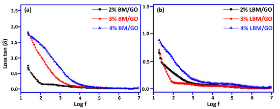
Figure 9.
(a): Comparative graphs between tan δ and log f for composites X% BM/GO (X = 2, 3, and 4) (b) X% LBM/GO (X = 2, 3, and 4).
The loss tangents (tan δ) for Bi2MoO6/GO and La-Bi2MoO6/GO plotted against frequency, as shown in Figure 9a,b, show a similar behavior as that of ɛ’. Values of tan δ were 0.75, 1.82, and 1.79 for 2, 3, and 4% weight of Bi2MoO6, respectively, and the values of tan δ of La-Bi2MoO6/GO were 0.65, 0.71, and 0.88, respectively. The increase in tan δ with the increase in Bi2MoO6 content in GO is attributed to the conductive nature of Bi2MoO6 [42], while the increase in tan δ with increase in Bi2MoO6/GO is attributed to the conductive network formation, dipole polarization, and interfacial polarization [43], as there exists a relation between electrical conduction ɛ’ and ɛ’’ [44,45].
4. Conclusions
Composites of GO/Bi2MoO6 and La-doped GO/Bi2MoO6 were synthesized by sonication. An increase in the dielectric constant with an increase in Bi2MoO6 content was observed with an ɛ’ of 142.33 at 4 wt.% of Bi2MoO6. A similar increasing trend was shown for La-doped Bi2MoO6, with an overall value of ɛ’ 51.28. Tan δ was 1.79 and 0.88 for 4% GO/Bi2MoO6 and La-doped GO/Bi2MoO6, respectively. Overall, the present work opens an avenue for the controlled synthesis of GO/Bi2MoO6 and La-doped GO/Bi2MoO6 and directs our attention to new roles of GO in the controllable synthesis of new materials for possible applications in capacitive and charge storage devices.
Supplementary Materials
The following are available online at https://www.mdpi.com/article/10.3390/met11040559/s1, Figure S1: Comparative thermal degradation patterns of (a) BM, LM, GO, 2% BM/GO, 3% BM/GO, 2% LBM/GO, and 3% BM/GO.
Author Contributions
Conceptualization, M.I. and S.F.A.; methodology, S.L., M.W., and S.F.A.; software, M.W.; validation, M.W. and S.F.A.; formal analysis, M.W., M.I., S.N., M.K., and M.R.S.; investigation, S.L., M.I., S.N., M.K., and M.R.S.; resources, M.I. and S.F.A.; data curation, S.L., M.I., S.N., M.K., and M.R.S.; writing—original draft preparation, M.W. and S.F.A.; writing—review and editing, M.W., S.F.A., M.K., and M.R.S.; visualization, M.R.H.; supervision, M.I., S.F.A., and M.R.H.; project administration, M.R.H.; funding acquisition, M.R.H. All authors have read and agreed to the published version of the manuscript.
Funding
The authors extend their appreciation to the Deputyship for Research & Innovation, “Ministry of Education” in Saudi Arabia for funding this research work through the project number IFKSURG-2020-142.
Institutional Review Board Statement
Not applicable.
Informed Consent Statement
Not applicable.
Data Availability Statement
Data are contained within the article or Supplementary Material.
Acknowledgments
The authors extend their appreciation to the Deputyship for Research & Innovation, “Ministry of Education” in Saudi Arabia for funding this research work through the project number IFKSURG-2020-142.
Conflicts of Interest
The authors declare no conflict of interest.
References
- Huebner, E.U. (Ed.) Nickel Alloys; Marcel Dekker Inc.: New York, NY, USA; Basel, Switzerland, 2000; 180p. [Google Scholar]
- Goldshtein, M.I.; Litvinov, V.S.; Bronfin, M.F. Metallophysics of High-Strength Alloys; Metallurgia: Moscow, Russia, 1986; 312p. [Google Scholar]
- Materials Parl. Nickel, Cobalt, and Their Alloys. ASM Speciality Handbook; Materials Parl; ASM International: Novelty, OH, USA, 2000; 400p. [Google Scholar]
- Bruckart, W.L.; Jaffee, R.I. Cladding of molybdenum for service in air at elevated temperature. Trans. Am. Soc. Met. 1952, 44, 44. [Google Scholar]
- Lurie, S.; Volkov-Bogorodskiy, D.; Solyaev, Y.; Rizahanov, R.; Agureev, L. Multiscale modelling of aluminium-based metal-matrix composites with oxide nanoinclusions. Comput. Mater. Sci. 2016, 116, 62–73. [Google Scholar] [CrossRef]
- Kostikov, V.I.; Agureev, L.E.; Eremeeva, Z.V. Development of nanoparticle-reinforced alumocomposites for rocket-space engineering. Russ. J. Non Ferr. Met. 2015, 56, 325–328. [Google Scholar] [CrossRef]
- Sharma, A.; Roh, M.-H.; Jung, D.-H.; Jung, J.-P. Effect of ZrO2 Nanoparticles on the Microstructure of Al-Si-Cu Filler for Low-Temperature Al Brazing Applications. Met. Mater. Trans. A 2016, 47A, 510–521. [Google Scholar] [CrossRef]
- Chuvil’deev, V.N.; Kopylov, V.I.; Zeiger, W. A theory of non-equilibrium grain boundaries and its applications to nano- and micro-crystalline materials processed by ECAP. Ann. Chim. Sci. Des Matériaux 2002, 27, 55–64. [Google Scholar] [CrossRef]
- Ohji, T.; Hirano, T.; Nakahira, A.; Niihara, K. Particle/Matrix interface and its role in creep inhibition in alumina silicon carbide nanocomposites. J. Am. Ceram. Soc. 1996, 79, 33–45. [Google Scholar] [CrossRef]
- Grigorovich, V.K.; Sheftel’, E.N. Dispersion Hardening of Refractory Metals; Nauka: Moscow, Russia, 1980; 304p. [Google Scholar]
- Gottstein, G. Physical Foundations of Materials Science; Springer: Berlin, Germany, 2004; 502p. [Google Scholar]
- Thompson, A.W. Substructure strengthening mechanisms. Met. Trans. 1977, 8A, 833–842. [Google Scholar] [CrossRef]
- Lugovskoi, Y.F. Effect of structure on the fatigue strength of dispersion-hardened condensated based on copper II. Analysis of the first coefficient of the Mott—Stroh relation. Powder Met. Met. Ceram. 1998, 37, 432–437. [Google Scholar] [CrossRef]
- Taira, S.; Otani, R. Theory of High Temperature Strength of Materials; Metallurgiya: Moscow, Russia, 1986; 280p. [Google Scholar]
- Springer Nature. Spark Plasma Sintering of Materials. Advances in Processing and Applications; Springer Nature: Cham, Switzerland, 2019; 767p. [Google Scholar]
- Borkar, T.; Banerjee, R. Influence of spark plasma sintering (SPS) processing parameters on microstructure and mechanical properties of nickel. Mater. Sci. Eng. A 2014, 618, 176–181. [Google Scholar] [CrossRef]
- Zhao, Y.; Topping, T.; Bingert, J.F.; Thornton, J.; Dangelewicz, A.; Li, Y.; Liu, W.; Zhu, Y.; Zhou, Y.; Lavernia, E. High Tensile Ductility and Strength in Bulk Nanostructured Nickel. Adv. Mater. 2008, 20, 3028–3033. [Google Scholar] [CrossRef]
- Naimi, F.; Minier, L.; Le Gallet, S.; Couque, H.; Bernard, F. Dense Nanostructured Nickel Produced by SPS from Mechanically Activated Powders: Enhancement of Mechanical Properties. J. Nanomater. 2013, 11. [Google Scholar] [CrossRef]
- Agureev, L.E.; Kostikov, V.I.; Yeremeyeva, Z.V.; Barmin, A.A.; Rizakhanov, R.N.; Ivanov, B.S.; Ashmarin, A.A.; Laptev, I.N.; Rudshteyn, R.I. Powder aluminum composites of Al–Cu system with micro-additions of oxide nanoparticles. Inorg. Mater. Appl. Res. 2016, 7, 507–510. [Google Scholar] [CrossRef]
- Mironov, V.V.; Agureev, L.E.; Eremeeva, Z.V.; Kostikov, V.I. Effect of Small Additions of Alumina Nanoparticles on the Strength Characteristics of an Aluminum Material. Dokl. Phys. Chem. 2018, 481, 110–113. [Google Scholar] [CrossRef]
- Lurie, S.; Belov, P.; Volkov-Bogorodsky, D.; Tuchkova, N. Interphase layer theory and application in the mechanics of composite materials. J. Mat. Sci. 2006, 41, 6693–6707. [Google Scholar] [CrossRef]
- Saunders, Z.; Noack, C.W.; Dzombak, D.A.; Lowry, G. Characterization of engineered alumina nanofibers and their colloidal properties in water. J. Nanoparticle Res. 2015, 17, 1–14. [Google Scholar] [CrossRef]
- Bravaya, N.M.; Galiullin, A.N.; Saratovskikh, S.L.; Panin, A.; Faingold, E.; Vasilev, S.G.; Bubnova, M.; Volkov, V. Synthesis and properties of hybrid materials obtained by in situ copolymerization of ethylene and propylene in the presence of Al2O3 nanofibers (NAFEN™) on catalytic system rac-Et (2-MeInd) 2ZrMe2/isobutylalumoxane. J. Appl. Polym. Sci. 2016. [Google Scholar] [CrossRef]
- Panda, P.K.; Ramakrishna, S. Electrospinning of Alumina Nanofibers Using Different Precursors. J. Mater. Sci. 2007, 42, 2189–2193. [Google Scholar] [CrossRef]
- Yang, C.; Huang, H.-F.; de los Reyes, M.; Yan, L.; Zhou, X.-T.; Xia, T.; Zhang, D.-L. Microstructures and Tensile Properties of Ultrafine Grained Ni- (1-3.5) wt.% SiCNP Composites Prepared by a Powder Metallurgy Route. Acta Met. Sin. 2015, 28, 809–816. [Google Scholar] [CrossRef]
- Maweja, K.; Phasha, M.; Yamabe-Mitarai, Y. Alloying and microstructural changes in platinum–titanium milled and annealed powders. J. Alloy. Compd. 2012, 523, 167–175. [Google Scholar] [CrossRef]
- Rosenberg, S.J. Nickel and Its Alloys; National Bureau of Standards Monograph: Washington, DC, USA, 1968; 106p. [Google Scholar]
- Farraro, R.; McLellan, R.B. Temperature dependence of the Young’s modulus and shear modulus of pure nickel, platinum, and molybdenum. Metall. Trans. A 1977, 8, 1563–1565. [Google Scholar] [CrossRef]
- Engineering Properties of Nickel 200 and 201, Technical Bulletin T-15; Huntington Alloy Products Division, The International Nickel Co. Inc.: Washington, DC, USA, 1964.
- Nickel. Circular of the Bureau of Standarts. No. 100; Washington Government Printing Office: Washington, DC, USA, 1921; 105p.
- Bollmann, W. Electron-microscopic observations on the recrystallization of nickel. J. Inst. Met. 1959, 87, 439. [Google Scholar]
- Masatake, Y.; Motoyuki, S.; Hideo, K. Energetics of segregation and embrittling potency for non-transition elements in the Ni Σ5 (012) symmetrical tilt grain boundary: A first-principles study. J. Phys. Condens. Matter. 2004, 16, 3933. [Google Scholar] [CrossRef]
- Sanyal, S.; Waghmare, U.V.; Subramanian, P.R.; Gigliotti, M.F.X. Effect of dopants on grain boundary decohesion of Ni: A first-principles study. Appl. Phys. Lett. 2008, 93. [Google Scholar] [CrossRef]
- Young, G.; Najafabadi, R. Applications of Ab Initio Modeling to Materials Science: Grain Boundary Cohesion and Solid State Diffusion; No. LM-04K037; Lockheed Martin Corporation: New York, NY, USA, 2004. [Google Scholar]
- Hanlon, T.; Kwon., Y.-N.; Suresh., S. Grain size effects on the fatigue response of nanocrystalline metals. Scripta Mater. 2003, 49, 675–680. [Google Scholar] [CrossRef]
- Ragulya, A.V.; Skorokhod, V.V. Consolidated Nanostructured Materials; Naukova dumka: Kiev, Ukraine, 2007; 369p. [Google Scholar]
- Ramakrishnan, P.; Tendolkar, G.S. Influence of thin oxide films on the mechanical properties of sintered metal-powder compacts. Powder Metall. 1964, 7, 34–49. [Google Scholar] [CrossRef]
- Bhattacharjee, P.P.; Sinha, S.K.; Upadhyaya, A. Effect of sintering temperature on grain boundary character distribution in pure nickel. Scr. Mater. 2007, 56, 13–16. [Google Scholar] [CrossRef]
- Minier, L.; Le Gallet, S.; Grin, J.; Bernard, F. A comparative study of nickel and alumina using spark plasma sintering (SPS). Mater. Chem. Phys. 2012, 134, 243–253. [Google Scholar] [CrossRef]
- Takagi, H.; Nishiyama, Y.; Sakamaki, K.; Yoshida, K. Microstructure and Hardness of Ni-NiO Composites Prepared by Powder Metallurgy. Trans. Jpn. Soc. Mech. Eng. Ser. A 1995, 6, 1933–1939. [Google Scholar] [CrossRef][Green Version]
- Fujimura, T.; Tanaka, S.-I. In-situ high temperature X-ray diffraction study of Ni/A12O3 interface reactions. Acta Mater. 1997, 45, 4917–4921. [Google Scholar] [CrossRef]
- Voicu, C.; Popa, F.; Marinca, T.F.; Neamţu, B.V.; Lostun, M.; Lupu, N.; Chicinaş, I. Synthesis and characterisation of Al2O3/Ni-type composites obtained by spark plasma sintering. Powder Metall. 2018. [Google Scholar] [CrossRef]
- Xie, G.; Ohashi, O.; Song, M.; Furuya, K.; Noda, T. Behavior of oxide film at the interface between particles in sintered Al powders by pulse electric-current sintering. Metall. Mater. Trans. A 2003, 34A, 699–703. [Google Scholar] [CrossRef]
- Nagae, T.; Yokota, M.; Nose, M.; Tomida, S.; Kamiya, T.; Saji, S. Effects of pulse current on an aluminum powder oxide layer during pulse current pressure sintering. Mater. Trans. 2002, 43, 1390–1397. [Google Scholar] [CrossRef]
- Dagan, G.; Shen, W.-M.; Tomkiewicz, M. Passivation of Permalloy Thin Films: II. In Situ Characterization of the Oxide Layer by Photoelectrochemical and Impedance Measurements. J. Electrochem. Soc. 1992, 139, 1855–1861. [Google Scholar] [CrossRef]


Publisher’s Note: MDPI stays neutral with regard to jurisdictional claims in published maps and institutional affiliations. |
© 2021 by the authors. Licensee MDPI, Basel, Switzerland. This article is an open access article distributed under the terms and conditions of the Creative Commons Attribution (CC BY) license (http://creativecommons.org/licenses/by/4.0/).