Abstract
The characteristics of weld bead formation and droplet transfer in pulsed gas metal arc weld (GMAW) with different arc lengths were studied by changing the base current time in this work. The results showed that it was easier to cause short circuits and spatters with a short arc. However, the deviation between the deepest point of penetration and the center of bead will be aggravated with the increase of arc length. In addition, more than 90% “one drop per pulse” (ODPP) transfer mode can be obtained when the pulse parameters were selected properly. However, the short arc trended to rise the proportion of “multiple drops per pulse” (MDPP), and the long arc trended towards increasing the proportion of “one drop per multiple pulses” (ODMP). Additionally, with the growth of the arc in the projected transfer zone, the penetration tended to become shallower because of the increase of arc heat dissipation, the fall of arc energy density, and droplet impact force. Overall, the strategy of choosing suitable arc length of pulsed GMAW was summarized: in order to obtain high-quality bead formation and weld joints, a shorter arc in the projected transfer zone was recommended.
1. Introduction
Arc welding technology is one of the most widely used welding methods in industrial production at present, having the advantages of energy concentration, high efficiency, easy realization of automation and wide range of material applicability [1,2]. It has already been successfully applied in the joining of steels [3], aluminum alloys [4], nickel alloys [5], copper alloys [6], high entropy alloys [7], and so on. Additionally, industrial automation is an important direction for the future development of the manufacturing industry [8,9]. To meet the demands of productivity, pulsed gas metal arc weld (GMAW) is a good choice in industrial automation and robot welding for the advantages of controllable heat input, all position welding and no spatter [10,11,12]. In addition, the droplet transfer process, a research hotspot around the world, plays a crucial role in the welding quality. In pulsed GMAW, “one droplet per pulse” (ODPP) has been recognized as the most ideal transfer mode by many researchers [13,14,15].
The pulse peak current (Ip) and pulse peak current time (tp) are generally regarded as the main parameters that affect ODPP mode. Moreover, the power law relationship () is applied in lots of studies to determinate the peak current and time [16,17,18]. Additionally, Wu [15] put forward a six-parameter pulse waveform and obtained a mode of ODPP with lower heat input, proving the important influence of the droplet-detachment current and time on the droplet transfer. In addition, the base current is usually very small, and only plays the role of a stabilizing arc. As a result, a projected or spray type metal transfer at low average current can be obtained in pulsed GMAW.
Additionally, under the condition of short arc and low current, short circuiting transfer is also applied using constant voltage direct-current (DC) welding power source. However, the spatters are inevitable in short circuiting transfer, because of the electric explosion of the liquid bridge before the arcing period [19,20]. Compared with short circuiting transfer, the arc length could be easily adjusted, and no spatter welding seam could be obtained using pulsed current, leading to the advantages that the step of removing spatter on the base metal can be avoided and the manufacturing efficiency can be increased.
However, the base current time (or datum current time) has not been regarded as an influential parameter for ODPP in previous studies, but rather a parameter for adjusting the arc length. As a matter of fact, the arc length directly affects the shape of the arc, as well as the heat transfer and heat dissipation mode of the droplets [21,22,23]. For example, a certain arc space is required for a droplet from growth to detaching the wire. If the arc length is too short to provide sufficient space, the droplet would contact the molten pool but still on the wire, contributing to a short circuit [24]. However, most of the current research focuses on how to stabilize the arc length, while the study of how to choose the suitable arc length and the effect of different arc length on droplet transfer is ignored.
Therefore, in this work, different arc lengths were obtained by only changing the base time and fixing the other parameters. Then, the weld bead formation and the process of droplet transfer under different arc lengths were investigated. Eventually, the strategy of choosing suitable arc length of pulsed GMAW was found. The research results are helpful for optimizing the welding parameters, improving the quality of weld formation, and promoting the further application of pulsed GMAW in industrial automation production and robot welding field.
2. Welding and High-Speed Camera System
In this work, the electrode wire was connected to the positive pole of the welding power, while the workpiece was connected to the negative pole. For the convenience of the camera to shoot the arc and droplets, the welding torch was placed stationary over the workpiece, which can be moved by the motion platform at a constant speed.
Additionally, because the temperatures and rates of metal transfer are extremely high, the non-contact high-speed camera method has been widely used in droplet transfer. Figure 1 displays the schematic diagram of the welding and high-speed camera system, which can acquire synchronous voltage, current and image signal. The arc voltage was measured between contact tube and workpiece. The high-speed camera system was used at 10,000 fps and the sampling rate of the data acquisition card was 30 kHz. To lower the interference of bright arc, a laser light, whose wavelength is 850 nm, was used as a backlight. Other wavelengths of arc were weakened by a narrow-band filter centered at 850 nm between the arc and the camera. The laser light, arc, narrow-band filter and camera were all placed on the same horizontal line. As a result, the brightness of the arc was filtered to an appropriate range and the droplets can be clearly seen on the computer screen.
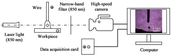
Figure 1.
Schematic diagram of the welding and high-speed camera system.
3. Experimental Procedure
The bead formation and droplet transfer are more affected by waveform parameters [25,26]. Q235, a typical mild steel, was selected by researchers to study the formation, arc behavior and droplet transfer, like Wu [15], Ghosh [27,28], and so on. In our work, 4-mm-thick mild steel (Q235) sheets were used as workpieces, whose dimensions were 150 mm × 50 mm. Thus, mild steel wire (ER50-6) with a diameter of 1.2 mm was used as the electrode wire and the CTWD (contact tube-to-work distance) was selected as 20 mm. As shielding gas, 82% Ar + 18% CO2 mixture gas with a flow rate of 15 L/min was selected. The speed of the wire feed and the speed of welding were 3 m/min and 3 mm/s, respectively. With the purpose of stable ODPP transfer, pulse current waveform showed in Figure 2 was selected according to Ref. [15]. In Figure 2, t0, t1 and t2 are the start point of the pulse peak current period, the droplet-detachment current period and the base current, respectively. Over 90% droplets are ODPP transfer at middle arc length (about 5 mm) in terms of corresponding high-speed photographs. Typical high-speed photographs of ODPP transfer mode are displayed in Figure 3.
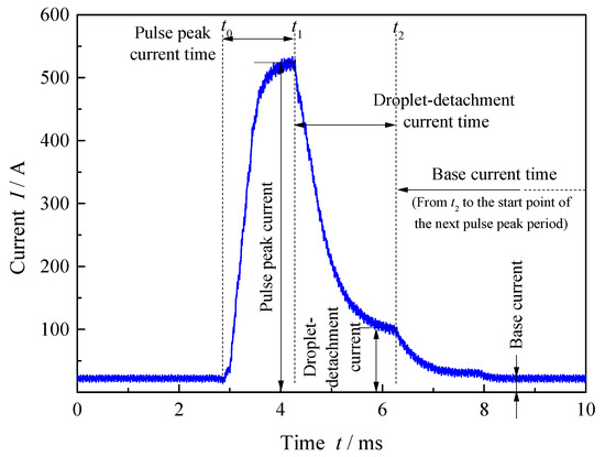
Figure 2.
Main parameters of pulse current waveform.
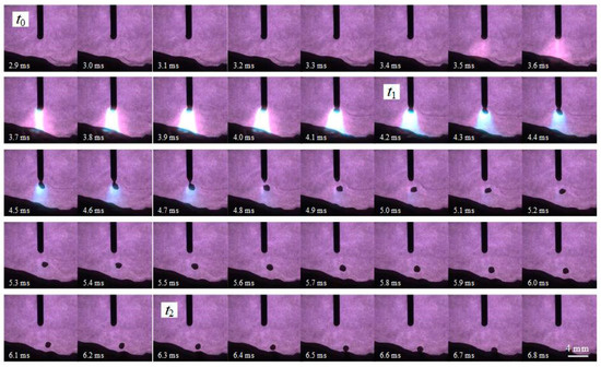
Figure 3.
Typical high-speed photographs of “one droplet per pulse” (ODPP) transfer mode.
In the high-speed camera system, in order to observe the droplet process more clearly, a narrow-band filter was used to weaken the brightness of the arc. As a result, when the current was below 300 A, the arc was almost filtered out, and was difficult to observe (see Figure 3). However, the morphology of the arc can be seen clearly with the high current and arc brightness, such as in photographs near t1. Additionally, the anode spot of arc is always over the droplet when the current is above a critical current level, so the arc length is not affected by the droplet near t1. Therefore, for the purpose of more accurate measurement, the arc length near t1 was selected to be measured in this pulse period. Then, the average arc length of a random 30 pulses is calculated as the arc length with these welding parameters.
Based on the pulse current waveform in Figure 2, the arc length was adjusted from less than 2 mm to more than 10 mm by only changing the base current time, without altering other parameters. Then, welding tests were performed on the piecework with different arc length. The parameters table of the pulse waveform and the experiment are presented in Table 1.

Table 1.
The parameters table of pulse waveform and experiment.
4. Effects of Arc Length on Welding Formation
During the welding process in Tests 1 and 2, spatters and popping noises occurred from time to time. However, if the arc length were a little longer than that in Test 2, such as in Test 3, those spatters and popping noises would disappear. By comparing the high-speed photographs, it was found that the arc lengths were longer in Tests 3–6, and droplets were all in the projected transfer mode presented in Figure 3, meaning that droplets went into the molten pool after detaching from the wire. However, the arc lengths were shorter in Tests 1 and 2. Not all droplets were in the projected transfer mode, and some short circuits were found. Therefore, in terms of the modes of droplet transfer, the tests in this experiment can be divided into “the partial projected transfer zone” (Tests 1 and 2) and “the projected transfer zone” (Tests 3–6).
4.1. The Partial Projected Transfer Zone
The welding formation of Tests 1 and 2 in the partial projected transfer zone are displayed in Figure 4. It can be seen that the surface formation of the weld bead in Test 2 was better than that in Test 1. The edge of bead was crooked, and there are lots of big spatters around the bead in Test 1. In contrast, the edge of the bead was relatively straight, and there were few big spatters in Test 2. The centerline of penetration was useful to measure, but a larger difference can be noted looking at the area of the fusion zone. Although the highlighted profile looks similar in terms of cross section formation, the weld penetration of Test 2 was only 0.1 mm deeper than that of Test 1. Moreover, from the perspective of the brown welding fumes covering the surface of the workpiece, the fumes were obviously fewer and mainly distributed within 1 cm around the weld bead in Test 2, in which the bright steel plate far away from the weld bead was clearly visible. However, the surface of the workpiece was almost covered by fumes, and the regions of bright steel plate were nearly invisible in Test 1.
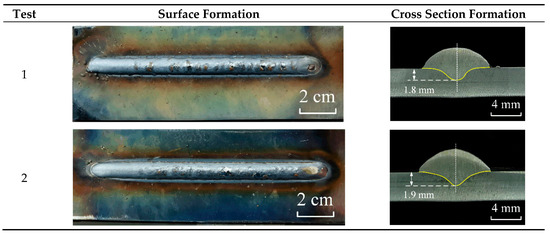
Figure 4.
The formation of the weld bead in the partial projected transfer zone.
According to the high-speed photographs of Tests 1 and 2, except for projected transfer, two types of short circuit [24] were observed: normal short circuit (see Figure 5) and instantaneous short circuit (see Figure 6). It is necessary to point out that the short circuit phenomenon in pulsed GMAW is different from that in short circuiting transfer using a constant direct-current (DC) power source. According to Ref. [29], these short circuits in pulsed GMAW, as in Figure 5b and Figure 6b, are also called meso-spray transfer. During meso-spray transfer, the position of necking is between the undetached droplet and solid wire, followed by short circuits. However, during short circuiting transfer using constant DC power source, the position of necking is at the liquid bridge, which is formed after short circuits.
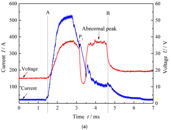
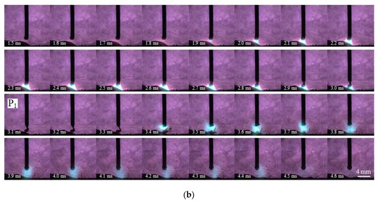
Figure 5.
The normal short circuit: (a) The welding current and voltage waveform; (b) the high-speed photographs of interval AB.
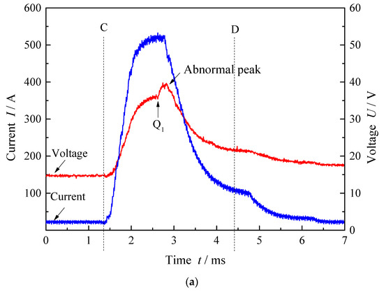
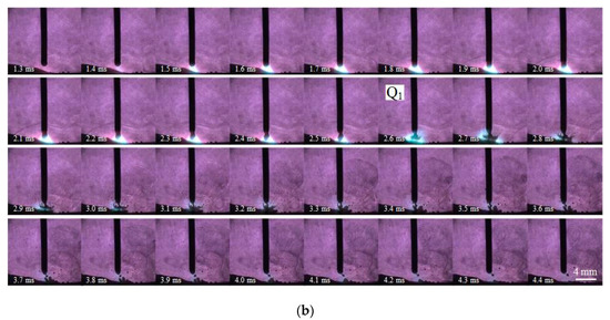
Figure 6.
The instantaneous short circuit: (a) The welding current and voltage waveform; (b) the high-speed photographs of interval CD.
During the normal short circuit (Figure 5), the neck between the undetached droplet and the wire gradually shrank, and the undetached droplet contacted the molten pool at the time P1, with a dramatic fall of voltage. Then, from the next three frames of P1 (3.1–3.3 ms), it can be seen that the bright arc was extinguished because of the short circuit and the minimum position of short circuiting liquid bridge was broken by explosion. A few spatters flied out of the explosive position, with an unstable arc and an abnormal voltage peak.
When the arc was reignited, an unstable arc and an abnormal voltage peak were found. This is because at the time of arc reignition after short circuiting, cathode spots were reformed in the center of the weld pool surface. During the process of reforming the arc and cathode spots, the concentration of the cathode spots and the increase of the cathode surface work function led to a rise in the potential gradient across the cathode fall space and the adjoining contraction space. Consequently, the arc voltage became abnormally high despite the short arc length, which can be regarded as a signal of arc reignition after short circuiting [24,30].
A similar phenomenon is also shown in Figure 6. Even though the duration of the short circuit was too short to be captured by the 10,000 fps high-speed camera, the arc behavior and the abnormal voltage peak can indicate an instantaneous short circuit at the time Q1 in Figure 6. During the process of instantaneous short circuit, the undetached droplet contacted the molten pool and was bounced off instantaneously at the time Q1. The high current near the pulse peak current leaded to huge impact force of explosion, which contributed to the split of droplet and various big spatters.
To research the cumulative effects of micro droplet transfer on macroscopic weld bead formation, the percentages of various types of droplet transfer were calculated based on each 200 pulses of Tests 1 and 2 (shown in Figure 7). Even through the average arc length in Test 1 (1.5 mm) was only 0.8 mm shorter than that in Test 2 (2.3 mm), their percentages of various types of droplet transfer were totally different. From Test 1 to Test 2, the percentage of projected transfer rise sharply from less than 10% to almost 90%. However, the proportion of the normal short circuits and the instantaneous short circuits fall from 61% and 30% to 9.5% and 2.5%, respectively. Moreover, based on the analysis of Figure 5 and Figure 6, above, a few small spatters resulted from the normal short circuits, while a large number of spatters (especially the big spatters) resulted from the instantaneous short circuits. The longer arc allowed the droplets more time to gain enough energy to fully liquefy, so that they could impact the molten pool without short circuiting and causing explosions. Therefore, spatters declined obviously when the arc length grew a little from Test 1 to Test 2.
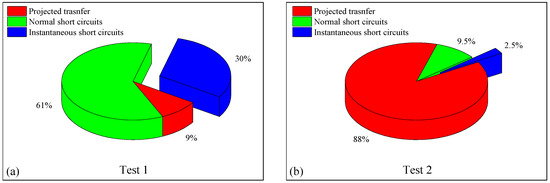
Figure 7.
The percentages of various types of droplet transfer in the partial projected transfer zone: (a) Test 1; (b) Test 2.
4.2. The Projected Transfer Zone
If the arc length were long enough, the droplets would have enough space to drop into the molten pool after detaching from the wire. As a result, short circuits would disappear, and all the droplets would come into the projected transfer zone. The welding formations of Tests 3–6 in the projected transfer zone are displayed in Figure 8. As the arc length increased, the surface formation gradually deteriorated. The specific performances are as follows: the surfaces of Tests 3 and 4 were relatively straight and beautiful. The bead of Test 5 was generally smooth, but the edges of the bead were slightly crooked, with about a 1 mm offset. The surface formation of Test 6 is pretty poor. It can be clearly seen in Test 6 that the bead was uneven, and the edges were severely twisted, being visibly asymmetrical. Dozens of droplets dropped directly outside the molten pool and became large spatters near the bead. In addition, from the perspective of the brown welding fumes covered on the surface of the workpiece, the fumes were almost parallel to the bead on both sides. As the arc grew, there were more and wider fumes.
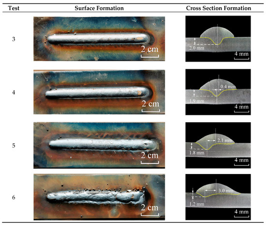
Figure 8.
The formation of weld bead in the projected transfer zone.
The relationship of arc length and parameters of cross section formation in the projected transfer zone is shown in Figure 9. With the increase in arc length, the penetration depth and weld reinforcement declined marginally, whereas the weld width rose a little. The greater spread of the plasma arc can cause the energy to be dispersed over a larger area. Figure 10 is the gray-scale image (256 levels) of long and short arc morphology captured at the same peak current time. The average gray levels of arc near molten pool (box region) in Figure 10a,b were 254.82 and 223.25, respectively. As we know, the higher the gray level is, the higher the arc brightness is, and the higher the current density is. Therefore, the current density of shorter arc near molten pool in Figure 10a was higher than that of the longer arc in Figure 10b. It can be also seen in Figure 10 that the arc width will increase with the increase of arc length, and the arc will be more dispersed, contributing to the expansion of heat source radius and heat dissipation of arc. As a result, the penetration depth declined and weld width rise. Additionally, because the speed of wire feed and welding are constant, weld reinforcement declined with the wider weld width.
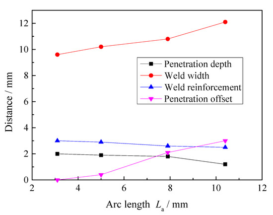
Figure 9.
The relationship of arc length and parameters of cross section formation in the projected transfer zone.
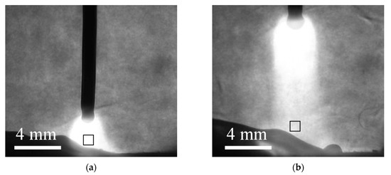
Figure 10.
The gray-scale images of short and long arc morphology captured at the same peak current time: (a) Test 3; (b) Test 6.
Moreover, in Figure 8, the offset between the deepest point of penetration and the center of weld bead (penetration offset for short) significantly increased with the growth of arc length. The wire was not completely straight when fed out from the contact tube, because it was bent into a disc shape before welding for convenience of transportation and storage. Additionally, during real welding operation, wire inevitably inclines to a certain extent, which is not completely perpendicular to the plane of the workpiece. The end of the wire might be perpendicular to the workpiece, but the inclination of wire would increase with the growth of arc length. In addition, the droplets tend to move along the axis of welding wire in the projected transfer [23]. Therefore, the direction of droplet movement cannot be completely perpendicular to the plane of the workpiece. The rise of arc length increased the distance between wire tip and molten pool. Under the same transverse velocity, droplets could deviate from the center of the weld bead more greatly with the longer arc. Since the heat and mass carried by the droplets deviated from the center were transferred to the molten pool on one side, and the increasing magnetic fields generated by the plasma column likely caused rotation, contributing to an asymmetric driving force within the molten pool, the symmetry of penetration was broken, eventually leading to penetration offset. A similar phenomenon was also observed in Ref. [31]. A more serious deviation of the droplets and a greater penetration offset would be obtained with a longer arc length. Overall, a phenomenon was observed whereby the penetration offset in pulsed GMAW became more sensitive with the increase of arc length.
5. Effects of Arc Length on Droplet Transfer
There are three types of projected transfer in pulse GMAW: “multiple drops per pulse” (MDPP), “one drop per pulse” (ODPP), and “one drop per multiple pulses” (ODMP). ODPP was recognized as the most ideal transfer mode, and was mainly affected by the pulse peak current (Ip) and time (tp), but not base time (tb), by many researchers [13,14,15]. In addition, tb was believed to be a parameter for adjusting the arc length. However, in this work, when Ip and tp were fixed, it was found that the arc length had crucial effects on droplet transfer as well as the droplet impact force by only changing tb.
5.1. The Effects of Arc Length on the Types of Projected Transfer
By observing the high-speed photographs of different tests in Figure 11, even if the parameters of the current waveform remained unchanged, the droplets did not belong 100% to ODPP. The mixture of MDPP and ODPP was displayed in Test 3 and Test 4, but no ODMP was found. In Test 5 and Test 6, the mixture of ODPP and ODMP replaced the mixture of MDPP and ODPP, and MDPP was no longer to be seen. Additionally, most of the droplets were in the form of one big droplet and one small droplet in the MDPP, as shown in Figure 11a,b. The diameter of the big droplet in the MDPP was similar to the droplet in the ODPP, but those droplets were smaller than that in the ODMP.
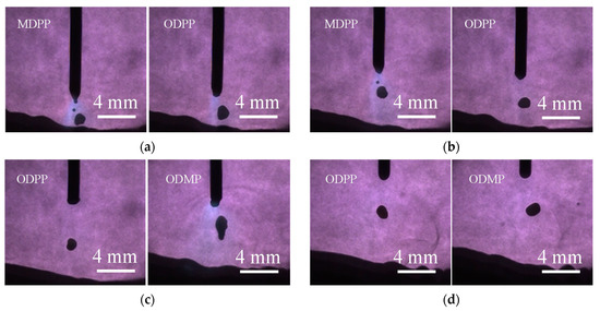
Figure 11.
The typical droplet morphology of different types of projected transfer: (a) Test 3; (b) Test 4; (c) Test 5; (d) Test 6.
The three types of projected transfer were calculated based on 200 pulses in each test, and the statistical data is shown in Figure 12. The Y-axis φ in Figure 12 is the percentage of the pulses’ number, rather than the percentage of the droplets’ number. It can be found that ODPP was the main mode for each test. The proportion of ODPP of Test 4 was the highest in these tests, and was over 95%. However, ODPP occupied the least in Test 6 (less than 70%). The arc length grew gradually from Test 3 to Test 6. In terms of whole tendency, the short arc trended to rise the proportion of MDPP, but the long arc trended to rise the proportion of ODMP. According to the Static Force Balance Theory [32], the detaching force is the sum of the electromagnetic force (Fem), the gravitational force (Fg), and the plasma drag force (Fd), while the retaining force (Fγ) is the surface tension. As described in Section 4.2, the arc would be more dispersed with the growth of length, contributing to the expansion of heat source radius and heat dissipation. Thus, when the peak energy of a single pulse current was fixed, the smaller detaching force was obtained by a single droplet with the long arc. Consequently, more pulses were needed to increase the detaching force and help the droplet to detach from wire. Because the droplet size was bigger and the gravitational force grew, which contributes to ODMP process and vice versa. However, due to the suitable arc length in Test 4, the appropriate detaching arc force was matched with the ODPP condition and the highest proportion of ODPP was observed.
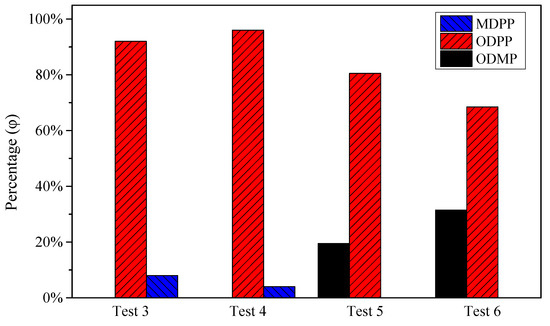
Figure 12.
The statistical data of the three types of projected transfer.
5.2. The Effects of Arc Length on the Droplet Impact Force
The droplet impact force is the cumulative effect of droplets. If the types of droplet transfer were changed, the droplet impact force would be different as well [33]. According to Ref. [34], the droplet was considered approximately to be a sphere and the droplet impact force (Pd) was regarded as a force per unit area or pressure, which was relative to the droplet mass (md), velocity (vd), frequency (fd) and diameter (dd), as displayed in Equation (1).
According to the mass formula of the sphere, the md can be calculated by Equation (2).
Therefore, Equation (1) can be further written as Equation (3) (density ρ = 7.8 g/cm3).
However, Equation (3) is only applicable to the single-mode droplet transfer. For the mixture of different types of projected transfer, the droplet impact force should be the sum of each droplet impact force in MDPP, ODPP and ODMP (Equation (4)).
The droplet frequency of MDPP, ODPP and ODMP are noted as , and , while the percentage of the pulses’ number are noted as , and respectively. Therefore, the droplet frequency of ODPP equals the percentage of the pulses’ number (φ) times the frequency of pulse current wave (f) (Equation (5)).
In addition, the frequency of the big droplet and the small droplet in MDPP (see Figure 11) are equal to the frequency of current pulses (Equation (6)). Multiple sized droplets can be found in the MDPP process, but the biggest droplet was much larger than the others (see Figure 11). Thus, the droplet impact force was approximately regarded as that of the biggest droplets in MDPP process.
In the ODMP process, a droplet may detach from the wire after severe pulses. After observation and calculation from the high-speed photographs, the average pulses for every MDPP are 2.2 and 2.3 in Test 5 and Test 6, respectively. Thus, the droplet frequency in Test 5 and Test 6 can be calculated by Equations (7) and (8).
Moreover, the percentage of the pulses’ number (φ) and the frequency of pulse current wave (f) can be read from Figure 12 and Table 1, respectively. The image-processing method in Ref. [35] was used to estimate the droplet velocity (vd) and diameter (dd). By using Equations (1)–(8) simultaneously, the average droplet impact force of each test was obtained in Figure 13. It can be seen that the droplet impact force of Test 3 was the highest, while the droplet impact force of Test 6 is the lowest. The former was about 50% larger than the latter, indicating that the arc length has an important influence on the droplet impact force. The droplet impact force declined with the growth of the arc length. In addition, the main part of the droplet impact force was contributed from ODPP.
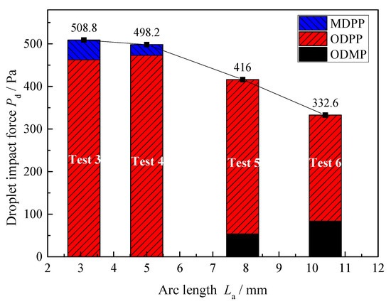
Figure 13.
The average droplet impact force of projected transfer.
6. Discussion
The characteristics of weld bead formation and droplet transfer in pulsed GMAW with different arc lengths (about 1–11 mm) by changing the base current time were studied in this work. Because enough arc space was needed when a droplet detached from the wire and dropped into the molten pool, the mixture of projected transfer and short circuits would be obtained if the arc length were shorter than 3 mm. However, spatters would inevitably be produced from short circuits, especially instantaneous short circuits (Section 4.1). To reduce the spatters and improve the weld bead formation, the shortest arc is recommended to be limited to avoid the partial projected transfer zone.
Additionally, in the projected transfer zone, the quality of weld bead surface formation became worse gradually with the increase of the arc length. When the arc length was over 10 mm, dozens of droplets directly dropped outside the molten pool and became large spatters near the bead (Section 4.2). In addition, the penetration offset in pulsed GMAW will become more sensitive with the increase of arc length. The penetration offset was less than 0.5 mm when the arc length was no more than 5 mm. However, when the arc length exceeded 10 mm, the penetration offset can reach 3 mm, which is not conducive to the positioning and alignment of the bead.
On one hand, Figure 10 in Section 4.2 indicates that the increase of arc length contributes to the fall of energy density and increase of heat dissipation of arc. On the other hand, Figure 13 in Section 5.2 implies that the droplet impact force declined with the growth of the arc length. According to Ref. [34], large droplet impact force can promote the increase of weld penetration. Therefore, because of the above three factors (the increase of arc heat dissipation, the fall of arc energy density and droplet impact force), the penetration tended to become shallower.
As a result, it is suggested that the arc length should be limited to a shorter range (less than 5 mm) in the projected transfer zone. So that the welding formation can be improved, the penetration offset can be reduced and the larger penetration can be obtained. Additionally, Table 1 shows that the average current of shorter arc was smaller, which can reduce heat input and save electric energy when compared with the longer arc.
In our preliminary experiment, the tensile properties of welded joints were also affected under difference arc lengths. According to AWS: B4 specifications [36], the tensile test specimens were prepared from the butt joints in the perpendicular direction to the welded seam. Figure 14 shows the average tensile strengths and elongations of the welded joints with different arc lengths in the projected transfer zone. It can be seen that the tensile strengths were approximately constant. However, with the growth of arc length, the elongations fell gradually. This implied that the short arc is also beneficial for obtaining weld joints with high elongations.
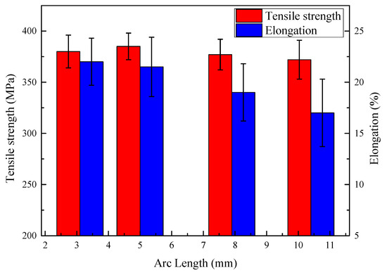
Figure 14.
The tensile strengths and elongations of the welded joints with different arc lengths in the projected transfer zone.
In addition to the above discussion, the power law relationship () has been used in many studies to determine the peak current and time of ODPP transfer mode [16,17,18], ignoring the influence of the base current time. However, in this work, it was found that the types of droplet transfer in pulsed GMAW changed a lot by only adjusting the base current time, even though the peak current and time were constant. More than 90% (but not 100%) ODPP transfer mode can be obtained when the pulse parameters were selected properly. The arc length can be adjusted by the base current time. The short arc trended to rise the proportion of MDPP, and the long arc trended to rise the proportion of ODMP.
7. Conclusions
(1) The arc length plays a crucial role in the quality of weld bead formation. In this work, the partial projected transfer zone can be obtained in pulsed GMAW when the arc length was shorter than 3 mm, resulting in the increasement of instantaneous short circuits and inevitable spatters. However, when arc length became longer than 5 mm in the projected transfer zone, the asymmetry and offset of penetration can be enlarged a lot.
(2) For the purpose of obtaining high-quality weld bead formation and weld joints, a shorter arc in the projected transfer zone was recommended. However, the partial projected transfer zone should be avoided when the arc length was short, in order to reduce unnecessary spatters. For example, for the ER50-6 wire with diameter of 1.2 mm used in this work, the appropriate arc length was about 3–5 mm. The base current time should be adjusted according to the appropriate arc length range.
(3) Peak current and peak current time are not were parameters that determine ODPP transfer mode in pulsed GMAW, which was also affected by the arc length. More than 90% (but not 100%) ODPP transfer mode can be obtained when the pulse parameters were selected properly. The short arc trended to rise the proportion of MDPP, and the long arc trended to rise the proportion of ODMP.
(4) The droplet impact force with different arc lengths in the projected transfer zone was calculated. The droplet impact force declined with the growth of the arc length. The increase of arc heat dissipation, the fall of arc energy density, and droplet impact force contributed to the result in that the penetration tended to become shallower in the projected transfer zone.
Author Contributions
Methodology, P.Z.; software, P.Z. and J.W.; investigation, P.Z., W.C., T.C., and S.J.; writing—original draft preparation, P.Z.; writing—review and editing, S.X. and P.Z.; supervision, S.X.; project administration, S.X.; funding acquisition, S.X. All authors have read and agreed to the published version of the manuscript.
Funding
This work was funded by the National Natural Science Foundation of China, grant No. 51675269 and the Priority Academic Program Development of Jiangsu Higher Education Institutions (PAPD).
Conflicts of Interest
The authors declare no conflict of interest.
References
- Pépe, N.; Egerland, S.; Colegrove, P.A.; Yapp, D.; Leonhartsberger, A.; Scotti, A. Measuring the Process Efficiency of Controlled Gas Metal Arc Welding Processes. Sci. Technol. Weld. Join. 2011, 16, 412–417. [Google Scholar] [CrossRef]
- Rout, A.; Deepak, B.B.V.L.; Biswal, B.B. Advances in Weld Seam Tracking Techniques for Robotic Welding: A Weview. Robot. Comput. Integr. Manuf. 2019, 56, 12–37. [Google Scholar] [CrossRef]
- Praveen, P.; Yarlagadda, P.K.D.V.; Kang, M.J. Advancements in Pulse Gas Metal Arc Welding. J. Mater. Process. Technol. 2005, 164–165, 1113–1119. [Google Scholar] [CrossRef]
- Huang, L.; Hua, X.; Wu, D.; Jiang, Z.; Li, F.; Wang, H.; Shi, S. Microstructural Characterization of 5083 Aluminum Alloy Thick Plates Welded with GMAW and Twin Wire GMAW Processes. Int. J. Adv. Manuf. Technol. 2017, 93, 1809–1817. [Google Scholar] [CrossRef]
- Oliveira, J.P.; Barbosa, D.; Fernandes, F.M.B.; Miranda, R.M. Tungsten Inert Gas (TIG) Welding of Ni-rich NiTi Plates: Functional Behavior. Smart Mater. Struct. 2016, 25, 3. [Google Scholar] [CrossRef]
- Oliveira, J.P.; Crispim, B.; Zeng, Z.; Omori, T.; Braz Fernandes, F.M.; Miranda, R.M. Microstructure and Mechanical Properties of Gas Tungsten Arc Welded Cu-Al-Mn Shape Memory Alloy Rods. J. Mater. Process. Technol. 2019, 271, 93–100. [Google Scholar] [CrossRef]
- Oliveira, J.P.; Curado, T.M.; Zeng, Z.; Lopes, J.G.; Rossinyol, E.; Park, J.M.; Schell, N.; Braz Fernandes, F.M.; Kim, H.S. Gas Tungsten Arc Welding of as-rolled CrMnFeCoNi High Entropy Alloy. Mater. Des. 2020, 189, 108505. [Google Scholar] [CrossRef]
- Pan, M.; Linner, T.; Pan, W.; Cheng, H.; Bock, T. A Framework of Indicators for Assessing Construction Automation and Robotics in the Sustainability Context. J. Clean. Prod. 2018, 182, 82–95. [Google Scholar] [CrossRef]
- David, S.A.; Chen, J.; Gibson, B.T.; Feng, Z. Intelligent Weld Manufacturing: Role of Integrated Computational Welding Engineering. In Transactions on Intelligent Welding Manufacturing; Chen, S., Zhang, Y., Feng, Z., Eds.; Springer Singapore: Singapore, 2018; Volume 1, pp. 3–30. [Google Scholar]
- Xu, Y.; Fang, G.; Lv, N.; Chen, S.; Zou, J.J. Computer Vision Technology for Seam Tracking in Robotic GTAW and GMAW. Robot. Comput. Integr. Manuf. 2015, 32, 25–36. [Google Scholar] [CrossRef]
- Xu, Y.; Lv, N.; Fang, G.; Du, S.; Zhao, W.; Ye, Z.; Chen, S. Welding Seam Tracking in Robotic Gas Metal Arc Welding. J. Mater. Process. Technol. 2017, 248, 18–30. [Google Scholar] [CrossRef]
- Kozakov, R.; Gött, G.; Schöpp, H.; Uhrlandt, D.; Schnick, M.; Häßler, M.; Füssel, U.; Rose, S. Spatial Structure of the Arc in a Pulsed GMAW Process. J. Phys. D Appl. Phys. 2013, 46, 224001. [Google Scholar] [CrossRef]
- Pal, K.; Pal, S.K. Effect of Pulse Parameters on Weld Quality in Pulsed Gas Metal Arc Welding: A Review. J. Mater. Eng. Perform. 2011, 20, 918–931. [Google Scholar] [CrossRef]
- Ghosh, P.K.; Goyal, V.K.; Dhiman, H.K.; Kumar, M. Thermal and Metal Transfer Behaviours in Pulsed Current Gas Metal Arc Weld Deposition of Al–Mg Alloy. Sci. Technol. Weld. Join. 2006, 11, 232–242. [Google Scholar] [CrossRef]
- Wu, C.S.; Chen, M.A.; Lu, Y.F. Effect of Current Waveforms on Metal Transfer in Pulsed Gas Metal Arc Welding. Meas. Sci. Technol. 2005, 16, 2459–2465. [Google Scholar] [CrossRef]
- Amin, M. Pulse Current Parameters for Arc Stability and Controlled Metal Transfer in Arc Welding. Metal Constr. 1983, 15, 272–278. [Google Scholar]
- Rajasekaran, S. Weld Bead Characteristics in Pulsed GMA Welding of AI-Mg Alloys. Weld. J. 1999, 78, 397s–407s. [Google Scholar]
- Rajasekaran, S.; Kulkarni, S.D.; Mallya, U.D.; Chaturvedi, R.C. Droplet Detachment and Plate Fusion Characteristics in Pulsed Current Gas Metal Arc Welding. Weld. J. 1998, 77, 254s–269s. [Google Scholar]
- Pinchuk, I. Stabilization of Transfer and Methods of Reducing the Spattering of Metal in CO2 Welding with a Short Arc. Weld. Res. Abroad 1982, 33–35. [Google Scholar]
- Kang, M.J.; Kim, Y.; Ahn, S.; Rhee, S. Spatter Rate Estimation in the Short Circuit Transfer Region of GMAW. Weld. J. 2003, 82, 238s–247s. [Google Scholar]
- Harwig, D.D.; Dierksheide, J.E.; Yapp, D.; Blackman, S. Arc Behavior and Melting Rate in the VP-GMAW Process. Weld. J. 2006, 85, 52s–62s. [Google Scholar]
- Hertel, M.; Rose, S.; Füssel, U. Numerical Simulation of Arc and Droplet Transfer in Pulsed GMAW of Mild Steel in Argon. Weld. World 2016, 60, 1055–1061. [Google Scholar] [CrossRef]
- Chen, C.; Fan, C.; Cai, X.; Lin, S.; Yang, C. Analysis of Droplet Transfer, Weld Formation and Microstructure in Al-Cu Alloy Bead Welding Joint with Pulsed Ultrasonic-GMAW Method. J. Mater. Process. Technol. 2019, 271, 144–151. [Google Scholar] [CrossRef]
- Tong, H.; Ueyama, T.; Tanaka, M.; Ushio, M. Observations of the Phenomenon of Abnormal Arc Voltage Occurring in Pulsed Metal Inert Gas Welding of Aluminum Alloy. Sci. Technol. Weld. Join. 2005, 10, 695–700. [Google Scholar] [CrossRef]
- Joseph, A.; Farson, D.; Harwig, D.; Richardson, R. Influence of GMAW-P Current Waveforms on Heat Input and Weld Bead Shape. Sci. Technol. Weld. Join. 2013, 10, 311–318. [Google Scholar] [CrossRef]
- Palani, P.K.; Murugan, N. Selection of Parameters of Pulsed Current Gas Metal Arc Welding. J. Mater. Process. Technol. 2006, 172, 1–10. [Google Scholar] [CrossRef]
- Ghosh, P.K.; Dorn, L.; Devakumaran, K.; Hofmann, F. Pulsed Current Gas Metal Arc Welding under Different Shielding and Pulse Parameters; Part 1: Arc Characteristics. ISIJ Int. 2009, 49, 251–260. [Google Scholar] [CrossRef]
- Ghosh, P.K.; Dorn, L.; Devakumaran, K.; Hofmann, F. Pulsed Current Gas Metal Arc Welding under Different Shielding and Pulse Parameters; Part 2: Behaviour of Metal Transfer. ISIJ Int. 2009, 49, 261–269. [Google Scholar] [CrossRef][Green Version]
- Li, Z.; Wang, Y.; Yang, L.; Li, H. Meso Spray Transfer in GMAW of Aluminum and its Control. In Proceedings of the 2009 4th IEEE Conference on Industrial Electronics and Applications, Xi’an, China, 25–27 May 2009; pp. 3148–3151. [Google Scholar]
- Choi, J.H.; Lee, J.Y.; Yoo, C.D. Simulation of Dynamic Behavior in a GMAW System. Weld. J. 2001, 80, 239s–246s. [Google Scholar]
- Zhang, Z.; Xue, J.; Jin, L.; Wu, W. Effect of Droplet Impingement on the Weld Profile and Grain Morphology in the Welding of Aluminum Alloys. Appl. Sci. 2018, 8, 1203. [Google Scholar] [CrossRef]
- Kim, Y.S.; Eagar, T.W. Analysis of Metal Transfer in Gas Metal Arc Welding. Weld. J. 1993, 72, 269s–278s. [Google Scholar]
- Zhu, F.L.; Tsai, H.L.; Marin, S.P.; Wang, P.C. A Comprehensive Model on the Transport Phenomena during Gas Metal Arc Welding Process. Prog. Comput. Fluid Dyn. 2004, 4, 99–117. [Google Scholar] [CrossRef]
- Wu, C.; Dorn, L. The Influence of Droplet Impact on Metal Inert Gas Weld Pool Geometry. Acta Metall. Sin. 1997, 33, 774–780. [Google Scholar]
- Zhai, P.; Xue, S.; Chen, T.; Wang, J.; Tao, Y. An Image-Processing Method for Extracting Kinematic Characteristics of Droplets during Pulsed GMAW. Appl. Sci. 2019, 9, 5481. [Google Scholar] [CrossRef]
- Mirzaei, M.; Arabi Jeshvaghani, R.; Yazdipour, A.; Zangeneh-Madar, K. Study of Welding Velocity and Pulse Frequency on Microstructure and Mechanical Properties of Pulsed Gas Metal Arc Welded High Strength low Slloy Steel. Mater. Des. 2013, 51, 709–713. [Google Scholar] [CrossRef]
© 2020 by the authors. Licensee MDPI, Basel, Switzerland. This article is an open access article distributed under the terms and conditions of the Creative Commons Attribution (CC BY) license (http://creativecommons.org/licenses/by/4.0/).