Abstract
Uniaxial static and cyclic creep tests were carried out on bainite 2.25Cr-1Mo steel at 455 °C. Effects of the unloading rate from 0.6 to 39 MPa/s and valley stress duration from 0 to 30 min on the cyclic creep deformation behavior were discussed. The results indicated that the fracture behavior under static and cyclic creep conditions showed a consistent ductile mode. The strain accumulation rate under cyclic creep was significantly retarded as compared with static creep due to the presence of anelastic recovery which was apparently influenced by the unloading conditions. For cyclic creep tests, the unrecoverable strain component determined by a systematic classification of the stress–strain curve was the true damage. A modified life prediction method proposed based on the unrecoverable strain component presented a good life prediction for cyclic creep.
1. Introduction
Many engineering structures and components are frequently subjected to cyclic loadings during normal operation, which generally leads to a complicated failure mechanism caused by a combined damage mode of creep, fatigue, and their interactions [1,2,3,4,5]. Especially, stress loading is more common in practical engineering applications than strain loading [6]. Cyclic creep commonly refers to the progressive change of mean strain during the cyclic plastic deformation under a creep test with cyclic stress loading, which belongs to creep–fatigue interactive behavior [7]. Therefore, the cyclic creep response of materials should be an essential consideration for the component design.
The strain accumulation for cyclic creep is usually time-dependent which is similar to ratcheting [8,9]. The ratcheting strain rate can be greatly influenced by a series of test parameters such as stress amplitude, stress ratio, and duration under hold stress. With the increase in duration under peak stress, a transition in dominant damage type from fatigue to creep can be found, and similarly, the fracture mode transformed from a brittle to ductile failure [10]. Moreover, the study of 9–12% Cr steel showed that the strain rate in cyclic creep was between that under ratcheting fatigue and static creep, i.e., the creep damage was more pronounced than the fatigue damage and the static creep rate determined the upper rate of the cyclic creep [11]. Similar performances can be found in some nickel-based alloys such as GH720Li alloy [12] and MA754 alloy [13]. However, research on the cyclic creep response of a nickel-based super alloy, DZ125, under different gradients of stress amplitudes and temperatures showed that cyclic creep accelerated the strain accumulation rate compared to static creep. The fatigue rate without a peak stress hold was reported to be the upper rate of the cyclic creep [14]. Other cases where fatigue damage dominated could be found on pure metal copper [15] and AMg6 alloy [16]. In addition, a material could yield opposite results at different temperatures such as Cr-Mo-V steel, which was observed to undergo cyclic creep rate acceleration at room temperature and cyclic creep rate retardation at 550 °C [17]. Therefore, cyclic creep performances deserve more research attention, and the underlying deformation mechanism should be further studied.
For the cases of cyclic creep rate retardation, the anelasticity produced during unloading is the main reason for the retarding strain accumulation. Anelasticity occurs when a material undergoes a sudden change in unloading and requires time to attain a new equilibrium configuration [18]. Anelastic recovery behavior is related to the reversible time-dependent dislocation motion essentially, and the motion is driven by back stress [19]. In recent research on 9–12% Cr steel, the bowing of the pined dislocation was observed by transmission electron microscope (TEM) and the magnitude of anelastic strain during different valley stress holding stages was obtained. It indicated that the displacement of the dislocation motion was influenced by stress amplitudes, stress ratios, and peak stress durations, and caused differences in anelastic recovery responses [20]. Moreover, a simplified model for the dislocation motion based on the effective stress concept was proposed to explain the anelastic recovery behavior [21].
2.25Cr-1Mo steel has been extensively used in pressure vessels and pipeline systems in petroleum and power industries owing to its good mechanical properties at elevated temperatures [22]. The mechanical behavior of 2.25Cr-1Mo steel under static creep, low-cycle fatigue, and creep–fatigue interaction conditions has been studied by Klueh [23], Jaske [24], and Challenger et al. [25]. A series of life predication methods was proposed to adapt various experiments. However, most of the methods for cyclic life were generally used for strain-controlled tests, e.g., an energy-based method for the low-cycle fatigue behavior of 2.25Cr-1Mo steel at elevated temperature had been reported by Callaghan et al. [26] and Zhang et al. [27]. Although large amounts of experimental data are available on the creep–fatigue interaction of 2.25Cr-lMo steel, it should be noted that a research work on cyclic creep under stress control considering the anelastic behavior of 2.25Cr-1Mo steel has not been reported.
In this study, a series of uniaxial cyclic creep tests under stress-controlled mode on bainite 2.25Cr-1Mo steel at 455 °C in air were conducted. The strain accumulation processes under different unloading conditions were analyzed through the strain classification. Specific attention was paid to the effect of the unloading rate and valley stress duration on the anelastic recovery behavior. Moreover, scanning electron microscopy (SEM) observations of fracture surfaces were performed. The goal of the current study is to identify the failure mechanism of static creep and cyclic creep on 2.25Cr-1Mo steel at high temperature and propose a modified life prediction method for cyclic creep considering anelastic recovery.
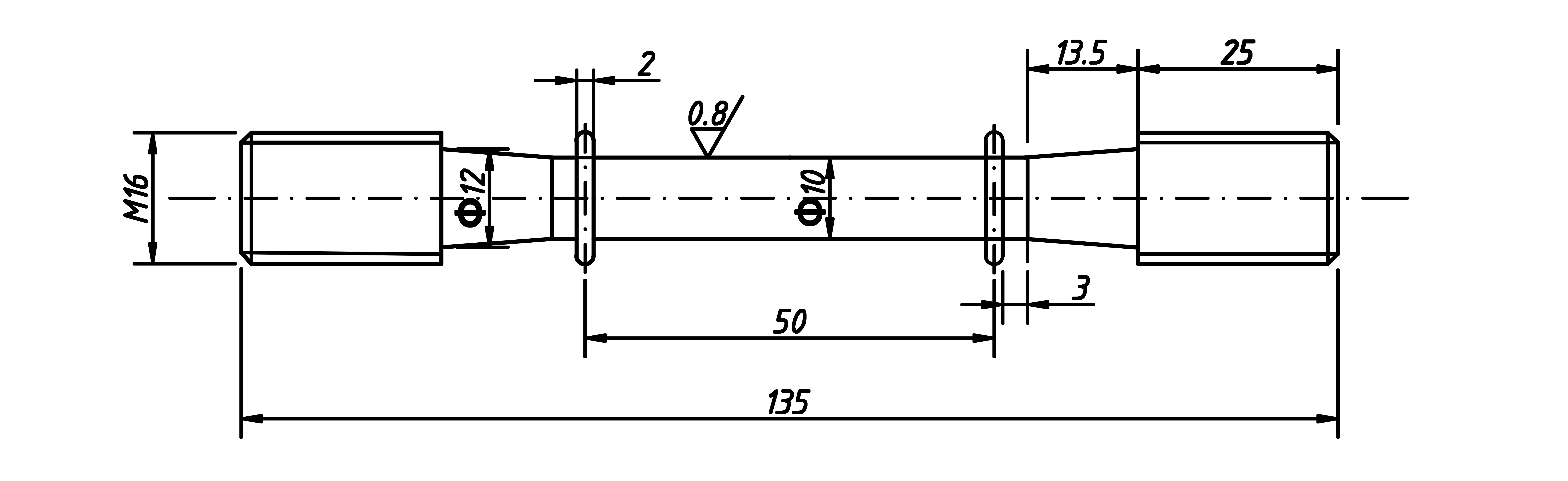
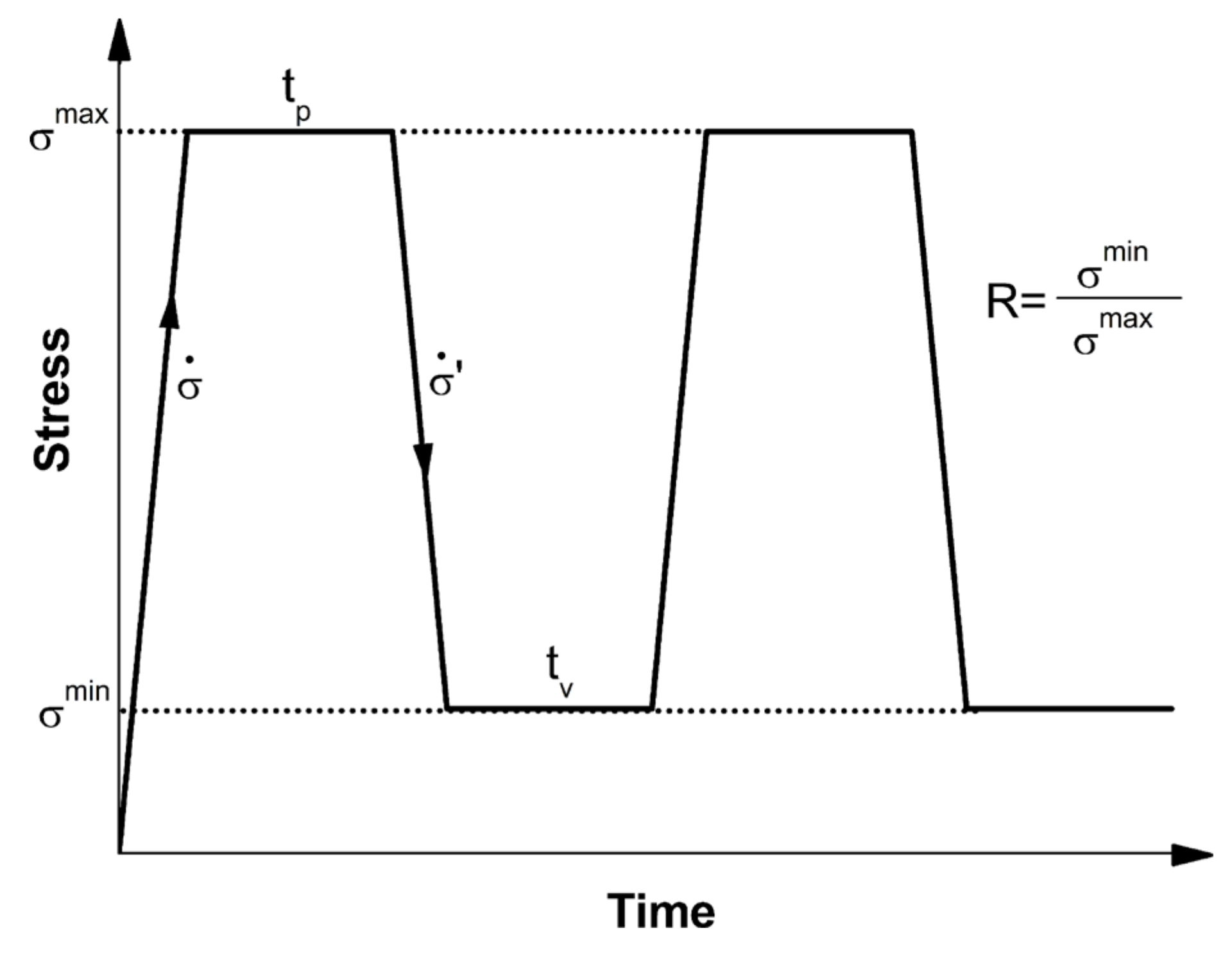
2. Materials and Methods
The material used for this present study is bainite 2.25Cr-1Mo steel. The chemical composition of the steel is shown in Table 1 and the tensile properties are shown in Table 2, where , , , , and are temperature, 0.2% proof stress, ultimate tensile strength, elongation, and reduction in area, respectively. The material was machined into a cylindrical test specimen for static creep and cyclic creep tests, with a diameter of 10 mm and a gauge length of 50 mm. The standard used in this work for the specimen machining and creep tests preformation is ISO 204;2009. The dimension specification is shown in Figure 1.
Table 1.
The nominal chemical composition of 2.25Cr-1Mo steel (in wt %).
Table 2.
Monotonic tensile properties of 2.25Cr1Mo steel.
Figure 1.
The dimension specification of test specimen (in mm).
Uniaxial static creep and cyclic creep tests were carried out on an electronic creep testing machine RD-50 (GUANTENG automation Inc., Changchun, China). The module of the electronic creep testing machine mainly includes a high-temperature heating furnace, three K-type thermocouples, and heat-resistant rail-type extensometers. The temperature was held within a fluctuation of ±1 °C. The deformations recorded on the gauge section of the specimen were measured with an accuracy of 1 μm. Three K-type thermocouples were uniformly distributed along the gauge section of the tested specimen. The testing temperature was selected as 455 °C which is the service temperature of the catalyst discharge tank. A total of 30 min was held before loading to obtain a uniform temperature distribution within the specimen gauge section.
For the purpose of studying the effect of the unloading condition on the cyclic creep behavior and anelastic recovery response, a uniaxial pulsating tension–tension wave was applied under stress control as shown in Figure 2, where and are the durations imposed at peak and valley stresses. and are the stress rates of loading and unloading. The peak stress and stress ratio R were constants, which were 400 MPa and 0.0375, respectively. The loading condition was fixed at a loading rate of 12 MPa/s with a duration of 60 min. Moreover, various unloading conditions were applied with being 0.6, 12, 19, and 39 MPa/s and being 0, 10, and 30 min. The static creep test under 400 MPa was also performed as a comparison. All specimens were tested until fracture. Moreover, all the fractographic observations were carried out on the Hitachi s-4800 High resolution SEM (HITACHI, Tokyo, Japan). The SEM investigations during the observation of the fracture surface were all conducted using a 15 kV acceleration voltage and 10 mm working distance.
Figure 2.
Pulsating wave under stress control.
3. Results and Discussion
All the test results are summarized in Table 3, where the endurance life refers to the total duration under peak stress, i.e., the loading time, and the unloading time and valley stress duration are not included.
Table 3.
Summary of test results at 455 °C ( = 400 MPa, R = 0.0375).
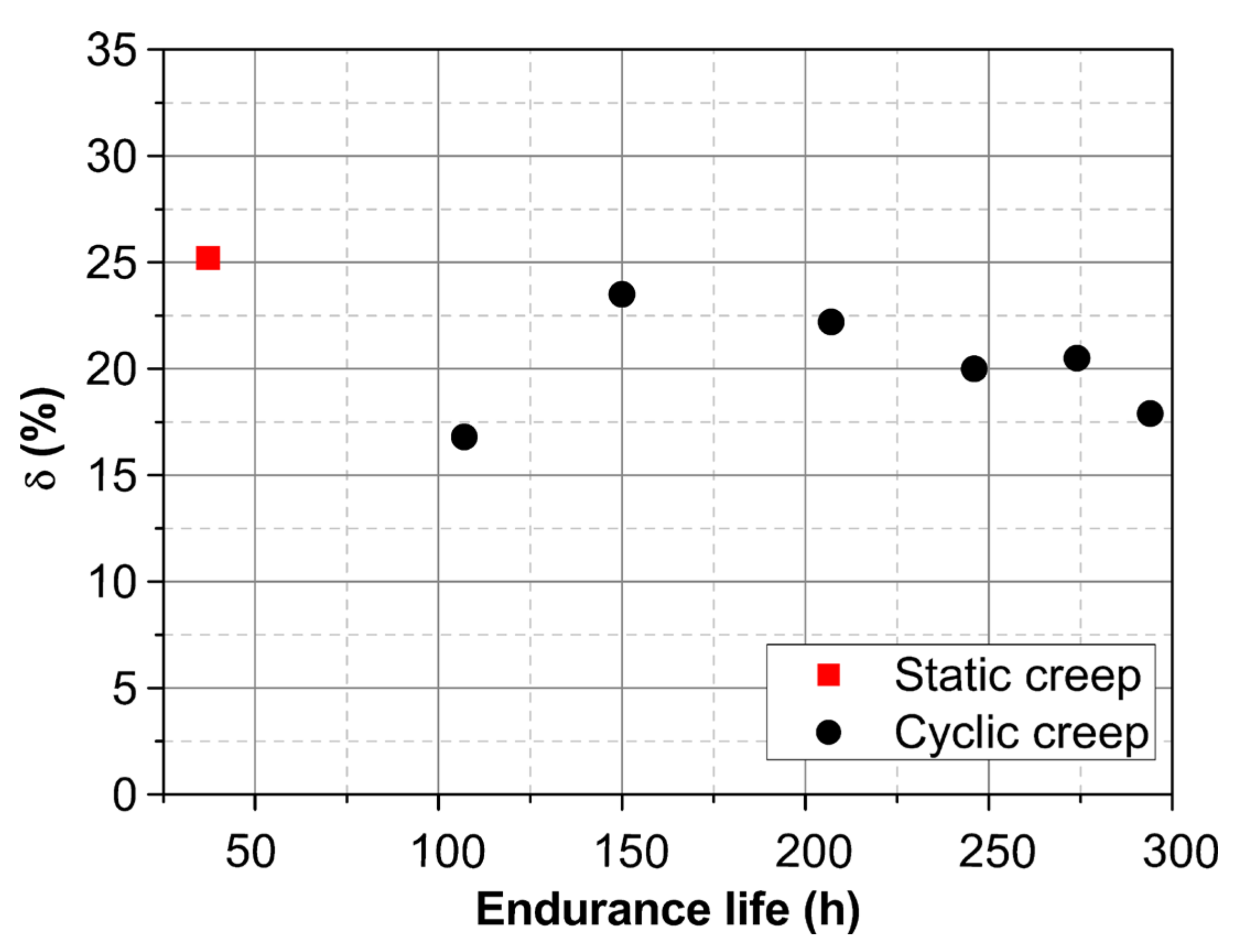
3.1. Cyclic Creep Behavior
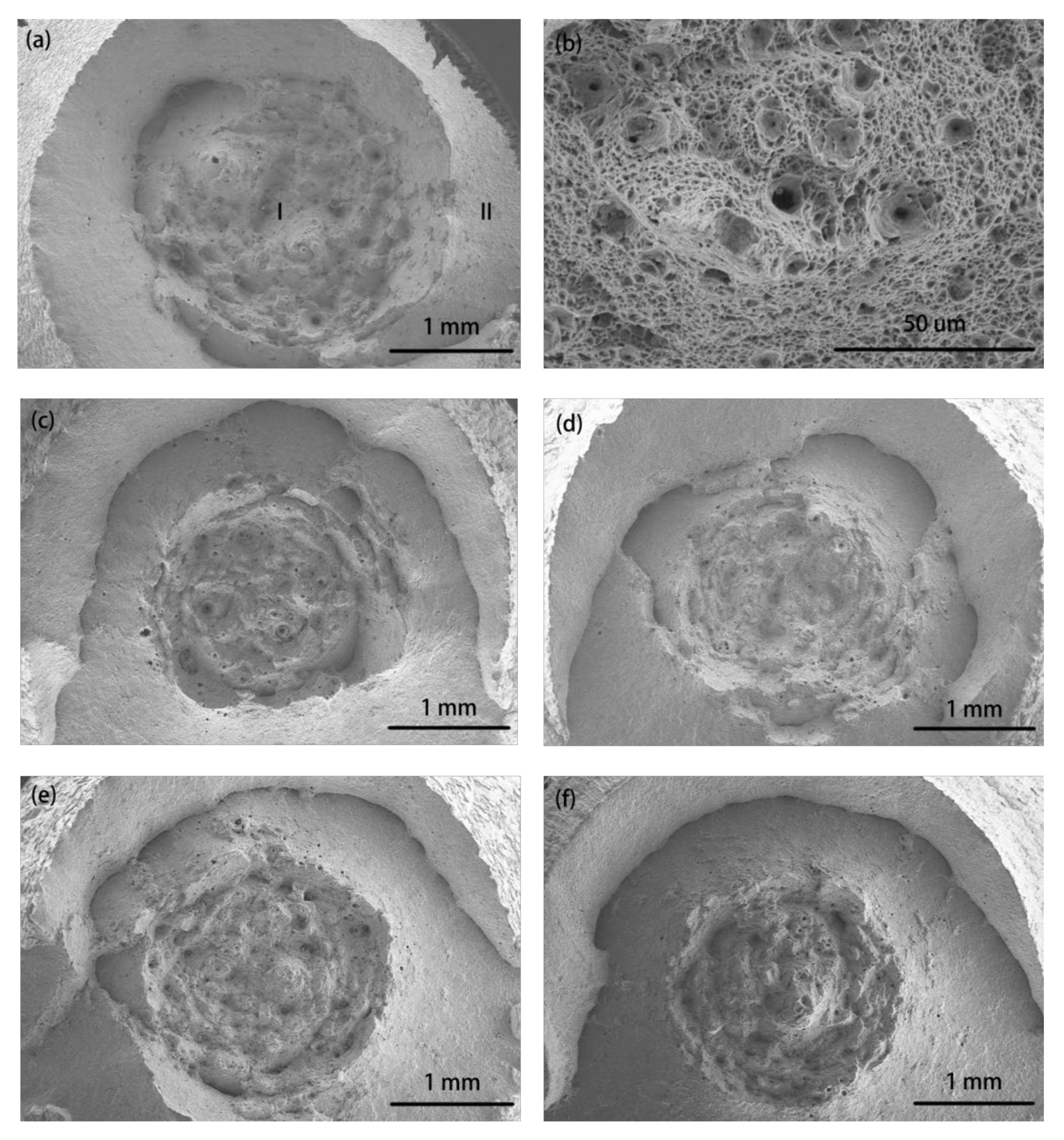
Figure 3 shows the variation of accumulated engineering strain with endurance life under static creep and cyclic creep tests. The evolutions of accumulated strain under all cyclic creep loadings exhibit three similar typical stages to static creep, which includes primary creep, secondary creep, and tertiary creep stages. The primary creep stage of 2.25Cr-1Mo steel is quite short. This feature was also observed under the ratcheting-fatigue tests of 2.25Cr-1Mo-V steel [28]. Subsequently, the strain accumulation rate quickly decreases and remains constant after entering the secondary creep stage. The secondary creep stage accounts for nearly 80% of the endurance life and is also referred to as the stable stage. It appears that the stable strain accumulation rate under cyclic creep is much lower than the one under static creep. It confirms that 2.25Cr-1Mo steel under cyclic creep shows retardation in the accumulation of strain compared with the static creep, similar to other Cr-Mo steels [10,29]. Moreover, the accumulation of the strain rate and endurance life are different with different unloading conditions. It indicates that the influence of anelastic recovery seems to change with different unloading rates and different valley stress durations. The details are discussed and can be found in Section 3.3.
Figure 3.
The accumulated strain–endurance life curves under all test conditions.
3.2. Fracture Mode
The elongation of all fractured specimens is presented in Figure 4. Cyclic creep loading leads to a slight drop in ductility as compared with static creep. However, the difference in ductility under cyclic creep seems to have little influence on endurance life. Research results showed that the fracture mode transformed from the brittle type to the ductile one and gradually approached static creep failure with the increase in duration under peak stress [11]. In this present study, a relatively long peak stress duration of 60 min has been imposed under all cyclic creep tests which means the fracture mode is most likely to be ductile, as for static creep.
Figure 4.
Fracture elongation of the specimen to the endurance life.
Typical fractographic morphologies of the fractured specimens under static creep and various cyclic creep tests are demonstrated in Figure 5. All the fractographies present a typical ductile failure feature with a similar cup-cone shape of necking. Two different areas including the (I) inner fibrous zone and (II) outer shearing lip can be found in Figure 5a. Creep dimples and cavities located at the center of the fibrous zone are shown in Figure 5b. Comparing with static creep, Figure 5c–f show that the fibrous zone area under cyclic creep suffers from shrinkage and this defect is more obvious in the case of a higher duration of valley stress. Besides, the distinct fatigue–creep cracks that were generated under cyclic loading in 9–12% Cr-Mo steels [30,31] are hardly detected in the examined 2.25Cr-1Mo steel. The test environment in air and the relatively low frequency adopted in this work are the possible reasons for this.
Figure 5.
SEM observations of fractured surfaces: (a) static creep and (b) enlarged inner fibrous zone; (c) cyclic creep at 12 and (d) 39 MPa/s unloading rate without valley stress duration; (e) cyclic creep with 10 and (f) 30 min duration under valley stress with an unloading rate of 12 MPa/s.
3.3. Anelastic Recovery Response
In order to obtain the value of the anelastic recovery strain and discuss the effects of the unloading rate and valley stress duration on the anelastic recovery response, the stress–strain curve is classified as follows.
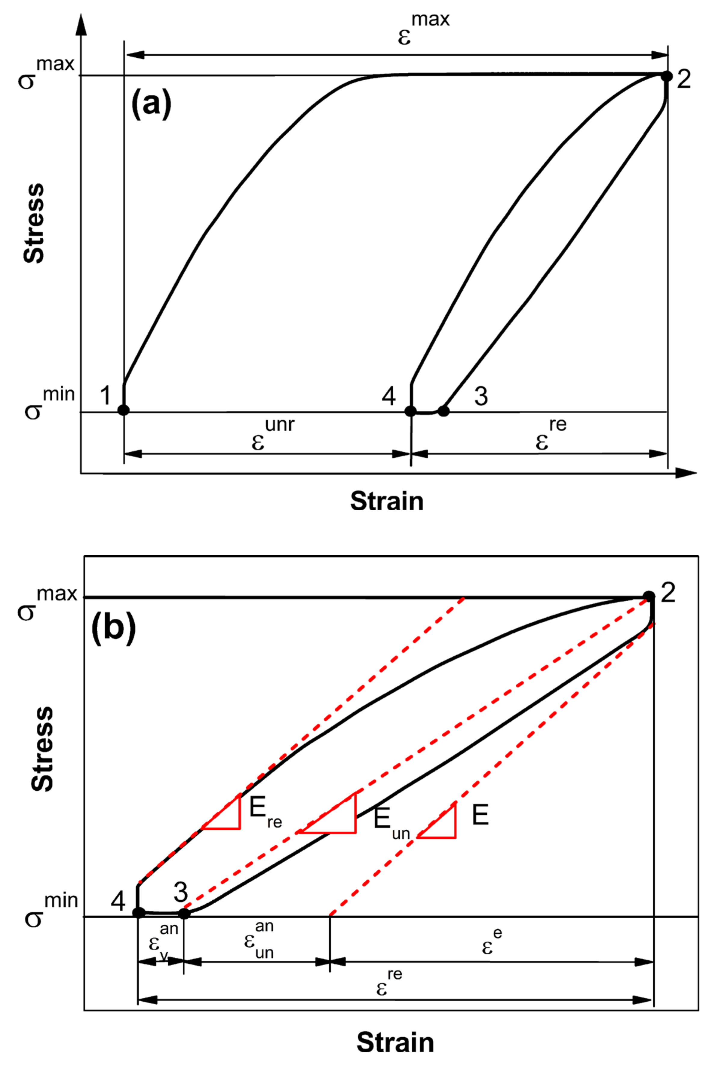
3.3.1. Strain Classification
The stress–strain curve under cyclic creep is shown schematically in Figure 6, where and are the peak and valley applied stresses, respectively. The loading elastic modulus E and the reloading elastic modulus correspond to the slope of the loading stress–strain curve in the elastic range. The unloading modulus , considering its nonlinearity and complexity [32,33], can be adequately defined by the straight line connecting the peak stress and the valley stress along the unloading stress–strain curve. This is according to the fitting method of the chord modulus [34]. The strain within the two adjacent cycles can be divided into three parts as illustrated in Figure 6a including (I) , the maximum strain of one cycle which contains elastic and plastic strains during loading and peak stress holding stages; (II) , the total recovery strain; and (III) , the unrecoverable strain compared to the last adjacent cycle. As shown in Figure 6b, the total recovery strain can be further divided into three parts consisting of elastic recovery strain and two parts of anelastic recovery strain, namely and . represents the recovery of the elastic part which is related to the loading elastic modulus. For the anelastic recovery strain of the unloading stage , the value depends on the difference of the unloading elastic modulus and the loading elastic modulus which can be separated during the unloading process. Considerably, the elastic recovery strain and anelastic strain occurred simultaneously rather than separately [35]. Moreover, for the anelastic recovery strain near valley stress , it represents the further reverse slip displacement of dislocations after the unloading stage. This part of the anelastic strain under the low-stress region is regarded as the major anelastic recovery in cases with a long duration under valley stress [20]. The two parts of anelastic recovery strain indicate the existence of a two-stage recovery phenomenon when the applied stress is removed which is closely related to the change of the elastic modulus [36] and the motion of dislocations [37].
Figure 6.
(a) Schematic diagram of the classification of strains within two adjacent cycles and (b) further classification of the total recovery strain.
All the strains can be obtained from experimental data, and the relationships are presented as the following:
where , , , and refer to the strains at different time points as shown in Figure 6.
According to the above systematic classification, it is clear that the elastic recovery strain reverses the elastic parts of the previous maximum strain completely and the two parts of the anelastic recovery strain play a vital role in recovering the plastic part of the maximum strain. The ultimate unrecovered strain is the true damage that dominates the failure of the cyclic creep. Besides, the anelastic recovery strain under varied unloading conditions can be obtained and analyzed quantitatively.
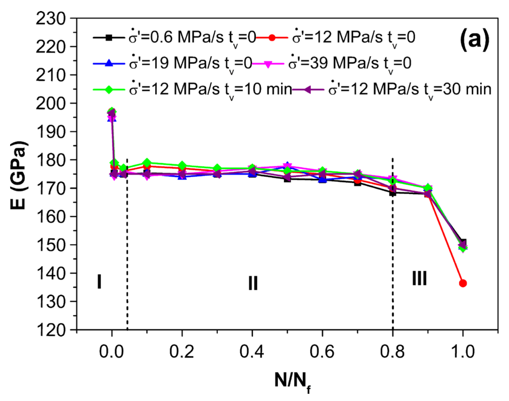
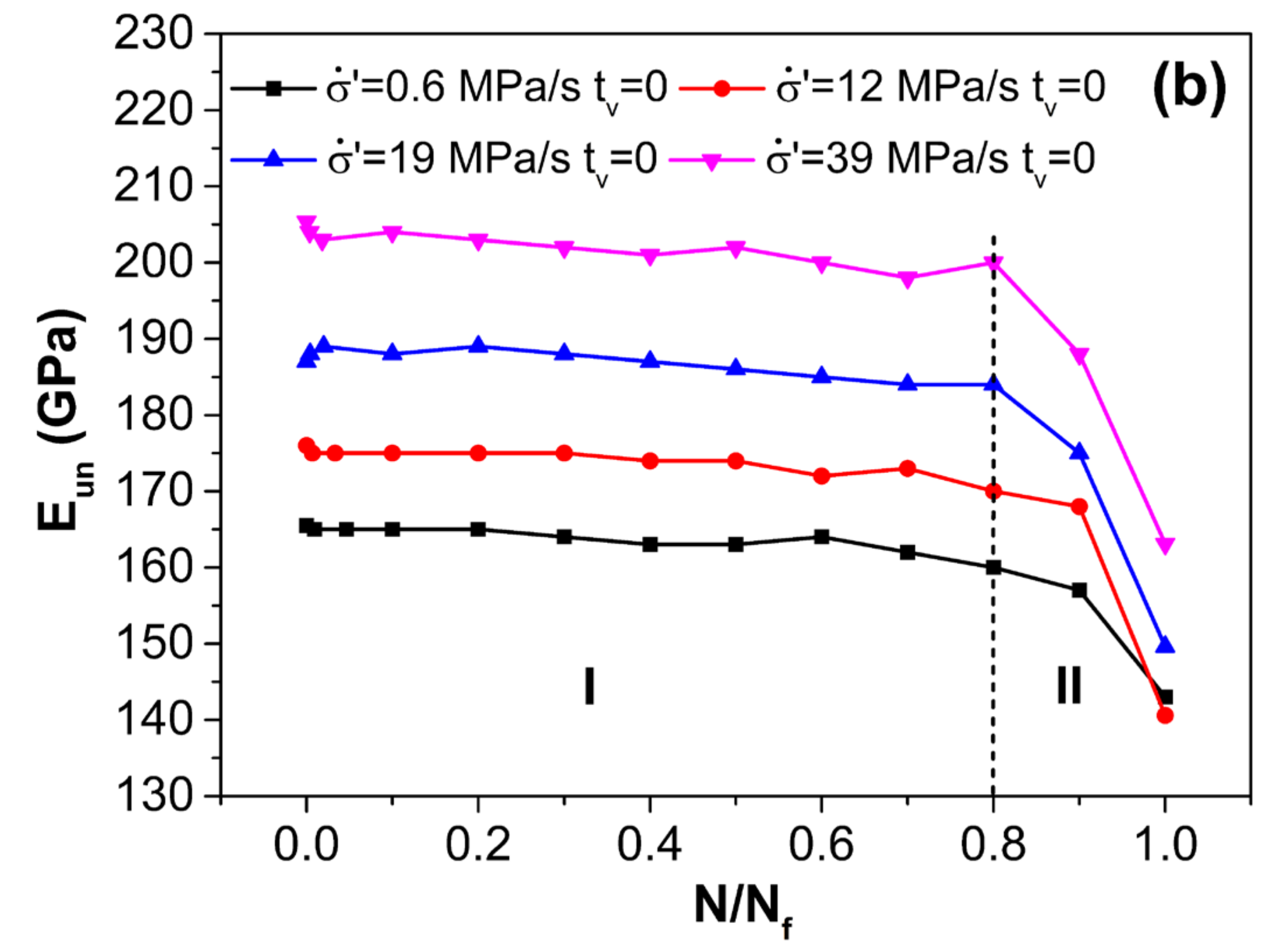
3.3.2. Effect of Unloading Rate
Previous works [38,39] have concluded that the ratcheting strain per cycle was influenced by loading and unloading rates which could be reflected by the loading and the unloading elastic modulus intuitively. In this work, as shown in Figure 7a, the value of the loading elastic modulus E is approximately consistent when the loading rate is fixed which is hardly affected by changed unloading conditions. The evolution during the entire life shows that E is large at the first cycle and then rapidly drops to a stable value, and further declines before fracture. In Figure 7b, the evolution of displays just two stages, where it is stable initially with a slight decrease and finally declines drastically before fracture. This indicates that the value of the unloading elastic modulus is quite sensitive to the unloading rate and it increases greatly with an increase in the unloading rate. Thus, the value of under different unloading rates can be obtained as presented in Figure 8a, where it decreases with the increase in unloading rate and maintains a constant value after the first cycle. When the stress is unloaded to the valley in the case without a duration of valley stress, the evolution of under different unloading rates is shown in Figure 8b. The value of also maintains constant during the stable stage. It is interesting to find that the value of increases significantly with the increase in unloading rate which is opposite to the trend of . Moreover, the correlation between anelastic recovery and dislocations motion could be reflected by a micromechanical modeling [40]. In this work, the range of applied stress amplitude is constant in all tests (= 455 MPa and R = 0.0375), thus a higher unloading rate leads to a shorter unloading time. Hence, the reverse slip displacement of dislocations appears less within a shorter time which causes the lower during the unloading stage. Meanwhile, more back stress remains after the stress is unloaded to the valley. Therefore, when the duration of valley stress is the same, the dislocations seem to be driven backward for a more prolonged displacement under more back stress, i.e., the higher .

Figure 7.
Elastic modulus of (a) loading and (b) unloading during the entire life under different unloading conditions.
Figure 8.
Evolutions of the anelastic recovery strain during the entire life for different unloading rates: (a) anelastic recovery strain of the unloading stage, , and (b) anelastic recovery strain near valley stress, .
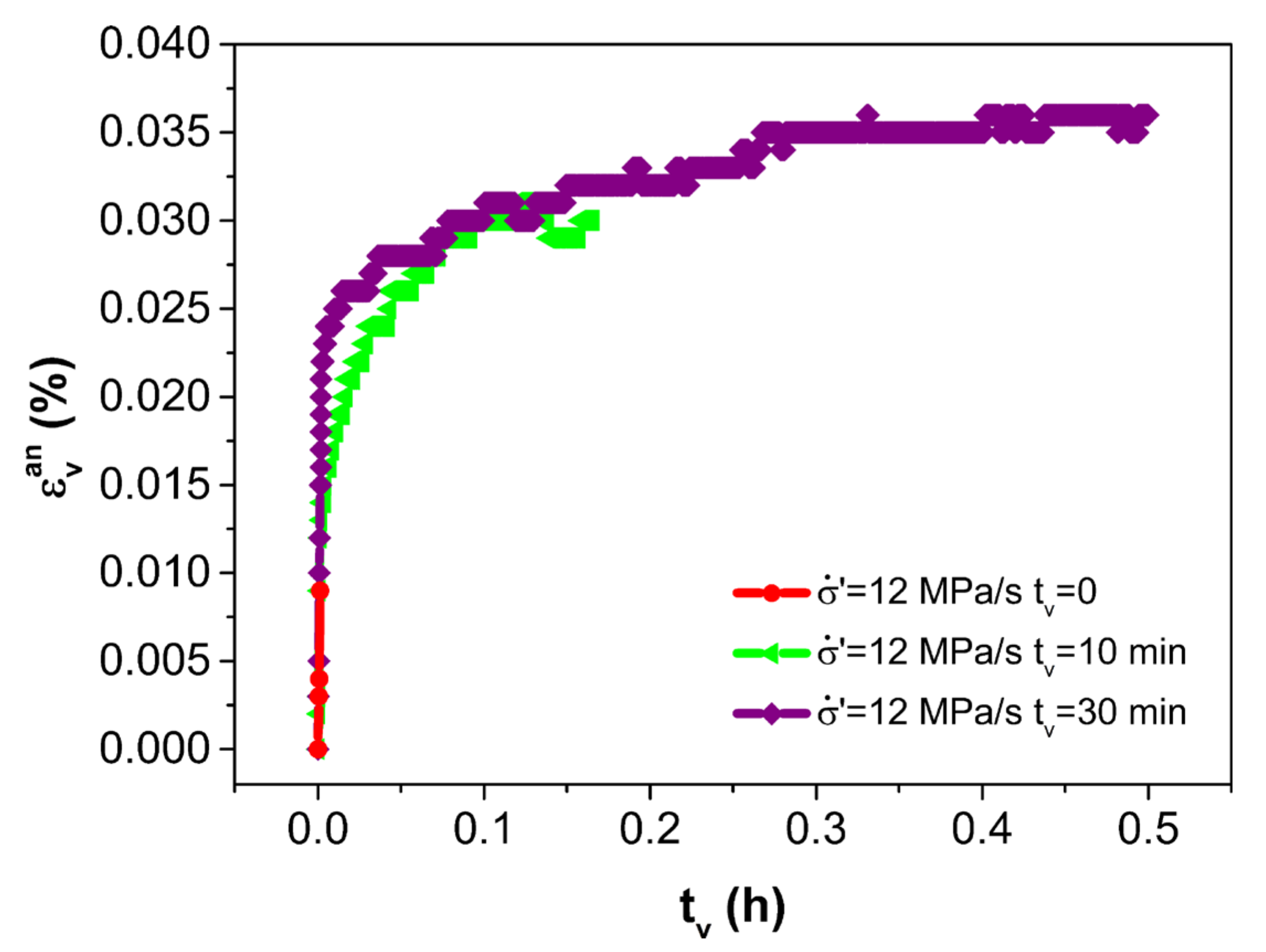
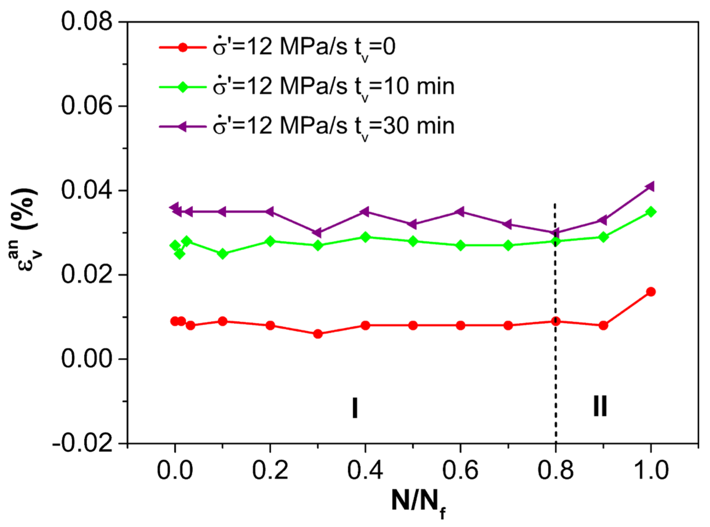
3.3.3. Effect of Duration under Valley Stress
When the loading and unloading rates are consistent, the value of is fixed by the same loading and unloading elastic modulus. Hence, the duration of the valley stress becomes the main factor to influence the value of . Figure 9 presents the typical evolution of during the second cycle for different valley stress durations. It appears that develops with extended durations of valley stress and the increment extent decreases when the duration of valley stress is more than 10 min. The saturation of anelastic strain with time was reported in other studies [20,41]. It confirms that the anelastic reverse slip displacement of 2.25Cr-1Mo steel is time-dependent, while the slip displacement is finite. Moreover, Figure 10 shows the evolution of during the entire life under different durations of valley stress, which presents two stages and all the values remain constant during most of the life.
Figure 9.
Evolutions of anelastic recovery strain near valley stress with time of the second cycle for different durations under valley stress.
Figure 10.
Evolutions of anelastic recovery strain near valley stress during the entire life for different durations under valley stress.
3.4. Modified Life Prediction Considering Anelastic Recovery
According to the above analysis, anelastic recovery behavior has a distinct effect on life prolongation and will change with various unloading parameters. Therefore, in terms of the life prediction of the cyclic creep test, the method should specifically consider the component of the anelastic recovery. According to other research, the life prediction methods based on stress control are fewer than strain control due to the unclosed hysteresis loops [42,43]. Most of methods neglected the effect of anelastic recovery such as the R5 method and led to over-conservative predicted results [20].
Based on the above study on each component of strain under cyclic creep, the unrecoverable strain based on the differences in the maximum strain and the recovery strains can be obtained with a stable value of 0.5 . It can be considered as the true damage parameter of . The parameters under different unloading conditions are summarized in Table 4.
Table 4.
Summary of the damage parameter of with cycles to failure.
Based on ductile exhaustion theory, the true damage per cycle can be expressed as
where is the fracture strain of the failed specimen, and and are the maximum strain and the total recovery strain, respectively, as mentioned above. It should be noted that can be assumed to follow a power law relationship with the damage parameter generally. Thus, a modified prediction equation can be obtained as
where and are fitting constants depending on the material type. As shown in Figure 11, the relationship between and under different unloading conditions can be well linearly fitted by Equation (3) in the double logarithmic coordinates, where = 14.431, and = −0.577. A comparison of the predicted and experimental results from the modified method in the present work is shown by the black dots in Figure 12. It can be observed that all the predicted results fall within a scatter band of ±1.5 with quite high accuracy.
Figure 11.
Liner fitting between unrecoverable strain of 0.5 and cycles to failure.
Figure 12.
Comparison of predicted and observed cycles to failure in cyclic creep.
It can be further speculated that if a creep–fatigue test under stress control meets the condition that the stable stage occupies most of the life, the unrecoverable strain of 0.5 can still estimate the life regardless of the changed test conditions. As such, the cyclic creep data of bainite 2.25Cr-1Mo-V steel at 455 °C can be used to further check the suitability of the proposed model. For the case of a short-term duration of hold stress and a negative stress ratio, the blue square points of Figure 12 present the comparison of the predicted and experimental results in the work of Zhao et al. [28]. It appears that all the predicted results fall within a scatter band of ±1.5. Therefore, the damage parameter can excellently reflect the failure process of cyclic creep under various stress-controlled test conditions.
4. Conclusions
Uniaxial stress-controlled static and cyclic creep tests of bainite 2.25Cr-1Mo steel were performed at 455°C. Effects of various unloading parameters including the unloading rate and duration under valley stress on the cyclic creep deformation behavior were discussed. Several conclusions were drawn:
- (1)
- Longer endurance life was obtained under cyclic creep compared with the static creep life, which was attributed to the effect of anelastic recovery. A consistent ductile fracture mode was observed under static and cyclic creep loadings, however, the ductility of the specimen that failed after cyclic creep was slightly lower than that after static creep.
- (2)
- The unloading elastic modulus varied with different unloading rates. The anelastic recovery strain during the unloading period showed dependence on both the unloading rate and valley stress duration. Based on the strain classification, the evolutions of the two parts of the anelastic recovery strain with the entire life under different unloading conditions can be divided into distinct stages.
- (3)
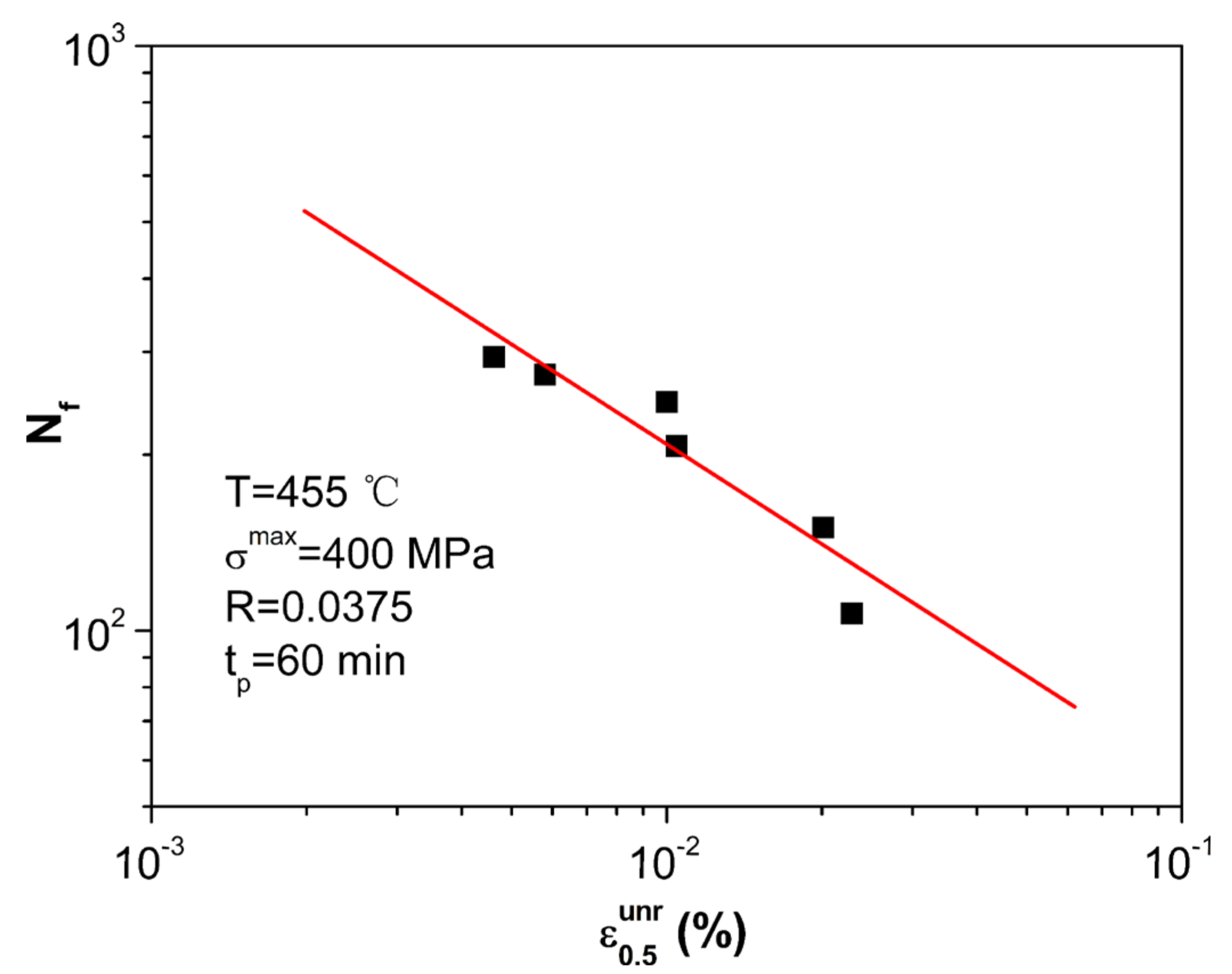
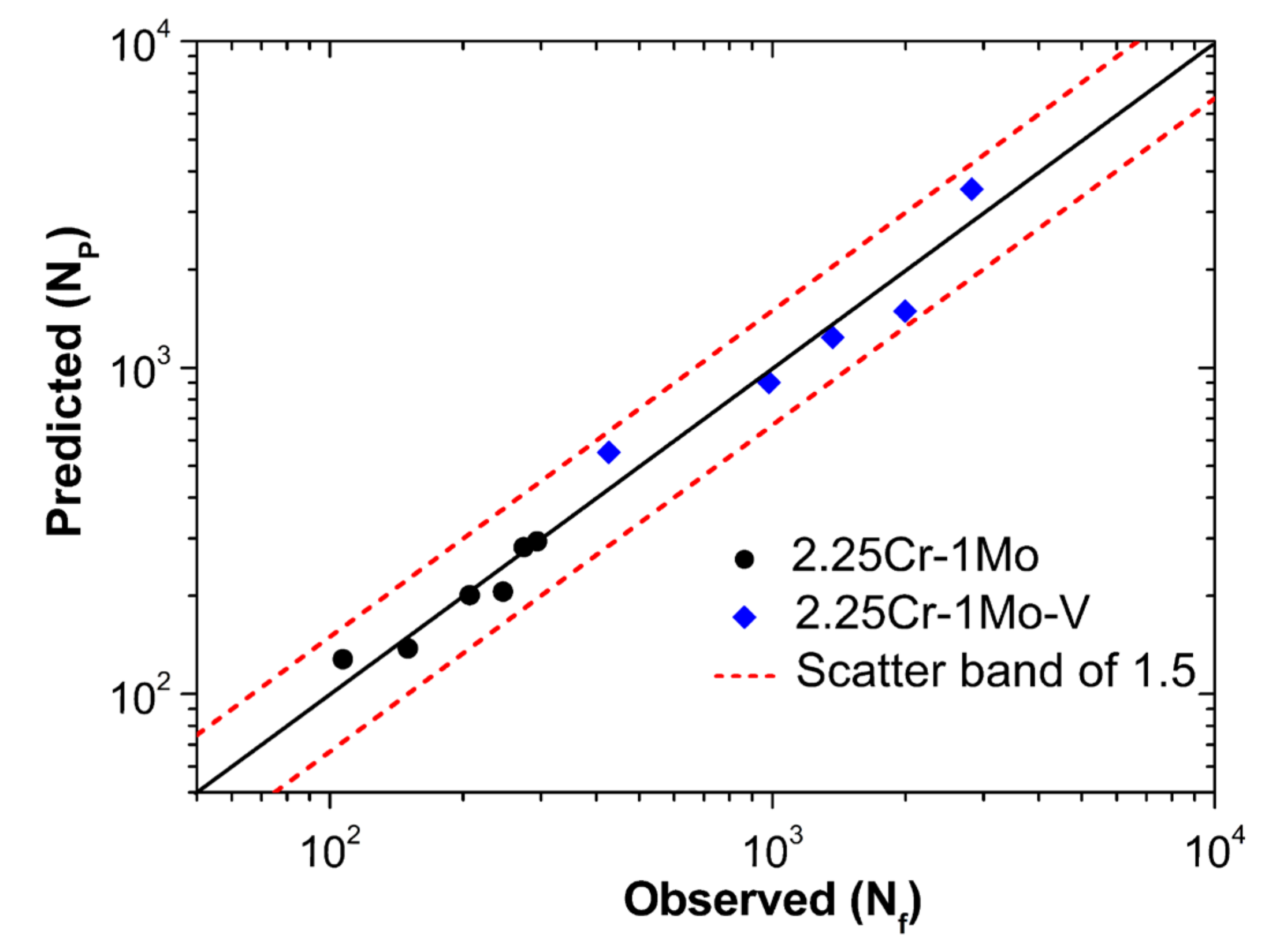
- The unrecoverable strain which referred to the true damage parameter was systematically considered by the classified strain components. Moreover, a modified life prediction method considering anelastic recovery was proposed, which presented extremely satisfactory estimated results for cyclic creep under various conditions.
Author Contributions
H.J. wrote the paper and completed cyclic creep tests. O.O. completed SEM observation. Z.Z. and B.L. reviewed and revised the paper. X.C. supervised the research and revised the paper. All authors have read and agreed to the published version of the manuscript.
Funding
The authors gratefully acknowledge the financial support from the National Key Research and Development Program of China (No. 2018YFC0808600).
Conflicts of Interest
The authors declare no conflict of interest.
References
- Okrajni, J.; Cie, M.; Swad, L. High-temperature low-cycle fatigue and creep behaviour of nickel-based superalloys with heat-resistant coatings. Fatigue Fract. Eng. Mater. Struct. 1998, 21, 947–954. [Google Scholar] [CrossRef]
- Liao, C.-C.; Wang, C.-C.; Chen, T.-C.; Shiue, R.-K.; Tsay, L.-W. Effects of Thermal Simulation on the Creep Fracture of the Mod. 9Cr-1Mo Weld Metal. Metals 2020, 10, 1181. [Google Scholar] [CrossRef]
- Kuběna, I.; Polák, J.; Płociński, T.P.; Hébert, C.; Škorík, V.; Kruml, T. Microstructural stability of ODS steels in cyclic loading. Fatigue Fract. Eng. Mater. Struct. 2015, 38, 936–947. [Google Scholar] [CrossRef]
- Natesan, E.; Ahlström, J.; Manchili, S.K.; Eriksson, S.; Persson, C. Effect of Strain Rate on the Deformation Behaviour of A356-T7 Cast Aluminium Alloys at Elevated Temperatures. Metals 2020, 10, 1239. [Google Scholar] [CrossRef]
- Zhan, N.; Hu, Z.; Zhang, X. Experimental Investigation of Fatigue Crack Growth Behavior in Banded Structure of Pipeline Steel. Metals 2020, 10, 1193. [Google Scholar] [CrossRef]
- Barua, B.; Mohanty, S.; Listwan, J.T.; Majumdar, S.; Natesan, K.; Majumdar, S. Methodology for Stress-Controlled Fatigue Test Under In-Air and Pressurized Water Reactor Coolant Water Condition and to Evaluate the Effect of Pressurized Water Reactor Water and Loading Rate on Ratcheting. J. Press. Vessel Technol. 2018, 140, 031403. [Google Scholar] [CrossRef]
- Oldroyd, P.W.J.; Radon, J.C. Reversal of cyclic creep in mild steel and copper. Fatigue Fract. Eng. Mater. Struct. 1979, 1, 297–306. [Google Scholar] [CrossRef]
- Ahmadzadeh, G.R.; Varvani-Farahani, A. Concurrent ratcheting-fatigue damage analysis of uniaxially loaded A-516 Gr.70 and 42CrMo Steels. Fatigue Fract. Eng. Mater. Struct. 2012, 35, 962–970. [Google Scholar] [CrossRef]
- Tian, J.; Li, J.; Xie, H.; Yang, Y.; Kan, Q. Finite Element Implementation of a Temperature-Dependent Cyclic Plastic Model for SA508-3 Steel. Metals 2018, 8, 955. [Google Scholar] [CrossRef]
- Zhao, P.; Xuan, F.-Z. Ratchetting behavior of advanced 9–12% chromium ferrite steel under creep–fatigue loadings: Fracture modes and dislocation patterns. Mater. Sci. Eng. A 2012, 539, 301–307. [Google Scholar] [CrossRef]
- Zhao, P.; Xuan, F.-Z. Ratchetting behavior of advanced 9–12% chromium ferrite steel under creep-fatigue loadings. Mech. Mater. 2011, 43, 299–312. [Google Scholar] [CrossRef]
- Hu, D.; Ma, Q.; Shang, L.; Gao, Y.; Wang, R. Creep-fatigue behavior of turbine disc of superalloy GH720Li at 650 °C and probabilistic creep-fatigue modeling. Mater. Sci. Eng. A 2016, 670, 17–25. [Google Scholar] [CrossRef]
- Matejczyk, D.E.; Zhuang, Y.; Tien, J.K. Anelastic relaxation controlled cyclic creep and cyclic stress rupture behavior of an oxide dispersion strengthened alloy. Met. Mater. Trans. A 1983, 14, 241–247. [Google Scholar] [CrossRef]
- Hu, X.; Zhang, Q.; Jiang, Y.; Rao, G.; Miao, G.; He, W.; Nie, X. The effect of cyclic loading on the creep fatigue life and creep strength of a DS superalloy: Damage mechanism and life modeling. Int. J. Fatigue 2020, 134, 105452. [Google Scholar] [CrossRef]
- Hong, K.T.; Lee, J.K.; Nam, S.W. Threshold stress for cyclic creep acceleration in copper. J. Mater. Sci. 1988, 23, 1569–1572. [Google Scholar] [CrossRef]
- Yasnii, P.V.; Halushchak, M.P.; Fedak, S.I.; Pidkol’Zin, V.Y. Cyclic creep of AMg6 alloy. Mater. Sci. 2000, 36, 48–53. [Google Scholar] [CrossRef]
- Wang, Z.-G.; Rahka, K.; Laird, C. Cyclic creep acceleration and retardation in Cr-Mo-V rotor steel at ambient and elevated temperature respectively. Fatigue Fract. Eng. Mater. Struct. 1986, 9, 219–230. [Google Scholar] [CrossRef]
- Bönisch, M.; Calin, M.; Van Humbeeck, J.V.; Skrotzki, W.; Eckert, J. Factors influencing the elastic moduli, reversible strains and hysteresis loops in martensitic Ti–Nb alloys. Mater. Sci. Eng. C 2015, 48, 511–520. [Google Scholar] [CrossRef]
- Blum, W.; Dvořák, J.; Král, P.; Eisenlohr, P.; Sklenička, V. Strain Rate Contribution due to Dynamic Recovery of Ultrafine-Grained Cu–Zr as Evidenced by Load Reductions during Quasi-Stationary Deformation at 0.5 Tm. Metals 2019, 9, 1150. [Google Scholar] [CrossRef]
- Zhang, S.-L.; Xuan, F.Z.; Guo, S.-J.; Zhao, P. The role of anelastic recovery in the creep-fatigue interaction of 9–12% Cr steel at high temperature. Int. J. Mech. Sci. 2017, 122, 95–103. [Google Scholar] [CrossRef]
- Hosseini, E.; Kalyanasundaram, V.; Li, X.; Holdsworth, S.R. Effect of prior deformation on the subsequent creep and anelastic recovery behaviour of an advanced martensitic steel. Mater. Sci. Eng. A 2018, 717, 68–77. [Google Scholar] [CrossRef]
- Na, H.-S.; Lee, S.-H.; Kang, C.-Y. Effect of Micro-Segregation on Impact Toughness of 2.25Cr-1Mo Steel after Post Weld Heat Treatment. Metals 2018, 8, 373. [Google Scholar] [CrossRef]
- Klueh, R.L. Heat treatment effects on creep and rupture behavior of annealed 2.25 Cr-1 Mo steel. Met. Mater. Trans. A 1978, 9, 1591–1598. [Google Scholar] [CrossRef]
- Jaske, C.E. Fatigue curve needs for higher strength 2-1/4Cr-1Mo steel for petroleum process vessels. J. Press. Vessel Technol. 1990, 112, 323–332. [Google Scholar] [CrossRef]
- Challenger, K.D.; Miller, A.K.; Brinkman, C.R. An explanation for the effects of hold periods on the elevated temperature fatigue behavior of 2 1/4 Cr-1 Mo Steel. J. Eng. Mater. Technol. 1981, 103, 7–14. [Google Scholar] [CrossRef]
- Callaghan, M.D.; Humphries, S.R.; Law, M.; Ho, M.; Bendeich, P.; Li, H.; Yeung, W.Y. Energy-based approach for the evaluation of low cycle fatigue behaviour of 2.25Cr–1Mo steel at elevated temperature. Mater. Sci. Eng. A 2010, 527, 5619–5623. [Google Scholar] [CrossRef]
- Zhang, J.; Yu, D.; Zhao, Z.; Zhang, Z.; Chen, G.; Chen, X. Low cycle fatigue of 2.25Cr1Mo steel with tensile and compressed hold loading at elevated temperature. Mater. Sci. Eng. A 2016, 667, 251–260. [Google Scholar] [CrossRef]
- Zhao, Z.; Yu, D.; Chen, G.; Chen, X. Ratcheting-fatigue behaviour of bainite 2.25Cr1MoV steel with tensile and compressed hold loading at 455°C. Fatigue Fract. Eng. Mater. Struct. 2019, 42, 1937–1949. [Google Scholar] [CrossRef]
- Kim, W.-G.; Park, J.-Y.; Ekaputra, I.M.W.; Kim, S.-J.; Jang, J. Cyclic creep behaviour under tension–tension loading cycles with hold time of modified 9Cr–1Mo steel. Mater. High Temp. 2014, 31, 249–257. [Google Scholar] [CrossRef]
- Fischer, T.; Kuhn, B. Influence of steam atmosphere on the crack propagation behavior of a 9–12% Cr ferritic/martensitic steel at temperatures from 300 °C to 600 °C depending on frequency and hold time. Int. J. Fatigue 2019, 119, 62–77. [Google Scholar] [CrossRef]
- Fischer, T.; Kuhn, B. Impact of frequency, hold time and atmosphere on creep-fatigue of a 9–12% Cr steel from 300 °C−600 °C. Int. J. Fatigue 2019, 124, 288–302. [Google Scholar] [CrossRef]
- Chen, M.-S.; Lin, Y.C.; Li, K.-K.; Chen, J. The nonlinear unloading behavior of a typical Ni-based superalloy during hot deformation: A new elasto-viscoplastic constitutive model. Appl. Phys. A 2016, 122, 869. [Google Scholar] [CrossRef]
- Chen, M.-S.; Lin, Y.-C.; Li, K.-K.; Chen, J. The nonlinear unloading behavior of a typical Ni-based superalloy during hot deformation: A unified elasto-viscoplastic constitutive model. Appl. Phys. A 2016, 122, 854. [Google Scholar] [CrossRef]
- Kim, H.; Kim, C.; Barlat, F.; Pavlina, E.; Lee, M.-G. Nonlinear elastic behaviors of low and high strength steels in unloading and reloading. Mater. Sci. Eng. A 2013, 562, 161–171. [Google Scholar] [CrossRef]
- Zheng, X.-T.; Xuan, F.-Z.; Zhao, P. Ratcheting-creep interaction of advanced 9–12% chromium ferrite steel with anelastic effect. Int. J. Fatigue 2011, 33, 1286–1291. [Google Scholar] [CrossRef]
- Yang, M.; Akiyama, Y.; Sasaki, T. Evaluation of change in material properties due to plastic deformation. J. Mater. Process. Technol. 2004, 151, 232–236. [Google Scholar] [CrossRef]
- Stefani, J.A.; Nardone, V.C.; Tien, J.K. On the refinement of the anelastic relaxation controlled cyclic creep model. Scr. Met. 1986, 20, 685–688. [Google Scholar] [CrossRef]
- Zheng, X.; Wu, K.; Wang, W.; Yu, J.; Xu, J.; Ma, L. Low cycle fatigue and ratcheting behavior of 35CrMo structural steel at elevated temperature. Nucl. Eng. Des. 2017, 314, 285–292. [Google Scholar] [CrossRef]
- Zheng, X.; Wang, J.; Gao, J.; Ma, L.; Yu, J.; Xu, J. Rate-dependent low cycle fatigue and ratcheting of 25Cr2MoVA steel under cyclic pulsating tension. Mater. High Temp. 2017, 35, 482–489. [Google Scholar] [CrossRef]
- Mareau, C.; Favier, V.; Weber, B.; Galtier, A.; Berveiller, M. Micromechanical modeling of the interactions between the microstructure and the dissipative deformation mechanisms in steels under cyclic loading. Int. J. Plast. 2012, 32–33, 106–120. [Google Scholar] [CrossRef]
- Morris, D.G. Anelasticity and creep transients in an austenitic steel. J. Mater. Sci. 1978, 13, 1849–1854. [Google Scholar] [CrossRef]
- Fan, Z.; Chen, X.; Chen, L.; Jiang, J. Fatigue–creep behavior of 1.25Cr0.5Mo steel at high temperature and its life prediction. Int. J. Fatigue 2007, 29, 1174–1183. [Google Scholar] [CrossRef]
- Zhu, Y.; Kang, G.; Yu, C. A finite cyclic elasto-plastic constitutive model to improve the description of cyclic stress-strain hysteresis loops. Int. J. Plast. 2017, 95, 191–215. [Google Scholar] [CrossRef]
Publisher’s Note: MDPI stays neutral with regard to jurisdictional claims in published maps and institutional affiliations. |
© 2020 by the authors. Licensee MDPI, Basel, Switzerland. This article is an open access article distributed under the terms and conditions of the Creative Commons Attribution (CC BY) license (http://creativecommons.org/licenses/by/4.0/).