Abstract
The development of customised aluminium alloys for welding and additive manufacturing (AM) is proposed to solve several quality issues and to enhance the mechanical integrity of components. The introduction of ceramic grain refining agents shows great potential as alloy addition as to limit cracking susceptibility and increase the strength. Thus, a versatile solid-state manufacturing route for nanoparticle reinforced aluminium wires has been developed based on the metal screw extrusion principle. In fact, the Al-Si alloy AA4043 mixed with 1 wt.% TiC nanoparticles has been manufactured as a wire. The accumulated strain on the material during metal screw extrusion has been estimated, classifying the process as a severe plastic deformation (SPD) method. A chemical reaction between silicon and TiC particles after metal screw extrusion was found, possibly limiting the grain refining effect. Electric arc bead-on-plate deposition was performed with metal screw extruded and commercial material. The addition of TiC induced a grain morphology transition from columnar to equiaxed after electric arc deposition, and increased the hardness. A high amount of porosity was found in the AA4043-TiC material, probably arising from hydrogen contamination on TiC surfaces prior to metal screw extrusion. The results are encouraging as a new direction for aluminium alloy development for additive manufacturing.
1. Introduction
1.1. Wire and Arc Additive Manufacturing of Aluminium Alloys
Manufacturing of three-dimensional shapes by layer wise arc welding is referred to as wire and arc additive manufacturing (WAAM). The process experiences great attention from scientific as well as engineering communities due to high deposition rates, high material utilisation and low investment costs compared to other AM processes. WAAM of aluminium alloys is expected to be a vital contributor in automotive, aviation and aerospace industries due to their high specific strength and excellent corrosion properties [1]. However, WAAM of aluminium alloys needs to overcome several obstacles before the process can obtain commercial applicability. Wu et al. reported quality issues regarding anisotropic mechanical properties, relatively coarse grain size and hot crack susceptibility of deposited materials [2]. Only a handful of alloys from the AA2xxx (Al-Cu), 4xxx (Al-Si) and AA5xxx (Al-Mg) wrought alloy systems have been proven acceptable for WAAM [3,4,5].
The introduction of grain refining agents in the wire feedstock is a proposed solution to eliminate the mentioned quality issues and to expand the aluminium alloy selection for WAAM. The principle was introduced in powder-based AM by Martin et al., where aluminium powders were covered with hydrogen stabilised zirconium nanoparticles [6]. The nanoparticles served as heterogeneous nucleation sites for aluminium upon solidification and changed the dendritic morphology from columnar to equiaxed. The grain morphology transition eliminated crack susceptibility due to enabled backfilling and distribution of remaining melt under solidification. Due to an extensive grain refinement, the shrinkage stresses associated with several aluminium alloy systems were distributed over a larger grain boundary area. Consequently, hot tearing susceptible alloys like AA6061 and AA7075 were proven acceptable for powder-based AM. Sales and Ricketts modified an Al-Mg WAAM feedstock with scandium in order to promote grain refinement and precipitation hardening [7]. Scandium modified materials exhibited a significant finer grain size and increased tensile strength.
Titanium carbide (TiC) nanoparticles provide grain refinement and particle strengthening in aluminium alloys when used in WAAM and arc welding. Sokoluk et al. showed that the hot tearing susceptible alloy AA7075 could be used as welding feedstock by adding nanosized TiC particles [8]. The modified AA7075-TiC weld possessed a tensile strength close to 550 MPa after a T6 thermal treatment. This modified alloy was prepared by liquid state processing, i.e., casting, before further processing to a wire.
Solid state processing of wire feedstock is less energy consuming, has a lower carbon footprint, and restricts the risk of nanoparticle agglomeration and sedimentation compared to liquid state processes. Solid state processing of wire feedstock is mainly associated with accumulated roll bonding (ARB). Fattahi et al. produced well dispersed AA4043-TiC wires for gas tungsten arc welding (GTAW) by an eight cycle ARB [9,10]. The TiC-reinforced weld nuggets exhibited superior strength compared to an unreinforced counterpart. The authors attributed this effect to grain refinement, restricted dislocation slip by Orowan strengthening and an increased dislocation density originating from particle-matrix thermal mismatch upon solidification. Hence, the introduction of ceramic particles in aluminium WAAM feedstock shows great potential as to enhance the mechanical integrity and for broadening the range of useable aluminium alloys.
Current manufacturing techniques of nanoparticle reinforced feedstock for WAAM and welding are through semi-continuous methods like casting and rolling. Wires prepared by rolling (ARB) are cumbersome to manufacture. Casting routes involve many processing steps, have a high energy consumption and restrict the nanoparticle selection due to challenges associated with agglomeration. Therefore, a direct, continuous, low-energy manufacturing method is sought for preparing aluminium WAAM feedstock containing grain refinement agents. Hence, this study will examine the applicability of the novel metal screw extrusion process. As-extruded as well as bead-on-plate depositions of produced materials with and without additions of TiC will be characterised in terms of grain structure, phase composition, nanoparticle dispersion and mechanical properties.
1.2. Metal Screw Extrusion
Werenskiold et al. patented the metal screw extrusion method in collaboration with Hydro Aluminium and the Norwegian University of Science and Technology (NTNU) [11]. The manufacturing principle is based on the known single screw extrusion technology commonly utilised in polymer and food industries. A prototype extruder developed at NTNU comprises an electrical engine driving an Archimedes screw through a gear box. The screw is surrounded by a stationary liner and the screw channel is the open space between the stem of the screw and the liner, see Figure 1. A conical-shaped container segment extends the liner in front of the screw tip to form an extrusion chamber. The profile is extruded through a die mounted at the extrusion chamber terminal position, i.e., right-hand side in Figure 1.
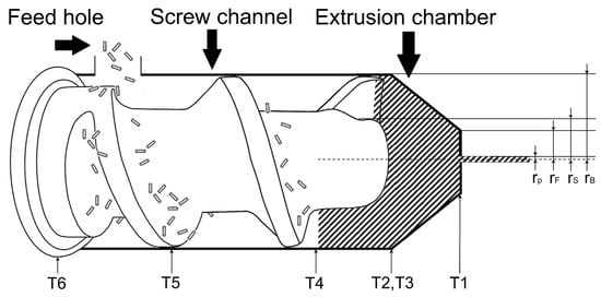
Figure 1.
Principal sketch of the metal screw extrusion process showing granule feeding on the left-hand side and material consolidation into a solid plug in the hatched area. A dense profile is extruded on the right-hand side. The process is monitored by thermocouples T1–T6.
Continuous extrusion is maintained by feeding material at the rear end of the screw. The fed material is first transported forward by the push of the screw wing. As a solid plug is formed along the screw channel, friction forces act between the screw flight, liner, chamber walls and the material. These friction forces form the basis for forward motion of fed material in the metal screw extruder. At the screw tip, i.e., towards the extrusion chamber, the material is smeared onto the solid plug as illustrated by the hatched area in Figure 1. When the pressure in the extrusion chamber surpasses the material flow stress, extrusion initiates through the die and is maintained by steady state feeding. Unlike polymer screw extrusion, the fed material is always in solid state during metal screw extrusion.
Due to the high viscosity of metals, strains associated with metal screw extrusion can be severe. An analytic model proposed by Skorpen et al. divides the metal screw extrusion process into four segments, where each segment contributes to the total strain [12]. The four segments include,
- Extrusion through the die
- Mass transport through the solid plug in the extrusion chamber
- Shearing of material from the screw tip into the extrusion chamber
- Movement and consolidation of feedstock in the screw channel
Segment 1 is according to [12] modelled as conventional ram extrusion, where the solid material plug in the extrusion chamber acts as the ram. This solid material plug is continuously pushed forward by the oncoming material at the screw tip. The associated strain is proportional to the reduction ratio between a circular profile with radius and radius of the screw plug tip (the most forward position of the above-mentioned conical extrusion chamber) , given by Equation (1):
Strain in the extrusion chamber (Segment 2) is estimated by a high pressure torsion (HPT) analogy. The shear stress , i.e., the torsional contribution, is described by Equation (2). The strain in Segment 2, , is then calculated by Equation (3), including the reduction ratio of this segment. Here, represents the radius of each HPT-segment i, the rotation difference of each segment i, being the height of each segment, the length of the extrusion chamber and radius of the extrusion chamber closest to the screw tip. Segment 3 involves smearing of new material onto the solid mass in the extrusion chamber, i.e., the screw plug. The segment is as a first approximation regarded as a reversed milling process with corresponding shear strain given by Equation (4). is the pitch angle of the screw flight and the shear angle in a chip machining process. The resulting strain component is given in Equation (5).
Skorpen et al. [12] further assumed that compaction and transport in the screw channel (Segment 4) create a shear strain component arising from friction between the stationary liner wall and the rotating material inside the screw channel, i.e., between the screw flights and the container wall. The material flow is believed to be quite complex and is, as a first approximation, simplified to consist of a rotational movement component only. An HPT approach is used to determine the shear strain in this region, , given by Equation (6). is radius of the screw stem, L the length along the screw channel containing compacted material, A cross section area of the screw channel, the material density, rotational velocity of the screw and the feed rate. The resulting equivalent strain follows from Equation (7).
It is emphasised that metal screw extrusion has a very complex material flow. This flow has partly been revealed by Widerøe and Welo using contrast materials, however not all segments were for practical reasons possible for investigation [13]. The analytic model of [12] should for this reason be regarded as a first approximation. It is finally assumed that each strain contribution , , and , is additive giving the total strain , shown in Equation (8).
2. Materials and Methods
A flowchart for the performed activities is provided in Figure 2. The start material was the wrought alloy AA4043, commonly used as filler material for welding. The material was produced as high quality welding wire with diameter Ø1.2 . The wire was used to prepare the feedstock for metal screw extrusion processing. This wire will in later bead-on-plate trials be used as a reference to the wire described herein. The chemical composition of the AA4043 material is given in Table 1, as provided by the supplier [14].
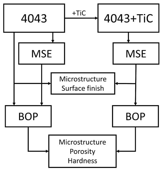
Figure 2.
Flowchart for development of feedstock wires for wire and arc additive manufacturing (WAAM) by metal screw extrusion (MSE). Commercial AA4043 wire was used as starting material and benchmark. Bead-on-plate (BOP) deposition simulates a WAAM base layer.

Table 1.
Typical element composition of AA4043 Ø1.2 wire in wt.% [14].
AA4043 wire was cut into 25 ± 10 granules by a rotating knife, see Figure 3. The knife blades were lubricated in oil which contaminated the granules. Any residues, if left on the granules, would be detrimental for the quality of the produced wire. Thus, the granules were cleaned for 60 s in acetone and rinsed in water, immediately followed by thermal drying at 125 for 24 h. Following this, the material was heated to 350 for 60 min to ensure removal of any organic residuals.
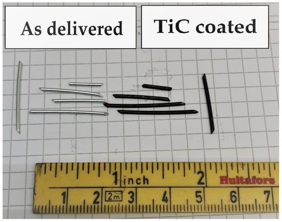
Figure 3.
AA4043 granules before (left) and after dry coating (right) with titanium carbide (TiC).
Subsequently, the granules were mixed with 1 wt.% TiC powder in a cylindrical plastic container, which was then carefully sealed. The titanium carbide nanoparticles (TiC, 99+ wt.%, 40–60 , cubic) were purchased from US Research Nanomaterials Inc., Houston, TX, USA. The aluminium and TiC mixture was roll mixed (IKA Roller 10 Digital, IKA-Werke GmbH & Co. KG, Staufen, Germany) at 70 rpm (7.33 rad/s) for five days in air. A black, dry coating of TiC was observed on the granules, as seen in Figure 3.
The screw operated with a rotational velocity equal to 3 rpm (0.314 rad/s). The screw channel was cooled by compressed air passing through channels in the screw liner, in order to avoid overheating of the metal screw extruder. The AA4043-TiC feedstock was metal screw extruded to a wire with similar dimensions as the parent AA4043 wire, i.e., Ø1.1–1.2 . The temperature in the metal screw extruder was monitored by six thermocouples (T1–T6) with positions indicated in Figure 1. The extrusion temperature measured by thermocouple T1 was in the range of 520–540 and the produced wire was cooled in air. The maximum temperature in the metal screw extruder was kept below the eutectic temperature for Al-Si alloys (i.e., 577 ), in order to avoid a partial melting of the AA4043 alloy.
The commercial AA4043 wire, as well as metal screw extruded AA4043 and AA4043-TiC wires, were deposited by gas metal arc welding (GMAW, Fronius International GmbH, Wels, Austria) on a 4 thick AA6082 plate. One bead for each material was laid, corresponding to the base layer of a WAAM deposit. GMAW was performed with current , voltage and travel speed . The corresponding gross heat input () was 211 .
Investigated materials were prepared for microstructural examination through standard metallographic procedures. This included mechanical grinding with water-lubricated silicon carbide discs and polishing on cloths with water-based diamond suspensions. Colloidal silica dispersion with diameter 0.04 μm was used at the final stage to obtain a mirror finish.
The dispersion of nanoparticles in the metal screw extruded AA4043-TiC material was studied in scanning electron microscopy (SEM, Zeiss Ultra 55, Carl Zeiss AG, Jena, Germany), applying an energy dispersive X-ray spectroscopy (EDS) mapping system (Bruker QUANTAX, Bruker Corporation, Billerica, MA, USA). Overall, 300 titanium-containing particles in the screw plug were qualitatively classified as TiC or Ti-Si-Al intermetallic () by EDS and the number fraction was calculated. The SEM was used in secondary electron and backscatter electron imaging mode with working distance 10 , acceleration voltage 10 and 120 aperture. The AA4043-TiC wire was characterised by X-ray diffraction (XRD, D8 Advance DaVinci diffractometer, Bruker Corporation, Billerica, MA, USA). The XRD apparatus employed Mo radiation with 2 angles between 7–65 with step size of 1. X-ray absorption in the material was estimated using the Cromer and Liberman algorithm and was found to be within an acceptable range [15]. Obtained XRD patterns were compared with ICDD PDF® database spectra for the given radiation source to identify the present phases. Hardness was determined by Vickers micro-hardness testing using 100 g force (HV, Matsuzawa MXT0, Matsuzawa Co., Ltd., Akita, Japan) with six indentations taken in accordance to ISO 6507-1:2018 [16]. The wire surface quality was characterised by SEM secondary electron imaging and optical profilometer measurements (Alicona InfiniteFocus, Alicona GmbH, Graz, Austria).
3. Results and Discussion
3.1. Accumulated Strain by Metal Screw Extrusion
The total strain subjected to the metal screw extruded Ø1.2 wires has been estimated by Equation (8). Figure 4 presents the total strain which ranges from 15–21. A range of feed rates was included in the estimation to account for the effect of uneven convey of material into the metal screw extruder. The material in the extrusion chamber, termed screw plug, does not rotate at the same velocity as the screw. Hence, some velocity is lost due to the smearing of new material and backflow at the screw flight tip. The effect of velocity difference has previously been termed the screw efficiency factor, k. Initial considerations from Skorpen et al. suggest [12]. However, these estimations have been performed for different process conditions than the case reported in this study. In order to provide a confident estimation of accumulated strain, calculations of have been performed for a range of k-values.
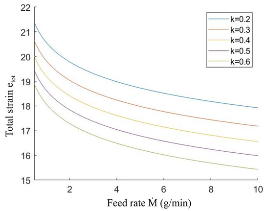
Figure 4.
Estimation of total material strain in the metal screw extrusion process as function of feed rate and screw efficiency factor k for the manufacturing of Ø1.2 AA4043-TiC wires at rpm (0.314 rad/s). The calculations were based on the strain model developed by Skorpen et al. [12].
Metal screw extrusion can be classified as a severe plastic deformation (SPD) method in terms of total strain. For comparison, one pass of equal channel angular pressing (ECAP) with pure aluminium through a 90 bend has been shown to impose a strain [17]. The total strain is thus higher in metal screw extrusion than ECAP, as aluminium materials are rarely ECAPed more than ten passes. It should be noted that SPD methods like ECAP are usually performed at lower temperatures, i.e., maximum 40% of the equilibrium melting temperature (0.4). Low temperatures restrict recovery and recrystallisation of the material. The metal screw extruded material in this study experienced a processing temperature close to 0.9 (540 ), which render possible recovery of the microstructure. Thus, nanograin structures frequently reported in the SPD literature would be unlikely to be detected for metal screw extruded materials.
Nanoparticles having a diameter <100 are highly susceptible to agglomeration in dry state due to a high surface area to volume ratio. Figure 5 shows a scanning electron microscopy image of a TiC-coated granule surface prior to metal screw extrusion. The surface is densely coated by TiC nanoparticles and agglomerates up to 400 in diameter was seen. The authors acknowledge that roll mixing of aluminium granules together with nanoparticles induce agglomeration, in addition to be a relatively inefficient method for feedstock preparation. It is believed that direct feeding of nanoparticles into the metal screw extruder could solve these challenges, and later improvements of the metal screw extruder will take this into account.
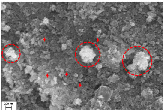
Figure 5.
SEM image of TiC nanoparticles on coated AA4043 granule after roll mixing, but before metal screw extrusion. Individual TiC nanoparticles (40–60 ) are indicated by arrows. Circles show TiC clusters up to a size of ∼400 .
3.2. Properties of Metal Screw Extruded Wire
Particles containing titanium were observed to be evenly distributed in the aluminium matrix after metal screw extrusion. An EDS map of embedded nanoparticles in the metal screw extruded AA4043-TiC wire is shown in Figure 6. The analysis was set to detect characteristic X-rays of aluminium, titanium, silicon and carbon. Carbon, a low atomic number element, has low detection accuracy in EDS. X-ray signal noise can occur due to carbon residue on the electron microscope chamber walls. The carbon element map was therefore shattered by noise and excluded from Figure 6. Titanium carbide particles could therefore not be determined directly from EDS mapping. TiC particles were instead interpreted through titanium signal not showing an overlaying silicon signal, as illustrated in Figure 6a.
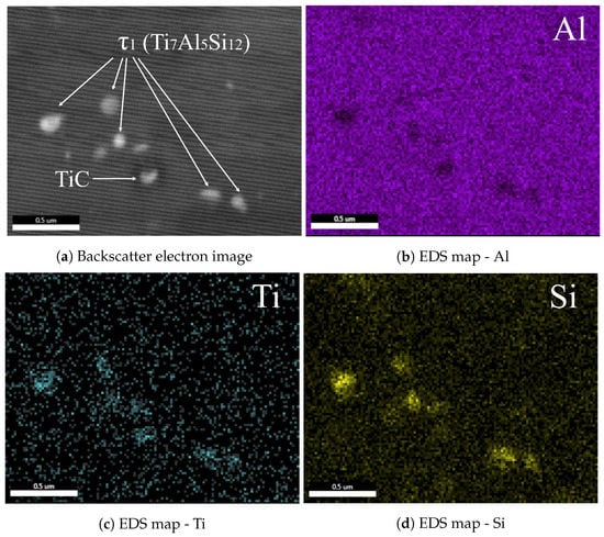
Figure 6.
EDS map of metal screw extruded AA4043-TiC feedstock wire showing presence of two different Ti-containing phases: Ti7Al5Si12 (τ1) and TiC.
Overlaying areas with titanium and silicon signals were found in the AA4043-TiC wire. Thus, it is considered likely that silicon combined with a fraction of the TiC particles and created a new phase, marked as . It is well known that silicon influences TiC particles in aluminium melts. Ding and Liu concluded that silicon enters the TiC lattice in liquid aluminium, creating a ternary Al-Si-Ti phase and AlC [18]. In addition, the absorbed silicon atoms can cause significant lattice distortion of the parent TiC.
XRD was employed to determine the phase in the AA4043-TiC wire. The resulting spectrum is shown in Figure 7. Apart from the expected aluminium and silicon signals from the matrix, the TiAlSi () phase was detected. This is in accordance with the experimental assessments of Li et al. at 550 (0.86) for very long holding times (>1000 h) [19], and the corresponding Al-Si-Ti ternary phase diagram. The reaction from TiC to TiAlSi is shown in Equation (9), which is spontaneous () at the extrusion temperature [20]. The reaction product AlC was also detected by XRD, however with low intensity. Aluminium carbide could not be detected by metallography, as AlC is easily hydrolysed during metallographic preparation in accordance to Equation (10).
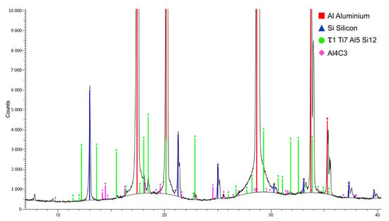
Figure 7.
XRD spectrum of the AA4043-TiC wire showing presence of the Al, Si, (TiAlSi) and AlC phases.
Apart from thermodynamic investigations for very long holding times (>1000 h), indications of silicon diffusion in TiC particles for Al-Si-TiC alloys processed in the solid state are not reported in the literature. Fattahi et al. prepared GTAW feedstock with identical alloy and nanoparticle mixture as the present study through ARB, but did not report any reactivity of TiC nanoparticles [9]. The low interpass process temperature (300 for 10 min) between each cold rolling pass was probably insufficient for diffusion of silicon into TiC particles. According to Lopez et al., annealing of an Al-7wt.%Si-10wt.%TiC alloy at 550 (0.86 ) for six hours did not reveal any reactivity between silicon and TiC [21]. However, TiC had a large mean particle size of 18 . As stated by Lekatou et al., the reactivity of TiC particles increase with decreasing size due to an increased surface area to volume ratio [22]. Severe plastic deformation can alter the reaction kinetics of TiC during metal screw extrusion. As pointed out by Sauvage et al., an increased vacancy density during SPD could increase the diffusivity of elements [23]. As stated in Section 3.1, metal screw extrusion is indeed a SPD method in terms of accumulated strain.
A chemical reaction between TiC nanoparticles and silicon did clearly happen during metal screw extrusion. In order to trace the interaction between silicon and TiC, the remaining material in the extrusion chamber (i.e., the screw plug) was investigated. A cross-section cut 2 cm away from the screw end flight was made and investigated by EDS in five positions, as illustrated by Figure 8a. The TiC/ partition was plotted against screw plug position and presented in Figure 8b. The results showed the presence of already in the compacted screw channel and at the screw tip (Positions 1 and 2, respectively). The temperature was measured to be 480 C at Positions 1 and 2 according to thermocouple data from the metal screw extruder. The combined temperature (<500 C) and deformation were therefore sufficient to initiate the TiC→ reaction in the smearing zone between the compacted screw channel and the screw plug. As can be seen from Figure 8, 30–40% of all examined particles were indeed transformed to TiAlSi in the smearing zone. The TiC/ partition saturated at a 50/50 fraction closer to the extrusion die opening, i.e., Positions 3–5. Apparently, the driving force for the reaction of TiC with silicon decreased in the extrusion chamber. The reason for this is not known. Earlier studies have shown a state of severe deformation in the smearing zone, which may kinetically favour the TiC→ transformation [12,13]. When the stress state decreases without any significant temperature increase in the extrusion chamber, any further phase transformation may cease, as seen in Figure 8b.
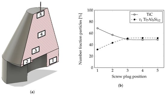
Figure 8.
Transformation of TiC into τ1 (Ti7Al5Si12) during metal screw extrusion through the compacted material in the extrusion chamber (i.e., screw plug). The TiC→τ1 transformation was most intensive in the ’smearing zone’ closest to the screw tip, i.e., Positions 1–3. (a) Model of the screw plug. Investigation plane is indicated by the hatched area. Titanium-containing phases were examined in positions labelled 1–5; (b) TiC/τ1 partition in the AA4043-TiC screw plug. Positions 1–5 are indicated in (a).
3.3. Wire Surface Quality
The surface appearance of the commercial welding wire and metal screw extruded wire is exhibited in Figure 9. The commercial wire possessed a smoother surface quality compared to the metal screw extruded counterpart. Commercial manufacturers improve the surface quality by a wire shaving procedure in the final processing steps. The sharp peeling knives remove any roughness on the wire. The screw extruded wire was in as-produced state without any shaving steps as seen in Figure 9b. The surface scratches arose primarily from a rough inner surface of the extrusion die, but also from friction forces between the die tool steel and aluminium. Post-extrusion shaving is needed to obtain an excellent surface finish.
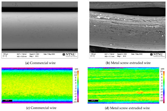
Figure 9.
Surface quality of commercial AA4043 wire and metal screw extruded AA4043-TiC wire by SEM (a,b) and profilometer measurements (c,d). The commercial AA4043 material exhibited excellent surface quality due to surface shaving, whereas the metal screw extruded counterpart possessed a rough outer surface.
The porosity content in WAAM materials is affected by the surface quality. Scratches and holes on the wire surface act as trap sites for moisture and hydrocarbon residue, which create hydrogen porosity when fused by an electric arc [24]. The principle was demonstrated by Ryan et al., who compared feedstock materials from three suppliers for WAAM and measured the amount of porosity [25]. The authors concluded wire surface quality being an important prerequisite for reducing gas porosity.
3.4. Bead-on-Plate Deposition
Macrographs of deposited wires by GMAW in transverse and longitudinal planes are shown in Figure 10a–f. The benchmark of commercial AA4043 wire possessed relatively low levels of porosity. This wire is optimised for successful arc deposition with low internal hydrogen levels and, as previously seen, excellent surface character. Thus, a relatively dense material was obtained. The AA4043 metal screw extruded wire was similar to the commercial material in terms of porosity. The circularity of the pores indicates that gas was entrapped during solidification. Such metallurgical pores are commonly caused by supersaturation of hydrogen at the advancing solid/liquid front, which precipitate as bubbles. The hydrogen content could be introduced by grit on the wire surface or incorporated in the matrix during metal screw extrusion. Recall from Figure 9b that the surface quality of metal screw extruded wires were mediocre and could possibly act as trap site for moisture and grit. These constituents are released as hydrogen bubbles upon arc deposition. Incorporated matrix hydrogen originate from aluminium granule feeding into the metal screw extruder. Due to the exposure of aluminium with air, every granule developed a thin AlO · 3HO or Al(OH) hydroxide layer [26]. The hydroxylated layer from each granule was then merged into the metal matrix by metal screw extrusion. Upon arc deposition, the hydroxide is dissociated and atomic hydrogen recombine and precipitate as H bubbles upon solidification. It is not known which hydrogen source (matrix or surface hydrogen, or a combination), which leads to the porosity content in the metal screw extruded AA4043 material.
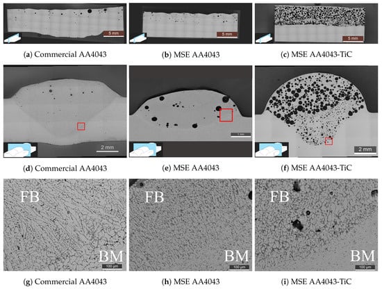
Figure 10.
Bead-on-plate GMAW deposition of investigated materials in longitudinal and transverse sections. Metal screw-extruded materials are marked MSE. Micrograph image position is indicated in (d–f) by red rectangles. FB is fusion boundary and BM is base material. AA4043 without TiC addition possessed relatively low levels of porosity and a columnar microstructure. TiC-reinforced metal screw extruded material was highly porous and possessed an equiaxed microstructure.
The pore volume becomes significantly higher when TiC is introduced. TiC nanoparticles, with a very large surface area, also react with humidity in air [27,28]. TiC-coated granules were, regrettably, not degassed prior to metal screw extrusion in order to dissolve the moisture. Thus, a material with excess of hydrogen atoms was probably produced by metal screw extrusion. It can be foreseen that a pre-treatment procedure (e.g., in vacuum at elevated temperatures) is necessary for successful production of wires by metal screw extrusion. Future research must develop methods for handling and introduction of nanopowders into the metal screw extruder.
The microstructure in the transition from fusion boundary (FB) to base material (BM) is shown for each bead-on-plate layer in Figure 10g–i. It is clear that monolithic AA4043 exhibits a columnar dendritic microstructure in the fusion zone. The columnar dendritic zone arose due to the large heat sink to the base plate, as primary aluminium dendrites tend to grow in the opposite direction of the largest heat flux. Columnar grains are more susceptible for cracking events and yield anisotropic mechanical properties [29]. An equiaxed grain morphology is therefore sought to increase the weldability of aluminium alloys. The TiC-modified AA4043 weld possessed an equiaxed grain morphology. A columnar to equiaxed transition was therefore achieved by the addition of TiC. The grain refinement was however modest, due to the relatively long distance between each potent TiC particle. The low addition of TiC (1wt.%) accompanied by the formation of the non-nucleating TiAlSi phase increased the distance between each heterogeneous nucleation event.
Several TiC particles were observed on the grain boundaries as seen in Figure 11, which is consistent with other work [8,9]. TiC particles were pushed in front of the advancing solidification front due to their lower thermal conductivity compared to liquid aluminium [30]. Enrichment of nanoparticles at grain boundaries can limit mechanical as well as corrosion properties if present in sufficient amount. A homogeneous dispersion of nanoadditions in the material after GMAW deposition should therefore be sought. In order to fulfil this requirement, nanoadditions must be engulfed by the solid-liquid growth front during solidification. Engulfment is achieved either by good wetting between the particle and liquid aluminium (low interfacial energy), or with higher thermal conductivity of the nanoparticle than liquid aluminium. In fact, the TiAlSi phase was incorporated in the matrix, Figure 11. Other work used graphene sheets with very high thermal conductivity to achieve a homogeneous dispersion in aluminium matrix composites [31]. However, the grain refining potency of nanoparticles is of great importance. Future designs of feedstock for welding and additive manufacturing could focus on hybrid additions of nanoparticles, where one part is grain refiner and one part is a strengthening phase homogeneously distributed in the aluminium matrix. Metal screw extrusion is well suited for such hybrid processing, where any mixture of particles can be added.
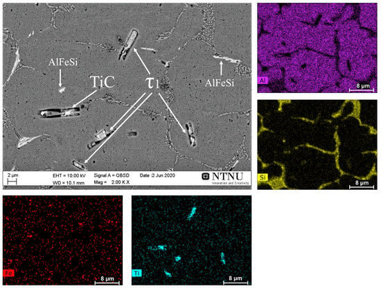
Figure 11.
EDS map of metal screw extruded AA4043-TiC after bead-on-plate deposition. Ti-containing phases and AlFeSi intermetallics are marked with white arrows. Titanium particles were mainly distributed on grain boundaries.
The measured hardness of the investigated materials after bead-on-plate deposition is shown in Figure 12. The dispersion of TiC and TiAlSi in the metal screw extruded material increased the hardness slightly. However, the hardness increase was modest due to the underlying pore structure and coarse particle size. The porosity effect on hardness is illustrated by metal screw extruded AA4043 and commercial AA4043 material. Despite an identical chemical composition and microstructure (Figure 10g,h), the hardness is 10% lower for the metal screw extruded parallel with macroporosity. Given the highly porous appearance of the AA4043-TiC specimen, the hardness would most certainly be higher for an equally dense material as the commercial counterpart.
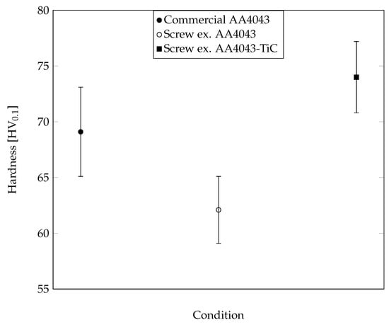
Figure 12.
Micro-hardness of bead-on-plate deposited materials. AA4043-TiC is harder than the unreinforced parallels. The AA4043-TiC structure was negatively influenced by the presence of macroporosity.
4. Conclusions and Future Work
This study has examined an alternative processing route to manufacture feedstock wire materials for additive manufacturing. The metal screw extrusion principle has been employed as a single-step process to mix, disperse and directly extrude aluminium wires reinforced with ceramic nanoparticles. An AA4043 alloy mixed with 1 wt.% TiC was successfully extruded with adequate surface quality. A solid-state chemical reaction between aluminium, silicon and TiC took place, creating a ternary intermetallic phase. Electric arc deposition of the TiC-reinforced wire showed an altered grain structure after solidification from columnar dendritic to equiaxed dendritic and enhanced hardness. A high amount of hydrogen porosity was observed in the deposited material probably due to contamination of TiC in exposure to air. Metal screw extrusion is projected to be a cost-efficient and environmentally friendly process for wire manufacturing of aluminium alloys, with few processing steps and with low energy consumption. Future work will be devoted to limit the hydrogen evolution in the materials by examining the pre-treatment of the input materials and the evacuation of the extrusion chamber with inert shield gas. Measures to improve the surface quality are also under assessment.
Author Contributions
G.L.: Investigation, Methodology, Visualization, Writing—original draft, Writing—review and editing. M.G.: Investigation, Methodology, Writing—review and editing. K.G.S.: Methodology, Validation, Writing—original draft, Writing—review and editing. T.F.: Validation, Resources, Supervision, Writing—review and editing. O.M.A.: Validation, Project administration, Supervision, Writing—review and editing. H.J.R.: Validation, Project administration, Supervision, Writing—review and editing. All authors have read and agreed to the published version of the manuscript.
Funding
This research was supported by the Research Council of Norway through grant number 272402.
Acknowledgments
Experimental support from Olav Ragnvaldsen, Pål C. Skaret and Yingda Yu is gratefully appreciated. Special thanks are directed to Norsk Hydro and in particular Oddvin Reiso and Trond Furu for their acceptance to use the metal screw extruder.
Conflicts of Interest
The authors declare no conflict of interest.
References
- Beyer, C. Strategic implications of current trends in additive manufacturing. J. Manuf. Sci. Eng. 2014, 136. [Google Scholar] [CrossRef]
- Wu, B.; Pan, Z.; Ding, D.; Cuiuri, D.; Li, H.; Xu, J.; Norrish, J. A review of the wire arc additive manufacturing of metals: Properties, defects and quality improvement. J. Manuf. Process. 2018, 35, 127–139. [Google Scholar] [CrossRef]
- Haselhuhn, A.S.; Buhr, M.W.; Wijnen, B.; Sanders, P.G.; Pearce, J.M. Structure-property relationships of common aluminum weld alloys utilized as feedstock for GMAW-based 3-D metal printing. Mater. Sci. Eng. A 2016, 673, 511–523. [Google Scholar] [CrossRef]
- Horgar, A.; Fostervoll, H.; Nyhus, B.; Ren, X.; Eriksson, M.; Akselsen, O.M. Additive manufacturing using WAAM with AA5183 wire. J. Mater. Process. Technol. 2018, 259, 68–74. [Google Scholar] [CrossRef]
- Fixter, J.; Gu, J.; Ding, J.; Williams, S.W.; Prangnell, P.B. Preliminary investigation into the suitability of 2xxx alloys for wire-arc additive manufacturing. Mater. Sci. Forum. Trans. Tech. Publ. 2017, 877, 611–616. [Google Scholar] [CrossRef]
- Martin, J.H.; Yahata, B.D.; Hundley, J.M.; Mayer, J.A.; Schaedler, T.A.; Pollock, T.M. 3D printing of high-strength aluminium alloys. Nature 2017, 549, 365–369. [Google Scholar] [CrossRef] [PubMed]
- Sales, A.; Ricketts, N.J. Effect of Scandium on Wire Arc Additive Manufacturing of 5 Series Aluminium Alloys. In Light Met 2019; Springer: Berlin/Heidelberg, Germany, 2019; pp. 1455–1461. [Google Scholar] [CrossRef]
- Sokoluk, M.; Cao, C.; Pan, S.; Li, X. Nanoparticle-enabled phase control for arc welding of unweldable aluminum alloy 7075. Nat. Commun. 2019, 10, 98. [Google Scholar] [CrossRef]
- Fattahi, M.; Mohammady, M.; Sajjadi, N.; Honarmand, M.; Fattahi, Y.; Akhavan, S. Effect of TiC nanoparticles on the microstructure and mechanical properties of gas tungsten arc welded aluminum joints. J. Mater. Process. Technol. 2015, 217, 21–29. [Google Scholar] [CrossRef]
- Fattahi, M.; Aghaei, V.N.; Dabiri, A.; Amirkhanlou, S.; Akhavan, S.; Fattahi, Y. Novel manufacturing process of nanoparticle/Al composite filler metals of tungsten inert gas welding by accumulative roll bonding. Mater. Sci. Eng. A 2015, 648, 47–50. [Google Scholar] [CrossRef]
- Werenskiold, J.C.; Auran, L.; Roven, H.J.; Ryum, N.; Reiso, O. Screw Extruder for Continous Extrusion of Materials with High Viscosity. International patent number EP2086697B1 WO2008 06307; Patent reference JP-A-2004 035 961; U.S. A-2 787 022, 1 May 2013. [Google Scholar]
- Skorpen, K.G.; Roven, H.J.; Reiso, O. A physical based empirical model for the accumulated strain in novel Metal Continuous Screw Extrusion (MCSE). J. Mater. Process. Technol. 2020, 116670. [Google Scholar] [CrossRef]
- Widerøe, F.; Welo, T. Using contrast material techniques to determine metal flow in screw extrusion of aluminium. J. Mater. Process. Technol. 2013, 213, 1007–1018. [Google Scholar] [CrossRef]
- Safra. Aluminium MIG Wires Safra 4043. DynaWeld. 2018. Available online: https://dynaweld.com.au/aluminium-mig-wire/53-safra-4043-mig-wire.html (accessed on 27 October 2020).
- Cromer, D.T.; Liberman, D.A. Anomalous dispersion calculations near to and on the long-wavelength side of an absorption edge. Acta Crystallogr. Sect. Cryst. Phys. Diffr. Theor. Gen. Crystallogr. 1981, 37, 267–268. [Google Scholar] [CrossRef]
- ISO 6507-1:2018 Metallic Materials—Vickers Hardness Test—Part 1: Test Method; International Organization for Standardization: Geneva, Switzerland, 2018.
- Furukawa, M.; Horita, Z.; Nemoto, M.; Langdon, T.G. Processing of metals by equal-channel angular pressing. J. Mater. Sci. 2001, 36, 2835–2843. [Google Scholar] [CrossRef]
- Ding, H.M.; Liu, X.F. Influence of Si on stability of TiC in Al melts. Trans. Nonferrous. Met. Soc. China 2011, 21, 1465–1472. [Google Scholar] [CrossRef]
- Li, Y.; Gu, Q.F.; Luo, Q.; Pang, Y.; Chen, S.L.; Chou, K.C.; Wang, X.L.; Li, Q. Thermodynamic investigation on phase formation in the Al–Si rich region of Al–Si–Ti system. Mater. Des. 2016, 102, 78–90. [Google Scholar] [CrossRef]
- Chen, S.H.; Li, L.Q.; Chen, Y.B. Interfacial reaction mode and its influence on tensile strength in laser joining Al alloy to Ti alloy. Mater. Sci. Technol. 2010, 26, 230–235. [Google Scholar] [CrossRef]
- Lopez, V.H.; Scoles, A.; Kennedy, A.R. The thermal stability of TiC particles in an Al7wt.% Si alloy. Mater. Sci. Eng. A 2003, 356, 316–325. [Google Scholar] [CrossRef]
- Lekatou, A.; Karantzalis, A.E.; Evangelou, A.; Gousia, V.; Kaptay, G.; Gácsi, Z.; Baumli, P.; Simon, A. Aluminium reinforced by WC and TiC nanoparticles (ex-situ) and aluminide particles (in-situ): Microstructure, wear and corrosion behaviour. Mater. Des. 2015, 65, 1121–1135. [Google Scholar] [CrossRef]
- Sauvage, X.; Wilde, G.; Divinski, S.V.; Horita, Z.; Valiev, R.Z. Grain boundaries in ultrafine grained materials processed by severe plastic deformation and related phenomena. Mater. Sci. Eng. A 2012, 540, 1–12. [Google Scholar] [CrossRef]
- Murav’ev, V.I.; Krupskii, R.F.; Fizulakov, R.A.; Demyshev, P.G. Effect of the quality of filler wire on the formation of pores in welding of titanium alloys. Weld Int. 2008, 22, 853–858. [Google Scholar] [CrossRef]
- Ryan, E.M.; Sabin, T.J.; Watts, J.F.; Whiting, M.J. The influence of build parameters and wire batch on porosity of wire and arc additive manufactured aluminium alloy 2319. J. Mater. Process. Technol. 2018, 262, 577–584. [Google Scholar] [CrossRef]
- Nylund, A.; Olefjord, I. Degassing of USGA-atomized A15Mn6Cr powder after exposure to a humid atmosphere. Mater. Sci. Eng. A 1991, 134, 1225–1228. [Google Scholar] [CrossRef]
- Merrill, P.B.; Perry, S.S.; Frantz, P.; Didziulis, S.V. Adsorption of water on TiC (100): Evidence for complex reaction and desorption pathways. J. Phys. Chem. B 1998, 102, 7606–7612. [Google Scholar] [CrossRef]
- Zhao, Y.; Dillon, A.C.; Kim, Y.H.; Heben, M.J.; Zhang, S.B. Self-catalyzed hydrogenation and dihydrogen adsorption on titanium carbide nanoparticles. Chem. Phys. Lett. 2006, 425, 273–277. [Google Scholar] [CrossRef]
- Easton, M.; Wang, H.; Grandfield, J.; St John, D.; Sweet, E. An analysis of the effect of grain refinement on the hot tearing of aluminium alloys. Mater. Forum. 2004, 28, 224–229. [Google Scholar]
- Shangguan, D.; Ahuja, S.; Stefanescu, D. An analytical model for the interaction between an insoluble particle and an advancing solid/liquid interface. Metall Trans. A 1992, 23, 669–680. [Google Scholar] [CrossRef]
- Boostani, A.F.; Tahamtan, S.; Jiang, Z.; Wei, D.; Yazdani, S.; Khosroshahi, R.A.; Mousavian, R.T.; Xu, J.; Zhang, X.; Gong, D. Enhanced tensile properties of aluminium matrix composites reinforced with graphene encapsulated SiC nanoparticles. Compos. Part A. Appl. Sci. Manuf. 2015, 68, 155–163. [Google Scholar] [CrossRef]
Publisher’s Note: MDPI stays neutral with regard to jurisdictional claims in published maps and institutional affiliations. |
© 2020 by the authors. Licensee MDPI, Basel, Switzerland. This article is an open access article distributed under the terms and conditions of the Creative Commons Attribution (CC BY) license (http://creativecommons.org/licenses/by/4.0/).