Abstract
Mg alloys are extensively used in various automotive, aerospace, and industrial applications. Their limited corrosion resistance can be enhanced by welding a thin Al plate onto the alloy surface. In this study, we perform the explosive welding of a thin Al plate, accelerated by the detonation of an explosive through a gelatin layer as a pressure-transmitting medium, onto two Mg alloy samples: Mg96Zn2Y2 alloy containing a long-period stacking ordered phase in an α-Mg matrix and commercial AZ31. The bonding interface is characterized using optical microscopy, scanning electron microscopy, X-ray diffraction, and electron probe microanalysis. Under moderate experimental conditions, the thin Al plates are successfully welded onto the Mg alloys, showing typical wavy interfaces without intermediate layers. Due to the decreased energetic condition corresponding to the use of a thin flyer plate and gelatin medium, the resulting bonding quality is better than that obtained using a regular explosive welding technique. Further, based on the well-known window for explosive welding, we estimate that the experimental conditions for successful bonding are close to the lower welding limit for a thin Al plate with the two Mg alloys considered. These findings may contribute to improving the quality of materials welded with explosive welding.
1. Introduction
Mg is the lightest among metals that have industrial uses and, thus, Mg-based alloys are extensively used in automotive, aerospace, and other applications [1]. However, Mg alloys are known to be flammable, and their mechanical properties, particularly ductility, are inferior to those of Al and its alloys. Therefore, researchers recently developed a heat-resistant Mg alloy with increased mechanical strength at elevated temperatures. The alloy structure can be described as Mg-M-RE (M = Co, Ni, Cu, Zn, or Al; RE = Y, Gd, Tb, Dy, Ho, Er, or Tm), wherein the α-Mg phase exhibits a long-period stacking order (LPSO) [2,3,4,5,6,7,8]. However, as with conventional Mg alloys, inadequate corrosion resistance limits its further application. Therefore, Mg alloys covered with a thin Al layer can yield improved corrosion resistance, and such composites may afford improved balance between strength and ductility [9].
Thus far, researchers have developed various techniques for producing Al/Mg alloy composite plates, such as laser welding [10], diffusion welding [11], friction stir welding [12], and ultrasonic welding [13,14,15]. However, because the quality of the weld joint is affected by the bonding temperature and holding time, Al/Mg tends to form intermetallic compounds at the bonding interface with heating. The formation of these intermetallic compounds can degrade the mechanical properties of the alloy [16]. In this regard, to the best of our knowledge, there is no report on the bonding of Al and Mg96Zn2Y2 alloy with ultrasonic welding.
The technique of explosive welding (EXW) can be used to solve such problems due to heating. EXW is a solid-state bonding technique that can be used to obtain metallurgical welds of two or more dissimilar metals via the acceleration of a flyer plate by the detonation of an explosive [17]. EXW is useful in solving the problem of intermetallic formation because of its short processing time; the time available is insufficient for the diffusion through welds obtained under moderate conditions near the lower limit of the weldability window [18,19]. In addition, we note that it is preferable to reduce the energy deposited at the interface because of the high reactivity of Mg; such energy reduction can suppress the formation of intermetallic compounds. The technique of underwater EXW has been developed for this purpose, and the method is effective for accelerating thin metal plates [20,21,22,23]. The formation of intermetallic compounds (or mixing zones) is associated with a kinetic energy loss ΔKE [24]. Since flyer plates used in the underwater method (including gelatin) are targeted for thicknesses (especially below 1 mm), the value of ΔKE is inevitably small. In other words, in the case of EXW through a medium, the kinetic energy loss at the collision point is smaller than that in the normal method, leading to a decrease in intermetallic compounds (or mixing zones). However, because the use of water complicates the assembly setup, we are currently developing a modified method that uses a gelatin layer instead of water as the pressure-transmitting medium [25,26,27]. With this approach, it is possible to simplify the assembly. Further, it must be noted that the weld responses under shockwaves in water and gelatin are quite similar, implying that the experimental conditions can be easily designed based on stock data of the parameters utilized for underwater EXW.
The wave shape formed at the interface is similar to those formed during EXW in air and is clearly different from that formed during underwater EXW [28]. Low collision point velocities in the horizontal direction (EXW through gelatin medium) result in a wavy or flat interface without an intermediate layer (IL). Conversely, high collision point velocities in the horizontal direction and low collision angles (underwater EXW) result in the formation of continuous or discontinuous ILs due to the rapid solidification in EXW [29]. As the formation of a continuous IL containing a brittle intermetallic compound at the bonding interface may lead to a decrease in bonding quality, the method employing a gelatin medium can be expected to suppress the formation of ILs.
In this study, a thin Al plate was bonded to extruded Mg96Zn2Y2 alloy with the use of gelatin as a pressure-transmitting medium [25,26]. Further, the bonding of an Al plate with AZ31, which is a commercially available Mg alloy, was performed for comparison. The microstructures of the recovered samples were characterized using optical microscopy (OM), scanning electron microscopy (SEM), and microfocus X-ray diffraction (XRD) analysis, and electron probe microanalysis (EPMA). Furthermore, the experimental parameters, calculated based on numerical simulations, were estimated based on the welding window and found to lie close to the lower limit of welding.
2. Materials and Methods
The experimental conditions and a schematic of the experimental assembly are presented in Table 1 and Figure 1, respectively, and the chemical composition of Mg96Zn2Y2 is listed in Table 2. In this study, we employed a parallel layer arrangement with 20 wt.% gelatin as the pressure-transmitting medium for the EXW process.

Table 1.
Experimental conditions for the explosive welding of metal and Mg alloy plates.
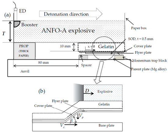
Figure 1.
Schematic of (a) the explosive welding of Al/Mg alloy plates and (b) the process of explosive welding.

Table 2.
Chemical composition of Mg alloy (wt.%).
The explosive used for welding was ANFO-A (explosion velocity: 2–2.5 km/s, density: 530 kg/m3, explosive characteristics were the same as described in [30]), which is mainly composed of ammonium nitrate and fuel oil. The explosive was detonated with the use of SEP (detonation velocity: 7 km/s, density: 1300 kg/m3, 3 g) as a booster, which was ignited by a No. 6 electric detonator (ED). The flyer plate was composed of industrially pure Al (>99%) pasted under a cover plate (0.2-mm-thick 304 stainless steel), which was used for surface protection and for decreasing momentum. The parent plate was composed of AZ31 or Mg96Zn2Y2 (5-mm thickness). The stand-off distance (SOD) between the flyer and parent plate was set at 0.5 mm. Other Mg alloy blocks (AZ31) were placed around the parent plate to act as momentum traps to reduce the cracks induced by the reflected tensile waves [22]. To stabilize the detonation velocity of the ANFO-A explosive, the welding plates were set to have a sufficient horizontal distance of >80 mm.
We estimated the experimental conditions via numerical analysis using AUTODYN-2D (Century Dynamics, a subsidiary of ANSYS, Inc., TK, USA) [20,23,31] to study the influence of certain parameters based on the welding window proposed by Wittman and Deribas [17,32].
3. Results and Discussion
3.1. Microstructure of the Weld Interface
The recovered Al/Mg96Zn2Y2 composite plate for experiment No. 6 (top view) is shown in Figure 2. We note that the Al thin plate is successfully welded onto Mg alloy by EXW through gelatin, and the upper surface appears fairly uniform and “smooth” after the EXW process. The resulting clear surface of the recovered sample has already been reported for EXW using underwater shockwaves, and a similar positive effect with the use of gelatin is confirmed by our experiments.
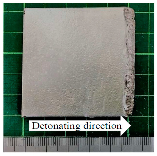
Figure 2.
Welded Al/Mg96Zn2Y2 plate (No. 6) sample.
From Table 1, we note that two experiments (No. 4 and No. 5) were unsuccessful because of the lack of energy for welding. The welding was successful in all other cases. The welding of Mg96Zn2Y2 is more difficult than that of AZ31 because of the lower strength of the former; the relevant details are discussed later in the context of the welding window.
As shown in Figure 2, a portion near the end of the Mg plate appears to have undergone shear fracture. Even with the use of momentum trap blocks, it is difficult to eliminate such shear cracks in the case of Mg96Zn2Y2 alloy, which is not ductile [33]. No such shear cracks are observed in the case of AZ31.
Figure 3 shows the microstructure of the Al/Mg alloy interface obtained with an optical microscope. The bonded interface exhibits a typical wavy structure, which is considered as evidence for successful welding based on the mechanism of explosive welding. Further, the wavelength and amplitude increase with increasing explosive thickness (Table 3). These results are similar to those obtained with regular EXW in air [34]. In addition, the wavelength and amplitude of the “waves” of explosively-welded Al/Mg96Zn2Y2 and Al/AZ31 obtained under the same explosive thickness (No. 2 and No. 6) are nearly identical (Table 3). Upon comparison with a previous result obtained for regular EXW in air by Ghaderi et al. [34] for Al/AZ31, we note that the wavelength of the wavy structure in our case is greater than 1 mm.
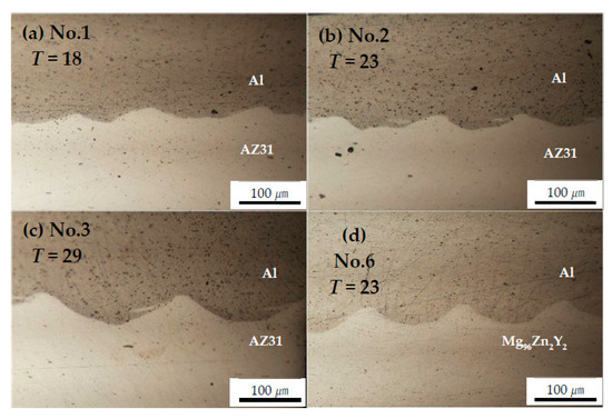
Figure 3.
Optical micrograph of the welded interface for Al/Mg alloys at x = 25 mm: (a) No. 1, (b) No. 2, (c) No. 3, and (d) No. 6.

Table 3.
Effect of explosive thickness on the formation of the wavy interface.
The use of Al thin plates and the gelatin medium in the present study causes a decrease in the energy dissipated upon collision. Therefore, the waves formed are smaller than those formed during regular EXW.
Additionally, it has been reported that an IL, which is associated with vortices, is formed during the EXW of Al/AZ31 in air and underwater [34,35]. During EXW in air, an IL is formed in a vortex confined locally at the crest of a wave, and during underwater EXW, a continuous IL tends to form along the interface. Intermetallic compounds confined in inconspicuous vortices do not affect bond strength [34,36]. In our study, IL formation was not observed clearly in any of the trials.
3.2. Quality of Bonding Across Interface
Figure 4 and Figure 5 show the results of microfocus X-ray diffraction analyses of Al/AZ31 and Al/Mg96Zn2Y2, respectively. The XRD measurements were performed using a collimator with a diameter of 50 μm. The figures show the XRD measurements (a) on the Al side 50 μm away from the interface, (b) at the center of the bonding interface, and (c) on the Mg-alloy side. As can be inferred from the figures, our attempts to measure the diffraction at the interface, including the interface region, yielded only the peak value of the metal considered for the measurement, and no peaks corresponding to the formation of intermetallic compounds were observed. This result suggests that no (or little) intermetallic compound was formed at the interface.
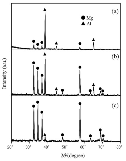
Figure 4.
Al/AZ31 (No. 2) characterized by microfocus XRD analysis: (a) Al side, (b) interface, and (c) AZ31 side.
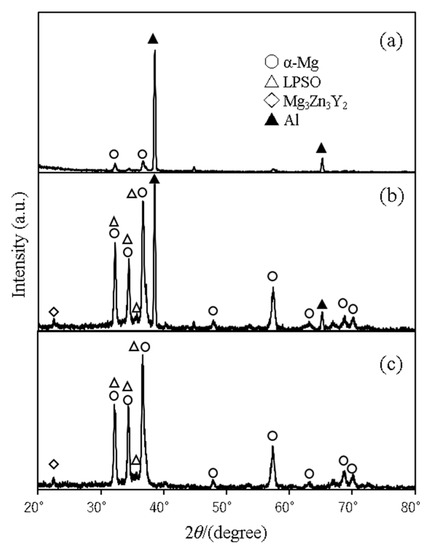
Figure 5.
Al/Mg96Zn2Y2 (No. 6) characterized by microfocus XRD analysis: (a) Al side, (b) interface, and (c) Mg96Zn2Y2 side.
The weld interface was also characterized via SEM and EPMA. The SEM images and elemental mapping of the Al/Mg alloys are shown in Figure 6 (Al/AZ31) and Figure 7 (Al/Mg96Zn2Y2). The SEM images illustrate that the composite plates show no significant diffusion or IL formation. The mapping images confirm a small melting zone, but this melting zone does not affect the bonding strength because the melting occurs only at the wave peak [34,36]. In addition, there exists a ripple-like zone close to the top of the “waves” (indicated by arrows), with a height of 10 μm or less, that appears deformed and stretched at the Mg alloy region. In a previous study [34] on the regular EXW of Al/AZ31, the presence of Al2Mg was detected in a ripple of size 200–300 μm via microfocus XRD analysis.

Figure 6.
Scanning electron microscope (SEM) image of the welded interface and elemental mapping of Al/AZ31 (No. 2) across the interface, which was acquired using electron probe microanalysis (EPMA): (a) SEM image, (b) Al mapping, and (c) Mg mapping.
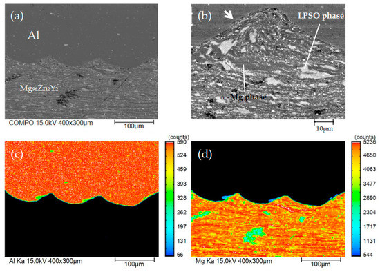
Figure 7.
Scanning electron microscope (SEM) image of the welded interface and elemental mapping of Al/Mg96Zn2Y2 (No. 6) across the interface, which was acquired using electron probe microanalysis (EPMA): (a) SEM image, (b) magnified view of the SEM image, (c) Al mapping, and (d) Mg mapping.
In this regard, Higashi et al. [15] reported the formation of a “band region,” which is considered to arise from recrystallization, as evidence of a temperature increase; however, our results did not yield such fine grains. This indicates that the processing time was fairly short, which corroborates with the lack of evidence of heating at the bonding interface.
We further measured the Vickers hardness of certain samples (Figure 8). Figure 8a,b shows the measurements under a load of 10 gf (98 mN), whereas Figure 8c shows measurements around the consolidated melt observed by mapping analysis under a load of 5 gf (49 mN). Figure 9 shows the hardness profile across the bonding interface. The Vickers hardness close to the bonded interface exhibits high values due to work hardening, and a gradual decrease in the hardness is observed with increasing distance from the interface; however, the hardness is still greater than the Vickers hardness of the as-received metals. In this regard, for the regular EXW of Al/AZ31, Ghaderi et al. [34] reported a high hardness ranging from 170 HV to 280 HV due to the existence of a large IL. In addition, similar hardness values were obtained at the Al and Mg alloy areas.
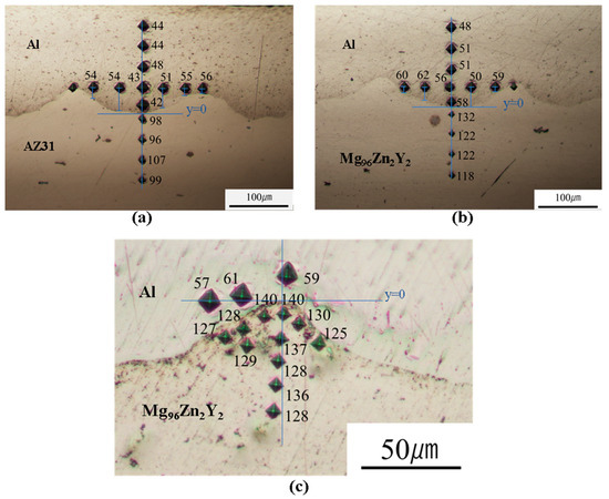
Figure 8.
Hardness distribution across the welded Al/Mg alloy interface: (a) Al/AZ31, (b) Al/Mg96Zn2Y2, and (c) Al/Mg96Zn2Y2 interface around the consolidated melt.
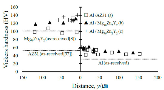
Figure 9.
Microhardness distribution near the solidified melt area. The as-received hardness of Mg alloy is referenced from existing literature [8,37], and the as-received hardness value of Al is the average measured value.
Next, to prepare a large test piece, we performed another EXW using gelatin to obtain Al/Mg96Zn2Y2 (No. 7). The recovered sample had a crack-free length of 80 mm (Figure 10). As in the case of experiment No. 6, the sheared crack at the end side could not be eliminated. The thickness of the bonded Al was only 0.2 mm, and it was difficult to measure the bonding strength directly. Because there is no general testing method for measuring the quality of welding for such composites, we performed a three-point bending test to qualitatively determine the bonding strength, which is identical to the method employed by Habib et al. [19]. Figure 11 shows a schematic of the method and the results of the three-point bending test for the Al/Mg96Zn2Y2 composite. We note that after the bending test, the composite is fractured into two pieces without showing ductile behavior; however, there is no evidence of separation at the interface (as can be inferred from Figure 11b), which implies that the bonding strength is suitably high for practical applications.

Figure 10.
Al/Mg96Zn2Y2 composite long plate (No. 7).
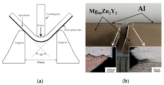
Figure 11.
(a) Schematic of the three-point bending test and (b) photograph of Al/Mg96Zn2Y2 composite long plate after the bending test.
3.3. Welding Conditions
The experimental parameters of interest for EXW are the horizontal collision point velocity, Vc, dynamic bending angle at collision, β, and flyer plate velocity, Vp [38,39]. Here, we discuss the welding conditions based on these parameters [17,32]. For the parallel assembly shown in Figure 1a, Vc is equal to the detonation velocity [39], and the following relationship holds true [38,39]:
Vp = 2Vc × sin(β/2)
Normally, the welding window is plotted based on the relationship between Vc and β. In addition, Vp is an important parameter that is directly related to the kinetic energy due to collision. We first determine the flyer plate velocity Vp For regular EXW, the equations reported by Gurney [40] and Chadwick et al. [41] as well as other equations are utilized to estimate the flyer plate velocity Vp; however, in our case, we cannot assume that the flyer mass is equal to the mass of the gelatin + cover and flyer plate, and it is more appropriate to consider the gelatin as the pressure-transmitting medium. In such a case, it is necessary to use numerical simulations, similar to case with the use of water, as reported previously [20,22,23]. Therefore, we calculated the flyer plate velocity with gelatin as the medium by using the AUTODYN-2D code.
The analytical model was developed with the shell solver for the cover and flyer plates, and the Euler solver was applied for the ANFO-A explosive and 20 wt.% gelatin. The Euler-Lagrange interaction was applied to the boundary between gelatin and the cover plate. The upper side of the interaction line interacts with the Euler boundary, whereas the lower side is calculated only for Lagrangian conditions. In other words, the shock waves propagated in gelatin act only on the surface of the cover plate. Points for the measurement of values such as velocity were set at the center position of the flyer plate. Table 4 lists the parameters [26] applied to the Mie-Gruneisen-type shock Hugoniot equation of state (EOS) for gelatin.

Table 4.
Parameters of the Mie–Gruneisen form of the shock Hugoniot equation of state [26].
Here, we note that the ANFO-A explosive can be treated as a high-pressure gas (ideal gas), on AUTODYN-2D code, and consequently, the EOS can be expressed as follows [42]:
Here, represents the pressure, the specific heat ratio, the internal energy, and the density. The subscript 0 refers to the initial condition. The initial conditions , , and are calculated using Hino’s Equation (3) [43] and express as follows: The detonation velocity of the explosive was calculated using an approximation of the experimental value given by the data reported by Hokamoto et al. [30], and the velocity change with the thickness of the explosive was considered.
Here, represents the packing density of the explosive (kg/m3), the propagation velocity of the shock wave (equal to detonation velocity, m/s), the particle velocity (m/s), c the sound velocity (m/s) of the detonation gas, and represents the polytropic index (equal to ). Further, the packing density is = 530 kg/m3.
Figure 12 shows the results of our numerical analysis of the velocity change in the flyer plate Vp as a function of vertical distance y at the center position of the sample along the welding direction (x = 25 mm). The figure indicates that the flyer plate is immediately accelerated within a very small SOD, and the velocity is > 350 m/s at y = 0.5 mm. This velocity Vp is sufficient to achieve EXW [29]. We next discuss the relevant conditions based on the welding window [17,32].
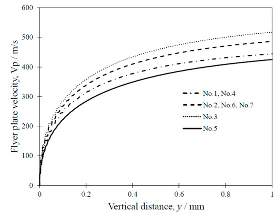
Figure 12.
Flyer plate velocity as a function of vertical distance.
Figure 13 shows the welding window for Al/Mg alloys, including the plots for the present experiments. In the present research, we do not focus on the upper limit, because the welding conditions lie closer to the lower limit, as can be observed from the figure. The lower limit can be expressed by the following formula [17,32]:
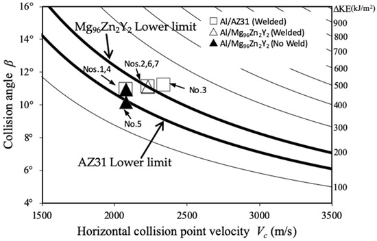
Figure 13.
Welding window for Al/Mg alloys calculated using the AUTODYN-2D code.
Here, (MPa) denotes the Vickers hardness of the hard component and a constant. The hardness values of each parent plate were obtained from the literature (AZ31: = 70, = 1780 kg/m3 [37]) and (Mg96Zn2Y2: = 101, =1890 kg/m3 [8]), and was set to 0.6 [19]. The contour lines corresponding to the kinetic energy lost due to collision are plotted in Figure 13, and we note that the lines are parallel to the lower-limit lines indicated as thick lines for welding. The kinetic energy lost due to collision, ΔKE, can be expressed by the following equation:
Here, ΔKE denotes the kinetic energy lost in the collision (kJ/m2), and and denote the masses of the cover and flyer plates per unit area (kg/m2), respectively. The calculated values of the kinetic energy loss (ΔKE) for T = 18, 23, and 29 mm are summarized in Table 5.

Table 5.
Effect of explosive thickness on kinetic energy loss.
Based on the welding window shown in Figure 13, we observe that our experimental results correspond to the window. For example, the conditions for trials No. 4 and No. 5 (Al/Mg96Zn2Y2) lie below the lower limit, suggesting that no welding occurred. In this case, Mg96Zn2Y2 alloy is not sufficiently deformed to induce fluidization, which may cause jetting and the formation of the wavy interface. The welding of Al/AZ31 is considerably easier owing to the lower hardness and strength of the Mg alloy. Furthermore, the results in this study corresponding to the weldability window and the observed interface morphology are similar to those reported by Hoseini [36] et al., which were also calculated using the Wittman and Deribas [17,32] lower-limit equations, confirming the validity of the present calculations.
4. Conclusions
In this study, we proposed and demonstrated a modified method of explosive welding using a gelatin layer as the pressure-transmitting medium to weld a thin Al plate onto AZ31 and Mg96Zn2Y2 Mg alloys. The resulting microstructure was characterized via OM, SEM, XRD, and EPMA analysis, and we confirmed that there was no significant reaction (formation of an intermediate layer) at the interface. The bonding strength at the interface was also found to be satisfactory as per the results of three-point bending tests. The experimental results were investigated based on the welding window obtained from numerical simulations, and the conditions corresponding to our experiments were found to lie close to the lower limit of welding; further, the welding conditions suitably corresponded with the experimental results. In summary, we believe that our findings can significantly contribute to advancements in explosive welding based on the use of gelatin as the pressure-transmitting medium.
Author Contributions
Conceptualization, data curation, investigation, writing—original draft: D.I.; methodology: A.M.; performed the experiments: S.T.; funding acquisition, supervision: K.H. All authors have read and agreed to the published version of the manuscript.
Funding
This research was supported by an MRC research grant program from Magnesium Research Center, Kumamoto University.
Conflicts of Interest
The authors declare that they have no conflict of interest.
References
- Mordike, B.L.; Ebert, T. Magnesium: Properties—Applications—Potential. Mater. Sci. Eng. A 2001, 302, 37–45. [Google Scholar] [CrossRef]
- Yamasaki, M.; Hashimoto, K.; Hagihara, K.; Kawamura, Y. Effect of multimodal microstructure evolution on mechanical properties of Mg–Zn–Y extruded alloy. Acta Mater. 2011, 59, 3646–3658. [Google Scholar] [CrossRef]
- Noda, M.; Mayama, T.; Kawamura, Y. Evolution of mechanical properties and microstructure in extruded Mg 96Zn2Y2 alloys by annealing. Mater. Trans. 2009, 50, 2526–2531. [Google Scholar] [CrossRef]
- Hagihara, K.; Kinoshita, A.; Sugino, Y.; Yamasaki, M.; Kawamura, Y.; Yasuda, H.Y.; Umakoshi, Y. Effect of long-period stacking ordered phase on mechanical properties of Mg97Zn1Y2 extruded alloy. Acta Mater. 2010, 58, 6282–6293. [Google Scholar] [CrossRef]
- Abe, E.; Ono, A.; Itoi, T.; Yamasaki, M.; Kawamura, Y. Polytypes of long-period stacking structures synchronized with chemical order in a dilute Mg–Zn–Y alloy. Philos. Mag. Lett. 2011, 91, 690–696. [Google Scholar] [CrossRef]
- Hagihara, K.; Yokotani, N.; Umakoshi, Y. Plastic deformation behavior of Mg12YZn with 18R long-period stacking ordered structure. Intermetallics 2010, 18, 267–276. [Google Scholar] [CrossRef]
- Kawamura, Y.; Yamasaki, M. Formation and Mechanical Properties of Mg97Zn1RE2 Alloys with Long-Period Stacking Ordered Structure. Mater. Trans. 2007, 48, 2986–2992. [Google Scholar] [CrossRef]
- Noda, M.; Kawamura, Y.; Mayama, T.; Funami, K. Thermal Stability and Mechanical Properties of Extruded Mg-Zn-Y Alloys with a Long-Period Stacking Order Phase and Plastic Deformation. In New Features on Magnesium Alloys; InTechOpen: London, UK, 2012. [Google Scholar]
- Liu, F.; Liang, W.; Li, X.; Zhao, X.; Zhang, Y.; Wang, H. Improvement of corrosion resistance of pure magnesium via vacuum pack treatment. J. Alloys Compd. 2008, 461, 399–403. [Google Scholar] [CrossRef]
- Borrisutthekul, R.; Miyashita, Y.; Mutoh, Y. Dissimilar material laser welding between magnesium alloy AZ31B and aluminum alloy A5052-O. Sci. Technol. Adv. Mater. 2005, 6, 199–204. [Google Scholar] [CrossRef]
- Mahendran, G.; Balasubramanian, V.; Senthilvelan, T. Developing diffusion bonding windows for joining AZ31B magnesium–AA2024 aluminium alloys. Mater. Des. 2009, 30, 1240–1244. [Google Scholar] [CrossRef]
- Çam, G.; Mistikoglu, S. Recent Developments in Friction Stir Welding of Al-alloys. J. Mater. Eng. Perform. 2014, 23, 1936–1953. [Google Scholar] [CrossRef]
- Kong, C.Y.; Soar, R.C.; Dickens, P.M. Optimum process parameters for ultrasonic consolidation of 3003 aluminium. J. Mater. Process. Technol. 2004, 146, 181–187. [Google Scholar] [CrossRef]
- Mariani, E.; Ghassemieh, E. Microstructure evolution of 6061 O Al alloy during ultrasonic consolidation: An insight from electron backscatter diffraction. Acta Mater. 2010, 58, 2492–2503. [Google Scholar] [CrossRef]
- Higashi, Y.; Iwamoto, C.; Kawamura, Y. Microstructure evolution and mechanical properties of extruded Mg96Zn2Y2 alloy joints with ultrasonic spot welding. Mater. Sci. Eng. A 2016, 651, 925–934. [Google Scholar] [CrossRef]
- Luo, C.; Liang, W.; Chen, Z.; Zhang, J.; Chi, C.; Yang, F. Effect of high temperature annealing and subsequent hot rolling on microstructural evolution at the bond-interface of Al/Mg/Al alloy laminated composites. Mater. Charact. 2013, 84, 34–40. [Google Scholar] [CrossRef]
- Carpenter, S.H.; Wittman, R.H. Explosion Welding. Annu. Rev. Mater. Sci. 1975, 5, 177–199. [Google Scholar] [CrossRef]
- Blazynski, T.Z. Explosive Welding, Forming, and Compaction; Applied Science: London, UK, 1983; ISBN 9401197512. [Google Scholar]
- Habib, M.A.; Keno, H.; Uchida, R.; Mori, A.; Hokamoto, K. Cladding of titanium and magnesium alloy plates using energy-controlled underwater three layer explosive welding. J. Mater. Process. Tech. 2015, 217, 310–316. [Google Scholar] [CrossRef]
- Mori, A.; Tamaru, K.; Hokamoto, K.; Fujita, M. Underwater Explosive Welding, Discussion Based on Weldable Window. AIP Conf. Proc. 2006, 845, 1543–1546. [Google Scholar]
- Mori, A.; Hokamoto, K.; Fujita, M. Characteristics of the New Explosive Welding Technique Using Underwater Shock Wave-Based on Numerical Analysis. Mater. Sci. Forum 2004, 465, 307–312. [Google Scholar] [CrossRef]
- Hokamoto, K.; Fujita, M.; Shimokawa, H.; Okugawa, H. A new method for explosive welding of Al/ZrO2 joint using regulated underwater shock wave. J. Mater. Process. Technol. 1999, 85, 175–179. [Google Scholar] [CrossRef]
- Hokamoto, K.; Nakata, K.; Mori, A.; Tsuda, S.; Tsumura, T.; Inoue, A. Dissimilar material welding of rapidly solidified foil and stainless steel plate using underwater explosive welding technique. J. Alloys Compd. 2009, 472, 507–511. [Google Scholar] [CrossRef]
- Mori, A.; Nishi, M.; Hokamoto, K. Underwater shock wave weldability window for Sn-Cu plates. J. Mater. Process. Technol. 2019, 267, 152–158. [Google Scholar]
- Nagayama, K.; Mori, Y.; Motegi, Y.; Nakahara, M. Shock hugoniot for biological materials. Shock Waves 2006, 15, 267–275. [Google Scholar] [CrossRef]
- Shepherd, C.J.; Appleby-Thomas, G.J.; Hazell, P.J.; Allsop, D.F. The dynamic behaviour of ballistic gelatin. In Proceedings of the AIP Conference Proceedings, Nashville, TN, USA, 28 June–3 July 2009; Volume 1195, pp. 1399–1402. [Google Scholar]
- Inao, D.; Tanaka, S.; Yamashita, T.; Hokamoto, K. Visualization of shockwave behavior in water and gelatin. Measurement 2019, 148, 106929. [Google Scholar] [CrossRef]
- Parchuri, P.; Kotegawa, S.; Yamamoto, H.; Ito, K.; Mori, A.; Hokamoto, K. Benefits of intermediate-layer formation at the interface of Nb/Cu and Ta/Cu explosive clads. Mater. Des. 2019, 166, 107610. [Google Scholar] [CrossRef]
- Crossland, B. Explosive Welding of Metals and Its Application; Clarendon Press: Oxford, UK; New York, NY, USA, 1982; ISBN 9780198591191. [Google Scholar]
- Hokamoto, K.; Izuma, T.; Fujita, M. New explosive welding technique to weld aluminum alloy and stainless steel plates using a stainless steel intermediate plate. Metall. Mater. Trans. A 1993, 24, 2289–2297. [Google Scholar] [CrossRef]
- Akbari Mousavi, A.A.; Al-Hassani, S.T.S. Numerical and experimental studies of the mechanism of the wavy interface formations in explosive/impact welding. J. Mech. Phys. Solids 2005, 53, 2501–2528. [Google Scholar] [CrossRef]
- Deribas, A. Physics of explosive hardening and welding. Nauk. Novosib. 1980, 220. [Google Scholar]
- Yoshimoto, S.; Yamasaki, M.; Kawamura, Y. Microstructure and Mechanical Properties of Extruded Mg-Zn-Y Alloys with 14H Long Period Ordered Structure. Mater. Trans. 2006, 47, 959–965. [Google Scholar] [CrossRef]
- Ghaderi, S.H.; Mori, A.; Hokamoto, K. Analysis of Explosively Welded Aluminum-AZ31 Magnesium Alloy Joints. Mater. Trans. 2008, 49, 1142–1147. [Google Scholar] [CrossRef]
- Bataev, I.A.; Lazurenko, D.V.; Tanaka, S.; Hokamoto, K.; Bataev, A.A.; Guo, Y.; Jorge, A.M. High cooling rates and metastable phases at the interfaces of explosively welded materials. Acta Mater. 2017, 135, 277–289. [Google Scholar] [CrossRef]
- Hoseini Athar, M.M.; Tolaminejad, B. Weldability window and the effect of interface morphology on the properties of Al/Cu/Al laminated composites fabricated by explosive welding. Mater. Des. 2015, 86, 516–525. [Google Scholar] [CrossRef]
- Ghaderi, S.H.; Mori, A.; Hokamoto, K. Explosion Joining of Magnesium Alloy AZ31 and Aluminum. Mater. Sci. Forum 2008, 566, 291–296. [Google Scholar] [CrossRef]
- Kennedy, J. Explosive Output for Driving Metal. Behav. Util. Explos. Eng. Des. 1972, 109–124. [Google Scholar]
- Cowan, G.R.; Bergmann, O.R.; Holtzman, A.H. Mechanism of Bond Zone Wave Formation in Explosion-Clad Metals. Metall. Mater. Trans. B 1971, 2, 3145–3155. [Google Scholar] [CrossRef]
- Gurney, R.W. The Initial Velocities of Fragments from Bombs, Shell, and Grenades. Army Ballist. Res. Lab Aberd. Proving Ground Md. 1943, 450. [Google Scholar]
- Chadwick, M.D.; Howd, D.; Wildsmith, G.; Cairns, J.H. Explosive welding of tubes and tube plates. Br. Weld. J. 1968, 15, 480–492. [Google Scholar]
- Liu, R.Q.; Nie, J.X.; Jiao, Q.J. Study on Lee-Tarver Model Parameters of CL-20 Explosive Ink. In Proceedings of the Smart Innovation, Systems and Technologies, Jilin, China, 18–20 July 2019; Springer: Singapore, 2019; Volume 157, pp. 205–215. [Google Scholar]
- Hino, K. Fragmentation of rock through blasting. J. Ind. Explos. Soc. Jpn. 1956, 17, 2–11. [Google Scholar]
© 2020 by the authors. Licensee MDPI, Basel, Switzerland. This article is an open access article distributed under the terms and conditions of the Creative Commons Attribution (CC BY) license (http://creativecommons.org/licenses/by/4.0/).