Abstract
Aerodynamic bearings with elastically supported tilting pads have operational properties comparable with widely-used foil journal bearings. They combine the excellent stability of tilting pad bearings, as a result of very small cross-coupling stiffness terms, with the positive properties of foil bearings, namely their ability to adapt to changing operating conditions and presence of additional damping due to friction between elastic members and bearing casings. Air cycle machines (ACMs) are used in the environmental control systems of aircrafts to manage the pressurization of the cabin. An ACM with the abovementioned type of bearings and an operational speed of 60,000 rpm was designed and successfully tested, even under conditions of strong external excitation. Some problems with rotor stability in certain operation regimes were encountered. Rotor relative vibrations measured at both bearing locations increased substantially when excitation frequency was close to the lowest rotor eigenvalues. In spite of that and the 1000 start/stop cycles passed by the end of the test, any traces of wear on the bearing sliding surfaces were negligible. When the bearing distance had to be shortened in order to insert the machine into the defined space, the rotor quickly became unstable at relatively low speeds. Although rotor stability reserve was reduced only slightly, the rotor had to be redesigned in order to achieve stability. Operation characteristics of aerodynamic bearings with elastically supported tilting pads are presented together with rotor dynamic analysis and validated with measured results.
1. Introduction
Air cycle machines (ACMs) are used in the environmental control systems of aircrafts to manage the pressurization of the cabin. To achieve small dimensions and high efficiency, the rotor should operate at a very high speed. ACM design is similar to that of a turbocharger, i.e., the rotor is driven by a turbine and pressurized air is provided by a blower impeller. The majority of contemporary high-speed rotating machines use aerodynamic foil bearings, which have very good operational properties [1,2,3,4,5,6]. However, even better functional properties can be achieved with tilting pad journal bearings (TPJBs), which have excellent dynamic characteristics. Cross-coupling stiffness terms, which are known to promote rotor instability, are found in TBJBs two orders lower than the principle stiffness terms. Rotors in TPJBs are therefore principally stable, unless there is a strong external source of excitation, such as a high-pressure labyrinth seal. With foil bearing working gap geometry, it is not possible to achieve such small values of cross-coupling stiffness terms (e.g., [7]), and this is why TPJBs are a better solution from the standpoint of rotor stability. A new type of aerodynamic bearing with elastically supported pads, which combines the advantages of foil bearings and tilting pad journal bearings, was designed and successfully used for ACM rotor support.
2. Materials and Methods
Aerodynamic tilting pad journal bearing characteristics were designed with help of the computer program code “DATPJB.” Standard bearing configuration covers three pads with static load acting symmetrically between the two lower pads. The program code “DATPJB” provides the solution of the Reynolds equation for compressible medium according to [8]. In the process of calculation, it was necessary to find the equilibrium of the pad position and static position of the journal in the bearing. Dynamic stiffness and damping coefficients were calculated for small harmonic journal movement in the vicinity of the equilibrium position, which enabled us to also determine the stability of the pad movement. The computer program “AXSPDR4,” based on principles stated in [9], was used for the design of the aerodynamic spiral groove thrust bearings, providing bearing load capacity, friction loss and film stiffness as a function of speed and film thickness.
Dynamic rotor analysis was carried out with the program “DYNROT-R,” which enable us to calculate critical speeds, response to unbalance and pertinent stability reserve. The program involved graphic superstructure, enabling easy generation of the rotor model. The program also provided graphic outputs, such as Campbell diagrams or graphic representations of rotor response to unbalance in selected sections. All computer programs are available according to standard commercial conditions.
Relative rotor vibrations during tests were measured by means of eddy current sensors Micro-epsilon S04 (Micro-Epsilon Messtechnik, Ortenburg, Germany) connected to units Micro-epsilon eddyNCDT 3300 (Micro-Epsilon Messtechnik, Ortenburg, Germany) with resolution in nanometers and bandwidth up to 100 kHz. Vibration signals were recorded by National Instrument measuring USB DAQ card with 16 analog inputs and sampling frequency up to 1.2 MHz. The card operation was controlled by the program ScopeWin NI, enabling graphic processing of measured signals and statistic elaboration of measured data, e.g., evaluating RMS values of measured data or providing frequency spectra.
External excitation was realized by mounting the ACM on a vibration table, which could provide excitation either in horizontal or in vertical directions. Maximum acceleration of the table was 2g (~20 m·s−2).
3. Results
3.1. Aerodynamic Bearings with Elastically Supported Tilting Pads
There are several patents covering bearing design [10,11], the simplest of which is illustrated in the left-hand section of Figure 1. Tilting pads 2 are supported by elastic members 4 with the shape-enabling free pad tilting in a peripheral direction. The detail of the pad elastic support is in the centre of Figure 1. The pad is held in position by the pin 3, which also enables the adjustment of basic bearing clearance by means of the nut 5. Basic bearing clearance, enabling easy run–up without excessive wear, is the most important advantage of TPJBs in comparison with foil bearings.
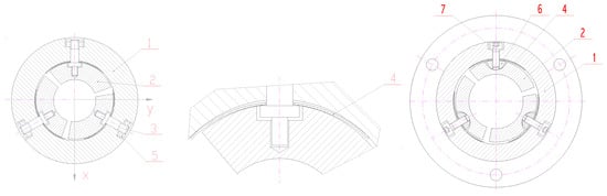
Figure 1.
Two types of TPJBs according to Czech patent specifications. 1–bearing casing, 2—pad, 3—pin, 4—elastic member, 5—nut, 6—insert, 7—screw.
Some problems with TPJBs of the simplest design may occur due to uneven deformation of the elastic member, which can result in two-point contact restraining free pad movement. That is why a more sophisticated design with defined geometry of contact between the pad and its supporting member was devised. Its design is shown in the right-hand section of Figure 1. The pad 2 is supported by the insert 6 with a curved surface, on which the pad can freely tilt in circumferential and axial directions. The insert 6 is supported by the elastic member 4; basic bearing clearance can be set by the screw 7. Dynamic bearing properties are very good due to the very small cross- coupling stiffness terms, which is a property inherent to tilting pad bearings. Thanks to elastic members the bearings also acquire properties found in foil bearings, i.e., the adaptability to changing operating parameters and additional damping due to friction of elastic members on the inner surface of the bearing body.
Dynamic characteristics of the bearings used in ACM, calculated by the method described in Section 4, are presented in Figure 2. Bearings 25 mm in diameter with l/D ratio of 0.72 were loaded with 4.4 N at the turbine (TB) and 4.9 N at the blower (DB) side, respectively.
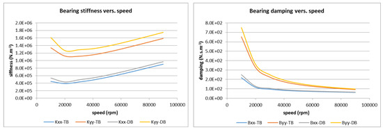
Figure 2.
Stiffness and damping coefficients of air cycle machine (ACM) bearings.
3.2. Rotor Dynamic Analysis
An ACM with aerodynamic TPJBs, designed in 2012 [12], is shown in Figure 3. The rotor 1 is supported by two TPJBs with elastically supported pads 3. Axial forces are taken up by aerodynamic spiral groove thrust bearings 4, 5. Turbine (left) and blower (right) impellers are at rotor overhang ends. Rotor relative vibrations are observed by two pairs of eddy current sensors 9, which have measuring range of 0.5 mm and typical sensitivity of 28 mV/µm.
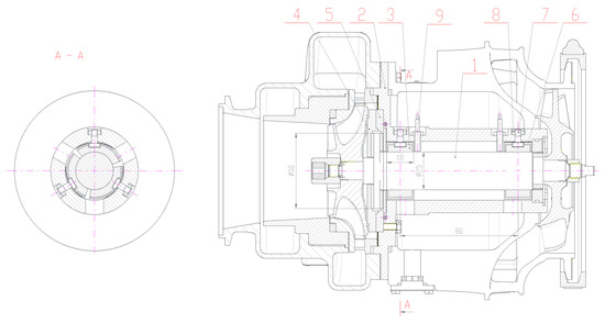
Figure 3.
Air cycle machine design. 1—rotor, 2—casing, 3—pad, 4,5—thrust bearings, 6—elastic member, 7—pin, 8—nut, 9—sensor.
Dynamic analysis of the rotor showed that there are four critical speeds associated with the rigid rotor on bearing aerodynamic film, which ranged from 7,000 to 15,500 rpm. The first bending critical speed of co-rotating precession is higher than 200,000 rpm, as can be seen from the potential intersection of the red line with the speed line in the Campbell diagram in Figure 4. The branch of the same eigenvalue with counter-rotating (backward) precession (light blue line) is not excited by unbalance and therefore it is not considered as a critical speed.
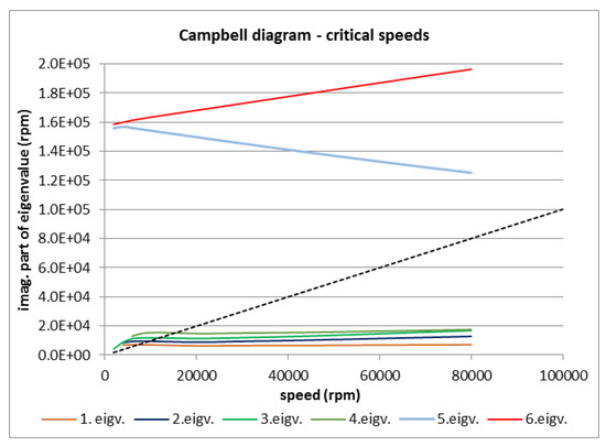
Figure 4.
Campbell diagram of critical speeds.
As can be seen in Figure 5, real parts of the four relevant eigenvalues are negative, so that the rotor operation is stable. Rotor resistance to instability is usually determined by means of logarithmic decrement, designated as log δ, defined e.g., in [13]. However, to make the situation more obvious, we can define the stability reserve of the rotor as a percentage by the following equation:
where Re (λ) and Im (λ) represent the real and imaginary part of eigenvalue respectively.
χ = log δ × 100/π= −200 × Re (λ)/Im (λ) (%),
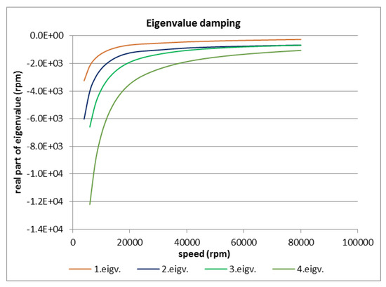
Figure 5.
Damping of the four lowest eigenvalues.
The stability reserve of the two lowest eigenvalues at operation speed of 60,000 rpm are 10% and 13.5% respectively, which correspond to logarithmic decrement of 0.31 and 0.42. Such values of stability reserve are in most cases quite sufficient. The results of rotor response to unbalance were also quite satisfactory, with only a slight increase of vibration amplitude in the region around the “bearing” critical speed from 8000 to 18,000 rpm, i.e., outside standard operating range.
3.3. Operation Tests
Operation tests were carried out in a test loop with the turbine driven by pressurized air, as in real conditions [14,15]. The machine could be operated up to 68,000 rpm with minimum values of relative rotor vibrations. As shown by the amplitude-frequency characteristics depicted in Figure 6, the RMS values of vibration amplitudes were measured in two different tests. The RMS values of vibration in radial direction in both tests were lower than 2 µm (double amplitude lower than 5 µm). The sensor at the blower side in the horizontal direction was damaged during tests, and therefore its signal was not included into the right diagram.
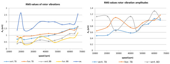
Figure 6.
RMS values of rotor vibration from the first and second test. TB/DB—turbine/blower side, vert./hor.—vertical/horizontal direction.
Typical records of rotor run-up and run-down are illustrated in Figure 7. The vibration signal in axial direction is distorted by damaged measured surface, so that only quasi-static shifts can be evaluated. Quasi-static shifts in radial directions are caused by the change of rotor axis due to thrust runner alignment according to the position of thrust bearing sliding surface. It is more evident from the rotor run-down in the right section of Figure 7, where the change of axial force direction results in relatively big deviations of the rotor in a radial direction. This phenomenon is caused by relatively low stiffness of pad supports in comparison with thrust bearing film stiffness. This by-product of elastic pad support contributes to a significant increase of thrust bearing load capacity. The average coefficient p/u (specific load, i.e., load acting on unit of sliding surface area, divided by circumferential speed on bearing pitch diameter) was exceeded by more than three times due to this possibility of sliding surface alignment.
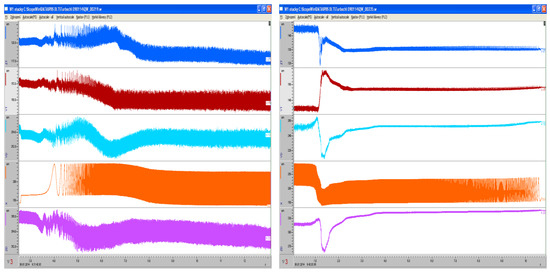
Figure 7.
Vibration amplitudes at run-up to 23,000 rpm (left) and run-down from 60,800 rpm (right). Top down: TB vertical direction, TB horizontal direction, DB horizontal direction, axial direction, DB vertical direction; maximum vibration double amplitude 10 µm at DB vertical direction.
Some tests were carried out with strong external excitation with variable frequency. Some excitation frequencies caused severe vibrations of the otherwise stable running rotor. The regimes with vibration amplitudes increased by external excitation are documented in Figure 8 for the speeds of 30,000 and 60,000 rpm. Excitation frequencies inducing severe rotor vibrations ranged from about 60 to about 200 Hz; lower or higher excitation frequencies had no adverse effect on rotor vibration. The abovementioned frequencies are in the vicinity of the four lowest eigenvalues, i.e., critical speeds of the rigid rotor on the aerodynamic bearing film.
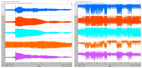
Figure 8.
Vibration amplitudes at 30,000 (left) and 60,000 rpm (right) with external excitation 2 g. Top down: TB vertical direction, TB horizontal direction, DB horizontal direction, axial direction, DB vertical direction; maximum vibration double amplitude 450 µm at DB vertical direction
At the end of test, the machine had endured 1000 start-stop cycles without any traces of excessive wear or sliding surface damage. As is illustrated by Figure 9, neither the pads nor shaft in the bearing location shows significant sliding surface damage; at the pad surface there are still visible traces of the original machining.
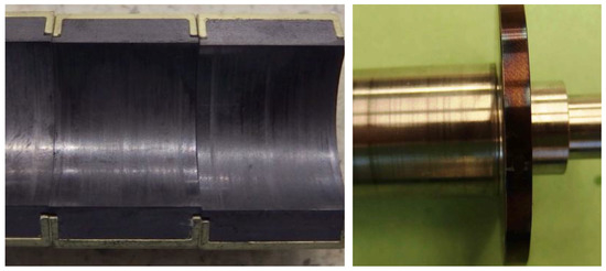
Figure 9.
Bearing pads and rotor sliding surface after test.
The problem with rotor stability appeared when the bearing span had to be reduced to assure that the machine would fit into the defined space. The rotor with a bearing span reduced from 80 to 45 mm exhibited instability already at relatively low speeds, around 30,000 rpm. This is illustrated by the vibration signals around 30,000 and 50,000 rpm in Figure 10. Very distinct subharmonic frequency components, which varied from 1/4 to 1/7 of rotational frequency, can be observed in vibration signals in Figure 10. Its frequency could be determined by comparing vibration signals with speed signals.
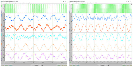
Figure 10.
Vibration amplitudes around 30,000 rpm (left) and 50,000 rpm (right). Top down: speed signal, TB vertical direction, TB horizontal direction, DB horizontal direction, axial direction, DB vertical direction; maximum vibration double amplitude 225 µm at TB in horizontal direction.
Vibration amplitudes in the region of instability were very high, reaching practically the whole bearing clearance, and it was only thanks to the elastic pad support that immediate failure did not take place. Rotor dynamic analysis carried out disclosed that, due to the bearing span reduction, the stability reserve of the lowest eigenvalue at 60,000 rpm decreased from 9.8% to 7.3%. Our experience shows that in most cases of a rotor supported in aerodynamic tilting pad journal bearings, even 5% of stability reserve is sufficient to ensure stability, but in this special case the rotor had to be redesigned to achieve stable operation.
4. Discussion
The reason for the instability of the rotor with the reduced bearing span was discovered with the help of several experiments, one of which was carried out with the blower impeller removed. The rotor without the blower impeller exhibited stable operation in the whole operating range up to 60,000 rpm. Dynamic analysis of the rotor with such geometry showed that stability reserve was increased from 7.3% to 10%, i.e., the value calculated for the rotor with the original bearing span. To achieve at least the same stability reserve as that of the rotor without the blower impeller, the thrust bearing was relocated between journal bearings so that the bearing span could be increased to 63 mm. The rotor dynamic analysis proved that this new configuration increased stability reserve of the lowest eigenvalue to 12%, which was even higher than that for original rotor with a bearing span of 80 mm. The modified rotor has therefore all the prerequisites for stable operation.
5. Conclusions
A new type of aerodynamic tilting pad bearings was used for the rotor support of an air cycle machine for aircraft cabin pressurization. Bearings with elastically supported pads were able to secure stable operation of the rotor with a mass of 0.7 kg up to a speed of 68,000 rpm. Pad elastic support leads to additional positive bearing properties, such as the possibility of adaptation to changing operating conditions, and provides additional bearing damping. Preset basic bearing clearance reduces sliding surface wear and contributes to easy run-up. Elastic pad support enables, among other features, very rapid rotor run-up to maximum speed without the danger of bearing clearance reduction due to different temperature dilations of the bearing and shaft. Similarly, as with foil bearings, vibrations from the rotor to the outside structure and vice versa are substantially damped. As a by-product of the journal bearing design, the thrust bearing load carrying capacity is increased due to the possibility of aligning the rotor axis according to the thrust bearing sliding surface position.
The above described example shows that no strict rules can be defined as concerns rotor stability. While some rotors in aerodynamic bearings exhibit stable operation with a stability reserve lower than 5% (log δ ~ 0.15), in the present case more than 7% was not sufficient. The reason for this behavior may be found in the effect of high-gyroscopic moments of impellers at both overhanging ends of the rotor. Most high-speed machines with heavy impellers overhanging the rotor end exhibit somewhat unorthodox behavior (e.g., [16]), which should be further investigated.
Acknowledgments
This work was supported by the Technology Agency of the Czech Republic under project PID TA02011295 “Verification of air bearing technology”. Many thanks to Petr Lindovský and Lukáš Chromek for performing the experiments and providing data for analysis.
Conflicts of Interest
The authors declare no conflict of interest.
References
- Agrawal, L. Foil air/gas bearing technology—an overview. Presented at the International Gas Turbine & Aeroengine Congress & Exhibition, Orlando, FL, USA, 2–5 June 1997. ASME Publication 97-GT-347. [Google Scholar]
- Howard, S.A.; Bruckner, R.J.; DellaCorte, CH.; Radil, K.C. Gas Foil Bearing Technology Advancement for Brayton Cycle Turbines. In Proceedings of the Space Technology and Applications International Forum, Albuquerque, NM, USA, 11–15 February 2007. NASA/TM-2007-214470. [Google Scholar]
- Howard, S.A.; Bruckner, R.J.; Radil, K.C. Advancement towards Oil-Free Rotorcraft Propulsion. In Proceedings of the 65th Annual Forum and Technology Display (AHS Forum 65), Grapevine, TX, USA, 27–29 May 2009. NASA/TM-2010-216094. [Google Scholar]
- National Aeronautics and Space Administration. Creating a Turbomachinery Revolution; NASA Facts; FS-2001-07-014-GRC; Glenn Research Center: Cleveland, OH, USA. Available online: https://www.nasa.gov/centers/glenn/about/fs14grc.html (accessed on 11 April 2017).
- Bruckner, J.R.; Puleo, B.J. Compliant Foil Journal Bearing Performance at Alternate Pressures and Temperatures. In Proceedings of the Turbo Expo 2008 Gas Turbine Technical Congress and Exposition, Berlin, Germany, 9–13 June 2008. NASA/TM-2008-215219. [Google Scholar]
- Leister, T.; Baum, C.H.; Seemann, W. On the Importance of Frictional Energy Dissipation in the Prevention of Undesirable Self-excited Vibration in Gas Foil Bearing Rotor Systems. In Proceedings of the SIRM 2017, Graz, Austria, 15–17 February; 2017; pp. 32–41. [Google Scholar]
- Zhao, H.; Hou, Y.; Chen, L.; Chen, Ch. Analytical study of Aerodynamic Foil Journal Bearings with Elastic Support. J. Adv. Mech. Des. Syst. Manuf. 2008, 2, 303–312. [Google Scholar] [CrossRef]
- Lund, J.V. Calculation of Stiffness and Damping Properties of Gas Bearings. ASME J. Lubr. Technol. 1968, 90, 793–803. [Google Scholar] [CrossRef]
- Whitley, S. The design of the spiral groove thrust bearings. In Proceedings of the Gas Bearing Symposium, Southampton, UK, 25–28 April 1967. Paper No. 13. [Google Scholar]
- Šimek, J. Sliding Journal Bearing. Czech Patent Specification No. 300719, 15 June 2009. [Google Scholar]
- Šimek, J. Tilting Pad Sliding Journal Bearing. Czech Patent Specification No. 304853, 22 October 2014. [Google Scholar]
- Šimek, J. Design of the Test Stand for Verification of Air Bearing Technology; Technical Report TECHLAB No. 12-420; TECHLAB: Prague, Czech Republic, 2012. [Google Scholar]
- Vance, J.; Zeidan, S.; Murphy, B. Machinery Vibration and Rotordynamics; John Wiley & Sons: Hoboken, NJ, USA, 2010. [Google Scholar]
- Šimek, J. Experimental Verification of Air Bearing Properties; Technical Report TECHLAB No. 13-413; TECHLAB: Prague, Czech Republic, 2013. [Google Scholar]
- Šimek, J. Experimental Verification of Air Bearing Properties. Phase 2; Technical Report TECHLAB No. 14-401; TECHLAB: Prague, Czech Republic, 2014. [Google Scholar]
- Šimek, J. Some interesting features of turbocharger rotor dynamics. In Proceedings of the Colloquium Dynamics of Machines, Prague, Czech Republic, 5–6 February 2013; pp. 111–116. [Google Scholar]
© 2017 by the author. Licensee MDPI, Basel, Switzerland. This article is an open access article distributed under the terms and conditions of the Creative Commons Attribution (CC BY) license (http://creativecommons.org/licenses/by/4.0/).