Abstract
Sliding bearings–rotor systems are widely present in rotating machinery structures. The dynamic behavior triggered by friction and rub-impact faults is a key factor restricting the safe and stable operation of a rotor system. Existing studies mainly focus on analyzing dynamic characteristics but rarely explore the degree of friction and rub-impact in the system. This paper takes the sliding bearing–double-disk rotor system with friction and rub-impact as the research model, and defines the concept of the rubbing ratio. It analyzes the influence of relevant structural parameters on the system. The results reveal that the system exhibits rich nonlinear dynamics. Specifically, increasing either the rotor–stator clearance or the lubricant viscosity can drive the system into a broader regime of chaotic motion, while simultaneously reducing the extent of the rub-impact contact region. As the stator stiffness increases from 107 N/m to 9 × 10⁷ N/m, the number of chaotic windows in the bifurcation diagram increases from one to three, while the maximum rubbing force rises by approximately 58% and the rubbing ratio increases from 50% to 56%. The phenomenon of coexisting attractors in the system is also revealed and analyzed. The above research results help to reveal the motion laws of this type of rotor system and have certain guiding significance for parameter matching and optimization design of the system dynamics.
1. Introduction
Rotor-bearing systems are fundamental components of rotating machinery. The continuous industrial drive for higher efficiency and operational speeds has increased the propensity for failures in these systems under complex working conditions. Among various faults, rub-impact between the rotor and stator is a common yet severe malfunction that can critically compromise system safety and operational stability, potentially leading to catastrophic failures. This issue is particularly pronounced in high-speed, heavily loaded machinery supported by sliding bearings, such as industrial gas turbines, steam turbines, centrifugal compressors, and aero-engine rotors. In such equipment, the minimal clearance between rotor and stator, combined with demanding operating conditions, makes localized rub-impact—often triggered by imbalance, misalignment, or thermal distortion—a frequent occurrence. A profound understanding of the nonlinear dynamic characteristics and evolution of such faults is therefore of significant engineering importance for preventing disasters and ensuring the long-term, safe operation of major industrial assets.
In recent years, extensive research has been conducted both domestically and internationally on faulty rotor-bearing systems, yielding numerous findings. Early foundational work focused on specific mechanisms. Shaw et al. [1] revealed that internal resonance in multi-degree-of-freedom systems can induce asynchronous partial contact motion, demonstrating extreme sensitivity to stator parameters. However, this insightful model did not incorporate fluid film forces, a primary source of instability in journal bearings. Conversely, Chang-Jian et al. [2] performed a bifurcation and chaos analysis of a rotor supported by turbulent journal bearings, but their model omitted mechanical contact, thus isolating the fluid-induced instability from rub-impact. Recognizing the importance of fault interactions, subsequent studies developed models for coupled faults. Xiang et al. [3] investigated a system with simultaneous crack, rub-impact, and oil film forces, finding that both crack depth and stator stiffness can delay oil whirl. This work highlighted the energy exchange in multi-fault systems but analyzed parameters primarily over a speed range without deeply exploring their coupled effects on the system’s bifurcation topology. Vlajic et al. [4] enriched the understanding of contact dynamics by incorporating torsional deformation and analyzing different friction models, mapping contact regions in parameter space. This study provided a detailed bifurcation analysis but was confined to a Jeffcott rotor without complex bearing forces. A significant body of work then systematically examined the influence of various design and operational parameters. Hui Ma et al. [5] quantitatively established a near-linear relationship between the eccentric phase difference in two disks and the onset speed of oil film instability. Phadatare et al. [6] employed a large deflection model to study rub-impact under a mass imbalance, charting routes to chaos via parameter variation. Zhou et al. [7] analyzed a rotor–seal system, identifying how seal clearance, length, and pressure affect stability, thereby introducing secondary fluid–structure interactions. Zhang et al. [8] focused on a high-speed turbocharger rotor with floating ring bearings, revealing that imbalances can create stable windows between oil whirl regimes. Collectively, studies like [5,6,7,8] underscored system sensitivity to specific parameters but often treated them in relative isolation. The interaction between the two primary faults—rub-impact and oil film instability—has received focused attention. Xiang et al. [9] and Hu et al. [10] conducted complementary numerical and experimental studies on asymmetric double-disk systems. They reported the counter-intuitive phenomenon that increasing imbalance or stator stiffness could suppress oil whirl (but not whip), offering valuable diagnostic insight. A key limitation, however, was that parameters like eccentricity and stiffness were varied independently to observe system response, without formulating their synergistic coupling with the fundamental variable—rotational speed. Research further diversified into systems with different supporting elements and fault conditions. Zeng [11] analyzed a system with rolling bearings, considering Hertzian contact and varying compliance vibration. Liu et al. [12] and Qin et al. [13] focused on oil film bearing systems, analyzing the effects of eccentricity and lubricant viscosity, respectively, confirming their roles in stabilizing response and reducing rub-impact force. Zhang et al. [14] and Yin et al. [15] investigated systems with misalignment and active magnetic bearings, respectively, introducing more complex fault couplings and control–structure interactions. Cao et al. [16] highlighted the impact of inter-shaft bearing waviness on dual-rotor system dynamics, adding manufacturing imperfection as a factor. Gao et al. [17] introduced stochastic disturbances, a crucial step towards real-world uncertainty, showing its suppressive effect on nonlinear response. Parallel advancements in related fields, such as the dynamic electromagnetic scattering analysis of tiltrotor [18] and morphing quadrotor aircraft [19], underscore the growing emphasis on modeling complex, coupled multi-physics systems with moving boundaries. Most recently, the field has seen significant strides towards higher-fidelity modeling. Jin et al. [20] presented a comprehensive numerical and experimental study of an aero-engine dual-rotor system with inter-shaft bearing nonlinearity and aerodynamic excitation, identifying distinct sources of chaos at different speeds. Zhang et al. [21] introduced a novel vibration energy analysis framework, quantifying how rub-impact faults alter energy dissipation and utilization efficiency, linking a nonlinear response directly to system performance. Liu et al. [22] modeled the dangerous propagation of bearing faults through vibration interaction, revealing how health degradation can cascade. Fasihi et al. [23] reinforced the complex dynamics inherent in asymmetric rotors under contact. Zhang, J. et al. [24] employed a combined differential transform–finite difference approach to solve for gas film forces, and analyzed the dynamic response of a rotor system supported by gas bearings using the Newmark method. Their results indicate the presence of limit cycle motion under autonomous conditions and half-speed whirl in the non-autonomous regime.
However, despite the increasing sophistication of models and the deepening mechanistic understanding in these studies, a notable commonality persists: the predominant focus remains on analyzing response characteristics or on the intricacies of modeling itself. For prevalent coupled faults such as rotor–stator rub-impact, there is still a lack of a universal metric that can directly and succinctly quantify the severity of contact—encompassing aspects like intensity, temporal duty cycle, and spatial extent. Furthermore, a systematic elucidation of how this quantitative metric interacts with the coupled influence of key system design parameters is yet to be established. Moreover, discussions on the influence of different paths and initial values on the system are relatively scarce, and the research on the coexistence phenomenon of the rotor system is not very in-depth. This work not only introduces the “ friction duty cycle “ and “maximum friction force” as core quantitative metrics but also places particular emphasis on systematically elucidating how parameters such as the rotor–stator clearance, lubricant viscosity, and stator stiffness collectively influence the system’s dynamic characteristics. Furthermore, it provides a systematic analysis of coexisting dynamic phenomena. Together, these contributions establish a quantitative foundation for condition monitoring and the proactive design of such systems.
This study establishes a dynamic model for a double-disk rotor-bearing system that incorporates the coupled effects of nonlinear oil film forces and rub-impact. The governing equations are solved numerically using the fourth-order Runge–Kutta method. A systematic investigation is conducted to elucidate the relationship between the system’s nonlinear dynamic response and key parameters, including the clearance threshold, lubricant viscosity, and stator stiffness. The analysis focuses on characterizing the rub-impact behavior by determining the contact duration, the number of impact events, and the distribution of contact points along the stator. Furthermore, the severity of the rub-impact is quantified through the integrated analysis of the peak friction force and the duty cycle. The phenomenon of coexisting attractors in the system is also revealed and analyzed. These findings provide a theoretical foundation for fault diagnosis and the optimized design of rotor-bearing systems where oil film instability and rub-impact are interrelated.
2. Mathematical Model
2.1. Model of Rotor-Bearing System
In this paper, a lumped parameter model is used to represent the two-disk rotor-bearing system with friction–film force coupling, which can reflect the basic dynamic behavior of the two-disk rotor-bearing system. As shown in Figure 1a, both ends of the turntable are supported by symmetric plain bearings, where
and
are the concentrated mass of the rotor at both ends of the plain bearings,
and
are the concentrated mass of the rotor at the two turntables.
and
represent the mass eccentricity of the two turntables, respectively;
represents the stiffness of the rotating shaft;
represents the friction stiffness of the stator;
and
are the damping of the rotor at both ends of the plain bearings, and
and
are the damping of the rotor at two turntables, respectively.
and
are the geometric centers of the sliding bearings at both ends,
and
are the geometric centers of the two turntables, respectively. The radius of both ends of the plain bearing is
, the bearing clearance is
, and the length is
.
is the oil film force on the rotating shaft and
is the friction force between the rotating disk and the stator.
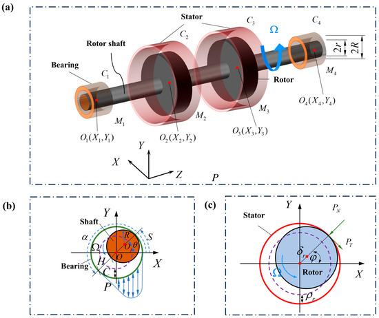
Figure 1.
Mechanical schematic of rotor-bearing system with rub-impact fault. (a) Schematic model of rotor-bearing system with two disks. (b) Model of oil film force. (c) Model of rub-impact force.
2.2. Model of Oil Film Forces
As shown in Figure 1b, the double-disk rotor system is supported by sliding bearings at both ends. The oil film force is calculated using the short bearing theory. Under the conditions of laminar flow and isothermal lubrication, the calculation of the oil film force refers to reference [25]. Equation (1) illustrates the Reynolds equation expression of the oil film force.
where
represents the tangential velocity of the rotating shaft and rotating shaft radial displacement;
, respectively, represent the distribution of oil film pressure, the oil film thickness, the angular displacement, the axial displacement of the journal, and the lubricating oil viscosity. Through dimensionless transformation, the following equation can be obtained [26,27].
where
is the bearing length;
is the dimensionless axial coordinate axis;
is the dimensionless circumferential displacement of the rotating shaft;
is the dimensionless oil film thickness; and
is the dimensionless oil film pressure. Based on the geometric relationship, it is possible to calculate
where
is the dimensionless radial displacements of the journal.
According to the short bearing theory, and substituting
into Equation (2), the nondimensional Reynolds equation can be obtained.
Then, the distribution of dimensionless oil film pressure
is given as
In this study, the half-Sommerfeld model was employed to handle the negative pressure issue. Specifically, in the numerical integration, the pressure in all negative pressure regions was set to 0. The extension of the lubricating film is assumed to correspond to the interval
. Here
is defined as the initial angle of the positive oil film pressure, which can be written as
Furthermore, the total oil film pressure can be calculated as
Substituting Equation (4) into Equation (6), the dimensionless oil film force
and
can be obtained as follows:
where
is the Sommerfeld number. To calculate the integral, it can be rewritten as
where
are expressed as
Based on the Leibniz integral rule,
and
are introduced to determine the above three variables. Then
are calculated as
Substituting Equation (10) into Equation (8), the ultimately dimensionless oil film force
and
can be calculated as follows
where
are calculated as
2.3. Rub-Impact Forces
The friction force model of the rotor-bearing system is shown in Figure 1, where
is the radial displacement of the rotor and
is the radial clearance between the rotor and the stator. When the radial displacement of the rotor is greater than the gap between the rotor and the stator, the rotor will impact, resulting in friction force.
indicates the normal friction force,
indicates the tangential friction force. Because the time of collision is very short and the deformation can be regarded as linear deformation, the collision conforms to Coulomb’s law.
When the rotor collides with the stator,
and
can be represented as follows:
In order to facilitate calculation and modeling, the normal impact force
and tangential impact force
are decomposed along the
axis and
axis of the rectangular coordinate system to obtain
Because
, we obtain
where
is the radial displacement of the rotor,
and
, respectively, are the displacement of the center of the two turntables in the direction of the
axis and
axis, and
is the friction coefficient.
2.4. Differential Equation of System Motion
As shown in Figure 1, based on the dynamics model of the rotor-bearing system, the motion equation of the system can be derived using the Lagrange equation.
where
are the radial displacement of the left and right plain bearings and
are the central radial displacement of the two turntables.
is the rub-impact force of rotor and stator and
is the nonlinear oil film force. Taking into account the combined effect of frictional force and oil film force, the following dimensionless parameters are introduced.
,
,
,
,
,
,
,
;
,
,
,
,
.
The dimensionless dynamic differential equation of the rotor-bearing system can be expressed as
3. Defining the Poincaré Map, Rub-Impact Force, and Duty Cycle
In order to better characterize different types of periodic friction vibration, this paper uses
to study the dynamic characteristics of the double-disk rotor-bearing system, where
represents the number of rotor and stator collisions in a movement period of the rotor system (
).
represents the number of rotations of the rotor system in one movement period
. For example,
indicates that there is no collision between the rotor and the stator, and the system experiences non-collision friction movement, that is, the radial displacement of the center of the turntable is less than the gap between the turntable and the stator. In order to better study the dynamic behavior of the two-disk rotor system and analyze its vibration type, the value of
was calculated and the following two Poincaré cross sections were defined by G W Luo et al. [28].
By combining the above two Poincaré sections
and
, the collision number
and rotor rotation cycle number
of the rotor system can be identified.
In order to more accurately describe the degree of friction between rotor and stator, the maximum friction force (represented by
in this paper) and friction duty ratio (represented by DC in this paper) are introduced. The maximum friction force represents the maximum force generated when the rotor and the stator collide. The duty cycle represents the ratio of the time during which the system is in a frictional contact state to the total cycle time within a complete motion cycle. In this paper, the maximum value of the vertical and horizontal friction force between the rotor and the stator in a movement cycle is defined as
, that is
The duty cycle in this paper refers to the sum of the time occupied by the rotor system and the stator in each friction stage in a movement cycle
and the ratio of the movement cycle
, that is
4. Model Validation
This paper uses the same sliding bearing as in reference [13] and conducts numerical simulation to calculate the dynamic response of the rotor system within the same speed range interval. The relevant parameters from reference [13] are adopted to verify the accuracy of the model and the feasibility of the method in this paper. As shown in Figure 2, the period bifurcation diagram of the rotor system, the displacement–velocity phase diagram of the rotor, and the Poincaré map have been provided. Figure 2a and Figure 2b, respectively, represent the research results of this paper and the calculation results of QIN. Through comparison, the calculated results of this paper are in good agreement with the research results of QIN, indicating the correctness of the modeling and the feasibility of the method.
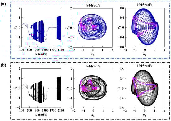
Figure 2.
Period bifurcation diagram of the rotor system and the displacement–velocity phase diagram of the rotor. (a) The results of this article. (b) The calculation results from reference [13].
5. Nonlinear Dynamic Analysis
Due to the strong nonlinear characteristics of both the friction force and the oil film force within the rotor system, the system’s dynamic response exhibits a high degree of complexity and variety. Utilizing the parameters listed in Table 1 to solve the aforementioned strongly nonlinear coupled system of motion differential equations (Equation (17)), numerical integration was performed using the fourth-order Runge–Kutta method. To ensure computational accuracy and capture the potential high-frequency dynamic behaviors of the system, the integration time step Δt was set to π/2000, meaning at least 4000 sampling points per rotor revolution. For each parameter condition (e.g., rotational speed ω), the total simulation duration corresponded to 4000 complete rotation cycles. To obtain the steady-state system response and eliminate the influence of initial transients, the data from the first 500 cycles were discarded during analysis. Only the subsequent steady-state data were used for plotting and analysis, including the periodic bifurcation diagram, the rub-impact bifurcation diagram, the maximum rub-impact force diagram, the duty cycle diagram, the rotor orbit, the time series diagram, and the Poincaré map. When constructing bifurcation diagrams, the parameter was varied continuously, with the steady-state solution from the previous parameter value serving as the initial condition for integration at the next parameter value.

Table 1.
Simulated model parameters of rotor-bearing system.
5.1. Response of Rotor-Bearing System with Varying Rotating Speed
The basic parameters of the system are shown in Table 1. Based on the set parameters, the influence of changes in a certain structural parameter on the system response is analyzed. The main idea and framework of the analysis method in this article are shown in Figure 3.
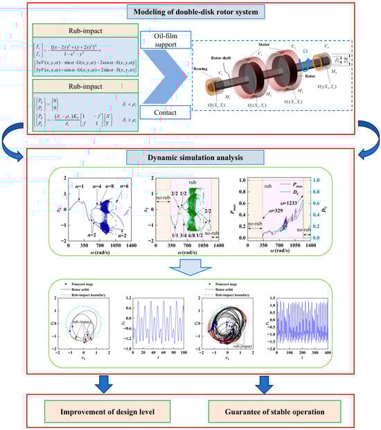
Figure 3.
Analysis method and research framework diagram.
In order to better analyze the basic dynamic characteristics of the system, this subsection mainly introduces the influence of rotational speed changes on the system. The periodic bifurcation diagram, rub-impact bifurcation diagram, maximum rub-impact force diagram, duty cycle diagram, rotor orbit, time series diagram, and Poincaré map of the double-disk rotor–slider bearing system with contact force–oil film force coupling are obtained based on the simulation of the parameters in Table 1, as shown in Figure 4. The periodic bifurcation diagram of the rotor system is illustrated in Figure 4a. It is evident that with the increase in speed, the system undergoes a sequence of motions: P1 (period 1 motion)–P2–P1–P2–P4–P8–chaos–multi-period motion–P2–P1. Figure 4b shows that the rub-impact bifurcation diagram of the rotor system more intuitively represents the number of collision responses between the rotor and the stator. With the increase in the rotational speed of the system, the evolution process of collision vibration of various cycles is as follows: 0/1(period 1 non-impact motion)–1/1–2/2–1/2–3/4–6/8–chaos–multi-period multi-impact motion–2/2–non-impact motion. Figure 4c also describes the intensity of the rotor system’s impact by examining the peak rub-impact friction force alongside the friction time’s duty cycle. To enhance the understanding of the system’s dynamic characteristics, the analysis was performed by integrating the rotor orbit diagram, the Poincaré map, and the time series shown in Figure 5, under various rotational speeds.
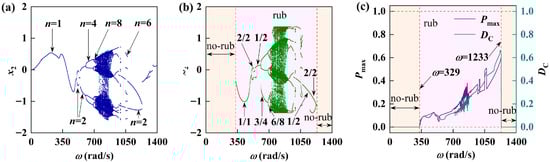
Figure 4.
Vibration response of the rotor-bearing system. (a) Periodic bifurcation diagram; (b) rub-impact bifurcation diagram; (c) maximum rub-impact force diagram and duty cycle diagram.
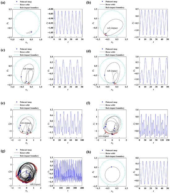
Figure 5.
Rotor orbit, Poincaré map, and time series under varying rotating speeds: (a)
, 0/1 motion; (b)
, 1/1 motion; (c)
, 2/2 motion; (d)
, 1/2 motion; (e)
, 3/4 motion; (f)
, 6/8 motion; (g)
, chaos; (h)
, 0/1 motion.
When
is the lower speed, the system moves as P1 (period 1) motion. Combined with Figure 4b,c, it can be seen that its maximum friction force and duty cycle are both 0. At this time, the system is of class 0/1 periodic vibration, and the rotor does not impact with the stator. The time series diagram shows a waveform of equal height: as the rotational speed continues to increase, the amplitude of the system vibration increases and the rotor and stator collision occurs between the system from 0/1 motion relocated to 1/1 motion shown in Figure 5a. Figure 5b shows the response of the 1/1 motion at
, it can be seen that for the system and the boundary of the occurrence of a collision impact (light red area) when the speed further increases, the system changes from 1/1 motion to 2/2 motion through the multiplier bifurcation, and the system response is shown in Figure 5c. The rotor orbit crosses the boundary and collides with the stator twice. When the rotational speed continued to rise, the system experienced reverse multiplier bifurcation into 1/1 motion, and then into 2/2 motion after the grazing bifurcation shifted to 1/2 motion, and the corresponding response is shown in Figure 5d. The Poincaré map was shown as two independent points, the rotor orbit crossed the boundary once, and the time series was shown as the cycle of two equiheight waveforms. After that, the system entered 3/4 movement again, and the corresponding response is shown in Figure 5e. The rotor and the stator collided three times. Subsequently, the system transitioned into 6/8 motion through the multiplier bifurcation, as shown in Figure 5f. The rotor orbit crossed the boundary six times. The Poincaré map is shown as eight independent points, and the time series is shown as eight waveform cycles of equal height. When the speed increases to
, it can be seen from Figure 5g, the rotor orbit is very irregular and crosses the friction boundary many times and the Poincaré map is a chaotic point. At this time, the system gradually enters chaotic motion through a series of multiplier bifurcations, and the system movement in this region is very unstable. It can be seen from Figure 4c that the degree of friction between the rotor and the stator increases and the proportion of the maximum friction force and friction time increases. Then the system gradually shifted to multi-period and multi-collision motion, and when the speed continued to increase to
, the system shifted to non-impact motion again, and its response is shown in Figure 5h. The rotor orbit did not cross the boundary, and the rotor orbit is a single circle, while the time history graph is a cyclic pattern of equal-height waves. As shown in Figure 4c, the maximum friction force is 0 and the duty cycle is 0, which indicates that no frictional contact occurred at this time. This phenomenon is also consistent with Figure 5h, verifying the correctness of the theoretical model. Based on the above analysis, it is evident that the rotational speed significantly influences the system’s dynamic characteristics, particularly with respect to rotor–stator rubbing. This highlights the role of centrifugal forces induced by rotational speed, as well as the importance of initial conditions as key factors affecting the nonlinear dynamic response.
5.2. Influence of Different Rotor–Stator Clearances
Section 5.1 mainly analyzes the basic dynamic characteristics of the rotor system and explores the impact of speed changes on the system response. Next, we will investigate the dynamic characteristics of the system by varying different structural parameters. It can be seen from Equation (15) that the clearance between the rotor and the stator will have a direct impact on the system response. Therefore, discrete values are taken for the clearance between different rotors and stators to calculate the impact of different rotor–stator clearances values on the system response. Figure 6 and Figure 7 give the corresponding system responses of two groups of rotor–stator clearances, and make a comparative analysis based on
in Figure 4. The clearance between the rotor and the stator is relatively small (
), and there is a large chaotic motion region in the medium–high speed region as shown in Figure 6. The friction impact in this region is severe, the proportion of the maximum friction force and the time of friction impact increases, and there is a strong fluctuation. The non-friction area of the system is greatly reduced (the light-yellow area), and the dynamic characteristics of the system tend to be complicated. The life and smooth operation of the rotor system are seriously affected. When the clearance between the rotor and the stator is large (
), as shown in Figure 7, the movement of the system gradually becomes simple and mainly periodic. The evolution process of impact vibration of various cycles is as follows: non-impact motion–2/8 motion–1/4 motion–1/2 motion–2/2 motion–non-impact motion. Friction occurs only in the interval at
, where the proportion of maximum friction force and time decreases sharply.
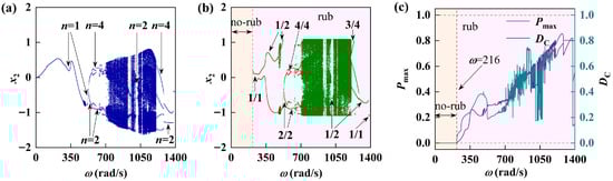
Figure 6.
The vibration response of rotor-bearing system at
: (a) periodic bifurcation diagram; (b) rub-impact bifurcation diagram; (c) maximum rub-impact force diagram and duty cycle diagram.
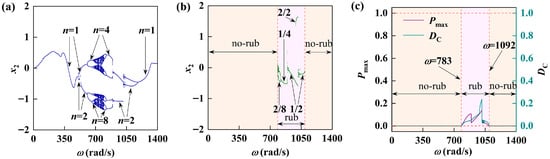
Figure 7.
The vibration response of rotor-bearing system at
: (a) periodic bifurcation diagram; (b) rub-impact bifurcation diagram; (c) maximum rub-impact force diagram and duty cycle diagram.
The influence of the clearance between the rotor and the stator on the rotation subsystem is further studied. The clearance between the rotor and the stator is discretely valued when the speed is
. Figure 8 shows the dynamic changes in the rotor orbit, Poincaré map, and time series diagram under the influence of three different clearances between the rotor and the stator. In the case of a small clearance (
), the Poincaré map showed an irregular discrete distribution. At this time, the system was in a chaotic motion state, and its rotor orbit crossed the boundary many times, causing serious friction collisions and low stability of the rotor system. At the same rotational speed, when the clearance is larger (
), the rotor system shows 1/2 motion. At this time, the rotor and the stator only rub against each other once. As the clearance further increases (
), the system shows 0/2 motion. The rotor orbit has not crossed the boundary and there is no rubbing. This indicates that the increase in the gap can prevent the rotor from taking the path to chaos at a higher rotational speed. Increasing the stator clearance can affect system efficiency, yet within a certain range, a larger clearance helps mitigate rotor–stator rubbing.
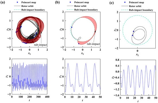
Figure 8.
Rotor orbit, Poincaré map, and time series under varying clearances between rotor and stator at
: (a)
, chaos, (b)
, 1/2 motion, (c)
, 0/2 motion.
5.3. Influence of Different Lubricating Oil Viscosity
Figure 9 and Figure 10 show the system response corresponding to the two groups of different lubricating oil viscosity values. A comparative analysis combined with
in Figure 4 reveals that the lubricant viscosity has a greater influence on the degree of friction which impacts the type of motion and bifurcation characteristics of the system. When the lubricating oil viscosity is relatively small (
), it can be seen from Figure 9a that the system has a typical Hopf bifurcation at
, and there is a large chaotic motion region in the medium–high speed range and the vibration amplitude of the system is large. Meanwhile, combined with Figure 9b,c, it can be observed that the friction in this region is severe. The maximum friction force and the time of friction impact are relatively large and have strong fluctuations; most of the system is in the state of friction impact, which is not conducive to the smooth operation of the rotor system. As shown in Figure 10, when the viscosity of the lubricating oil increases to
, the rotor system mainly exhibits periodic motion and the chaotic motion disappears. The number and intensity of the collisions between the rotor and the stator significantly decrease, indicating that appropriately increasing the viscosity of the lubricating oil is beneficial for the stable operation of the rotor system.
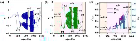
Figure 9.
The vibration response of the rotor-bearing system at
: (a) periodic bifurcation diagram; (b) rub-impact bifurcation diagram; (c) maximum rub-impact force diagram and duty cycle diagram.
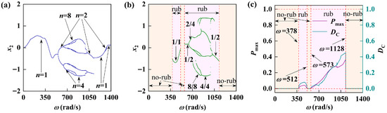
Figure 10.
The vibration response of the rotor-bearing system at
: (a) periodic bifurcation diagram; (b) rub-impact bifurcation diagram; (c) maximum rub-impact force diagram and duty cycle diagram.
The influence of lubricating oil viscosity on the rotating subsystem was further studied. When the rotational speed
was selected, the lubricating oil viscosity was discretely valued, and the lubricating oil viscosity was 0.005, 0.018, and
, to obtain the dynamic changes in the rotor orbit, Poincaré map, and time series diagram under the influence of three different lubricating oil viscosity as shown in Figure 11. In the case of a low lubricating oil viscosity (
), as shown in Figure 11a, the Poincaré map is a closed curve composed of many points, and the rotor orbit forms a multi-layer curve with regular and gradual changes within a certain space range. At this time, the system is in a quasi-periodic motion state and its rotor orbit crosses the boundary many times, resulting in more friction encounters. The stability of the rotor system is low. At the same speed, when the lubricating oil viscosity is large (
), the system shows 1/1 motion. It can be seen from Figure 11b that the rotor orbit crosses the boundary only once, which means that the rotor and the stator collide once, and the degree of friction is greatly reduced. With the further increase in lubricating oil viscosity (
), the system shows 1/1 motion at this time, and the rotor and stator have a friction collision, but the friction collision area is significantly lower than that when the lubricating oil viscosity is
, indicating that an appropriate increase in lubricating oil viscosity can restrain the system instability to a certain extent. The main reason is that high-viscosity lubricating oil can provide stronger linear damping to dissipate vibration energy.
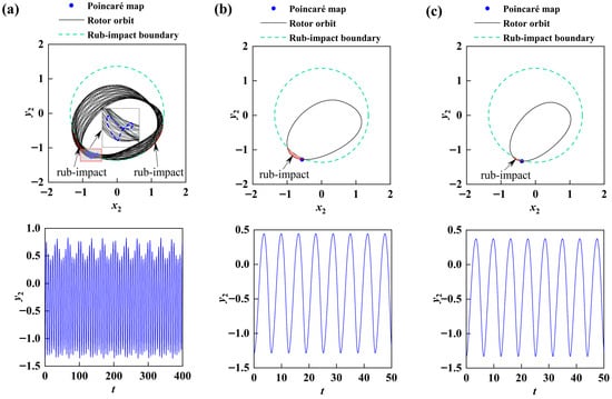
Figure 11.
Rotor orbit, Poincaré map, and time series under varying oil viscosities at
: (a)
, quasi-periodic motion; (b)
, 1/1 motion; (c)
, 1/1 motion.
5.4. Influence of Different Stator Stiffness
This paper presents the concept of stator stiffness, which correlates with the intensity of friction impact force. The findings indicate that stator stiffness significantly influences the dynamic response analysis of the rotor system experiencing friction impact. The system responses corresponding to two sets of different stator stiffness values are given in Figure 12 and Figure 13 and compared with
in Figure 4. When the stator stiffness is relatively small (
), it can be seen from Figure 12a that the system is dominated by periodic motion with a small chaotic motion region. Meanwhile, combined with Figure 12b,c, it can be observed that the system encounters friction in the
region. When the stator stiffness increases to
, as shown in Figure 13a, the chaotic motion region of the rotor system increases and the system motion becomes more complex. As can be seen from Figure 13b,c, friction occurs in the system after the rotational speed of
, and the friction region greatly increases compared with the previous two smaller stator stiffness values. Additionally, the proportion of the maximum friction force and friction time corresponding to the chaotic motion also increases sharply and shows a large fluctuation.
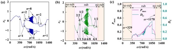
Figure 12.
The vibration response of rotor-bearing system at
: (a) periodic bifurcation diagram; (b) rub-impact bifurcation diagram; (c) maximum rub-impact force diagram and duty cycle diagram.
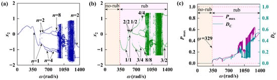
Figure 13.
The vibration response of rotor-bearing system at
: (a) periodic bifurcation diagram; (b) rub-impact bifurcation diagram; (c) maximum rub-impact force diagram and duty cycle diagram.
The influence of the stator stiffness on the rotating subsystem was further studied. When the rotating speed was
the stator stiffness was discretely evaluated, and the stator stiffness was
,
, and
. The dynamic changes in the rotor orbit, Poincaré map, and time series diagram under the influence of three different stator stiffnesses were obtained as shown in Figure 14. When the stator stiffness is small (
), as shown in Figure 14a, the system shows 0/1 motion at this time, and the Poincaré map is an independent point, while the rotor orbit does not cross the boundary, indicating that no friction occurs. At the same speed, when the stator stiffness is large (
), the system shows 2/2 motion. It can be seen from Figure 14b that the rotor orbit crosses the boundary twice, which means that the rotor and the stator collide twice and the degree of friction increases. With the further increase in the stator stiffness (
), the Poincaré map showed many irregularly distributed points, and the rotor orbit was relatively chaotic. At this time, the system was in a chaotic motion state and its axis locus crossed the boundary many times, most of which were in a state of friction collision, and the stability of the rotor system was significantly lower.
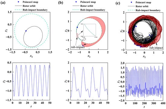
Figure 14.
Rotor orbit, Poincaré map, and time series under varying stator stiffnesses at
: (a)
, 0/1 motion; (b)
, 2/2 motion; (c)
, chaos.
5.5. Analysis of Some Typical Phenomena of the System
5.5.1. Grazing Phenomenon
Figure 15 provides a detailed description of the system during the process of approaching the verge of motion. When
, the system is in 0/1 motion. As can be seen from Figure 15a, at this time, the rotor has not collided with the stator, the rotor orbit has not crossed the collision boundary, and the Poincaré section plot is a single point. As the rotational speed increases to
, as shown in Figure 15b, the amplitude of the system vibration increases and gradually approaches the collision boundary. At this point, a grazing phenomenon occurs, but the system still exhibits 0/1 motion. When we continue to increase the rotational speed, and the system’s motion amplitude continues to increase and crosses the collision boundary, it changes from 0/1 motion to 1/1 motion. The system response is shown in Figure 15c. After that, the system enters the 2/2 motion, and the corresponding axis trajectory diagram is shown in Figure 15d. The rotor and the stator collide and impact each other twice. Subsequently, as the rotational speed increased, it can be observed from Figure 15e that the system exhibited a skidding phenomenon, transitioning from 2/2 motion to 1/2 motion. After that, the rotational speed increased to
. As can be seen from Figure 15f, the system transitioned to 2/4 motion, and its axis trajectory crossed the boundary twice. The Poincaré section diagram consisted of four independent points. From this, it can be seen that the edge case phenomenon of the system further demonstrates the diversity of the rotor system’s motion. Nodes corresponding to different rotational speeds require our greater attention.
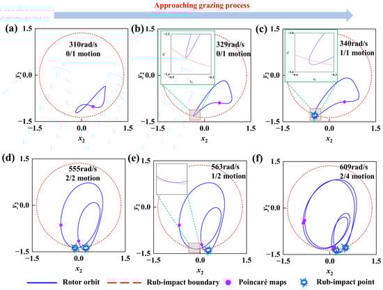
Figure 15.
The rotor orbit and Poincaré map at different rotational speeds during the grazing process.
5.5.2. The Coexistence Phenomenon of System Periodic Rubbing Vibration
A hallmark of nonlinear dynamical systems is their ability to evolve toward multiple stable steady-state solutions—coexisting attractors—from different initial conditions under an identical set of parameters. Figure 16 details the multistability observed in the rotor system over the rotational speed range
. In the figure, curves labeled
represent the system response obtained through numerical iteration with continuously increasing rotational speed, while those labeled
correspond to the response under continuously decreasing speeds. The divergence between these two paths visually demonstrates the system’s dependence on its historical trajectory, providing direct evidence for the existence of multistability. Specifically, in region A (
), the system exhibits the coexistence of period-2/2 and period-18/16 vibrations; region B (
) shows the coexistence of period-8/6 and period-2/2 vibrations; and in the broader region C (
), period-2/2 vibrations coexist with non-rubbing period-0/1 vibrations.
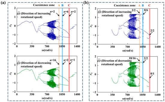
Figure 16.
The vibration response of the rotor-bearing system: (a) periodic bifurcation diagram; (b) rub-impact bifurcation diagram.
This complex coexistence stems from the coupled effects of the strongly nonlinear oil film forces and the piecewise linear rub-impact forces inherent to the system. Within specific speed intervals (e.g., region B), the nonlinear stiffness and damping characteristics provided by the oil film force interact with the instantaneous stiffness discontinuity and friction introduced during rub-impact. This interaction collectively shapes an “effective potential energy landscape” featuring multiple local minima. Consequently, which periodic motion pattern (attractor) the system ultimately stabilizes to depends on the initial conditions (e.g., initial displacement and velocity), which determine the specific local basin of attraction the system starts within. For instance, at
, as shown in Figure 17, one set of initial conditions leads the system to evolve into a complex period-8/6 rub-impact motion (corresponding to a higher-energy attractor), while another, proximate yet distinct set of initial conditions causes the system to converge to a relatively simpler period-2/2 rub-impact motion (corresponding to a lower-energy attractor). This clearly indicates the high sensitivity of the system’s nonlinear dynamic morphology to its initial state.
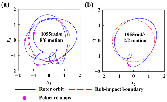
Figure 17.
The rotor orbit and Poincaré map under the coexistence phenomenon: (a) direction of increasing rotational speed; (b) direction of decreasing rotational speed.
Furthermore, the emergence of coexistence is closely linked to specific system parameter windows. It typically occurs near boundaries where the system’s dynamic behavior undergoes sharp transitions, such as in the vicinity of grazing bifurcation points or at the edges of chaotic motion regions. The coexistence intervals (A, B, C) identified in this study are situated precisely within parameter domains where the system response transitions from one stable mode to another. This observation further corroborates that coexistence phenomena are a direct manifestation of the inherent complexity of nonlinear systems near bifurcation points.
6. Discussion
This study systematically reveals the significant influence of key design and operational parameters—such as rotor–stator clearance, lubricant viscosity, and stator stiffness—on a system’s dynamic characteristics. Appropriately increasing the rotor–stator clearance or employing lubricants with a higher viscosity proves to be an effective strategy for suppressing chaotic motion and mitigating the severity of rub-impact. The rich dynamic phenomena observed, including the route to chaos via period-doubling bifurcations, grazing behavior under varying parameters, and the coexistence of attractors induced by initial conditions, provide a crucial reference for rub-impact fault diagnosis based on vibration signals.
Compared to the existing literature, the innovations of this work are threefold: (1) The introduction of the rubbing ratio concept within a coupled nonlinear oil film and rub-impact force model for a dual-disk rotor system enables the quantitative description of contact duration. Combined with the maximum rub-impact force, this offers a more comprehensive assessment of rub-impact intensity. (2) Beyond merely tracking changes in dynamic behavior, the analysis delves deeper into how critical structural parameters influence the occurrence region, frequency, and intensity of the rub-impact itself, establishing clear correlations among parameters, system response, and rub-impact severity. (3) The work explicitly demonstrates the existence of coexisting attractors within specific parameter ranges, highlighting the importance of initial conditions and nonlinear path dependence in rotor system response—an insight with significant implications for fault reproduction and diagnostic analysis.
While the lumped parameter model, based on short bearing theory under isothermal and laminar flow assumptions, successfully uncovers core dynamic mechanisms, certain limitations remain. Future work will focus on the following directions: (1) Experimental validation: Constructing a corresponding rotor-bearing test rig to validate and refine the theoretical model using measured data on vibration response, oil film pressure, and temperature. (2) Model refinement: Incorporating thermal effects and non-Newtonian properties of the lubricant film, as well as exploring more complex bearing models (e.g., tilting-pad bearings), to achieve more accurate simulations of high-speed and heavy-duty conditions. (3) Extended fault analysis: Investigating the coupled nonlinear dynamics of rub-impact interacting with other common faults such as cracks, misalignment, and seal excitation.
7. Conclusions
This paper examines the numerical solutions of the dynamic equations for a sliding bearing double-disk rotor system influenced by friction and strong nonlinear coupling, including factors like oil film force. Additionally, under laminar flow and isothermal conditions, it investigates how variations in system parameters affect the dynamic response of a rotating subsystem. The conclusions derived from this study are as follows:
The system exhibits a rich spectrum of dynamic behaviors—including single-period, multi-period, quasi-periodic, and chaotic motions—strongly modulated by structural parameters and rotational speed. Specifically, we find that rotor–stator clearance plays a decisive role in stability: small clearances promote widespread rub-impact with high intensity, whereas larger clearances simplify the motion to predominantly periodic patterns, shrink chaotic regions, and enhance overall stability.
Lubricant viscosity emerges as another key stabilizer. A high viscosity suppresses chaotic motion, reduces rub-impact severity, and favors periodic orbits. Conversely, decreasing viscosity expands chaotic and quasi-periodic regimes, increases both the prevalence and intensity of rub-impact, and systematically degrades system stability. The main reason is that high-viscosity lubricating oil can provide stronger linear damping to dissipate vibration energy.
Notably, increasing stator stiffness diversifies periodic vibration modes and enlarges chaotic windows. This is accompanied by a rise in the maximum friction force and rub-impact ratio, indicating more severe friction interactions, although the onset speed of rub-impact remains unaffected. Different initial values and paths can also lead to coexistence phenomena, which have certain influences on the dynamic response of the system.
These parametric maps provide practical guidance for mitigating rub-impact risks in rotor-bearing systems, highlighting clearance adjustment and viscosity control as effective strategies for enhancing operational stability.
Author Contributions
Conceptualization, J.L. and L.Z.; Methodology, J.L., J.W. and G.Z.; Software, J.L. and T.W.; Resources, J.L. and G.Z.; Writing—original draft, J.L.; Writing—review and editing, G.Z., J.W. and L.Z.; Supervision, L.Z., J.W. and M.L. All authors have read and agreed to the published version of the manuscript.
Funding
This work is supported by the President’s fund project of improving the research ability of young and middle-aged teachers in Guangxi universities (2024KY0806).
Data Availability Statement
Data are contained within the article.
Acknowledgments
This work was supported by the project of improving the research ability of young and middle-aged teachers in Guangxi universities, which is gratefully acknowledged.
Conflicts of Interest
The authors declare no conflicts of interest.
Abbreviations
| Nomenclature | |
| C | Bearing radial clearance (mm) |
| Ci | Damping coefficient (N·s/m) |
| f | Friction coefficient |
| FX, FY | Dimensional components of fluid film force (N) |
| PX, PY | Dimensional components of rub-impact force (N) |
| K | Shaft stiffness (N/m) |
| Kc | Stator stiffness (N/m) |
| L | Length of bearing (mm) |
| R | Bearing radius (mm) |
| μ | Lubricating oil viscosity (Pa·s) |
| σ | Somerfield revision number |
| g | Acceleration of gravity (m/s2) |
| M1/M4 | Mass of bearings (kg) |
| M2/M3 | Mass of disks (kg) |
| O1/O4 | Geometric center of bearing |
| O2/O3 | Geometric center of disks |
| X, Y | Vibration displacement in the X and Y directions (m) |
| x, y | Dimensionless vibration displacements of the X and Y directions |
| δj | Mass eccentricity of the j-th disk (mm) |
| δr | Radial displacement of the rotor (mm) |
| ρr | Clearance between rotor and stator (mm) |
| p/n | A method for representing a motion state (number of collisions/number of cycles) |
| Pmax | Dimensionless maximum friction force |
| DC | Friction duty cycle |
References
- Shaw, A.D.; Champneys, A.R.; Friswell, M.I. Asynchronous partial contact motion due to internal resonance in multiple de-gree-of-freedom rotor dynamics. Proc. R. Soc. A Math. Phys. Eng. Sci. 2016, 472, 20160303. [Google Scholar]
- Chang-Jian, C.W.; Chen, C.K. Bifurcation and chaos analysis of a flexible rotor supported by turbulent long journal bearings. Chaos Solitons Fractals 2007, 34, 1160–1179. [Google Scholar] [CrossRef]
- Xiang, L.; Gao, X.; Hu, A. Nonlinear dynamics of an asymmetric rotor-bearing system with coupling faults of crack and rub-impact under oil-film forces. Nonlinear Dyn. 2016, 86, 1057–1067. [Google Scholar] [CrossRef]
- Vlajic, N.; Champneys, A.R.; Balachandran, B. Nonlinear dynamics of a Jeffcott rotor with torsional deformations and rotor-stator contact. Int. J. Non-Linear Mech. 2017, 92, 102–110. [Google Scholar] [CrossRef]
- Ma, H.; Li, H.; Zhao, X.; Niu, H.; Wen, B. Effects of eccentric phase difference between two discs on oil-film instability in a rotor–bearing system. Mech. Syst. Signal Process. 2013, 41, 526–545. [Google Scholar] [CrossRef]
- Phadatare, H.P.; Pratiher, B. Large deflection model for rub-impact analysis in high-speed rotor-bearing system with mass unbalance. Int. J. Non-Linear Mech. 2021, 132, 103702. [Google Scholar] [CrossRef]
- Zhou, W.J.; Wei, X.S.; Wei, X.Z.; Wang, L.Q. Numerical analysis of a nonlinear double disc rotor-seal system. J. Zhejiang Univ.—Sci. A Appl. Phys. Eng. 2014, 15, 39–52. [Google Scholar] [CrossRef]
- Zhang, Y.; Wang, W.; Wei, D.; Wang, G.; Xu, J.; Liu, K. Unbalance Response and Stability Analysis of a High-speed Turbocharger Bearing-Rotor System. Tribology 2021, 41, 620–631. [Google Scholar]
- Xiang, L.; Hu, A.; Hou, L.; Xiong, Y.; Xing, J. Nonlinear coupled dynamics of an asymmetric double-disc rotor-bearing system under rub-impact and oil-film forces. Appl. Math. Model. 2016, 40, 4505–4523. [Google Scholar] [CrossRef]
- Hu, A.; Hou, L.; Xiang, L. Dynamic simulation and experimental study of an asymmetric double-disk rotor-bearing system with rub-impact and oil-film instability. Nonlinear Dyn. 2016, 84, 641–659. [Google Scholar] [CrossRef]
- Zeng, X. Nonlinear dynamic response analysis of dual-disk rub-impact rotor-rolling bearing system. Mod. Manuf. Eng. 2020, 479, 141–146. [Google Scholar]
- Liu, J.; Zhang, L.; Yin, F.; Qin, Z. Nonlinear response analysis of double disk rubbing rotor—oil film bearing system. J. Mech. Strength 2020, 42, 1310–1315. [Google Scholar]
- Qin, Z.-F.; Shi, H.-R.; Shi, Y.-Q. Dynamic behavior of a double-disc rotor system considering oil film force-impact force coupling. J. Lanzhou Jiaotong Univ. 2020, 39, 95–100. [Google Scholar]
- Zhang, L.-Y.; Li, L.; He, X.-Y. Influence of Rotary Disc eccentricity on Dynamic Response of Misaligned and anti-friction Rotor. Mach. Tools Hydraul. 2024, 52, 117–123. [Google Scholar]
- Yin, F.; Wang, X.; Wang, X. Rub-impact vibration characteristics of double-disc rotor system with magnetic bearings. J. Railw. Sci. Eng. 2024, 21, 299–313. [Google Scholar]
- Cao, L.; Li, D.; Yu, M.; Si, H.; Zhang, Z. Influence of Seal Structure on the Motion Characteristics and Stability of a Steam Turbine Rotor. Machines 2024, 12, 670. [Google Scholar] [CrossRef]
- Gao, J.; Qin, W.; Liang, X.; Yang, Y.-F.; Wang, Z. Stochastic bifurcation and chaos analysis of a rub-impact rotor-bearing system. J. Vib. Shock. 2013, 32, 161–164. [Google Scholar]
- Zhou, Z.; Huang, J. Study of RCS characteristics of Tilt-rotor aircraft based on dynamic calculation approach. Chin. J. Aeronaut. 2022, 35, 426–437. [Google Scholar] [CrossRef]
- Huang, J.; Zhou, Z. V-shaped deformation quadrotor radar cross-section analysis. Proc. Inst. Mech. Eng. 2025, 239, 1276–1290. [Google Scholar]
- Jin, H.; Wang, Y.; Wang, X.; Zhang, X.; Wang, K.; Li, G. Nonlinear vibrations of a dual-rotor system with aerodynamic excitation. Int. J. Mech. Sci. 2025, 305, 110738. [Google Scholar] [CrossRef]
- Zhang, X.; Yang, Y.; Deng, W.; Zhao, S.; Zhu, Q.; Ma, H.; Han, Q.; Qin, Z.; Liu, W. Vibration energy analysis of rub-impact rotor system: Nonlinear fault-induced energy response and transfer state. Mech. Syst. Signal Process. 2025, 236, 113035. [Google Scholar] [CrossRef]
- Liu, Y.; Yan, C.; Shi, J.; Kang, J.; Liu, B.; Wu, L. Nonlinear dynamic analysis of supporting bearing in rotor-bearing system considering vibration interaction. Nonlinear Dyn. 2025, 113, 22435–22458. [Google Scholar] [CrossRef]
- Fasihi, A.; Shahgholi, M.; Kudra, G.; GhandchiTehrani, M.; Awrejcewicz, J. The influence of rotor-stator contact on the nonlinear vibration of an asymmetrical rotor. Nonlinear Dyn. 2025, 113, 27435–27457. [Google Scholar] [CrossRef]
- Zhang, J.; Xie, Z.; Zhang, K.; Deng, Z.; Wu, D.; Su, Z.; Huang, X.; Song, M.; Cao, Y.; Sui, J. Nonlinear Dynamic Analysis of Gas Bearing-Rotor System by the Hybrid Method Which Combines Finite Difference Method and Differential Transform Method. Lubricants 2022, 10, 302. [Google Scholar] [CrossRef]
- Capone, G. Descrizione analitica del campo di forze fluidodinamico nei cuscinetti cilindrici lubrificati. Energ. Elettr. 1991, 68, 105–110. [Google Scholar]
- Adiletta, G.; Guido, A.R.; Rossi, C. Chaotic motions of a rigid rotor in short journal bearings. Nonlinear Dyn. 1996, 10, 251–269. [Google Scholar] [CrossRef]
- Sun, W.; Yan, Z.; Tan, T.; Zhao, D.; Luo, X. Nonlinear characterization of the rotor-bearing system with the oil-film and unbalance forces considering the effect of the oil-film temperature. Nonlinear Dyn. 2018, 92, 1119–1145. [Google Scholar] [CrossRef]
- Luo, G.W. Hopf-flip bifurcations of vibratory systems with im-pacts. Nonlinear Anal. Real World Appl. 2006, 7, 1029–1041. [Google Scholar] [CrossRef]
Disclaimer/Publisher’s Note: The statements, opinions and data contained in all publications are solely those of the individual author(s) and contributor(s) and not of MDPI and/or the editor(s). MDPI and/or the editor(s) disclaim responsibility for any injury to people or property resulting from any ideas, methods, instructions or products referred to in the content. |
© 2026 by the authors. Licensee MDPI, Basel, Switzerland. This article is an open access article distributed under the terms and conditions of the Creative Commons Attribution (CC BY) license.