Abstract
Due to low thermal conductivity and high specific strength, nickel-based superalloys are prone to service performance degradation caused by thermal damage during traditional high-efficiency grinding processes. Although the heat pipe grinding wheel with minimum quantity lubrication (HPGW-MQL) technology can reduce the probability of thermal damage to a certain extent, further breakthroughs are still needed. Therefore, this study proposes a new integrated process of ultrasonic vibration-assisted grinding by heat pipe grinding wheel with minimum quantity lubrication (UVAG-HPGW-MQL), aiming to balance the requirements of green grinding and the optimization of grinding performance for nickel-based superalloys. However, the mechanism of action of ultrasonic vibration on the cooling and lubrication performance of the proposed process remains unclear. Given that, comparative experiments between UVAG-HPGW-MQL and HPGW-MQL were conducted, focusing on exploring the influence of ultrasonic vibration on their cooling and lubrication performance. The experimental results, obtained when the grinding speed, workpiece feed rate, and grinding depth were set at 15–35 m/s, 40–120 mm/min, and 0.05–0.25 mm, respectively, indicate that, compared with HPGW-MQL, ultrasonic vibration causes periodic “contact-separation” between grains and workpiece. This dynamic process shortens the contact length between grains and workpiece, leading to maximum reductions of 43.85%, 22.15%, 34.16%, and 30.77% in grinding force, grinding force ratio, grinding temperature, and specific grinding energy, respectively. On the other hand, the ultrasonic cavitation effect causes atomization of the lubricating oil film adsorbed on the workpiece surface, leading to a decrease in lubrication performance and resulting in a maximum increase of 27.27% in the friction coefficient. This study provides new theoretical support and technical approaches for the green grinding of nickel-based superalloys.
1. Introduction
Owing to their excellent comprehensive properties such as high strength and toughness, oxidation resistance, and thermal fatigue resistance, nickel-based superalloys have become one of the indispensable core materials for key hot-end components of high-end equipment such as aero-engine turbine blades and combustion chambers [1,2,3]. As the final process for component forming, grinding quality directly affects the service life and reliability of components [4]. However, while nickel-based superalloys possess the aforementioned excellent properties, their material characteristics such as low thermal conductivity and high specific strength lead to the easy generation and accumulation of a large amount of heat in grinding zone during process, which tends to cause irreversible thermal damages such as grinding burn and thermal crack initiation, seriously reducing surface integrity and dimensional accuracy [5,6,7,8].
In order to reduce grinding temperature and conform to the development trend of modern green grinding, the rotating heat pipe cooling technology is applied to the grinding wheel metal matrix [9,10]. The cyclic phase change in working fluid can significantly improve grinding wheel heat transfer performance, thereby enhancing heat transfer in the grinding zone [11,12]. A developed heat pipe grinding wheel (HPGW) can effectively conduct grinding heat without using cooling fluid and has now become one of the effective solutions for cooling the grinding zone [13,14,15,16]. However, grinding heat is essentially generated from elastic deformation, plastic deformation, and frictional work between grains and the workpiece. HPGW does not change the interaction mode between grains and the workpiece; therefore, it can only efficiently conduct the generated grinding heat rather than interfering with the generation process of grinding heat from the source.
To reduce the generation of grinding heat, researchers have developed a new green minimum quantity lubrication (MQL) cooling technology [17,18,19,20]. This technology mixes and atomizes an extremely small amount of cooling fluid (10–100 mL/h) with high-pressure air to form micron-sized droplets (5–50 μm) that are sprayed onto the machining interface, enabling the formation of a stable lubricating oil film in the grain-workpiece contact zone [21,22]. Theoretical studies have shown that the core friction-reducing mechanism of MQL at the grinding interface lies in its excellent lubrication performance brought by the lubricating oil film, which can effectively reduce the friction coefficient [23,24]. Zhang et al. [25] conducted a comparative study on the machining of Ti-6Al-4V titanium alloy and found that, compared with the dry grinding process, the adoption of MQL technology can reduce the friction coefficient, thereby decreasing frictional heat generation. Zhao et al. [26] revealed in the machining of Fiber-reinforced resin matrix composites (FRP) that the excellent lubrication performance of MQL can significantly reduce the friction force and grinding force ratio during grinding, and reduce fiber wear. Li et al. [27] further confirmed that the lubricating oil film generated under MQL can not only effectively inhibit the temperature rise in the grinding zone but also greatly improve workpiece surface quality. The above studies indicate that MQL technology has significant advantages in reducing friction and lubrication, temperature control, and improving surface integrity.
Therefore, HPGW-MQL, which combines HPGW and MQL, has a dual advantage: on the one hand, it relies on the lubrication and cooling of MQL to reduce grinding heat generation from the source; on the other hand, it relies on the excellent heat transfer performance of HPGW to effectively conduct the generated grinding heat. However, although MQL has shown good lubrication and cooling effects in the field of precision grinding with small cutting depths, HPGW is generally applicable to large cutting depth application scenarios under creep feed deep grinding processes. In such scenarios, the contact length of the grinding zone is long and relatively closed, and the instantaneous heat generation density is high. Therefore, relying solely on the oil mist lubrication and cooling of MQL is prone to local heat accumulation in the grinding zone due to problems such as insufficient oil mist penetration depth.
As a special energy field-assisted machining technology, ultrasonic vibration promotes periodic “contact-separation” between grains and workpiece by exciting high-frequency micro-amplitude vibration between the tool and the workpiece, and it has now become one of the key technologies to solve the grinding bottlenecks of difficult-to-machine materials (superalloys, titanium alloys, ceramics, composites, etc.) [28,29,30,31,32,33,34,35]. Wu et al. [36] studied the influence of grinding parameters on grinding force and surface roughness of Cf/SiC composites in traditional grinding (CG) and ultrasonic vibration-assisted grinding (UVAG). The study found that, compared with CG, UVAG is a more effective and accurate material processing method, which reduces grinding force and improves workpiece surface machining quality. Huang et al. [37] compared the grinding temperatures of hardened steel under CG and UVAG. The experimental results showed that ultrasonic vibration improved the heat transfer capacity of cooling fluid in the grinding zone, reducing grinding temperature by 19.01%. Zhao et al. [38] established thermal models and finite element simulation models of γ-TiAl material under two working conditions, high-efficiency deep grinding and ultrasonic vibration-assisted high-efficiency deep grinding, and conducted comparative grinding experiments. The experimental results showed that the introduction of ultrasonic vibration effectively inhibited grinding burn, and the prediction error with the simulation model was within 15%. Tawakoli et al. [39] applied ultrasonic vibration to the dry grinding experiment of 100Cr6 steel and found that the intermittent grinding method reduced contact length between the grinding wheel and workpiece, thereby reducing the grinding force, friction effect, and plastic deformation zone and further reducing grinding temperature. The above studies indicate that UVAG can also reduce grinding heat generation from the source due to its unique machining method.
To further reduce grinding heat generation, researchers have attempted to combine UVAG and MQL [40,41]. Molaie et al. [42] observed that UVAG and MQL have complementary mechanisms of action, and their combined use can significantly reduce grinding force and improve surface roughness. Das et al. [43,44] introduced ultrasonic vibration into MQL and found that the periodic separation characteristic between grains and workpiece enables the lubricating medium to effectively penetrate into the grinding zone, thereby enhancing lubrication performance. Rabiei et al. [45] compared the friction coefficient and grinding temperature under three grinding conditions (MQL, UVAG, and UVAG-MQL) through experiments and found that the values were the lowest under the UVAG-MQL composite condition. Gao et al. [46,47] established a grinding force model for UVAG-MQL grinding of carbon fiber reinforced polymer (CFRP) and verified that the model has acceptable estimation errors. In addition, experiments showed that ultrasonic vibration helps to reduce the stable aspect ratio of MQL oil mist droplets and increase their spreading speed, improving the cooling and lubrication effects. Collectively, these studies confirm that the integration of UVAG and MQL achieves synergistic optimization of grinding performance—ultrasonic vibration enhances the accessibility and effectiveness of MQL, while MQL supplements UVAG’s heat reduction effect, jointly reducing key indicators such as grinding force, temperature, and friction coefficient, and improving surface quality.
In summary, to further improve the grinding performance of nickel-based superalloys by heat pipe grinding wheel with minimum quantity lubrication, this study proposes and deeply explores a new process of ultrasonic vibration-assisted grinding by heat pipe grinding wheel with minimum quantity lubrication (UVAG-HPGW-MQL). Through comparative grinding experiments, the variation laws of grinding force, grinding force ratio, grinding temperature, specific grinding energy, and lubrication performance under two grinding conditions (UVAG-HPGW-MQL and HPGW-MQL) will be systematically analyzed. This study innovatively integrates UVAG, HPGW, and MQL into a unified process for Inconel 718 grinding, revealing the dual effect of ultrasonic vibration on cooling and lubrication balance, as well as the advantages and prospects of this process in green grinding of nickel-based high-temperature alloys.
2. Materials and Methods
2.1. Experimental Equipment
Figure 1 shows the setup of grinding experimental platform. An ultrasonic vibration-assisted grinding device for workpieces was installed on the workbench of a Profimat MT-408 surface grinder (Blohm Jung Co., Ltd., Hamburg, Germany), with the following main technical parameters: maximum spindle power of 45 kW; maximum grinding wheel speed of 8000 r/min; maximum allowable grinding wheel diameter of 400 mm. The workpiece material was Inconel 718, a typical nickel-based superalloy used in aero-engines, with dimensions (length × width × height) of 30 mm × 12 mm × 10 mm. Table 1 lists the chemical composition of Inconel 718. The grinding tool used was a heat pipe grinding wheel modified from a single-layer electroplated CBN grinding wheel matrix, with dimensions (outer diameter × thickness × inner diameter) of Φ350 mm × 35 mm × Φ127 mm, the grains size of 80/100#, and 100 mL of anhydrous ethanol was injected into the annular tube cavity as the cyclic phase change working fluid. The MQL system adopted an external oil supply device (model: MIDORI FS, Bluebe Environmental Protection Technology Co., Ltd., Shanghai, China), using dual nozzles to spray lubricating oil, with a flow rate of 50 mL/h per nozzle and an input air pressure of 0.6 MPa. The sprayed lubricating oil was prepared by mixing soybean oil and castor oil at a ratio of 1:1, with 0.2% (by volume) of antioxidant vitamin E oil added to prevent the failure of the mixed lubricating oil [48]. According to the application position of ultrasonic vibration, ultrasonic vibration-assisted grinding can be divided into tool ultrasonic vibration and workpiece ultrasonic vibration. This study adopted workpiece ultrasonic vibration, whose working principle is as follows: the power supply outputs a high-frequency electrical signal to the transducer; the piezoelectric ceramics in the transducer convert the electrical signal into mechanical vibration using the piezoelectric effect; the amplitude is amplified by the amplitude transformer and transmitted to the workpiece fixedly installed on the porous platform. The experiment controlled the addition of ultrasonic vibration by turning the power switch on or off, with a resonant frequency of 19.4 kHz, a fixed amplitude of 3 μm, and the vibration direction along the feed direction (tangential). The creep feed deep grinding process and the up-grinding mode (opposite directions of grinding wheel rotation and workpiece feed) were adopted. Each set of grinding parameters was repeated 3 times to ensure the authenticity and reliability of the data. The specific parameters and conditions of grinding experiment are shown in Table 2.
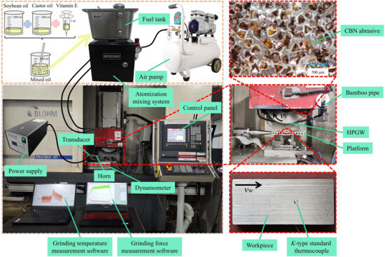
Figure 1.
Grinding experimental setup.

Table 1.
Chemical composition of Inconel 718 [49].
Table 2.
Specific parameters and conditions of the grinding experiment.
2.2. Testing Methods
To explore the grinding performance of Inconel 718 under two working conditions (UVAG-HPGW-MQL and HPGW-MQL), a Kistler 9253B dynamometer (Kistler Group, Winterthur, Switzerland) was used to collect the grinding force signals in the horizontal and vertical directions during processing. After amplification by a Kistler 5080A charge amplifier (Kistler Group, Winterthur, Switzerland), the collected grinding force signals were processed using DynoWare 3.3.2.0 software. Grinding temperature was measured using a K-type standard thermocouple combined with an NI USB-6225 data acquisition card, and temperature signals were processed using LabVIEW 2020 software. The measurement position of grinding temperature is shown in Figure 1. A Sensofar S Neox 3D confocal microscope (Sensofar Group, Terrassa, Spain) was used to observe workpiece surface morphology. In addition, an HRX-01 3D digital microscope (Hirox Co., Ltd., Tokyo, Japan) was used to observe and count the number of effective cutting points.
3. Results and Discussion
3.1. Grinding Force
Grinding force, including the normal force per unit width (Fn′) and tangential force per unit width (Ft′), is one of the important parameters for evaluating material grinding performance and the difficulty of material removal, and its magnitude significantly affects grinding temperature, specific grinding energy, and workpiece surface quality. The ratio of the normal force per unit width to the tangential force per unit width (Fn′/Ft′) is called the grinding force ratio, which can reflect the sharpness of the grinding wheel; a smaller value indicates higher sharpness of the grinding wheel. Therefore, to analyze the grinding performance of Inconel 718, grinding forces and grinding force ratios under two working conditions (UVAG-HPGW-MQL and HPGW-MQL) were compared.
The maximum undeformed chip thickness (agmax) is a key parameter reflecting the variation in grinding force, and its calculation formula is as follows:
where Nd refers to the dynamic average number of effective abrasive grains per unit area on the grinding wheel surface, which is 6 mm−2 after observation using an HRX-01 3D digital microscope; C is a constant related to the sharpness of grains, taking a value of 6.89; and ds represents the grinding wheel diameter.
Figure 2a shows that, as grinding speed (vs) increases, the variation trends of grinding forces under the two working conditions are basically consistent, but the grinding force under UVAG-HPGW-MQL is always lower than that under HPGW-MQL. When vs varies between 15 and 35 m/s, Fn′ and Ft′ under HPGW-MQL fluctuate between 3.36 and 3.66 N/mm and 0.83–0.91 N/mm, respectively, while those under UVAG-HPGW-MQL fluctuate between 2.31 and 2.75 N/mm and 0.62–0.8 N/mm, with maximum reductions of 31.86% and 27.91%, respectively. Figure 2b,c show that both Fn′ and Ft′ exhibit an increasing trend as the workpiece feed rate (vw) and grinding depth (ap) increase, primarily due to the relative increase in agmax. According to Equation (1), when vw increases from 40 mm/min to 120 mm/min, agmax increases from 0.21 μm to 0.36 μm; when ap increases from 0.05 mm to 0.25 mm, agmax increases from 0.25 μm to 0.37 μm. In addition, except when ap reaches 0.25 mm, where the grinding forces under the two working conditions are relatively close, the grinding force under UVAG-HPGW-MQL is still lower than that under HPGW-MQL under other grinding parameters. Among them, when ap is 0.05 mm, the force reduction effect of ultrasonic vibration is the best, with the reductions of Fn′ and Ft′ reaching 43.85% and 30.77%, respectively. It can be found that the force reduction effect of ultrasonic vibration is more obvious when ap is small, and the effect gradually weakens with the increase in ap. This is mainly because a larger ap requires the grains to remove more materials during the “contact” phase of the ultrasonic vibration cycle, resulting in a significant extension of the effective contact time between grains and workpiece. When ap exceeds a certain critical value, the “separation” effect of ultrasonic vibration basically fails, and the contact state between grains and workpiece approaches that of HPGW-MQL; therefore, the difference in grinding force between the two working conditions gradually decreases until it disappears.
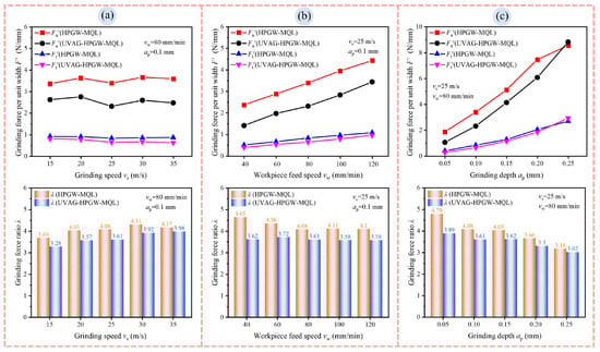
Figure 2.
Influence of (a) grinding speed, (b) workpiece feed speed, (c) grinding depth on grinding force and grinding force ratio.
It can also be seen from Figure 2 that, under all grinding parameters, compared with HPGW-MQL, UVAG-HPGW-MQL can obtain a lower and more stable grinding force ratio, which also indicates that the grinding wheel under this working condition has higher sharpness. Among them, the grinding force ratio under UVAG-HPGW-MQL fluctuates between 3.02 and 3.98, while that under HPGW-MQL fluctuates between 3.18 and 4.79, with a maximum reduction of 22.15%. This is mainly due to the periodic “contact-separation” dynamic process caused by ultrasonic vibration, which reduces the accumulation and adhesion of adhesive Inconel 718 chips at grain edges, avoiding the loss of grinding ability of grains.
3.2. Grinding Temperature
An increase in grinding temperature can have negative impacts on surface integrity, dimensional accuracy of processed workpiece, and the wear state of the grinding wheel; therefore, it is necessary to control grinding temperature in a timely and effective manner. In this study, the original grinding temperature signals (after low-pass filtering) measured by K-type standard thermocouple were taken as the research object, and the temperature rise characteristics of the grinding zone of Inconel 718 under two working conditions (UVAG-HPGW-MQL and HPGW-MQL) were compared.
Figure 3 shows the influence of grinding parameters on grinding temperature. Different from the smooth grinding temperature signal curve measured under HPGW-MQL, the grinding temperature signal under UVAG-HPGW-MQL shows oscillation due to the addition of ultrasonic vibration. In addition, with the increase of vs, vw, and ap, the grinding temperatures under both working conditions show an increasing trend; however, compared with HPGW-MQL, the grinding temperature under UVAG-HPGW-MQL remains lower. This is mainly because the addition of ultrasonic vibration changes the generation and transfer mechanism of heat in the grinding zone, which acts jointly from two aspects: “reducing heat source generation” and “strengthening heat dissipation”. “Reducing heat source generation” is mainly reflected in the fact that the periodic “contact-separation” working mode can avoid local overheating of grains caused by continuous high-pressure friction, reducing the total amount of frictional heat generation in the grinding zone from the source and directly reducing grinding temperature accumulation. “Strengthening heat dissipation” is mainly reflected in the fact that the dynamic gap between grains and workpiece generated by ultrasonic vibration can break the “closed” environment of the traditional grinding zone; when the gap expands, more cooling medium can be sucked in, enhancing the convective heat transfer on the surfaces of grains and workpiece.
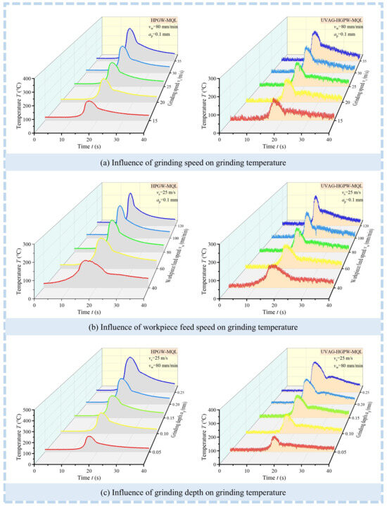
Figure 3.
Influence of grinding parameters on grinding temperature.
Figure 3a shows that, when vs increases from 15 m/s to 35 m/s, the grinding temperature under HPGW-MQL increases from 150.71 °C to 332.01 °C, while that under UVAG-HPGW-MQL increases from 114.49 °C to 218.61 °C, with a reduction range of 24.03–34.16%. Figure 3b shows that the grinding temperature under UVAG-HPGW-MQL increases gently when vw is in the range of 40–100 mm/min; when vw increases from 100 mm/min to 120 mm/min, the grinding temperature increases rapidly, from 173.85 °C to 224.68 °C. At the same time, the grinding temperature under HPGW-MQL increases rapidly when vw increases from 40 mm/min to 60 mm/min, from 156.91 °C to 189.79 °C. The reason for the increase in grinding temperature is that, when vw increases from 40 mm/min to 120 mm/min, the material removal rate increases from 0.07 mm3/(mm·s) to 0.2 mm3/(mm·s). Figure 3c shows that, compared with vs and vw, the increase in ap has a greater influence on grinding temperature. On the one hand, it is due to the 5-fold increase in the material removal rate (from 0.07 mm3/(mm·s) to 0.33 mm3/(mm·s)); on the other hand, it is because a larger ap increases agmax, leading to an increase in grinding force and thus more grinding heat generation. The grinding temperature under HPGW-MQL increases from 148.88 °C to 400.78 °C, while that under UVAG-HPGW-MQL increases from 112.33 °C to 302.81 °C, with a maximum reduction of 29.2%. In addition, under both working conditions, when the grinding depth increases from 0.2 mm to 0.25 mm, grinding temperature rises most sharply: under HPGW-MQL, it increases from 307.84 °C to 400.78 °C; under UVAG-HPGW-MQL, it increases from 235.41 °C to 302.81 °C, with increases of 92.94 °C and 67.4 °C, respectively.
3.3. Specific Grinding Energy
Specific grinding energy (es) is defined as the energy consumed to remove a unit volume of workpiece material, which is an important reference index for measuring energy consumption and grinding efficiency during the grinding process. Equation (2) is used to calculate es:
where Qw represents the material removal volume, which can be obtained by the product of vw and ap.
Figure 4 shows the influence of grinding parameters on specific grinding energy. It can be seen that the specific grinding energy under both working conditions increases with the increase in vs and ap (Figure 4a,c), and decreases with the increase in vw; under UVAG-HPGW-MQL, it tends to be stable when vw is 80–120 mm/min (Figure 4b). Compared with HPGW-MQL, the specific grinding energy under UVAG-HPGW-MQL is slightly higher only when the grinding parameters are vs = 35 m/s, vw = 40 mm/min, and ap = 0.25 mm; under other grinding parameters, it is at a lower level. This variation law is consistent with the variation law of grinding force mentioned above. This indicates that, when using UVAG-HPGW-MQL, Inconel 718 has better grinding performance, less energy is consumed to remove a unit volume of workpiece material, and the material is easier to remove. In addition, it can be seen from Figure 4 that the maximum reductions in specific grinding energy occur when vs = 35 m/s, vw = 40 mm/min, and ap = 0.05 mm, reaching 27.91%, 23.53%, and 30.77%, respectively.
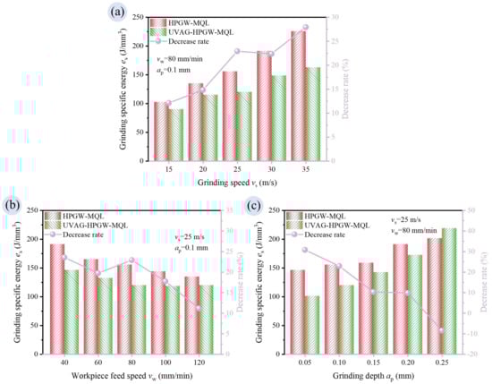
Figure 4.
Influence of (a) grinding speed, (b) workpiece feed speed, (c) grinding depth on specific grinding energy.
4. Lubrication Performance Analysis
4.1. Friction Coefficient
The core function of lubrication performance is to reduce the interaction intensity of the friction interface, and the friction coefficient (μ) is a quantitative index for measuring the resistance of the friction interface, showing a significant negative correlation with lubrication performance. During the grinding process of metal materials, the grinding forces (Fn and Ft) are mainly composed of two components: the chip formation component (Fnc and Ftc) and the friction component (Fnf and Ftf), as shown in Figure 5. Therefore, the calculation Equation (3) of grinding force is as follows:
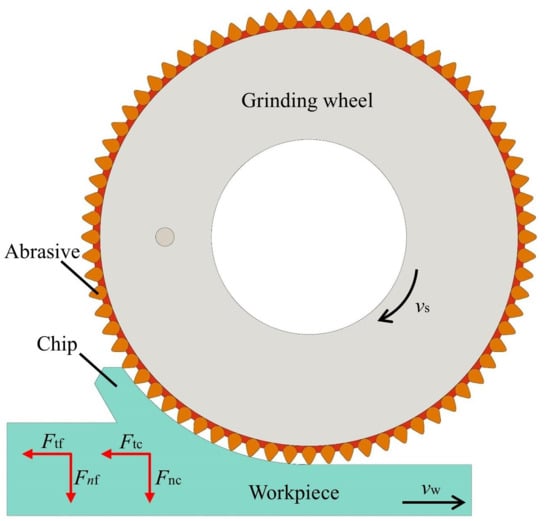
Figure 5.
Force state of the grinding wheel during the grinding process.
According to the grinding force model proposed by T. W. Hwang [50], the friction components (Fnf and Ftf) are linearly related to the contact area (A), and this relationship is determined by the friction coefficient (μ) between workpiece and wear surface and constant pressure (P). Based on this, the calculation formula of grinding force can be further expressed as follows:
Thus, the calculation formula of μ is obtained as follows:
Since the grinding condition is minimum quantity lubrication grinding, the grinding process is dominated by “friction”, and the contribution of chip formation can be ignored. Therefore, the calculation formula of μ can be expressed as follows:
Figure 6 shows the influence of grinding parameters on the friction coefficient. It can be seen that, under all grinding parameters, the friction coefficient under UVAG-HPGW-MQL is larger than that under HPGW-MQL. The friction coefficient under UVAG-HPGW-MQL ranges from 0.25 to 0.33, while that under HPGW-MQL ranges from 0.21 to 0.31, with a maximum increase of 27.27%. This is mainly because the high-frequency vibration caused by ultrasound will produce a cavitation effect, leading to the generation, growth, and collapse of micro-bubbles inside the lubricating oil film adsorbed on the workpiece surface, as shown in Figure 7. This intense physical process may cause local rupture, thinning, or uneven distribution of the lubricating film, increasing the direct contact area between the abrasive grains and the workpiece surface, thereby increasing friction and leading to an increase in the friction coefficient.
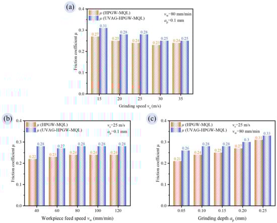
Figure 6.
Influence of (a) grinding speed, (b) workpiece feed speed, (c) grinding depth on friction coefficient.
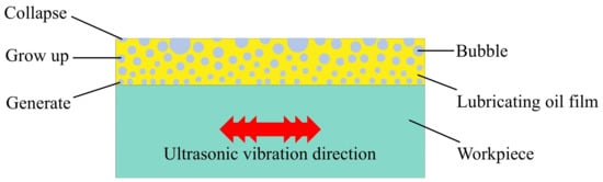
Figure 7.
Schematic diagram of the growth process of bubbles in lubricating oil film.
4.2. Workpiece Surface Roughness
Figure 8 shows the surface morphology and surface roughness of processed workpiece observed using a Sensofar S Neox 3D confocal microscope under two working conditions when vs = 25 m/s, vw = 80 mm/min, and ap = 0.1 mm and 0.25 mm, respectively. It can be found that, when ap = 0.1 mm, workpiece surface roughness (Ra) measured under HPGW-MQL and UVAG-HPGW-MQL is 0.260 μm and 0.296 μm, respectively; the Ra value increases by 14.85% after adding ultrasonic vibration. When ap = 0.25 mm, Ra measured under HPGW-MQL and UVAG-HPGW-MQL is 0.297 μm and 0.310 μm, respectively; the Ra value increases by 4.19% after adding ultrasonic vibration. From the above analysis of the friction coefficient, it is known that the high-frequency vibration caused by ultrasound will damage the lubricating oil film adsorbed on the workpiece surface by MQL, weakening the lubrication effect and increasing the friction coefficient, which also corresponds to the final deterioration of the workpiece surface quality.
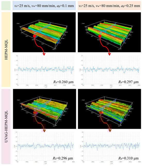
Figure 8.
Surface morphology and surface roughness of the processed workpiece.
5. Conclusions
In this study, comparative grinding experiments were conducted on the nickel-based superalloy Inconel 718 under two grinding conditions (HPGW-MQL and UVAG-HPGW-MQL). Influences of grinding parameters (i.e., grinding speed vs, workpiece feed speed vw, and grinding depth ap) on grinding force, grinding force ratio, grinding temperature, specific grinding energy, friction coefficient, and workpiece surface roughness were studied. The main conclusions are as follows:
- When grinding the nickel-based superalloy Inconel 718, compared with HPGW-MQL, UVAG-HPGW-MQL realizes intermittent grinding with periodic “contact-separation” between grains and workpiece by adding tangential ultrasonic vibration to workpiece. This dynamic process shortens the contact length between grains and workpiece, leading to maximum reductions of 43.85%, 30.77%, 22.15%, 34.16%, and 30.77% in normal force per unit width, tangential force per unit width, grinding force ratio, grinding temperature, and specific grinding energy, respectively, effectively reducing energy consumption and grinding heat accumulation during grinding process.
- The intermittent cutting behavior caused by ultrasonic vibration can reduce grinding heat generation from the source; however, the cavitation effect generated by ultrasonic vibration atomizes the lubricating oil film adsorbed on the workpiece surface, resulting in a maximum increase of 27.27% in the friction coefficient and deteriorating the surface quality of processed workpiece and ultimately increasing the workpiece surface roughness value by 4.19%.
- Considering comprehensively in UVAG-HPGW-MQL, UVAG and MQL reduce grinding heat generation from the source, and HPGW further effectively conducts the generated grinding heat. The three work synergistically to control grinding temperature and reduce the probability of thermal damage. Although the friction coefficient increases compared with HPGW-MQL, the range is not large. Therefore, UVAG-HPGW-MQL has better grinding performance in the processing of Inconel 718, which is more in line with the requirements of green grinding processing.
Author Contributions
Conceptualization, S.W. and N.Q.; methodology, S.W., Y.X. and N.Q.; validation, S.W., B.P. and Y.X.; formal analysis, B.P.; investigation, N.Q. and S.P.; resources, W.D. and Y.F.; data curation, S.W.; writing—original draft preparation, S.W., Y.X. and B.P.; writing—review and editing, N.Q., S.P., W.D. and Y.F.; visualization, N.Q.; supervision, N.Q.; project administration, W.D. and Y.F.; funding acquisition, N.Q., W.D. and Y.F. All authors have read and agreed to the published version of the manuscript.
Funding
The authors gratefully acknowledge the support of the Natural Science Foundation of Jiangsu Province (No. BK20242040), the National Natural Science Foundation of China (Grant No. 52205476), Major Program of State Key Laboratory for High Performance Tools (Grant No. GXNGJSKL-2025-08), the Fundamental Research Funds for the Central Universities (Grant No. NG2024008), and the Fund of Jiangsu Key Laboratory of Precision and Micro-Manufacturing Technology (Grant No. 1005-ZAA20003-14).
Data Availability Statement
The original contributions presented in this study are included in this article. Further inquiries can be directed to the corresponding author.
Conflicts of Interest
Author Shuai Wang was employed by the company Zhengzhou Research Institute for Abrasives & Grinding Co., Ltd. and Author Bo Pan was employed by the company Aero-Engine Corporation of China. The remaining authors declare that the research was conducted in the absence of any commercial or financial relationships that could be construed as a potential conflict of interest.
References
- Jiao, Y.; Qi, Q.; Zhu, X.; Gong, Y.; Gao, Y.; Chen, H.; Chen, F.; Wang, X. Coupled mechanisms of grain refinement through subgrain formation and lattice rotation during recrystallization of GH4169 alloy. J. Alloys Compd. 2025, 1030, 180751. [Google Scholar] [CrossRef]
- Xu, N.; Kang, R.; Zhang, B.; Zhang, Y.; Wang, C.; Bao, Y.; Dong, Z. Improving fatigue properties of normal direction ultrasonic vibration assisted face grinding Inconel 718 by regulating machined surface integrity. Int. J. Extreme Manuf. 2024, 6, 035101. [Google Scholar] [CrossRef]
- Uslu, G.; Korkmaz, M.E.; Elkilani, R.H.R.; Gupta, M.K.; Vashishtha, G. Investigation of tribological properties of Inconel 601 under environmentally friendly MQL and nano-fluid MQL with pack boronizing. Lubricants 2024, 12, 353. [Google Scholar] [CrossRef]
- Qin, B.; Liu, H.; Cheng, J.; Tian, J.; Sun, J.; Chen, M. Study on wear mechanism of small ball-end grinding wheel and surface integrity of complex component under high-speed machining condition. Wear 2025, 570, 205907. [Google Scholar] [CrossRef]
- de Souza Ruzzi, R.; de Paiva, R.L.; Gelamo, R.V.; Machado, A.R.; da Silva, R.B. Study on grinding of Inconel 625 and 718 alloys with cutting fluid enriched with multilayer graphene platelets. Wear 2021, 476, 203697. [Google Scholar] [CrossRef]
- Zhao, P.; Lin, B.; Zhou, J.; Lv, B.; Li, J.; Zhang, J.; Wang, L.; Sui, T. Review of grinding temperature theory and measurement for the needs of the times: Promoting the development of advanced manufacturing. J. Mater. Process. Technol. 2025, 337, 118744. [Google Scholar] [CrossRef]
- Sinha, M.K.; Setti, D.; Ghosh, S.; Rao, P.V. An investigation on surface burn during grinding of Inconel 718. J. Manuf. Process. 2016, 21, 124–133. [Google Scholar] [CrossRef]
- Liang, C.; Gong, Y.; Li, P.; Sun, J.; Jin, L.; Yin, G.; Wen, X.; Bo, X. Subsurface deformation and burr formation in nickel-based single-crystal superalloy under grinding. Arch. Civ. Mech. Eng. 2023, 23, 126. [Google Scholar] [CrossRef]
- Li, S.; Liu, Z. Parametric study of rotating heat pipe performance: A review. Renew. Sustain. Energy Rev. 2020, 117, 109482. [Google Scholar] [CrossRef]
- Qian, N.; Fu, Y.; Khan, A.M.; Ding, W.; Jiang, F.; Zhang, J.; Xu, J. Holistic sustainability assessment of novel oscillating-heat-pipe grinding-wheel in Earth-friendly abrasive machining. J. Clean. Prod. 2022, 352, 131486. [Google Scholar] [CrossRef]
- Lu, X.; Liu, J.; Tong, X.; Dai, R.; Xiao, Y.; Deng, J. Experimental investigation on thermal performance of gravity heat pipe with different pipe configurations. Case Stud. Therm. Eng. 2025, 65, 105695. [Google Scholar] [CrossRef]
- Qian, N.; Jiang, F.; Marengo, M.; Bernagozzi, M.; Zhao, B.; Fu, Y.; Xu, J. Internal flow characteristics of radial rotating oscillating heat pipe filled with acetone or water. Int. Commun. Heat. Mass. Transf. 2024, 157, 107718. [Google Scholar] [CrossRef]
- He, Q.; Fu, Y.; Chen, J.; Zhang, W. Investigation on Heat Transfer Performance of Heat Pipe Grinding Wheel in Dry Grinding. J. Manuf. Sci. Eng. 2016, 138, 111009. [Google Scholar] [CrossRef]
- Chen, J.; Fu, Y.; Qian, N.; Jiang, H.; Ching, C.Y.; Ewing, D.; Dai, C. Investigation on cooling behavior of axially rotating heat pipe in profile grinding of turbine blade slots. Appl. Therm. Eng. 2021, 182, 116031. [Google Scholar] [CrossRef]
- Jiang, F.; Qian, N.; Bernagozzi, M.; Marengo, M.; Zhao, B.; Zhang, J.; Fu, Y. Thermal performance prediction of radial-rotating oscillating heat pipe by a novel fusion model: A case study of application in grinding. Case Stud. Therm. Eng. 2024, 60, 104731. [Google Scholar] [CrossRef]
- He, Y.; Yao, J.; Zhang, X.; Yuan, D.; Zhang, X.; Li, K.; Wang, D.; Du, B. Investigation on the design and heat transfer performance of dry-grinding heat pipes grinding wheels. Int. J. Adv. Manuf. Technol. 2025, 136, 3669–3690. [Google Scholar] [CrossRef]
- Wang, Y.; Liu, C. State-of-the-art on minimum quantity lubrication in green machining. J. Clean. Prod. 2023, 429, 139613. [Google Scholar] [CrossRef]
- Usluer, E.; Emiroğlu, U.; Yapan, Y.F.; Kshitij, G.; Khanna, N.; Sarıkaya, M.; Uysal, A. Investigation on the effect of hybrid nanofluid in MQL condition in orthogonal turning and a sustainability assessment. Sustain. Mater. Technol. 2023, 36, e00618. [Google Scholar] [CrossRef]
- Barczak, L.M.; Batako, A.D.L.; Morgan, M.N. A study of plane surface grinding under minimum quantity lubrication (MQL) conditions. Int. J. Mach. Tools Manuf. 2010, 50, 977–985. [Google Scholar] [CrossRef]
- He, T.; Liu, N.; Xia, H.; Wu, L.; Zhang, Y.; Li, D.; Chen, Y. Progress and trend of minimum quantity lubrication (MQL): A comprehensive review. J. Clean. Prod. 2023, 386, 135809. [Google Scholar] [CrossRef]
- Ibrahim, A.M.M.; Li, W.; Mourad, A.I.; Omer, M.A.E.; Essa, F.A.; El-Naby, A.M.A.; Soufi, M.S.A.; Ezzat, M.F.; Elsheikh, A. Cooling and lubrication techniques in grinding: A state-of-the-art review, applications, and sustainability assessment. Chin. J. Aeronaut. 2023, 36, 76–113. [Google Scholar] [CrossRef]
- Ozaner, O.C.; Kapil, A.; Sato, Y.; Hayashi, Y.; Ikeda, K.; Suga, T.; Tsukamoto, M.; Karabulut, S.; Bilgin, M.; Sharma, A. Dry and minimum quantity lubrication machining of additively manufactured IN718 produced via laser metal deposition. Lubricants 2023, 11, 523. [Google Scholar] [CrossRef]
- Virdi, R.L.; Chatha, S.S.; Singh, H. Experimental investigations on the tribological and lubrication behaviour of minimum quantity lubrication technique in grinding of Inconel 718 alloy. Tribol. Int. 2021, 153, 106581. [Google Scholar] [CrossRef]
- Zhang, Y.; Li, L.; Cui, X.; An, Q.; Xu, P.; Wang, W.; Jia, D.; Liu, M.; Dambatta, Y.S.; Li, C. Lubricant activity enhanced technologies for sustainable machining: Mechanisms and processability. Chin. J. Aeronaut. 2025, 38, 103203. [Google Scholar] [CrossRef]
- Zhang, J.; Li, C.; Zhang, Y.; Yang, M.; Jia, D.; Liu, G.; Hou, Y.; Li, R.; Zhang, N.; Wu, Q.; et al. Experimental assessment of an environmentally friendly grinding process using nanofluid minimum quantity lubrication with cryogenic air. J. Clean. Prod. 2018, 193, 236–248. [Google Scholar] [CrossRef]
- Zhao, B.; Wang, B.; Zhang, Q.; Song, C.; Chu, H.; Yin, H. Friction reduction mechanism on the grinding interface during nanofluid minimum quantity lubrication grinding FRP. Wear 2025, 572, 206021. [Google Scholar] [CrossRef]
- Li, W.; Zeng, Z.; Le, S.; Zhu, K.; Huang, X.; Hegab, H.; Ibrahim, A.M.M. Investigation of a green nanofluid added with graphene and Al2O3 nano-additives for grinding hard-to-cut materials. Tribol. Int. 2024, 195, 109580. [Google Scholar] [CrossRef]
- Lu, D.; Shi, K.; Li, J.; Li, H.; Fan, Y.; Chen, Z.; Shi, Y. Surface generation mechanism and efficiency improvement in ultrasonic vibration assisted belt flapwheel flexible polishing GH4169. J. Adv. Manuf. Sci. Technol. 2024, 4, 2024017. [Google Scholar] [CrossRef]
- Xiao, G.; Zhuo, X.; Li, S.; Chen, B.; Zhao, Z.; Wang, Y. Study on surface creation law of planar two-dimensional ultrasonic-assisted abrasive belt grinding. J. Mater. Process. Technol. 2023, 312, 117847. [Google Scholar] [CrossRef]
- Wang, Y.; Lin, B.; Cao, X.; Wang, S. An experimental investigation of system matching in ultrasonic vibration assisted grinding for titanium. J. Mater. Process. Technol. 2014, 214, 1871–1878. [Google Scholar] [CrossRef]
- Li, P.; Xu, J.; Zuo, H.; Wang, H.; Liu, Y. The material removal mechanism and surface characteristics of Ti-6Al-4V alloy processed by longitudinal-torsional ultrasonic-assisted grinding. Int. J. Adv. Manuf. Technol. 2022, 119, 7889–7902. [Google Scholar] [CrossRef]
- Yang, Z.; Zhu, L.; Ni, C.; Ning, J. Investigation of surface topography formation mechanism based on abrasive-workpiece contact rate model in tangential ultrasonic vibration-assisted CBN grinding of ZrO2 ceramics. Int. J. Mech. Sci. 2019, 155, 66–82. [Google Scholar] [CrossRef]
- Zhou, Z.; Ding, K.; Su, H.; Zhuang, B.; Li, Q.; Lei, W.; Cao, Z.; Han, X. Grinding force modeling in ultrasonic-assisted face grinding of ZrO2 ceramics and influence of grinding wheel wear on its accuracy. Int. J. Adv. Manuf. Technol. 2024, 135, 3847–3863. [Google Scholar] [CrossRef]
- Gu, P.; Zhu, C.; Sun, Y.; Wang, Z.; Tao, Z.; Shi, Z. Surface roughness prediction of SiCp/Al composites in ultrasonic vibration-assisted grinding. J. Manuf. Process. 2023, 101, 687–700. [Google Scholar] [CrossRef]
- Wang, Y.; Ran, Y.; Bao, Y.; Dong, Z.; Zhang, M.; Kang, R. Material removal mechanism of SiO2f/SiO2 composites in tangential ultrasonic-assisted scratching. J. Mater. Res. Technol. 2025, 36, 2317–2331. [Google Scholar] [CrossRef]
- Wu, C.; Liu, F.; Li, J.; Chen, L.; Lin, Z.; Liang, S.Y. Ultrasonic-assisted grinding of Cf/SiC composites for the surface quality improvement and removal mechanism. Ceram. Int. 2025, 51, 17671–17688. [Google Scholar] [CrossRef]
- Huang, Q.; Zhao, B.; Cao, Y.; Ding, W.; Fu, Y.; Pu, C.; Tang, M.; Deng, M.; Liu, G. Experimental study on ultrasonic vibration-assisted grinding of hardened steel using white corundum wheel. Int. J. Adv. Manuf. Technol. 2022, 121, 2243–2255. [Google Scholar] [CrossRef]
- Zhao, B.; Wang, X.; Chen, T.; Ding, W.; Qian, N.; Xu, J. Simulation and experimental thermal analysis of ultrasonic vibration-assisted high-efficiency deep grinding of γ-TiAl blade tenon. Appl. Therm. Eng. 2025, 258, 124629. [Google Scholar] [CrossRef]
- Tawakoli, T.; Azarhoushang, B. Influence of ultrasonic vibrations on dry grinding of soft steel. Int. J. Mach. Tools Manuf. 2008, 48, 1585–1591. [Google Scholar] [CrossRef]
- Molaie, M.M.; Akbari, J.; Movahhedy, M.R. Ultrasonic assisted grinding process with minimum quantity lubrication using oil-based nanofluids. J. Clean. Prod. 2016, 129, 212–222. [Google Scholar] [CrossRef]
- Madarkar, R.; Agarwal, S.; Attar, P.; Ghosh, S.; Rao, P.V. Application of ultrasonic vibration assisted MQL in grinding of Ti–6Al–4V. Mater. Manuf. Process. 2018, 33, 1445–1452. [Google Scholar] [CrossRef]
- Molaie, M.M.; Zahedi, A.; Akbari, J. Effect of water-based nanolubricants in ultrasonic vibration assisted grinding. J. Manuf. Mater. Process. 2018, 2, 80. [Google Scholar] [CrossRef]
- Das, S.; Chinnaiyan, P.; Jayaseelan, J.; Paulchamy, J.; Batako, A.; Pazhani, A. An experimental investigation into the enhancement of surface quality of Inconel 718 through axial ultrasonic vibration-assisted grinding in dry and MQL environments. J. Manuf. Mater. Process. 2024, 8, 255. [Google Scholar] [CrossRef]
- Das, S.; Pandivelan, C. Grinding characteristics during ultrasonic vibration assisted grinding of alumina ceramic in selected dry and MQL conditions. Mater. Res. Express 2020, 7, 085404. [Google Scholar] [CrossRef]
- Rabiei, F.; Rahimi, A.R.; Hadad, M.J. Performance improvement of eco-friendly MQL technique by using hybrid nanofluid and ultrasonic-assisted grinding. Int. J. Adv. Manuf. Technol. 2017, 93, 1001–1015. [Google Scholar] [CrossRef]
- Gao, T.; Liu, J.; Sun, X.; Zhang, Y.; Yang, M.; Liu, M.; Xu, W.; An, Q.; Wang, D.; Xu, P.; et al. Enhanced permeation mechanism and tribological assessment of ultrasonic vibration nanolubricants grinding CFRP. Tribol. Int. 2025, 204, 110494. [Google Scholar] [CrossRef]
- Gao, T.; Xu, P.; Wang, W.; Zhang, Y.; Xu, W.; Wang, Y.; An, Q.; Li, C. Force model of ultrasonic empowered minimum quantity lubrication grinding CFRP. Int. J. Mech. Sci. 2024, 280, 109522. [Google Scholar] [CrossRef]
- Guo, S.; Li, C.; Zhang, Y.; Wang, Y.; Li, B.; Yang, M.; Zhang, X.; Liu, G. Experimental evaluation of the lubrication performance of mixtures of castor oil with other vegetable oils in MQL grinding of nickel-based alloy. J. Clean. Prod. 2017, 140, 1060–1076. [Google Scholar] [CrossRef]
- Jo, M.J.; An, J.S.; Jo, A.R.; Yeo, S.H.; Jeong, M.S.; Moon, Y.H.; Hwang, S.K. Effect of delta processing on microstructure evolution and workability during the high-temperature deformation of Inconel 718. J. Mater. Res. Technol. 2025, 39, 2992–3006. [Google Scholar] [CrossRef]
- Hwang, T.W.; Evans, C.J.; Malkin, S. High speed grinding of silicon nitride with electroplated diamond wheels, part 2: Wheel topography and grinding mechanisms. J. Manuf. Sci. Eng. 2000, 122, 42–50. [Google Scholar] [CrossRef]
Disclaimer/Publisher’s Note: The statements, opinions and data contained in all publications are solely those of the individual author(s) and contributor(s) and not of MDPI and/or the editor(s). MDPI and/or the editor(s) disclaim responsibility for any injury to people or property resulting from any ideas, methods, instructions or products referred to in the content. |
© 2026 by the authors. Licensee MDPI, Basel, Switzerland. This article is an open access article distributed under the terms and conditions of the Creative Commons Attribution (CC BY) license.