Article

Investigation of the Friction and Wear Behavior of Cr-Mo-V Steel with Different Surface Treatment Processes

1
National Joint Engineering Research Center for Abrasion Control and Molding of Metal Materials and Longmen Laboratory, School of Materials Science and Engineering, Henan University of Science and Technology, Luoyang 471000, China
2
Longmen Laboratory, Luoyang 471003, China
3
State Key Laboratory for Advanced Metals and Materials, University of Science and Technology Beijing, Beijing 10003, China
4
Henan Zhongyuan Special Steel Equipment Manufacturing Co., Ltd., Jiyuan 454685, China
*
Authors to whom correspondence should be addressed.
These authors contributed equally to this work.
Lubricants 2025, 13(7), 313; https://doi.org/10.3390/lubricants13070313
Submission received: 20 June 2025 / Revised: 11 July 2025 / Accepted: 17 July 2025 / Published: 18 July 2025
(This article belongs to the Special Issue Wear-Resistant Coatings and Film Materials)

Abstract

Hot work die steel is an alloy steel with good high-temperature performance, which is widely used in mechanical manufacturing, aerospace, and other fields. During the working process of hot working mold steel, it is subjected to high temperature, wear, and other effects, which can lead to a decrease in the surface hardness of the mold, accelerate surface damage, shorten the service life, and reduce the quality of the workpiece. In order to improve the wear resistance of the mold, this paper conducts two surface treatments, chrome plating and nitriding, on the surface of hot work mold steel, and compares the high-temperature wear behavior of the materials after the two surface treatments. The results indicate that the hot work die steel obtained higher surface hardness and wear resistance after nitriding surface modification. After nitriding treatment, the surface of hot work die steel contains ε phase (Fe2–3N), which improves its surface hardness and wear resistance, thus exhibiting better surface hardness and wear resistance than the chrome-plated sample. In this study, the high-temperature wear behavior of hot work die steel after two kinds of surface strengthening treatments was deeply discussed, and the high-temperature wear mechanism of steel after surface strengthening was revealed. It provides a theoretical basis and experimental basis for the surface modification of hot working die steel, and also provides new ideas and methods for improving the service life and workpiece quality of hot working die steel in industrial production. In this study, the advantages and disadvantages of high-temperature wear resistance of hot working die steel after chromium plating and nitriding were systematically compared for the first time, which provided a scientific basis for the selection of surface strengthening technology of hot working die steel and had important academic value and practical application significance.

1. Introduction

In modern industrial production, the surface properties of materials play a decisive role in their service life and reliability, especially under severe operating conditions such as high temperatures and high loads. In high-temperature working environments, the surface hardness of the mold decreases [1] and the elevated temperatures during operation can accelerate wear [2,3,4], thereby shortening its service life. To enhance the hardness and wear resistance of molds, surface strengthening treatments are commonly employed [5,6,7,8], which can effectively extend the service life of the molds [9,10]. Commonly used surface modification techniques for hot work die steel currently include thermal spraying, chemical heat treatment, electroplating deposition, laser surface modification, magnetron sputtering, etc. Among them, surface chromium plating and nitriding treatment are surface strengthening treatment methods used more in the industrial field. It is of great practical significance and representativeness to choose these two surface modification technologies for comparative study. At the same time, it provides a reference for the application of industrial manufacturing.
Nitriding is a chemical heat treatment process. It involves diffusing nitrogen atoms into the surface of a component at high temperatures to form a high-nitrogen surface layer. The surface of nitrided components exhibits high hardness, wear resistance, fatigue strength, hot hardness, and anti-scuffing properties [11,12,13]. Chen [14] carried out plasma nitriding on Ti6Al4V alloy, which enhanced the tribological properties and prolonged the service life of the substrate. These improvements in mechanical and tribological properties effectively reduce wear compared to materials that are not nitrided [15,16]. Ze [17] compared aluminum-modified plasma nitriding with conventional plasma nitriding and found that the wear resistance was doubled after aluminum-modified plasma nitriding. Chromium plating is an electrochemical process. It involves depositing a layer of chromium on the material surface, which not only enhances surface hardness and wear resistance but also improves its high-temperature resistance and oxidation resistance. The chromium plating layer, with its excellent wear and corrosion resistance, is most widely used in the manufacturing, automotive, and aerospace industries [18,19,20,21,22]. König [23] studied how atmospheric conditions influence the wear behavior between cast iron and chromium-plated steel under high-temperature conditions reaching 800 °C. Below 200 °C, the adhesion of cast iron to the chromium-plated layer results in high wear and friction. Between 200 °C and 400 °C, wear and friction slightly decrease due to the oxidation and agglomeration of debris. Above 400 °C, a wear-resistant glaze layer primarily composed of Fe2O3 forms. At 700 °C, the sheet exhibits slight wear. Wang [24] investigated the failure mechanisms of electroplated chromium layers using repetitive scratch tests under sub-critical loads. The proportion of micro-cutting increased with the increase in load and number of cycles. Compared with progressive scratch tests, repetitive scratch tests under sub-critical loads can more comprehensively evaluate failure under different loads and provide a clearer understanding of the failure formation process of the coating.
Although a large number of researchers have paid attention to the effect of chromium plating and nitriding on the wear resistance of materials, most of the research focuses on the performance analysis at room temperature, and there are relatively few comparative studies at high temperature. There is a lack of systematic comparative analysis of these two surface modification technologies in terms of high-temperature wear performance and wear mechanism in the existing literature. In this study, for the first time, two kinds of surface treatment methods, chromium deposition and nitriding, were carried out on the same matrix material Cr-Mo-V hot working die steel. The wear properties and wear mechanism of the two coatings at room temperature and high temperature were compared and studied, which provided theoretical and data support for production practice.

2. Sample Preparation and Testing

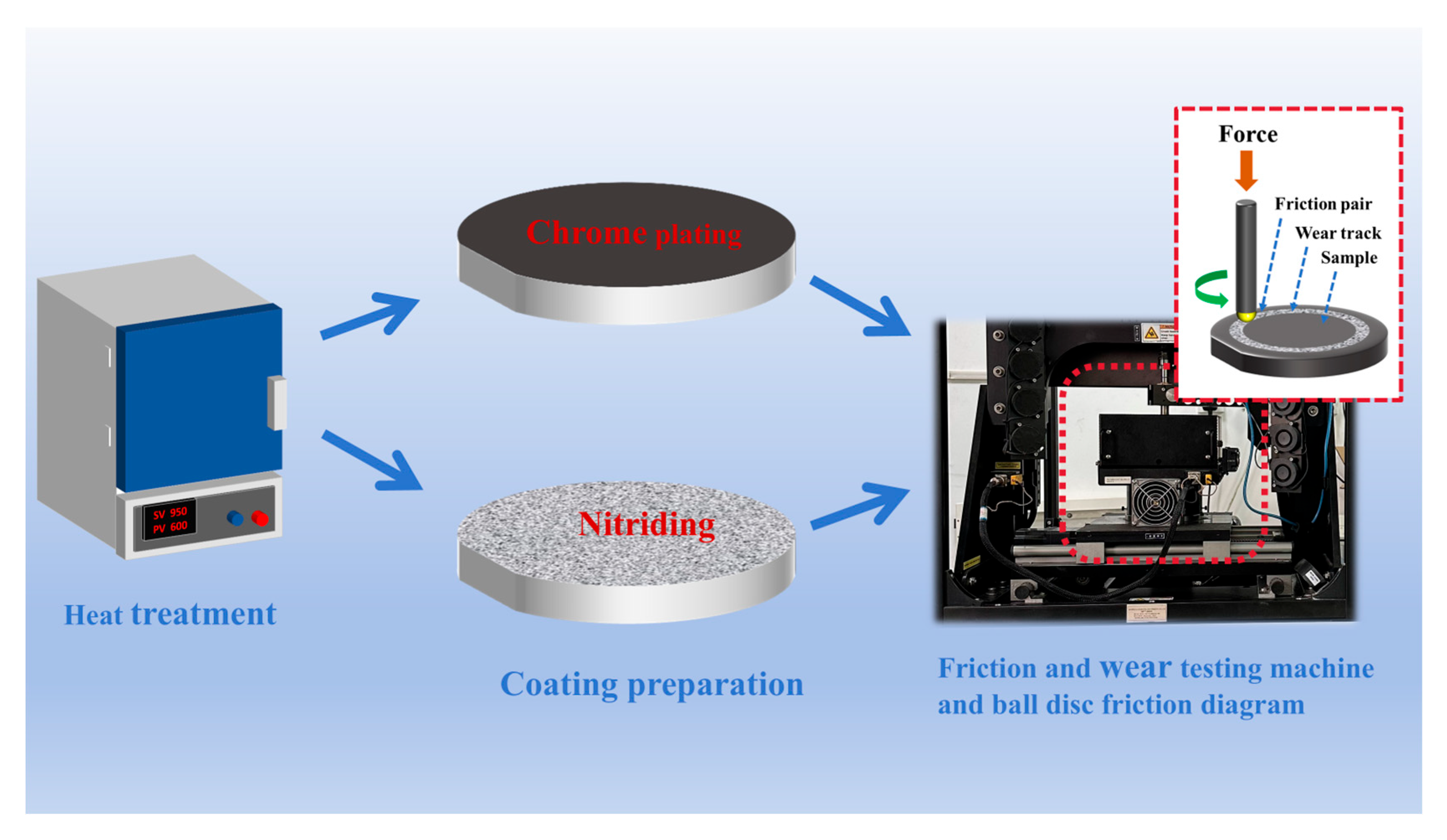
2.1. Coating Preparation

The base material is 2Cr3Mo3VA mold steel. The detailed chemical composition can be found in Table 1. These compositional data were supplied by the material supplier. Prior to surface treatment, the base material was subjected to heat treatment. Normalization: the base material, hot-work die steel, was heated to 960 °C, held at this temperature for 3 h, and then cooled in air. Quenching: the hot-work die steel was heated to 1040 °C, held at this temperature for 1 h, and then quenched in oil. Tempering: the steel was tempered at 580 °C for 4 h, followed by a second tempering at 620 °C for 4 h to achieve optimal mechanical properties. The heat treatment process is illustrated in Figure 1. The material was cut into disc-shaped specimens with the dimensions shown in Figure 2 using an electrical discharge machining (EDM) wire cutter. The specimens were then ground with 200# to 1200# sandpaper, rinsed with deionized water, ultrasonically cleaned in an acetone solution at room temperature for 15 min, and subsequently dried with cold air.

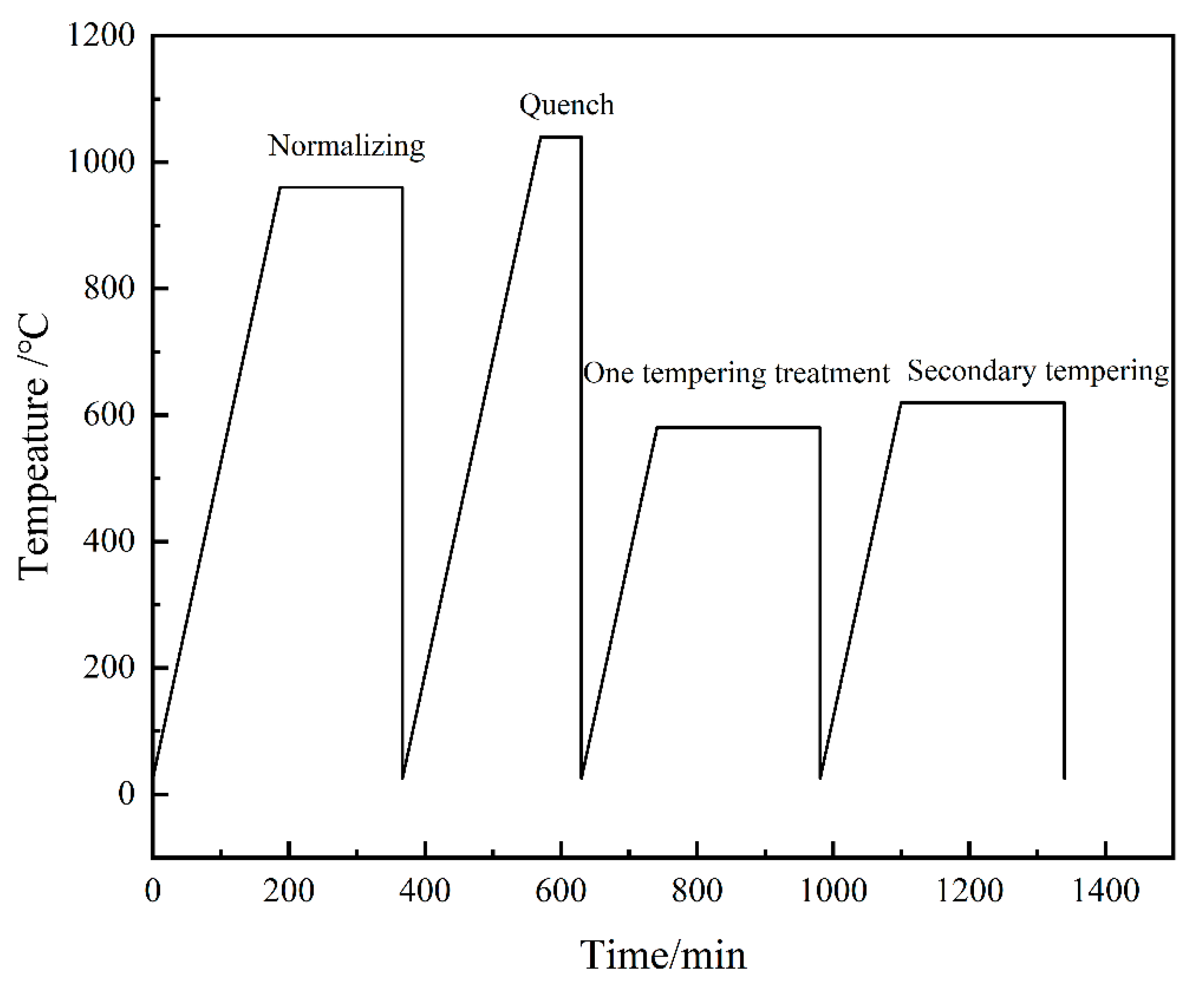
2.1.1. Surface Treatments

Cut the heat-treated sample into the size shown in Figure 2, and then proceed with surface chrome plating treatment. The preparation process parameters for electroplated chromium are as follows: CrO3 concentration of 250 g/L, H2SO4 concentration of 2.5 g/L, current density of 20 A/dm2, and temperature of 60 °C. For another set of samples, the heat-treated specimens were subjected to nitriding surface treatment. The nitriding process is as follows: First, the samples were cleaned. Then, they were preheated at a constant temperature of 350 °C for 40 min. Subsequently, the samples were nitrided for 2 h in a nitriding salt bath (consisting of base salt and adjusting salt) at 500 °C in a box resistance furnace under nitrogen protection. Next, the samples were oxidized for 40 min in an oxidizing salt bath at 380 °C. Finally, the samples were cleaned, dried, and then immersed in oil.

2.1.2. Microstructural and Property Characterization of Chromium Plating/Nitriding

The surface coating and cross-sectional morphology of the samples before and after wear were examined using a field-emission scanning electron microscope (JSM-IT800, JEOL, Tokyo, Japan). Elemental distribution analysis of the coating surface and wear tracks was performed using Energy Dispersive Spectroscopy (EDS) techniques. The crystal structure was characterized using an X-ray diffractometer (Bruker D8, Bruker, Billerica, MA, USA) with Cu-Kα radiation at 40 kV and 40 mA. The X-ray diffractometer was operated with a Cu target, a scanning range of 20° to 90°, and a scanning speed of 6°/min. Microhardness tests were conducted using a microhardness tester (HVT-1000, HYDAC, Sulzbach/Saar, Germany). This instrument is used to measure surface microhardness at a certain depth, with a load of 50 g and a dwell time of 15 s. After polishing the surface of the samples, microhardness tests were performed at five uniformly distributed points on the structure, and the average value of the data points and the standard deviation of the data set were calculated. The wear track’s cross-sectional hardness was evaluated via nanoindentation (Keysight G200, Keysight, Santa Rosa, CA, USA).

2.1.3. Tribological Properties

Wear tests were conducted using the MFT-5000 high-temperature friction and wear tester (Rtec-Instruments, San Jose, CA, USA). The tribological evaluations employed a ball-on-disk setup, utilizing a 9.525 mm diameter Si3N4 ball as the upper specimen. The specific schematic diagram is shown in Figure 3. The prepared samples were cleaned with ethanol and then air-dried. The tribological test parameters are as follows: the test temperatures were room temperature and 700 °C, the test load was 50 N, the sliding radius was 15 mm, the sliding linear velocity was 0.628 m/s, and the total sliding duration was 30 min. The testing rotational speed was 400 rpm. Both the chromium-plated samples and the nitrided samples were tested for friction and wear at room temperature and at 700 °C. The specific parameters of the above experiments are determined based on the working conditions in actual industrial production. In the following article, different samples were numbered and named, as shown in Table 2.
During the tests, automatic heating was achieved using a resistor, and automatic temperature regulation and control were realized using a thermocouple and a temperature controller. The friction coefficient was measured using a microcomputer module. The wear surface morphology was modeled and analyzed using a laser confocal microscope (LCM) (OLS5100, Evident Scientific, Waltham, MA, USA). The wear rate was calculated through 3D surface profiling. Five cross-sections at equal distances from the wear track were selected, and the average cross-sectional area was calculated. The wear track volume V was determined by multiplying the average cross-sectional area by the length of the wear track. The wear rate calculation formula is as follows:
Wear   rate = V NL mm 3 / Nm ,
In the formula, V represents the wear volume (mm3), N represents the load (N), and L represents the total sliding distance (m).

3. Results and Discussion

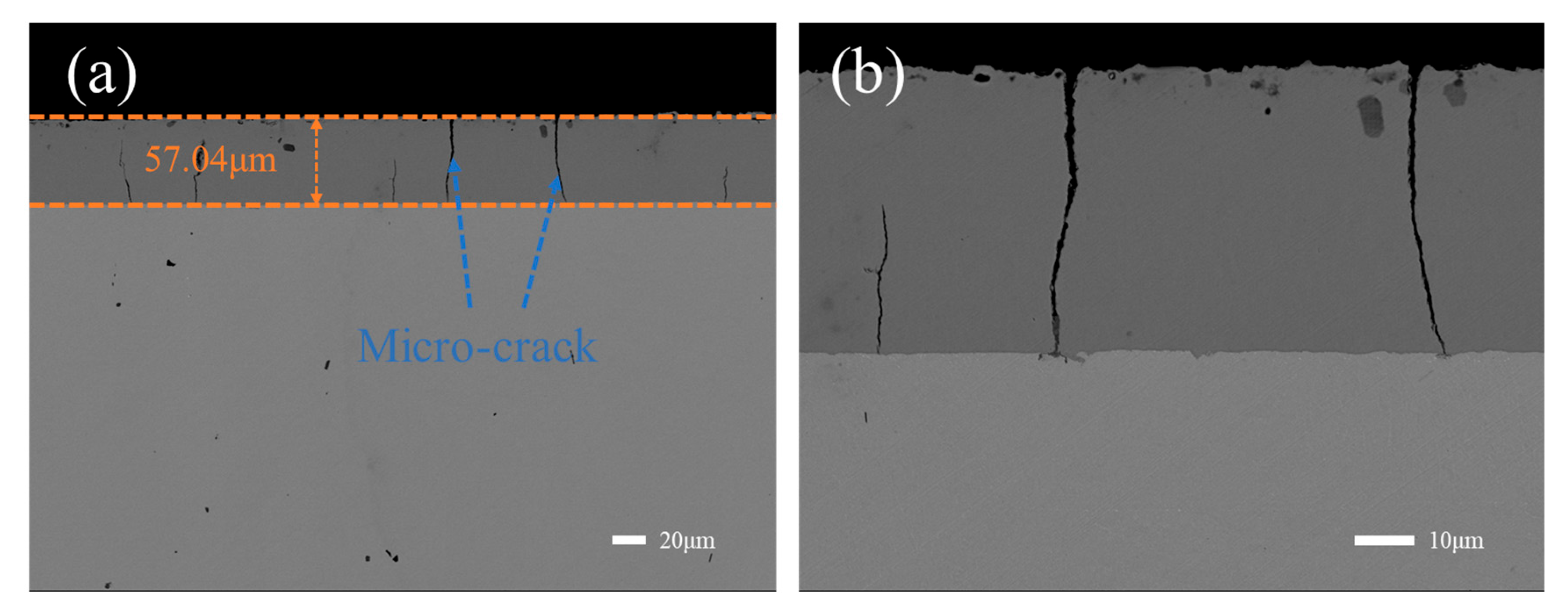
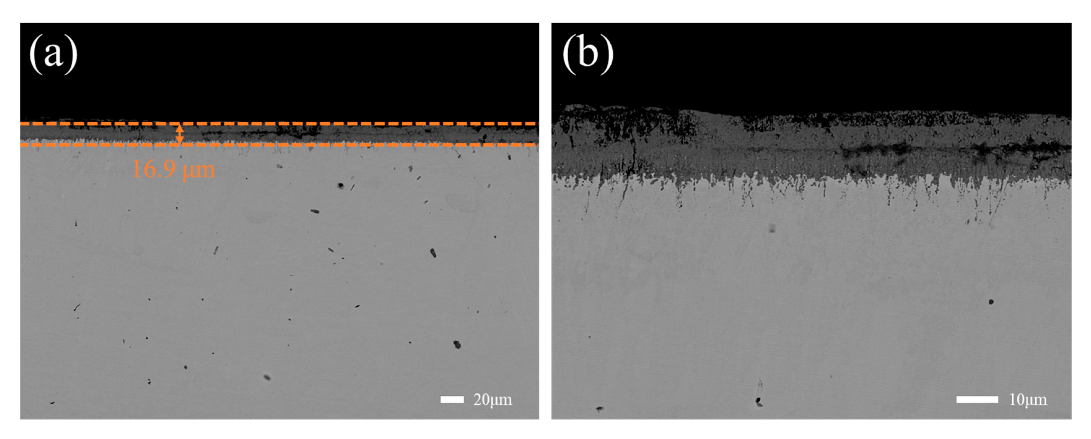
3.1. Microstructure of the Coating

Figure 4 is the cross-sectional morphology of the chromium plating layer. There are micro-cracks in the cross section of the coating, as shown in the arrow in Figure 4a. From the cross-sectional morphology of the chromium plating layer in Figure 4b, it can be seen that the cracks are distributed inside the chromium plating layer and do not extend to the inside of the substrate. This is due to the weak plastic deformation ability of metal chromium in the electroplating process. Under the combined action of electrochemical reaction and stress, the stress release in the chromium plating layer will produce cracks [25]. Although these micro-cracks do not directly penetrate into the matrix, the cracks are easy to expand and connect under the action of thermal stress and other factors, extending from the surface to the matrix. Then, the micro-cracks expand horizontally along the interface between the coating and the substrate, resulting in a large area of peeling off of the coating and losing the protective effect on the substrate [26].
In Figure 5a,b, it can be clearly seen that the nitriding layer is loose and there are many veins extending into the matrix. According to relevant research, due to the coarse original structure and high nitrogen potential, the permeable layer after nitriding will have defects such as loose compound layer and vein nitride [27]. Compared with the obvious interface between the chrome plating layer and the substrate, the existence of the nitriding diffusion layer can buffer the stress [26].

3.2. Friction Coefficient and Wear Rate of the Coating

It can be seen from Figure 6 that the surface hardness of the sample after nitriding is the highest, and the average hardness is 1087.9 Hv. The surface hardness of the sample after chromium plating is 975.5 Hv. It can be seen from Figure 7 that the surface hardness of 1-1 and 2-1 samples is almost the same as that of the samples without wear test. This also shows that the friction and wear experiments at room temperature have little effect on the hardness of the sample surface. It can be seen from Figure 7 that the surface hardness of the sample after high-temperature wear is lower than that of the sample after room-temperature wear. The average hardness of sample 1-2 was 401.0 Hv, while that of sample 2-2 was 566.1 Hv. This shows that the surface hardness of the two samples decreases with the increase in temperature. At the same time, it can be seen that the surface hardness of the chromium plating layer is lower than that of the nitriding layer. It can be seen from the wear rate trend in Figure 8 that the wear rate of the 2-1 sample is the lowest (10.67 × 10⁻⁶ mm3/N·m), while the wear rate of the 1-2 sample is the highest (42.57 × 10⁻⁶ mm3/N·m). The data show that the wear rate of the nitrided layer at 700 °C is about 38% lower than that of the chrome-plated layer, and the wear rate of the nitrided layer at room temperature is about 50% lower than that of the chrome-plated layer, indicating that the nitrided layer has better wear resistance than the chrome-plated layer.
Figure 9 is the curve of the friction coefficient of 1-1, 1-2, 2-1, and 2-2 specimens with the change of sliding time. The sample experienced two stages in the friction process at different temperatures: running stage and stable stage. When the Si3N4 balls of the friction pair first came into contact with the surface of the sample, the friction resistance increased rapidly under the action of the asperities on the surface; that is, the friction coefficient of the running and stage increased rapidly. In the stable wear stage, the friction coefficient basically fluctuates in a constant value. The average friction coefficients of 1-1, 1-2, 2-1, and 2-2 samples are 0.6084, 0.4442, 0.7063, and 0.2740, respectively. The data show that the friction coefficient of the two samples gradually decreases with the increase in wear temperature. This is due to the softening of the material at high temperatures. It can be seen from the average friction coefficient of the two samples at different friction temperatures that the average friction coefficient at 700 °C drops sharply, which is due to the intensification of material surface softening and the formation of a continuous oxide film on the surface. The results show that the nitriding treatment has a certain friction drag reduction effect, which is because the nitriding layer with higher hardness effectively enhances the plastic deformation resistance of the alloy compared with the matrix.
In the process of high-temperature wear, friction heat, ambient temperature, and load will cause plastic deformation, dynamic recovery, and recrystallization of the sample, resulting in the change of the performance of the substructure, thus affecting the wear behavior [28]. Figure 10 shows the hardness distribution of the wear cross section. The cross-section hardness curve divides the sample into three parts: coating area, coating/substrate bonding area, and substrate area. It was found that the hardness of the coating was higher than that of the substrate after wear at room temperature and 700 °C. It can be seen from Figure 10a,b that the coating hardness of 1-2 and 2-2 samples after wear at high temperature 700 °C is lower than that of 1-1 and 2-1 samples after wear at room temperature. This can be attributed to the increased softening of the sample caused by the increase in temperature. It can also be seen from Figure 10 that the hardness of the coating/substrate bonding zone is higher than that of the substrate. The hardness of the matrix is also affected by the temperature, resulting in a decrease in hardness. This softening of the sample is intensified due to the increase in temperature, which leads to the delamination and spalling of the generated oxide layer, resulting in severe oxidative wear and ultimately a decrease in hardness. This delamination phenomenon may further aggravate the damage degree of the sample surface.

3.3. Morphology and Compositional Analysis of the Worn Surface

Figure 11a shows the XRD pattern of chromium-plated samples after friction at different temperatures for 30 min. It can be seen that the surface phase of the sample is mainly a Cr-containing phase when the 1-1 sample is worn at room temperature. The phase of Cr can also be observed in the X-ray diffraction pattern of 1-2 samples at a high temperature of 700 °C. These are mainly the phases of the coating. At the same time, it can be found that the oxide peak intensity of Cr gradually increases in the XRD pattern of 1-2 samples. It can be known that the XRD phase has a significant change with the increase in temperature. It is mainly related to the increase in temperature oxidation. Figure 11b shows the XRD pattern of the nitrided sample after friction at different temperatures for 30 min. It can be seen that the nitrided layer on the surface of the 2-1 sample is mainly ε phase (Fe2–3N), which is also consistent with the results of other scholars [29,30]. In the salt bath nitriding process, the cyanate ion (CNO) in the salt bath decomposes to produce active nitrogen atoms. These active nitrogen atoms gradually aggregate on the surface of the material, and then diffuse to the lattice gap of the material under the impetus of the nitrogen potential. With the extension of nitriding time, the content of solid solution nitrogen atoms in the material increases gradually. Finally, a layer of iron nitride (ε-phase) is formed on the surface of the material, which has high hardness and wear resistance. In the XRD pattern of 2-2 samples in Figure 11b, there is not only ε phase (Fe2–3N), but also Fe oxide phase. The change of the above phase is mainly due to the increase in oxidation caused by the increase in friction and wear temperature, which makes the oxide of Fe appear.
Figure 12 and Figure 13 show the microstructure image and the corresponding element distribution of the wear scar surface of the chrome-plated sample and the nitrided sample, respectively. Figure 12a is the wear scar microstructure diagram and element distribution diagram corresponding to the 1-1 sample. It can be seen from Figure 12a that there are a large number of flake thin layers, fish scale thin layers, furrows, and scratches. From the corresponding element distribution map, it can be seen that these flake thin layers and fish scale thin layers are oxides of Cr. At room temperature, the surface of the chromium plating layer will undergo oxidation reaction due to flash heat phenomenon, forming a thin layer of oxide. During the wear process at room temperature, the oxide film is weak and easy to peel off. The flake thin layer formed granular debris after sliding friction. This wear debris will cause furrows and scratches on the material when sliding, thereby accelerating the wear of the material. It can be seen that the wear mechanism of the chromium plating layer at room temperature is dominated by abrasive wear and accompanied by slight oxidative wear. Figure 12b is the wear scar microstructure diagram and element distribution diagram corresponding to the 1-2 sample. It can be observed in Figure 12b that there are spalling pits, and there are also a large number of flake thin layers, gullies, and scratches. It can be seen from the corresponding element distribution map that the surface of the wear scar has been completely covered by the oxide film. Compared with the wear surface at room temperature, the wear surface after sliding wear at 700 °C has wider and deeper gully traces, and the ploughing traces basically disappear. In addition, the correlation between the appearance of the gully phenomenon and the wear mechanism is significant. Under the condition of high-temperature wear, the surface of the sample is continuously worn and peeled off under the action of high temperature and friction, and gradually forms a gully-like morphology. The evolution of this microstructure will lead to a significant increase in surface roughness, thereby reducing the stability of the friction coefficient and weakening the wear resistance of the material. It can be seen that the wear mechanism of chrome-plated samples at 700 °C is the combined effect of oxidation wear, adhesive wear, and abrasive wear [31]. Figure 13a is the micro-graph of the wear scar and the element distribution map corresponding to the 2-1 sample. It can be observed in Figure 13a that there are some flake thin layers and furrows. From the corresponding element distribution map, it can be seen that the flake thin layer in the wear scar should be the oxide of Fe. It is shown that the wear form of the 2-1 sample is mainly adhesive wear at room temperature, accompanied by slight oxidative wear. Figure 13b is the wear scar microstructure diagram and element distribution diagram corresponding to the 2-2 sample. It can be seen from the corresponding element distribution map that the surface of the wear scar has been completely covered by the oxide film. The wear process generates an oxide film on the contact surface, where wear debris becomes thermally compacted and strongly bonded to the track under elevated temperatures and material softening. This results in the formation of a smooth, wear-resistant tribolayer that functions as a solid lubricant, effectively lowering both the coefficient of friction and wear rate [32,33,34]. The dominant wear mechanisms are identified as oxidative and abrasive wear.
Figure 14a–d shows the three-dimensional topography and corresponding cross-section curves of the wear traces of samples 1-1, 1-2, 2-1, and 2-1 (Figure 14(a1)–(d1)). It can be seen from Figure 14(a1,b1) that the width and depth of the wear scar of the chrome-plated sample at high temperature are 1956.93 μm and 82.33 μm, respectively. The width and depth of the wear scar at room temperature are 2036.73 μm and 52.33 μm, respectively. The wear depth and wear volume at high temperature are larger than those at room temperature. This can be attributed to the softening of the sample caused by the increase in temperature, so that the wear is more serious. This also corresponds to the wear rate of Figure 8. It can be seen from Figure 14(c1,d1) that the width and depth of the wear scar of the nitrided sample at high temperature are 1479.76 μm and 45.35 μm, respectively. The width and depth of the wear scar at room temperature are 1829.06 μm and 11.13 μm, respectively. This also shows the same rule as the chrome-plated sample. The results show that high temperature will soften the material and make the wear resistance worse. The continuous Fe oxide film formed by the nitriding layer at 700 °C has a lubricating effect, which significantly reduces the friction coefficient and wear rate. However, due to the micro-crack propagation and softening effect of the chromium plating layer, the oxide film is easy to peel off, resulting in increased abrasive wear [26]. Thus, the nitrided layer exhibits better wear resistance under high-temperature wear. The wear resistance of the nitriding layer at 700 °C and room temperature is better than that of the chromium plating layer.

4. Conclusions

In this study, the chromium plating layer and nitriding treatment were prepared on the surface of the matrix material 2Cr3Mo3VA hot work die steel. The tribological properties and wear mechanism of two different surface treatments at room temperature and 700 °C were studied. The following conclusions were obtained:
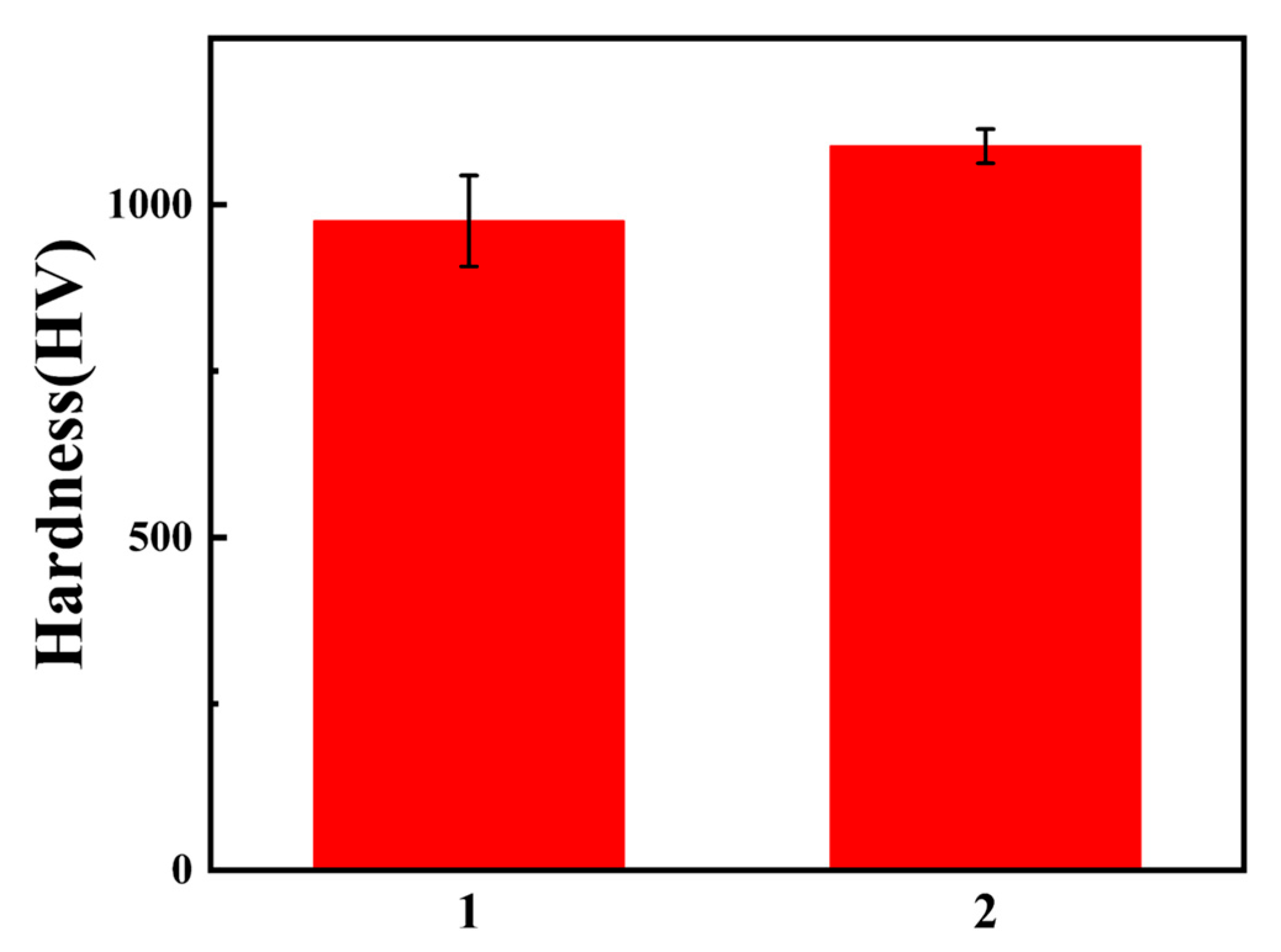
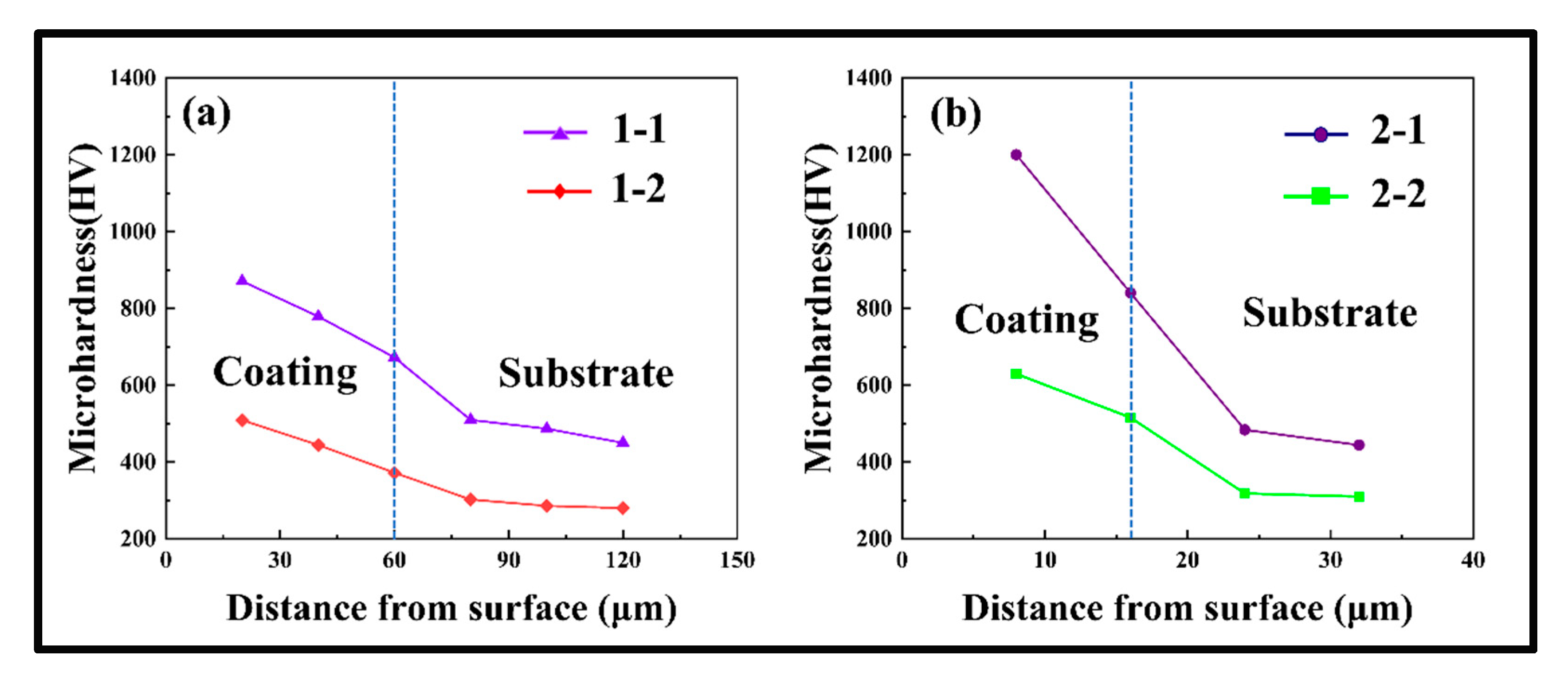
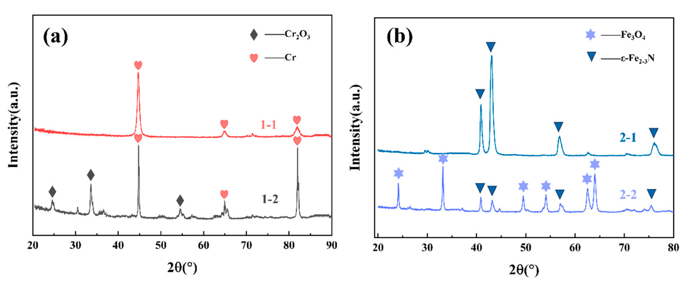
  • The chromium plating layer and nitriding treatment on the surface of 2Cr3Mo3VA hot work die steel were effectively modified. The surface hardness and wear resistance of 2Cr3Mo3VA hot work die steel were improved due to the presence of ε phase (Fe2–3N) in the 2Cr3Mo3VA hot work die steel after nitriding surface treatment. As a result, the surface hardness of the nitrided layer is better than that of the chrome-plated layer.
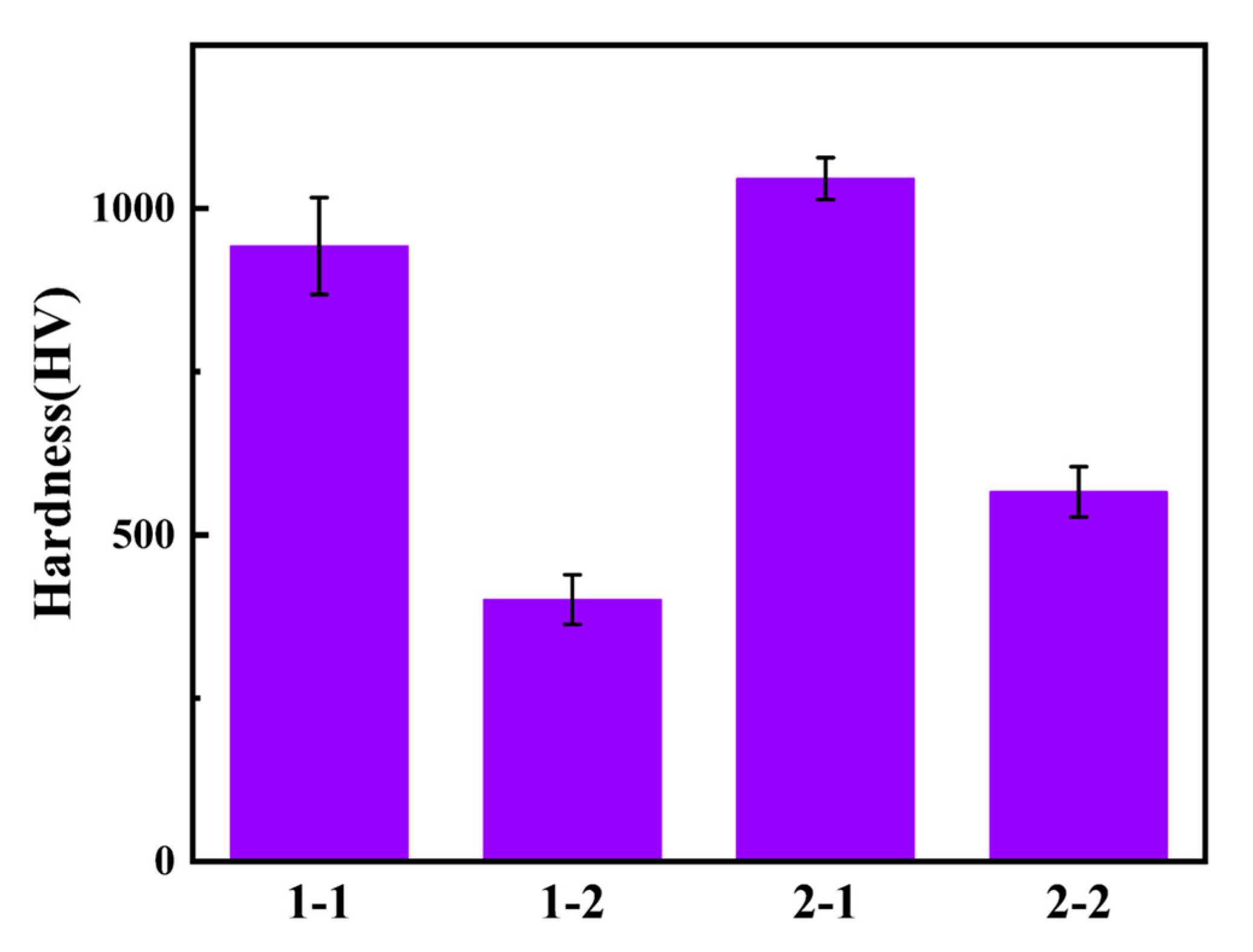
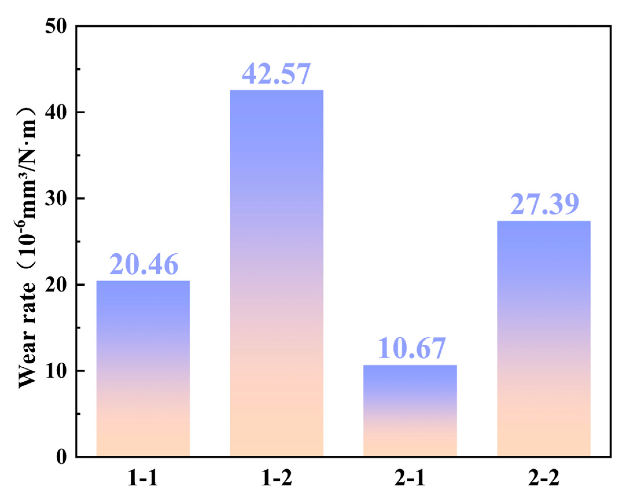
  • The surface hardness of the nitrided sample is higher than that of the chrome-plated sample after room-temperature wear or 700 °C high-temperature wear. At the same time, the wear rate of the nitrided layer at 700 °C is about 38% lower than that of the chromium plating layer, and the wear rate of the nitrided layer at room temperature is about 50% lower than that of the chromium plating layer, indicating that the nitrided layer has better wear resistance than the chromium plating layer.
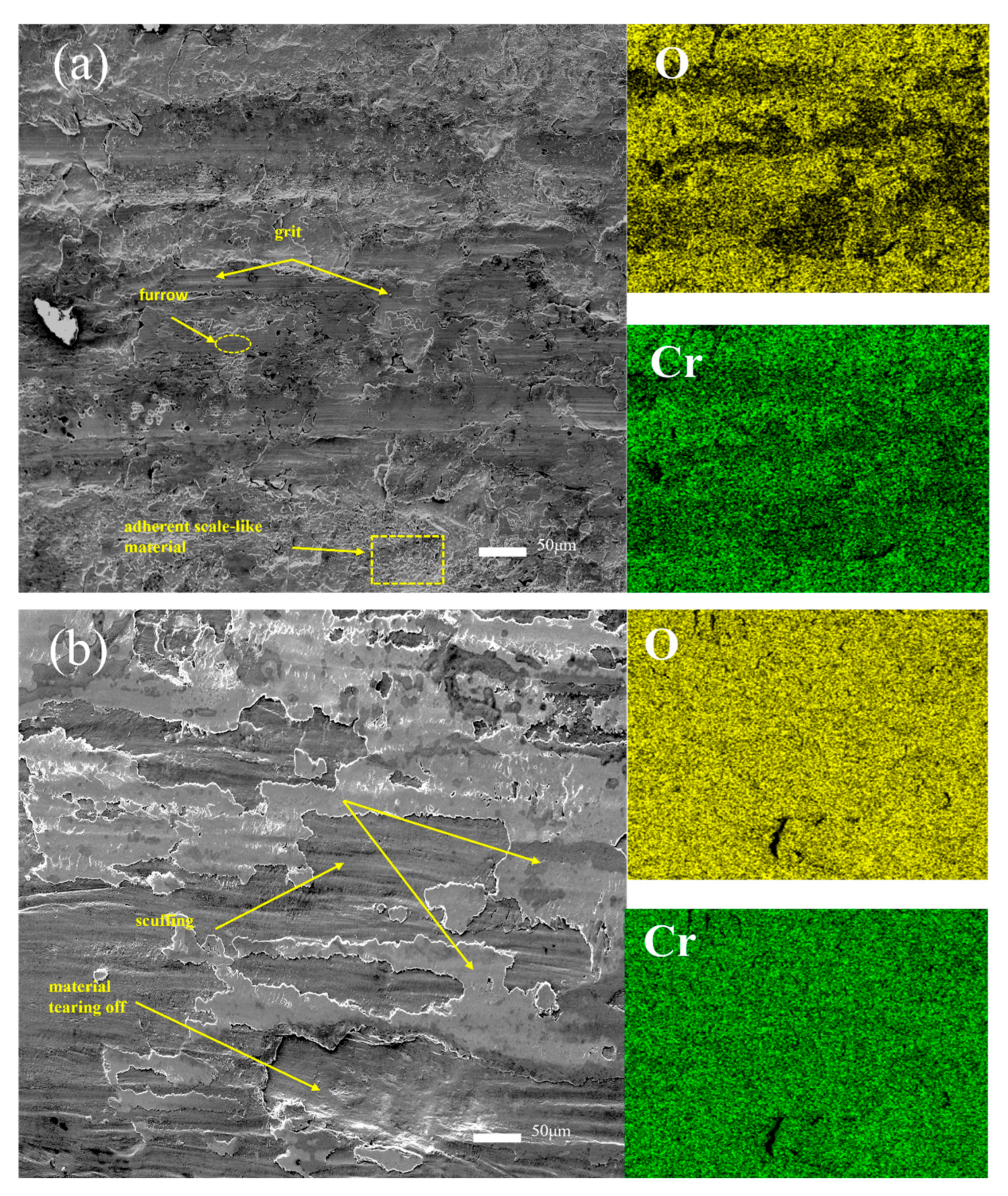
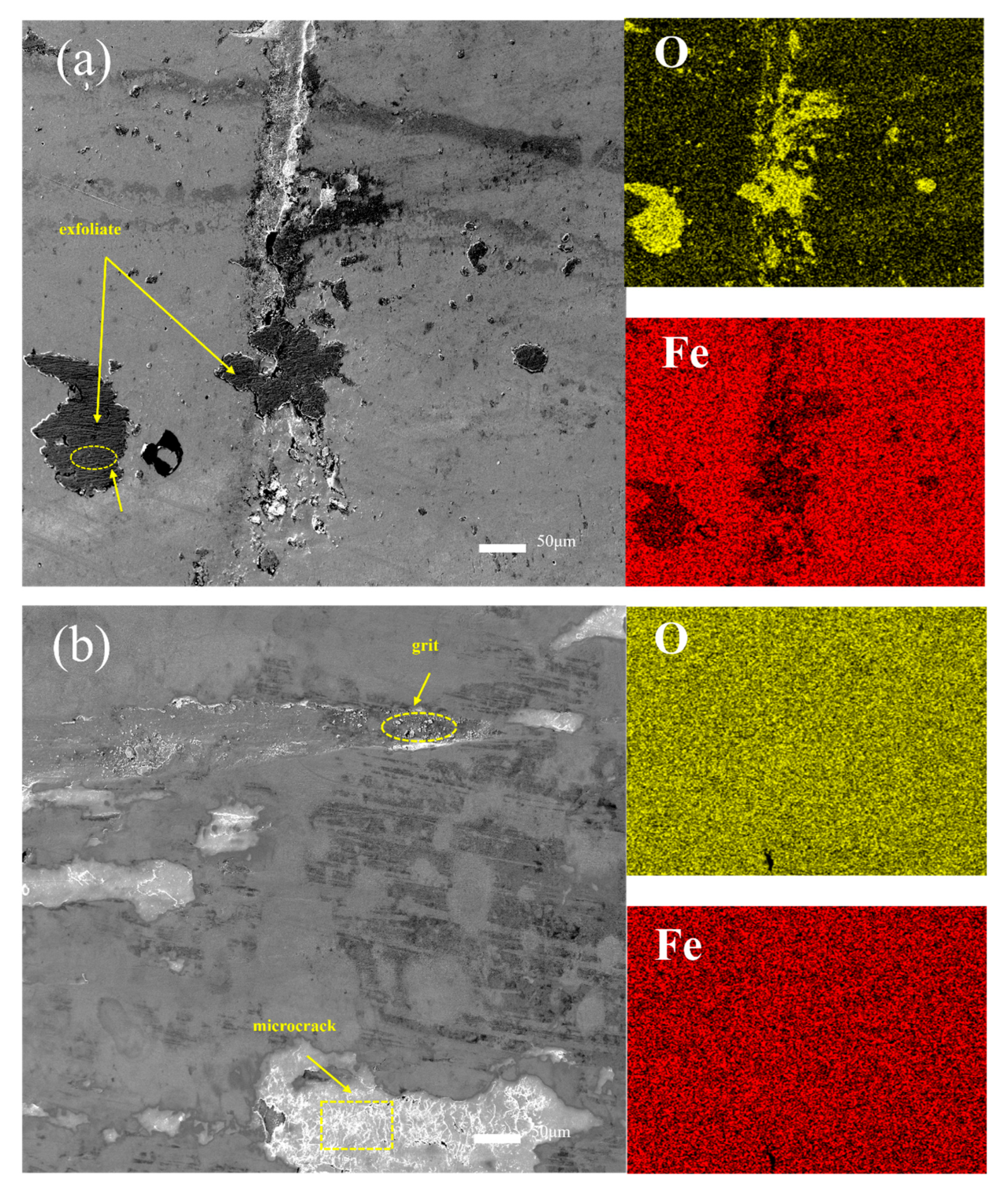
  • The wear mechanism of chromium coating at room temperature is mainly abrasive wear accompanied by slight oxidation wear. The wear mechanism at 700 °C is the combined effect of oxidation wear, adhesive wear, and abrasive wear. The wear mechanism of the nitrided layer at room temperature is mainly adhesive wear, accompanied by slight oxidative wear. The wear mechanism at 700 °C is mainly oxidation wear and abrasive wear.
  • The research results provide important theoretical and experimental basis for surface modification of hot work die steel, especially in improving die life and workpiece quality in high-temperature environment. Future work should focus on further research on the wear mechanism of the coating under more temperature parameters, and explore the high-temperature wear mechanism of more different surface modification technologies, so as to provide a more comprehensive solution for the surface modification technology of hot work die and aerospace parts, and promote technological progress and application expansion in related fields.

Author Contributions

Conceptualization, Methodology, Investigation, and Data Curation, W.Z. (Wei Zhang 1) and J.Z.; Writing—Original Draft, W.Z. (Wei Zhang 2); Software, S.W. and C.Z.; Conceptualization and Writing—Review and Editing L.C., Z.S., X.W. and C.D.; Methodology, Study Design, and Writing—Review and Editing, F.M., C.C. and C.Z. All authors have read and agreed to the published version of the manuscript.

Funding

This project was supported by the Frontier Exploration Projects of Longmen Laboratory (No. LMQYTSKT011), the Natural Science Foundation of Henan Province (No. 242300420020), the Program for Science & Technology Innovation Talents in Universities of Henan Province (No. 25HASTIT007), and the Postdoctoral Research Project of Henan Province (No.HN2025145 and No. HN2025146).

Data Availability Statement

The raw data supporting the conclusions of this article will be made available by the authors on request.

Acknowledgments

We wish to take this opportunity to thank the Provincial and Ministerial Co-construction of Collaborative Innovation Center for Non-ferrous Metal New Materials.

Conflicts of Interest

Jian Zhang, Liuliang Chen, Wei Zhang, and Zhenhuan Sun are employed by Henan Zhongyuan Special Steel Equipment Manufacturing Co., Ltd. The remaining authors declare that the research was conducted in the absence of any commercial or financial relationships that could be construed as a potential conflict of interest.

References

  1. Kashani, H.; Amadeh, A.; Ghasemi, H.M. Room and high temperature wear behaviors of nickel and cobalt base weld overlay coatings on hot forging dies. Wear 2007, 262, 800–806. [Google Scholar] [CrossRef]
  2. Kumar, S.; Maity, S.R.; Patnaik, L. Friction and tribological behavior of bare nitrided, TiAlN and AlCrN coated MDC-K hot work tool steel. Ceram. Int. 2020, 46, 17280–17294. [Google Scholar] [CrossRef]
  3. Mellouli, D.; Haddar, N.; Köster, A.; Ayedi, H.F. Hardness effect on thermal fatigue damage of hot-working tool steel. Eng. Fail. Anal. 2014, 45, 85–95. [Google Scholar] [CrossRef]
  4. Yang, C.; Jing, C.; Fu, T.; Lin, T.; Guo, W.; Liu, N. Effect of TiC addition on the microstructure and properties of laser cladding Ni60A coatings on H13 steel surface. Mater. Today Commun. 2024, 38, 107904. [Google Scholar] [CrossRef]
  5. Yang, X.; Li, C.; Zhang, Z.; Zhang, X.; Gu, J. Effect of cobalt-based coating microstructure on the thermal fatigue performance of AISI H13 hot work die steel. Appl. Surf. Sci. 2020, 521, 146360. [Google Scholar] [CrossRef]
  6. Lu, J.Z.; Cao, J.; Lu, H.F.; Zhang, L.Y.; Luo, K.Y. Wear properties and microstructural analyses of Fe-based coatings with various WC contents on H13 die steel by laser cladding. Surf. Coat. Technol. 2019, 369, 228–237. [Google Scholar] [CrossRef]
  7. Liu, B.; Wang, B.; Yang, X.; Zhao, X.; Qin, M.; Gu, J. Thermal fatigue evaluation of AISI H13 steels surface modified by gas nitriding with pre-and post-shot peening. Appl. Surf. Sci. 2019, 483, 45–51. [Google Scholar] [CrossRef]
  8. Beake, B.; Ning, L.; Gey, C.; Veldhuis, S.; Kornberg, A.; Weaver, A.; Khanna, M.; Fox-Rabinovich, G. Wear performance of different PVD coatings during hard wet end milling of H13 tool steel. Surf. Coat. Technol. 2015, 279, 118–125. [Google Scholar] [CrossRef]
  9. Xue, S.; Yang, T.; Guo, R.; Deng, A.; Liu, X.; Zheng, L. Crack analysis of Cr-Mo-V-Si medium-carbon alloy steel in casting die. Eng. Fail. Anal. 2021, 120, 105083. [Google Scholar] [CrossRef]
  10. Klobčar, D.; Tušek, J.; Taljat, B. Thermal fatigue of materials for die-casting tooling. Mater. Sci. Eng. A 2008, 472, 198–207. [Google Scholar] [CrossRef]
  11. Gu, Y.; Xia, K.; Wu, D.; Mou, J.; Zheng, S. Technical Characteristics and Wear-Resistant Mechanism of Nano Coatings: A Review. Coatings 2020, 10, 233. [Google Scholar] [CrossRef]
  12. Qian, H.; Chen, S.; Wang, T.; Cheng, G.; Chen, X.; Xu, Z.; Zeng, Q.; Liu, Y.; Yan, D. Silicon nitride modified enamel coatings enable high thermal shock and corrosion resistances for steel protection. Surf. Coat. Technol. 2021, 421, 127474. [Google Scholar] [CrossRef]
  13. Zhang, J.; Wang, H. Development of offshore wind power and foundation technology for offshore wind turbines in China. Ocean Eng. 2022, 266, 113256. [Google Scholar] [CrossRef]
  14. Chen, H.; Wang, W.; Le, K.; Liu, Y.; Gao, X.; Luo, Y.; Zhao, X.; Liu, X.; Xu, S.; Liu, W. Effects of substrate roughness on the tribological properties of duplex plasma nitrided and MoS2 coated Ti6Al4V alloy. Tribol. Int. 2024, 191, 109123. [Google Scholar] [CrossRef]
  15. Liu, S.; Liu, C.; Yang, Z.; He, L.; Zeng, G.; Zhang, W.; Long, J.; Chang, H. Microstructure, high-temperature corrosion resistance and oxidation properties of (TiVZrCrAl)N high entropy nitride coatings with different N2/Ar ratios. Surf. Coat. Technol. 2024, 476, 130226. [Google Scholar] [CrossRef]
  16. Mirhosseini, S.S.; Mahboubi, F.; Azadfalah, M. Effect of different plasma nitriding durations on the tribological characteristics of nickel-boron-nanodiamond electroless nanocomposite coatings. Surf. Coat. Technol. 2024, 476, 130181. [Google Scholar] [CrossRef]
  17. He, Z.; Wei, W.; Hu, J.; Gu, J. Aluminum-Modified Plasma Nitriding with High Efficiency and Enhanced Performance. Coatings 2024, 14, 1373. [Google Scholar] [CrossRef]
  18. Lausmann, G.A. Electrolytically deposited hardchrome. Surf. Coat. Technol. 1996, 86, 814–820. [Google Scholar] [CrossRef]
  19. Pan, P.; Gao, J.; Si, C.; Yao, Q.; Guo, Z.; Zhang, Y. Tribological properties of TIN coating on cotton picker spindle. Coatings 2023, 13, 959. [Google Scholar] [CrossRef]
  20. Sun, Y.; Liang, Y.; Zhao, O. Local—Flexural interactive buckling behaviour and resistances of high-chromium stainless steel slender welded I-section columns. Eng. Struct. 2020, 220, 111022. [Google Scholar] [CrossRef]
  21. Skripnyak, N.V.; Emelyanova, E.S.; Skripnyak, V.A.; Skripnyak, E.G. Damage of high-chromium steels under deformation in a wide temperature range. In AIP Conference Proceedings; AIP Publishing: Melville, NY, USA, 2017; p. 1909. [Google Scholar] [CrossRef]
  22. Liu, Y.; Sun, Y.; Wu, H. Effects of chromium on the microstructure and hot ductility of Nb-microalloyed steel. Int. J. Miner. Metall. Mater. 2021, 28, 1011–1021. [Google Scholar] [CrossRef]
  23. König, T.; Kimpel, T.; Kürten, D.; Kailer, A.; Dienwiebel, M. Influence of atmospheres on the friction and wear of cast iron against chromium plated steel at high temperatures. Wear 2023, 522, 204695. [Google Scholar] [CrossRef]
  24. Wang, Y.; Hu, X.; Shi, X.; Yuan, Y.; Gao, J.; Zhang, Y. Failure mechanism analysis of electroplated chromium coating in repeated scratch tests under subcritical loads. Wear 2025, 564, 205708. [Google Scholar] [CrossRef]
  25. Beake, B.D.; Ogwu, A.A.; Wagner, T. Influence of experimental factors and film thickness on the measured critical load in the nanoscratch test. Mater. Sci. Eng. A 2006, 423, 70–73. [Google Scholar] [CrossRef]
  26. Fu, H.T.; Zhang, J.; Huang, J.F.; Lian, Y.; Zhang, C.; Gao, W. Comparison of nitrided hot work tool steel and chromium coated 30SiMn2MoVA. China Surf. Eng. 2015, 28, 1–6. [Google Scholar] [CrossRef]
  27. Kumar, A.; Keerti, S.; Jain, J.; Sinha, S.; Tekumalla, S.; Gupta, M. Investigations of Wear Response of Pure Mg and Mg-0.4 Ce-Y2O3/ZnO Nanocomposites Using a Single and Repeated Scratch Tests. Tribol. Trans. 2018, 61, 951–959. [Google Scholar] [CrossRef]
  28. Zhen-Yu, Z.; Zhi-Guo, J.; Qiu-Yang, Z.; Yu, L.; Zhi-Peng, Y.; Cong, D.; Zhong-Yu, P. Research on the construction of gradient nanostructure and anti-tribocorrosion behavior of aluminum alloy surface. Tribol. Int. 2024, 194, 109448. [Google Scholar] [CrossRef]
  29. King, P.C.; Reynoldson, R.W.; Brownrigg, A.; Long, J.M. Cr (N, C) diffusion coating formation on pre-nitrocarburised H13 tool steel. Surf. Coat. Technol. 2004, 179, 18–26. [Google Scholar] [CrossRef]
  30. Feng, L.; Hu, J.; Yan, S.; He, Z.; Shi, J.; Li, J. Effect of high-speed steel surface nitriding treatment on adhesion and wear resistance properties of nitrogen-doped diamond-like carbon coatings. Diamond Relat. Mater. 2023, 136, 110006. [Google Scholar] [CrossRef]
  31. Tima, R.; Mahboubi, F. Ability of plasma nitriding to improve tribological behavior of medium and high boron electroless nickel coatings. Tribol. Int. 2021, 156, 106822. [Google Scholar] [CrossRef]
  32. Jiang, W.; Wang, S.; Deng, Y.; Guo, X. Microstructure stability and high temperature wear behavior of an austenite aging steel coating by laser cladding. Mater. Charact. 2022, 184, 111700. [Google Scholar] [CrossRef]
  33. Derelizade, K.; Rincon, A.; Venturi, F.; Wellman, R.; Kholobystov, A.; Hussain, T. High temperature (900 °C) sliding wear of CrNiAlCY coatings deposited by high velocity oxy fuel thermal spray. Surf. Coat. Technol. 2022, 432, 128063. [Google Scholar] [CrossRef]
  34. Xing, Q.; Feltrin, A.C.; Akhtar, F. Processing, microstructure and high temperature dry sliding wear of a Cr-Fe-Hf-Mn-Ti-Ta-V high-entropy alloybased composite. Mater. Today Commun. 2021, 28, 102657. [Google Scholar] [CrossRef]
Figure 1. Heat treatment process flowchart of 2Cr3Mo3VA steel.
Lubricants 13 00313 g001
Figure 2. Wire Electrical Discharge Machining (WEDM) diagram of the specimen.
Lubricants 13 00313 g002
Figure 3. Test flowchart and ball-on-disc friction diagram.
Lubricants 13 00313 g003
Figure 4. SED diagrams of chromium plating coating cross-section: (a) low SED diagram, (b) high SED diagram.
Lubricants 13 00313 g004
Figure 5. Nitriding section SED diagrams: (a) low SED diagram, (b) high SED diagram.
Lubricants 13 00313 g005
Figure 6. Surface hardness of different samples: no. 1 is the surface hardness of the sample after chromium plating; no. 2 is the surface hardness of the sample after nitriding.
Lubricants 13 00313 g006
Figure 7. Surface hardness of different samples after wear.
Lubricants 13 00313 g007
Figure 8. Wear rates of different specimens.
Lubricants 13 00313 g008
Figure 9. Variation of friction coefficient with time (ad): 1-1 chromium plating sample at room-temperature wear, 1-2 chromium plating sample at 700 °C high-temperature wear, 2-1 nitriding sample at room-temperature wear, and 2-2 nitriding sample at 700 °C high-temperature wear.
Lubricants 13 00313 g009
Figure 10. Hardness distribution of the worn cross-section: (a) chromium plating; (b) nitriding.
Lubricants 13 00313 g010
Figure 11. XRD patterns of surface phases after wear for two types of specimens: (a) XRD patterns of chromium-plated specimens under room-temperature wear and 700 °C high-temperature wear; (b) XRD patterns of nitrided specimens under room-temperature wear and 700 °C high-temperature wear.
Lubricants 13 00313 g011
Figure 12. SEM images of wear scar surface and corresponding element distribution map: (a) room-temperature wear scar map and corresponding element distribution map of chromium-plated 1-1 sample; (b) wear scar diagram and corresponding element distribution diagram of chromium-plated 1-2 samples at 700 °C.
Lubricants 13 00313 g012
Figure 13. SEM images of wear scar surface and corresponding element distribution map: (a) room temperature wear scar map and corresponding element distribution map of nitriding 2-1 sample; (b) wear scar diagram and corresponding element distribution diagram of nitrided 2-2 samples at 700 °C.
Lubricants 13 00313 g013
Figure 14. Three-dimensional topography (ad) and corresponding cross-sectional curves (a1d1): (a,a1) 1-1 chrome-plated specimen under room-temperature wear, (b,b1) 1-2 chrome-plated specimen under 700 °C high-temperature wear, (c,c1) 2-1 nitrided specimen under room-temperature wear, and (d,d1) 2-2 nitrided specimen under 700 °C high-temperature wear.
Lubricants 13 00313 g014
Table 1. Chemical composition of the experimental steel (mass fraction, %).
SteelCSiMnCrMoVPSFe
2Cr3Mo3VA0.220.500.252.792.800.15<0.015<0.015Bal.
Table 2. Comparison table of sample number and wear test conditions.
Sample NumberSurface TreatmentWear Test Temperature
1-1Chromium platingRoom
1-2Chromium plating700 °C
2-1NitrideRoom
2-2Nitride700 °C
Disclaimer/Publisher’s Note: The statements, opinions and data contained in all publications are solely those of the individual author(s) and contributor(s) and not of MDPI and/or the editor(s). MDPI and/or the editor(s) disclaim responsibility for any injury to people or property resulting from any ideas, methods, instructions or products referred to in the content.

