Abstract
The double-piece inner ring ball bearing is an important part of an aero-engine. An excessive bearing temperature leads to bearing thermal expansion, lubricating oil performance degradation, and other problems that seriously affect the service life and reliability of the bearing. Thus, it is important to study the temperature field of a double-piece inner ring ball bearing. In this study, considering the heat exchange of lubricant circulating in the oil tank–tubing–bearing and the influence of the flow field in the bearing chamber on the bearing’s temperature rise, a modified transient thermal network equation for an oil tank–tubing–bearing system was established. Based on ADAMS software and considering the thermal–mechanical coupling effect on the bearing’s contact force, a thermal–mechanical coupling dynamic model for double-piece inner ring ball bearings was established. Combined with the bearing dynamics and modified transient thermal network equation, a thermal–mechanical coupling transient temperature field model for double-piece inner ring ball bearings was constructed. A temperature rise test was carried out on a double-piece inner ring ball bearing, and the accuracy of the bearing temperature rise simulation model was verified by the test results. The model can simulate the oil temperature change process, calculate the heat absorbed by the lubricating oil more accurately, and provide a theoretical basis for the design of bearing and lubrication systems.
1. Introduction
Aero-engine spindle bearings are an important part of aero-engines and are often used under high-speed, high-temperature, heavy-load, and other working conditions. The friction of the bearing and stirring of the lubricant lead to an increase in bearing temperature and a reduction in lubricating viscosity. Excessive bearing temperature is prone to lubrication failure, bearing seizure, and other serious consequences, making it a major element restricting the properties of aero-engines. In conclusion, an exploration of the temperature field in double-piece inner ring ball bearings has engineering value.
There are two main methods for the study of bearing temperature fields, based on finite element or thermal network method. Both schemes use the empirical formula of the friction torque presented by Palmgren [1] or Harris [2] to compute bearing heat. Some scholars have used Computational Fluid Dynamics to study temperature of bearings. Based on finite element simulation, Kim [3] analyzed the temperature rise in a spindle system, and their spindle system model was experimentally verified. Wei Wu et al. [4,5] used the VOF model to numerically simulate and experimentally study the fluid distribution in bearing chambers. The results indicated that the bearing temperature field is affected by the fluid distribution in a bearing chamber. Yang Li [6] established a two-phase flow model for bearings and studied the temperature field in the bearing. The conclusion was that the uneven distribution of fluid in the bearing has an important influence on bearing cooling. Gao [7] used the CLSVOF method to study the flow field in a double-piece inner ring ball bearing. It was concluded that there is an optimal oil supply that maximizes the heat dissipation effect. Li [8] proposed a fluid–solid coupling steady-state temperature field model for angular contact ball bearings based on CFD simulation software to analyze the flow field and temperature field of bearings. Bao [9] established a simplified three-dimensional heat transfer model for double-piece inner ring ball bearings; the CLSVOF method was used to track the oil–air two-phase flow, and the Palmgren method was used to calculate the heat generation. Xu [10] used the local method to calculate the heat generation of a bearing, used the finite element method to establish the temperature rise simulation model of the aero-engine bearing under the condition of composite load, and verified it using a double-rotor experimental device. Tao [11] studied the influence of temperature rise on a dynamic model of a bearing and verified his conclusion by finite element simulation and experiment.
In research based on the finite element method, it is easy for scholars to use CFD simulation software to realize the coupling of the temperature and flow fields; however, research on bearing dynamics cannot be carried out using this method. Some scholars have calculated bearing temperature by using the thermal network method. Winer [12] used a transient thermal method to study tapered roller bearing temperature and verified this method. Bossmann [13] established transient temperature equations for spindles and bearings, then studied the temperature field. Cole et al. [14] compared thermal mesh simulation results with finite element model simulation results and experimental data. They concluded that the simulation results of the thermal mesh model have little error with other data. Neurouth [15] established a steady-state thermal network equation to study the temperature field of thrust bearings and simplified it. Yan, Ke [16] considered the distortion of the spindle system caused by assembly stress, thermal stress, and centrifugal force and established a temperature simulation model for the spindle system. Zheng [17,18] built a new transient thermal network model. In this model, the bearing nodes were divided more densely, and the bearing working environment was simulated using more nodes, which achieved good results. Brossier [19] established a temperature field model of a rolling bearing system and designed a test bench to study the friction power consumption of a rolling bearing. The accuracy of the model was verified by comparison with the experimental results. Lei [20] used a six-component friction torque calculation model to compute the bearing heat and used the steady-state thermal network method to calculate the bearing temperature rise. A coupling simulation model of the dynamics and temperature field of a double-piece inner ring ball bearing was established. This model considered the inconsistency between the oil inlet temperature and the oil outlet temperature, but the oil inlet temperature must be known to calculate the bearing temperature rise. Liu [21] established a thermal–mechanical coupled dynamics model for lubricated rolling bearings that consists of a skidding dynamics model and a transient thermal network model. Dong [22] proposed a transient bearing temperature field prediction method combining the thermal network method and finite element method, and the relationships between time step, calculation efficiency, and calculation results were analyzed.
The flow field of the double-piece inner ring ball bearing has a significant effect on the temperature rise of the bearing, and the temperature rise of the bearing also affects the viscosity of the lubricating oil in the flow field. The working temperature of the bearing is high, the thermal effect is significant, and the thermal–mechanical coupling effect cannot be ignored. Therefore, the relationship between bearing dynamics, flow field, and temperature field should be comprehensively considered.
In summary, this study established a multifield coupling simulation model of the double-piece inner ring ball bearing that comprehensively considers the interaction between the bearing dynamics, flow field, and temperature field. This model solves the problem of the traditional finite element method has of not being able to consider the thermal coupling effect when using CFD simulation to calculate the bearing temperature field and also solves the problem the traditional heat grid method has of achieving thermal–mechanical coupling but being unable to consider the bearing flow field.
In this study, a transient temperature field model of a double-piece inner ring ball bearing was established using the transient thermal network method and considering the recycling of lubricant in an oil tank–tubing–bearing system. A bearing flow field simulation model was established; then, the heat absorption of the lubricant was corrected using the results of the bearing flow field. Using the secondary development of ADAMS, a coupling simulation of the bearing dynamics and transient temperature field was realized. The correctness of the simulation model was verified experimentally.
2. Thermal–Mechanical Coupling Transient Temperature Field Model of Double-Piece Inner Ring Ball Bearing
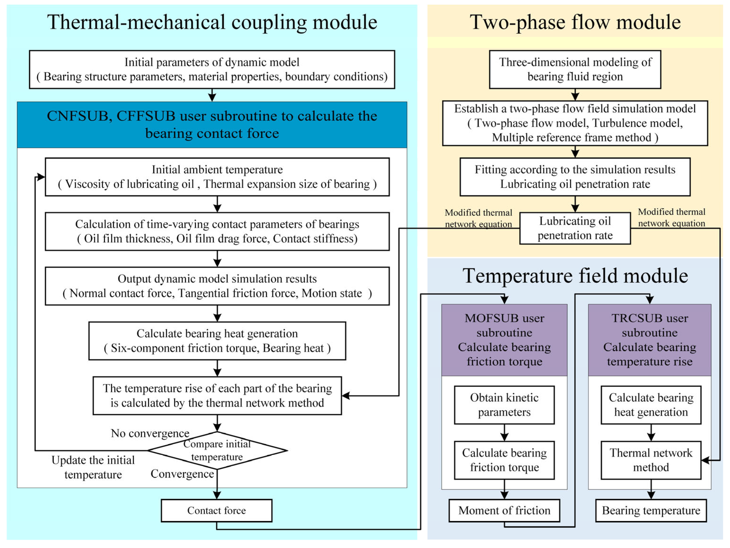
In this section, considering the interaction between the dynamics, temperature field, and two-phase flow field of a double-piece inner ring ball bearing, a thermal–mechanical coupling transient temperature field model of the double-piece inner ring ball bearing based on the secondary development of ADAMS is proposed. A thermal–mechanical coupling dynamic model of the bearing is established; then, the six-component friction torque and heat generation of the bearing are calculated according to the simulation results of the bearing dynamics. Considering the thermal–mechanical coupling and heat exchange of the lubricant circulation process, transient thermal network equations are established. A two-phase flow field simulation model of a double-piece inner ring ball bearing is established, and the simulation results are used to modify the thermal network method. Finally, the thermal–mechanical coupling transient temperature field model of a double-piece inner ring ball bearing is formed. Figure 1 shows the calculation process of the thermal–mechanical coupling transient temperature field model of the double-piece inner ring ball bearing. The theoretical formulas for calculating the bearing temperature rise in the thermal–mechanical coupling and temperature field modules are exactly the same. They calculate the bearing temperature increase separately and play a different role. The calculation of the bearing temperature rise in the thermal–mechanical coupling module is used to realize the thermal–mechanical coupling effect. All the processes of thermal–mechanical coupling in the second section are realized in the thermal–mechanical coupling module. The bearing temperature in the temperature field module is calculated to obtain the bearing temperature rise data that can be extracted, which users only use to obtain the bearing temperature rise.

Figure 1.
Thermal–mechanical coupling transient temperature field model calculation process for double-piece inner ring ball bearing.
2.1. Dynamic Model of Bearing Considering Thermal–Mechanical Coupling Effect
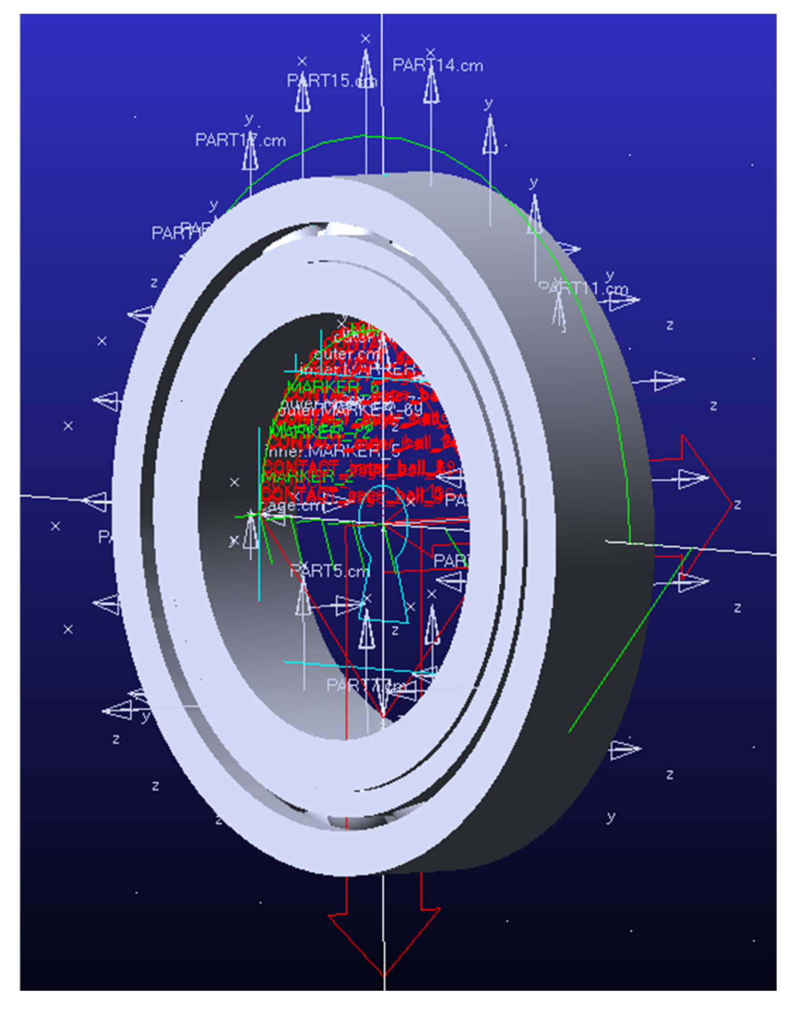
Using the Hertz contact theory and elastohydrodynamic lubrication theory, the comprehensive contact stiffness is the series of Hertz contact stiffness and lubricating oil film stiffness. The thermal effects of bearings and lubricants were considered to calculate the contact force. The thermal–mechanical coupling dynamic model of a double-piece inner ring ball bearing was established using the secondary development of ADAMS, and Figure 2 shows the model diagram.

Figure 2.
Three-dimensional representation of the bearing simulation model in ADAMS.
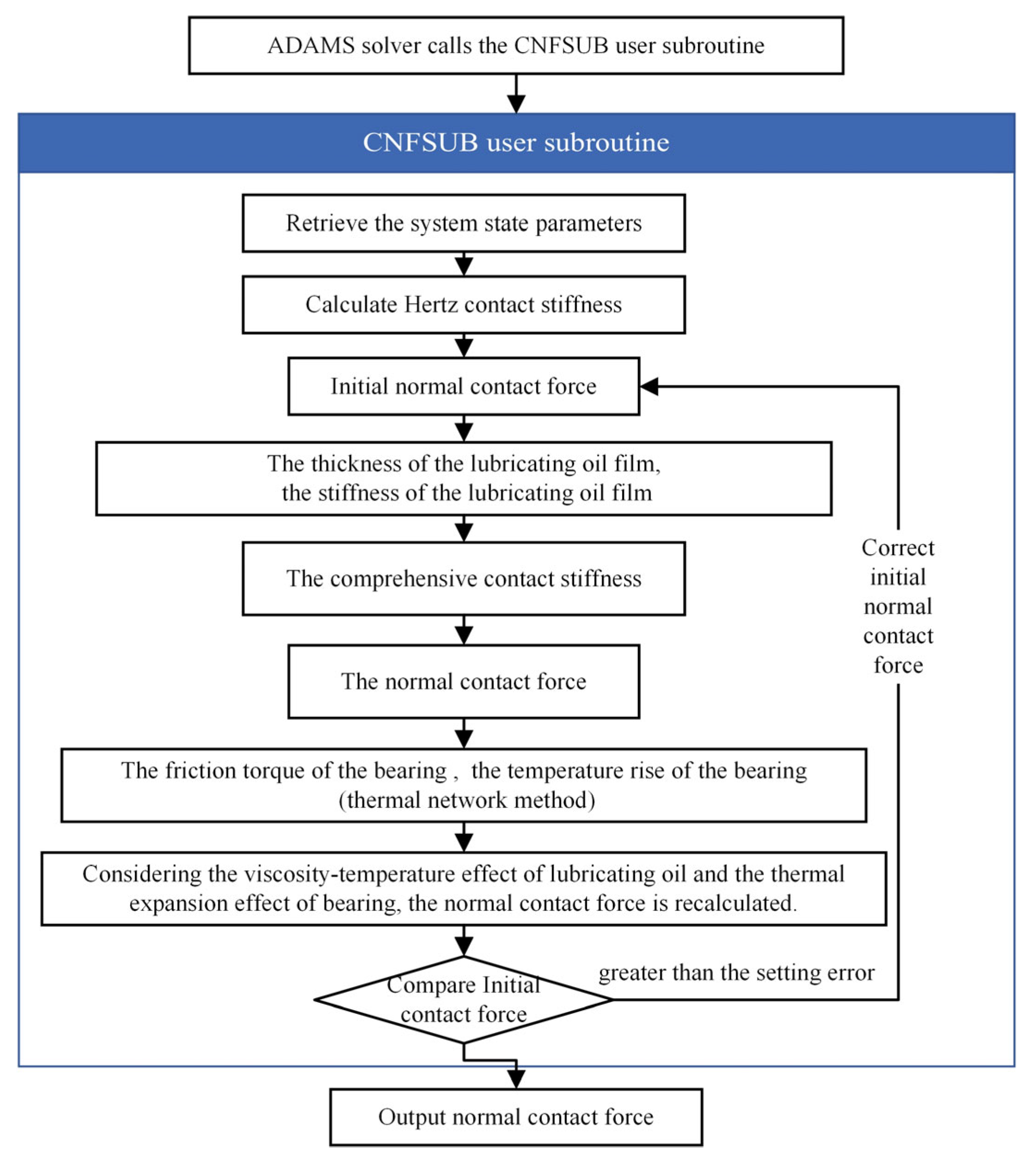
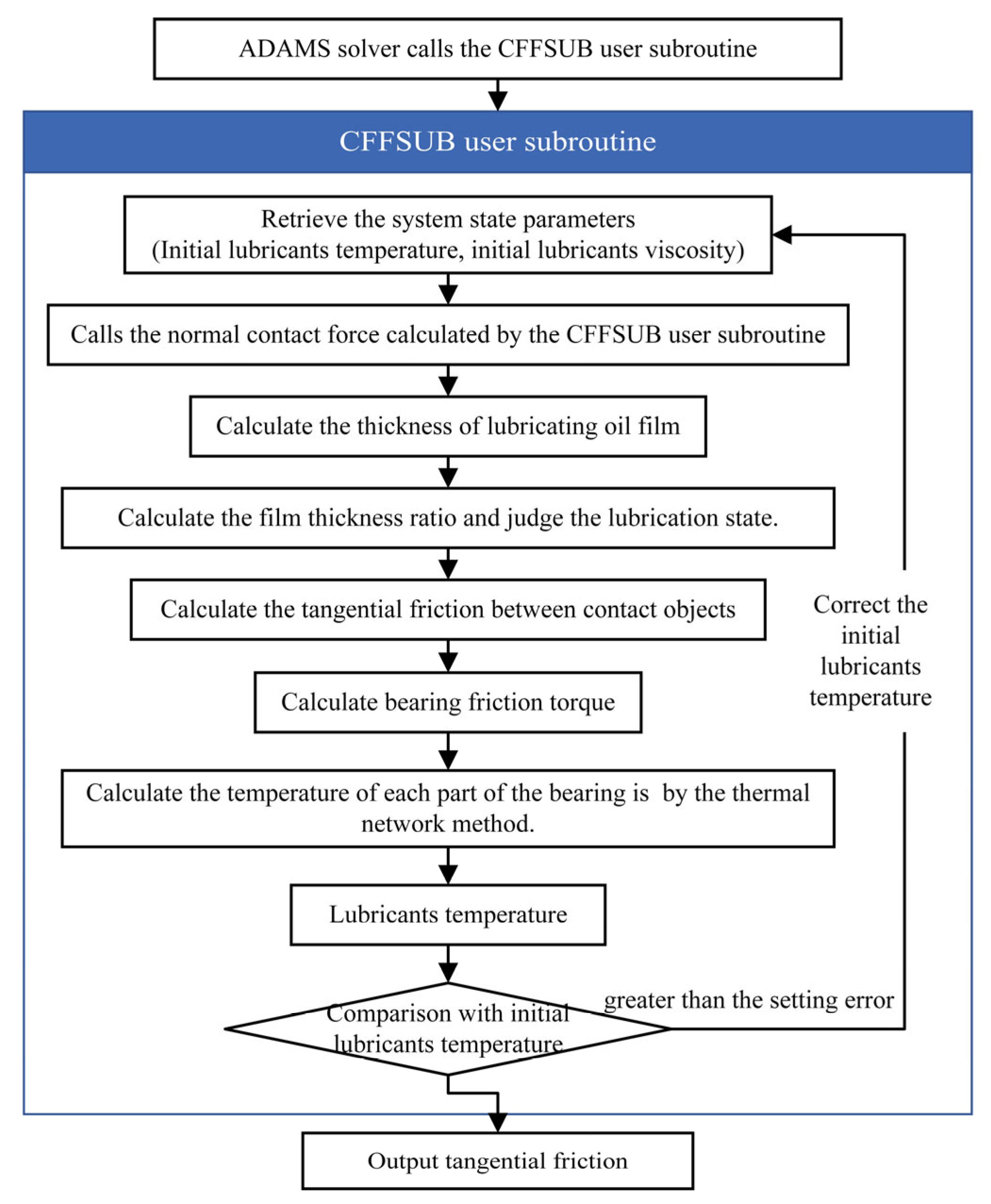
In this model, the outer ring is fixed, the point drive is used on the inner ring to apply a rotational speed, and spatially-fixed loads are applied to the inner ring. The solid–solid contact pairs are set between the inner ring, outer ring, ball, and cage, respectively. The ball and the cage completely rely on the contact force to limit the movement. In this model, the contact force of each part of the bearing is affected by the lubrication state and temperature rise of the bearing. The default contact relationship of ADAMS cannot accurately describe the contact state between the various parts of the bearing. The custom function expression can only provide a limited programming structure and cannot be judged logically. Therefore, it is necessary to use user subroutines to express the complex functional relationships. The CNFSUB (Figure 3) and CFFSUB (Figure 4) user subroutines were written to calculate the normal and tangential contact forces, respectively.
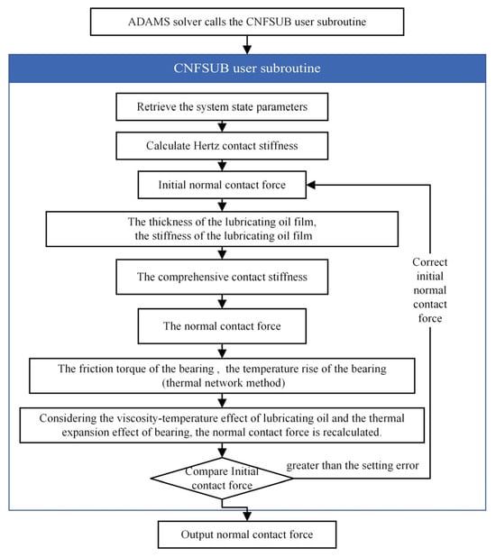
Figure 3.
Calculation process of normal contact force.
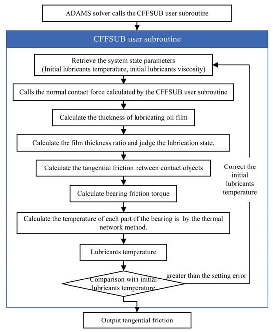
Figure 4.
Tangential contact force calculation process.
The temperature rise leads to the thermal expansion of the bearing and a reduction in lubricating viscosity. The lubricating viscosity affects its stiffness, which affects the comprehensive contact stiffness. Therefore, when calculating the bearing contact force, the effects of temperature should be considered. The calculation formula of the normal contact force is shown in Equation (1):
where Q is the normal contact force, N; K is the comprehensive contact stiffness, N/m; x is the mutual penetration depth of two objects, m; ΔI is the variation in the actual distance of the surface of the two collision parts caused by the thermal effect, m; hmin is oil film thickness, m; e1 is the collision force index; for point contact, e1 is 1.5; cmax is the maximum damping coefficient, generally 0.01% of the comprehensive contact stiffness, N/(m/s); dx/dt is the relative velocity of two colliding parts.
The comprehensive contact stiffness is the series connection of Hertz contact stiffness and lubricant film stiffness. According to the definition of contact stiffness, the stiffness of the oil film can be derived from the oil film thickness formula. The calculation formula for the comprehensive contact stiffness K is shown in Equation (2):
where Kl is Hertz contact stiffness, N/m; Kw is oil film stiffness, N/m.
The formula for calculating the minimum oil film thickness is shown in Equation (3). According to Equations (3) and (4), the formula for calculating the contact force according to the thickness of the lubricating oil film can be obtained, as shown in Equation (5). Following the stiffness definition, the derivative of Equation (5) over hmin directly provides the lubricant film stiffness, as shown in Equation (6):
where Rg is the equivalent radius of curvature in the long axis direction of the contact area, m; U is the dimensionless velocity parameter; G is a dimensionless material parameter; E is the comprehensive elastic modulus of the surface of the ball and raceway, Pa; e is Euler constant; and ep is ellipticity. The parameter calculation process is shown in Reference [23].
The change in contact force caused by the thermal effect of the bearing is simulated by adjusting the distance x between the two model surfaces in the contact force calculation function. The calculation formula for the bearing clearance variation is shown in Equation (7):
where ΔI is the bearing clearance variation, m; σ is the thermal expansion coefficient, °C−1; ΔT is the temperature variation, °C; D is the thermal expansion direction dimension, m (subscripts i, e, and b represent inner ring, outer ring, and ball, respectively).
When calculating the tangential friction between the ball and the bearing rings, the film thickness ratio is used to determine the contact state. The calculation formula for the tangential friction is shown in Equation (11):
where F is the tangential friction force, N; Q is the normal contact force, N; Qa is the load on the convex peak of the contact area, N; μ is the drag coefficient of the lubricant film; μa is the peak friction coefficient of the contact area; and τ is the film thickness ratio.
The film thickness ratio is calculated from the thickness of the lubricating oil film and roughness of the contact surface. The dimensionless material parameter G required to calculate the thickness of the lubricating oil film is related to the viscosity of the lubricating oil. The viscosity of the lubricating oil is directly involved in the calculation of drag coefficient of the lubricants film. Owing to the limited space of this study, the specific calculation process can be found in Reference [23]. The calculation formula for the dynamic viscosity of aviation lubricants is shown in Equation (12):
where η is the dynamic viscosity of the lubricant, Pa∙s; T is lubricant temperature, °C.
2.2. Calculation of Heat Generation in Bearings
The friction torque of the double-piece inner ring ball bearing mainly consists of six factors: elastic hysteresis, differential sliding of the rolling element, spin sliding of the rolling element, friction between the rolling element and cage, friction between the cage and guide ring, and viscous friction of the lubricant. The specific calculation formula is given in Reference [2].
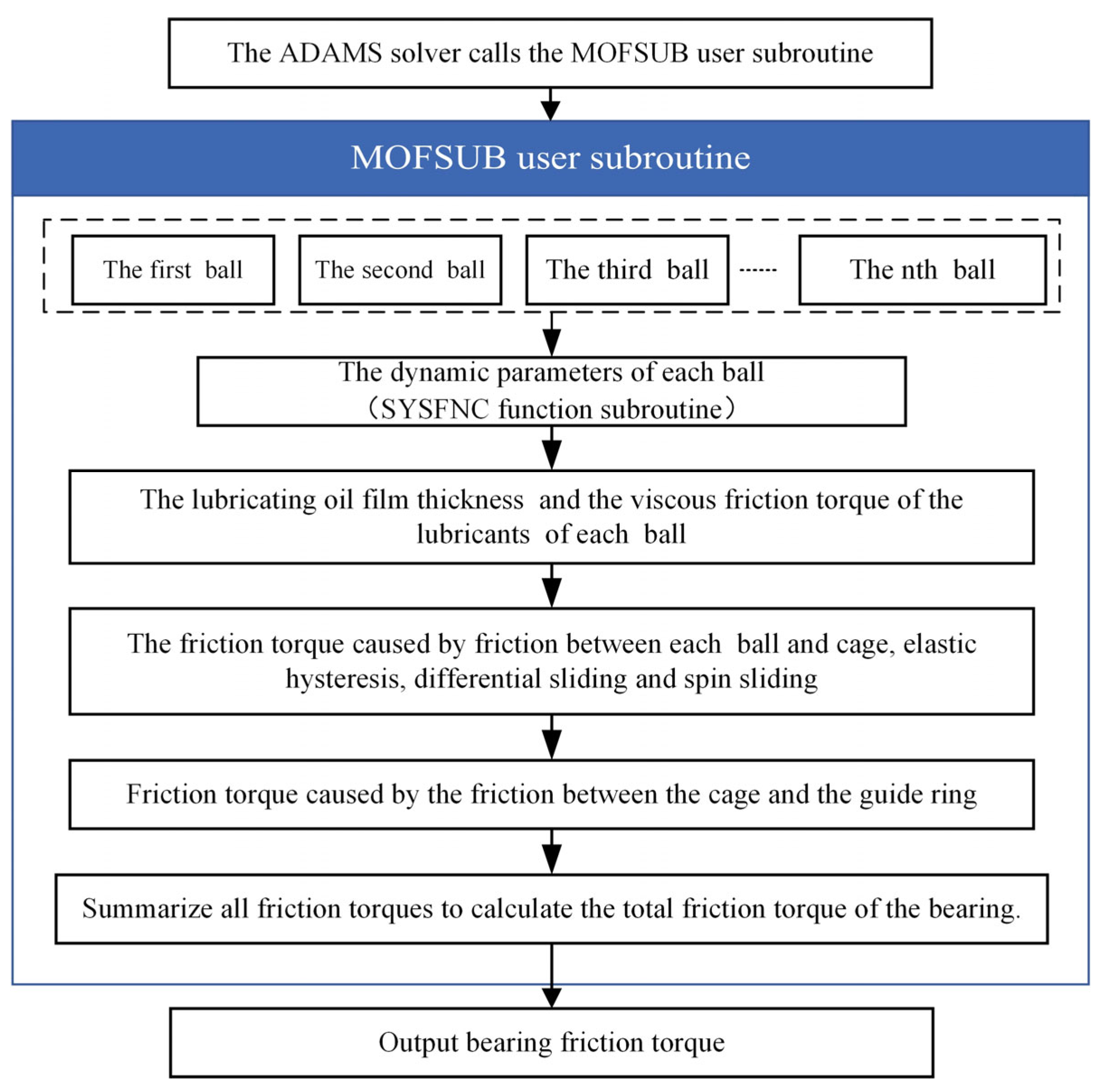
The bearing friction torque is calculated using the custom MOFSUB user subroutine using MSC ADAMS 2020 software. The SYSFNC functional subroutine can realize the acquisition, preservation, and transmission of system information such as displacement, speed, and force. It is a special subroutine with specific functions provided by ADAMS for users that can be called directly without writing. The MOFSUB user subroutine uses the SYSFNC functional subroutine to extract the dynamic parameters of each ball and calculate the friction torque of a single ball, then output the total friction torque of the bearing. The calculation process for the MOFSUB user subroutine is shown in Figure 5.
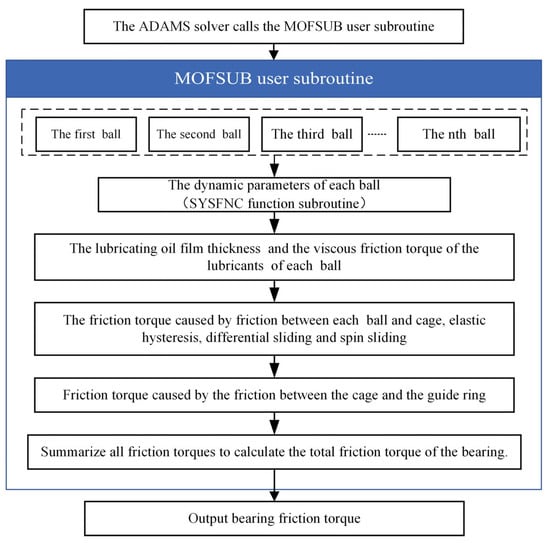
Figure 5.
Program block diagram for calculating bearing friction torque by MOFSUB user subroutine.
The calculation formula for the overall heat generation of the bearing [24] is shown in Equation (13):
where H is the overall heat generation of the bearing, W; n is the bearing speed, r/min; M is the friction torque of the bearing, N∙m.
2.3. Modified Transient Thermal Network Equation of Double-Piece Inner Ring Ball Bearing
In this section, the heat exchange between the oil tank and tubing is considered, and a thermal network heat transfer equation considering the circulating flow of lubricant is established. Considering the uneven distribution of lubricant in the bearing cavity, the lubricant penetration rate was defined to modify the thermal network equations, and the modified transient thermal network equation of the double-piece inner ring ball bearing was established. A calculation formula for the lubricant penetration rate was proposed based on the simulation of the bearing flow field.
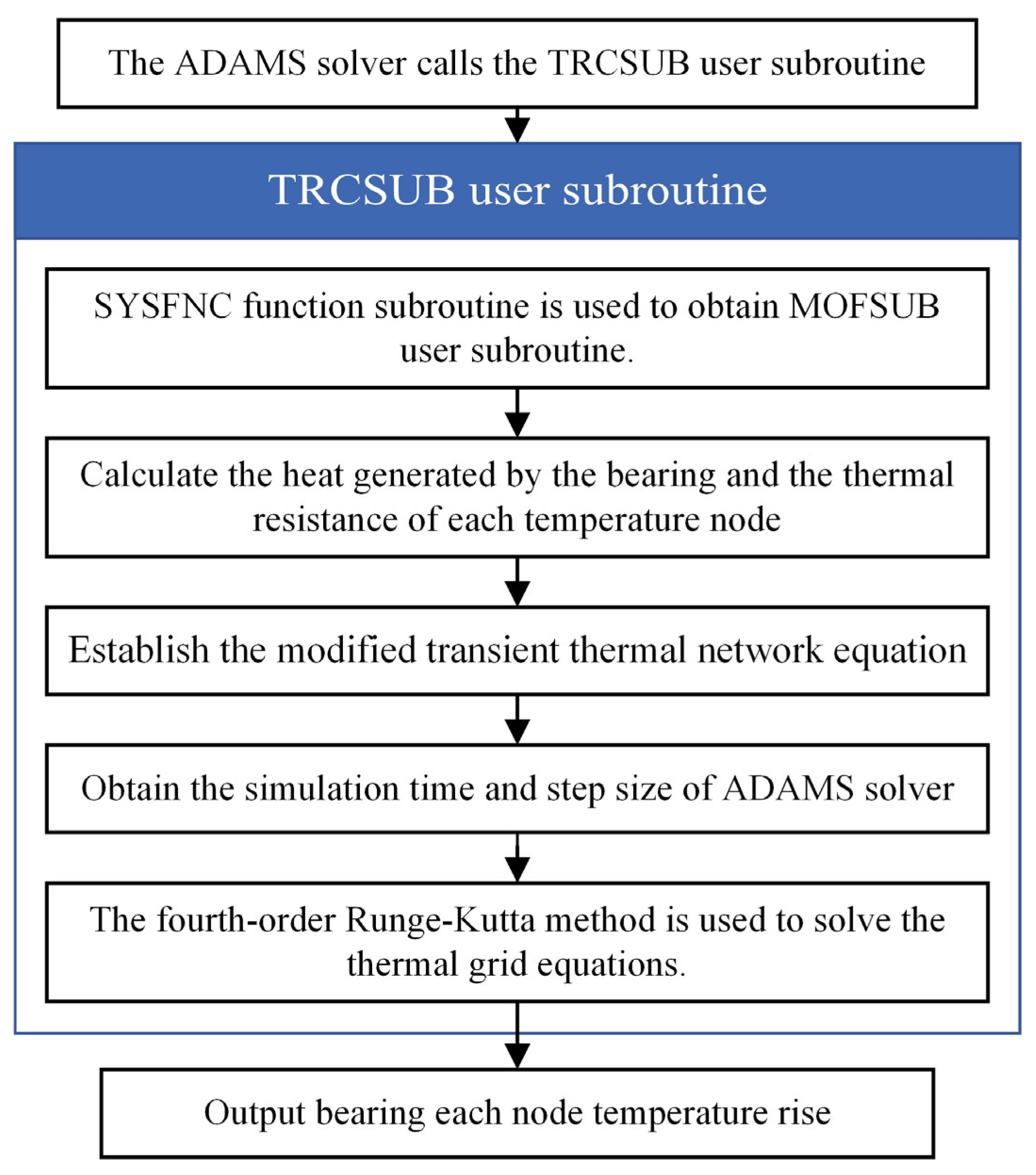
In ADAMS software, the establishment and solution of the modified transient thermal network equation were realized by writing the TRCSUB user subroutine, and the program block diagram is shown in Figure 6. The TRCSUB user subroutine uses the SYSFNC functional subroutine to extract the friction torque calculated by the MOFSUB user subroutine in Section 2.2 and calculate the heat of the bearing. After establishing the thermal network equation, the fourth-order Runge–Kutta [25] method is used to solve the differential equations. Finally, the temperature rise for each node of the bearing is output.
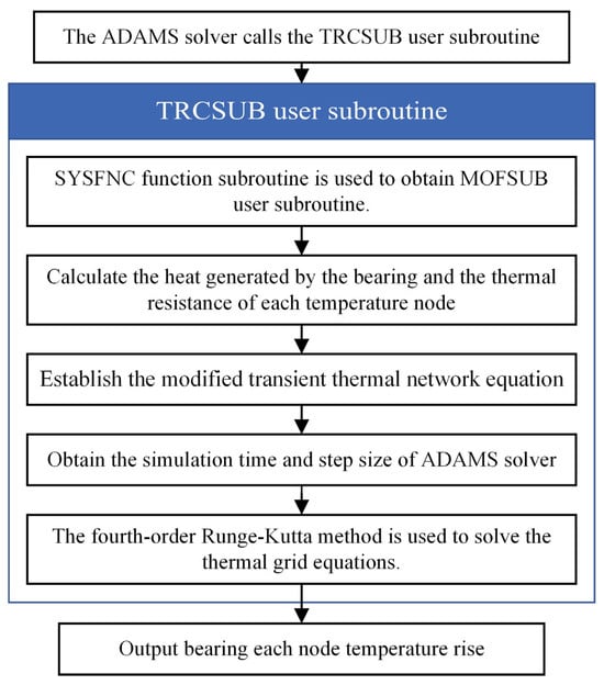
Figure 6.
TRCSUB user subroutine to calculate the bearing temperature rise torque program block diagram.
2.3.1. Heat Transfer Resistance Calculation of Bearing
- (1)
- Thermal resistance of bearing
The bearing rings and bearing seat are all circular, and the calculation formula of heat conduction thermal resistance is shown in Equation (14):
where R is thermal resistance of circular bearing parts, K/W; λ denotes the thermal conductivity, W/(m·K); B denotes the width of the ring, m; D denotes the outer diameter of the ring, m; and d denotes the inner diameter of the ring, m.
- (2)
- Convective heat transfer resistance between bearing and lubricant
In this model, the convective heat transfer between the lubricant and component is forced convection. The calculation formula of average coefficient of forced convection is shown in Equation (15):
where Rd is the convective heat transfer resistance of the lubricants, K/W; ka is the convective heat transfer coefficient of lubricating oil, W/(m2·K); n is bearing speed, r/min; Dw is ball diameter, m; dm is bearing pitch circle diameter, m; a0 is bearing contact angle, °; λr is the thermal conductivity of the lubricant, W/(m·K); Pr is the Prandtl number of the fluid; ν is the kinematic viscosity of the lubricant, m2/s; cr is the specific heat capacity of the lubricant; and S is the convective heat transfer area, m2. In Equation (16), use ‘+’ when the bearing inner ring rotates and ‘−’ when the outer ring rotates.
- (3)
- Thermal resistance of lubricant outside bearing cavity
The lubricant enters the bearing through the inlet pipeline and returns to the oil tank through the outlet pipeline. The lubricant transfers heat to the inner wall of the oil tank and pipeline through convective heat transfer. The inner wall of the oil tank and pipeline transfers heat to the outer wall of the oil tank and pipeline through heat conduction and then transfers heat to the air through thermal convection. The total thermal resistance of the lubricant cooling outside the bearing is the parallel connection between the pipeline heat dissipation thermal resistance and the oil tank heat dissipation thermal resistance [26]. The lubricant cooling heat dissipation thermal resistance calculation formula is shown in Equation (18):
where Rr0 is the total thermal resistance of the lubricant cooling in the oil tank and the pipeline, K/W; Rp is the total thermal resistance of the oil pipeline, K/W; and Rt denotes the total thermal resistance of the tank, K/W.
The pipeline heat dissipation thermal resistance calculation formula is shown in Equation (19):
where λp is the thermal conductivity of the pipe; Lp is the length of the pipe, m; dp is the inner diameter of the pipe, m; Dp is the outer diameter of the pipeline, m; kpr is the convective heat transfer coefficient between the lubricant and inner wall of the pipeline; and kp0 is the convective heat transfer coefficient between the outer wall of the pipeline and air.
The oil tank thermal resistance calculation formula is shown in Equation (20):
where A is the surface area of the oil tank, m2; ktr is the convective heat transfer coefficient between the lubricants and inner wall of the oil tank; and kt0 is the oil tank outer wall and air convection heat transfer coefficient.
2.3.2. Transient Thermal Network Equation Considering Lubricant Circulating Flow
The core theory of the steady-state thermal network is that the heat flow through each node in the system is conserved, the inflow and outflow heats of each node are equal, and the temperature remains stable. To more accurately simulate the change law of temperature rise during the operation of the bearing, this study introduces internal energy variables and establishes a transient thermal network method temperature field calculation equation. The heat inflow and outflow of each node of the bearing are not equal, and the excess heat is transformed into the internal energy of the node, which manifests as the temperature change in the node. The basic formula is shown in Equation (21):
where φ is the heat flow into the node, ρ is the node density, c is the specific heat capacity, V is the effective volume of the node, and dT/dt is the rate of temperature increase at the node.
To improve the analysis efficiency and simplify the analysis equation, this study makes the following assumptions: the friction heat is evenly distributed to the ball and the raceway; the temperature of the bearing changes evenly, ignoring the uneven temperature distribution owing to structural differences. In this case, the temperature node of each part can be set at any position inside it.
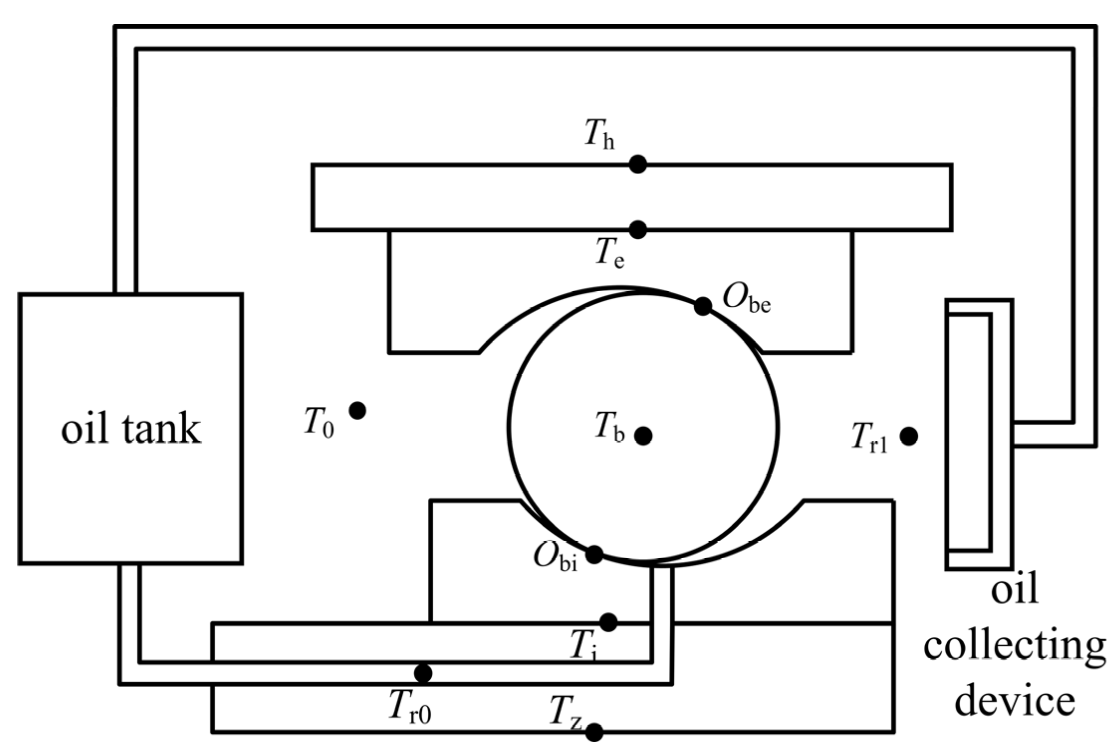
According to the above assumptions, the heat transfer nodes of the double-piece inner ring ball bearing are divided, as shown in Figure 7. When dividing the nodes, the recycling of lubricant in the entire lubrication system was considered, and the oil tank was included in the thermal network to participate in the calculation. In the diagram, T0 is the ambient temperature, Th is the bearing seat temperature, Tz is the spindle temperature, Ti is the bearing inner ring temperature, Te is the outer ring temperature, Tb is the ball temperature, Tr0 is the oil inlet temperature, Tr1 is the oil outlet temperature, and Obi and Obe are the contact points between the ball and the bearing rings.

Figure 7.
Heat transfer node division diagram of double-piece inner ring ball bearing.
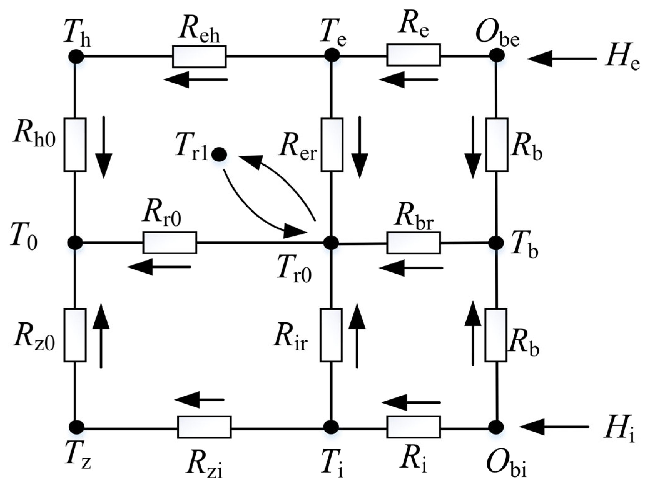
A transient thermal network heat transfer model of a double-piece inner ring ball bearing was established according to the schematic diagram of the heat transfer node division of the bearing, as shown in Figure 8. In this figure, the arrows represent the direction of heat transfer, Hi and He are the heat generated. The heat transfer from the Te, Tb, and Ti nodes to the Tr0 nodes can simulate the heat absorption of the lubricants from the bearing. The heat transfer from the Tr0 to Tr1 node simulates that the lubricant’s temperature rises after absorbing heat from the bearing. The heat transfer from the Tr1 node to the Tr0 node can simulate the mixing of high-temperature lubricant in the oil-gathering device and low-temperature lubricant in the oil tank.
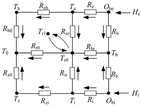
Figure 8.
Schematic diagram of bearing heat transfer network.
The lubricant continuously enters the bearing from the outside world; therefore, the heat absorption temperature is always maintained at the oil inlet temperature, and the volume of lubricant absorbing heat increases continuously with time. When calculating the internal energy change of the lubricant in the bearing cavity, we have to integrate the volume of the lubricant entering the bearing. The basic formula for the lubricant’s internal energy change in the bearing cavity is changed from Equation (21) to Equation (22):
where φTr is the heat absorbed by the lubricant, Tr0 is the oil inlet temperature, Tr1 is the oil outlet temperature, ρr is the lubricant density, cr is the lubricant’s specific heat capacity, and Vr1 is the total volume of lubricant entering the bearing cavity.
The temperature of the lubricant in the oil tank is the oil inlet temperature. When it enters the bearing cavity to absorb heat, it is assumed that it always maintains the oil inlet temperature Tr0 (Tr0 is only kept constant in the bearing cavity). At the moment it flows out of the bearing cavity, the temperature of the lubricating oil suddenly changes to Tr1. When the lubricant flows out of the bearing and enters the oil-collecting device, the oil outlet temperature Tr1 is calculated based on the heat absorbed in the bearing cavity. The lubricating oil always absorbs heat at the temperature of Tr0 in the bearing cavity, and the absorbed heat acts on the lubricating oil at the moment when the lubricating oil flows out of the bearing, resulting in its temperature changing from Tr0 to Tr1. The equilibrium equation of the oil outlet temperature Tr1 node is shown in Equation (23):
where Ti is the bearing inner ring temperature, Te is the outer ring temperature, Tb is the ball temperature, Rbr is the heat transfer resistance between the ball and lubricant, Rer is the heat transfer thermal resistance between the outer ring and lubricant, and Rir is the heat transfer thermal resistance between the bearing inner ring and lubricant.
The heat transfer between the nodes Tr1 and Tr0 is completed by the mixing of lubricating oil at different temperatures. The heat is completely transferred after mixing, and there is no heat transfer resistance between the two nodes. The lubricant flowing out of the bearing cavity enters the oil-collecting device with oil outlet temperature Tr1 and is mixed with the lubricant at a temperature Tr0 in the oil tank, causing the temperature of the lubricant in the oil tank to rise. The oil inlet temperature Tr0 node equilibrium equation is shown in Equation (24):
where Vr0 is the volume of lubricant in the tank, T0 is the ambient temperature, and Rr0 is the total thermal resistance of the lubricant’s heat dissipation outside the bearing.
The ambient temperature T0 is a known constant as the initial condition for solving the equation. The transient heat transfer equation for each node of the other double-piece inner ring ball bearings is shown in Equations (25)–(29). Equations (23)–(29) are the transient thermal network equation of a double-piece inner ring ball bearing.
where ρ, c, and V are the node density, node-specific heat capacity, and node-effective volume, respectively. The distributions of subscripts z, i, b, e, and h represent the bearing seat, outer ring, ball, inner ring, and spindle, respectively. Hi and He are the heat generated, Th is the bearing seat temperature, Tz is the spindle temperature, Rh0 is the heat transfer thermal resistance between the bearing seat and the air, Rz0 is the heat transfer thermal resistance between the spindle and the air, Reh is the heat transfer thermal resistance between the outer ring and the bearing seat, Rzi is the heat transfer thermal resistance between the bearing inner ring and the spindle, Re is the heat transfer thermal resistance between the outer ring and the ball, Ri is the heat transfer thermal resistance between the bearing inner ring and the ball, Rb is the heat transfer resistance of the ball, Rbr is the heat transfer resistance between the ball and the lubricant, Rer is the heat transfer thermal resistance between the outer ring and the lubricant, and Rir is the heat transfer thermal resistance between the bearing inner ring and the lubricant. According to the test bench and bearing structure parameters, the thermal resistance values are shown in Table 1.

Table 1.
Thermal resistance values.
2.3.3. Transient Thermal Network Equation Based on Lubricant Penetration Rate
The uneven distribution of lubricant leads to different amounts of heat absorbed by the lubricant from each part of the bearing. The lubricant enters the bearing cavity from the oil hole under the ring. Some of the lubricant does not reach the outer ring and is directly thrown out of the bearing cavity from the guide clearance. Therefore, according to the volume distribution of the lubricant in the bearing cavity, the lubricant penetration rate is defined as the correction coefficient for correcting the heat absorbed by the oil in the bearing.
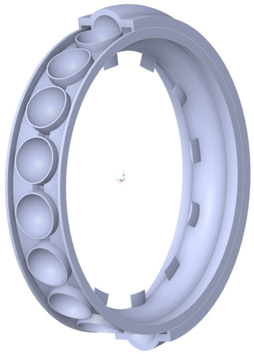
To study the distribution of lubricant in the bearing cavity, Fluent simulation analysis software was used to establish a two-phase flow simulation model of a double-piece inner ring ball bearing based on turbulence model and multiple reference frame method, as shown in Figure 9. The bearing fluid domain is bounded by the annular plane where the center of the ball is located and is divided into two parts: the inner ring fluid domain and the outer ring fluid domain. Only the lubricant that reaches the outer ring fluid domain can absorb heat from the outer ring.
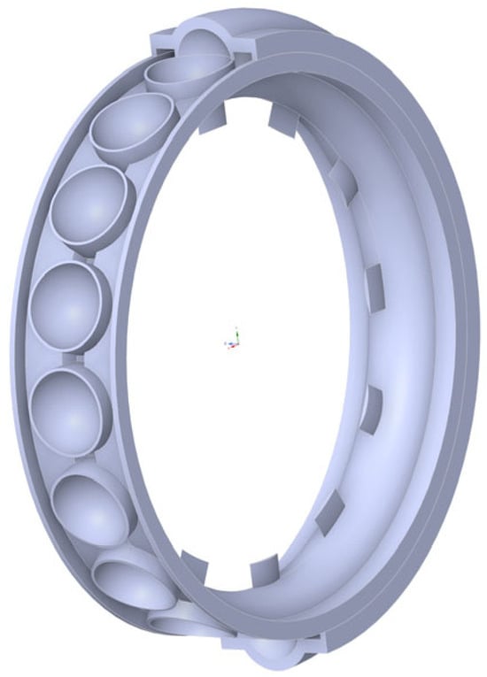
Figure 9.
Three-dimensional modeling display of bearing fluid domain.
Based on the above fluid domain model, Fluent Meshing was used to divide the bearing fluid domain into polyhedral meshes, and a boundary layer was added to the flow field boundary area. The boundary conditions of the flow field simulation were as follows: the inner ring hole was set as the velocity inlet, the boundary on both sides was set as the pressure outlet, and the outlet area was appropriately extended to reduce the influence of the backflow on the flow field simulation. The MRF multiple reference frame method was used to simulate the bearing motion. The flow field in the hole under the ring was a fixed area and a fixed wall. The rotation speeds of the inner ring fluid domain and outer ring fluid domain were the same as the rotation speed of the steel ball. The rotation speeds of the inner ring wall and outer ring wall were set to their actual rotation speeds.
To accurately calculate the heat absorbed by the lubricant from the outer ring, the ratio of the volume of oil that reaches the outer ring to the total volume of oil in the bearing chamber is defined as the penetration rate of the lubricant δ. The lubricant penetration rate is used to describe its ability to reach the outer ring, and the calculation formula is shown in Equation (30):
where δ is the penetration rate of the lubricant; Vri is the lubricant volume in the fluid domain of the inner ring, m3; Vre is the lubricant volume in the fluid domain of the outer ring, m3.
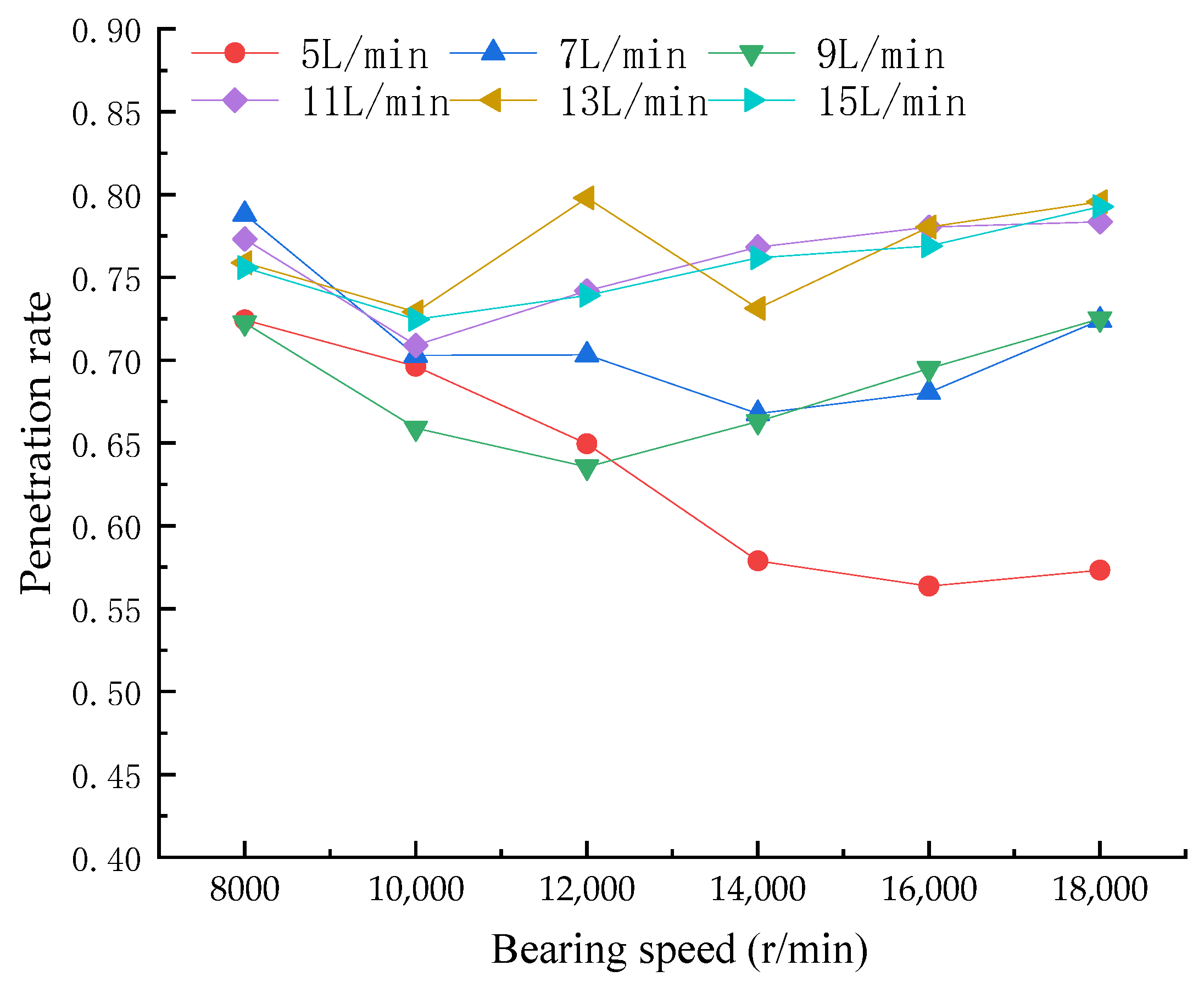
The lubricant penetration rate is closely related to the bearing geometry, bearing speed, and oil supply. In this paper, bearing speeds of 8000 r/min, 10,000 r/min, 12,000 r/min, 14,000 r/min, 16,000 r/min, and 18,000 r/min and oil supplies of 5 L/min, 7 L/min, 9 L/min, 11 L/min, 13 L/min, and 15 L/min were selected for simulation, and the distribution of lubricating oil in bearing cavity under different working conditions were analyzed. According to the simulation results, the penetration rate of the lubricating oil was calculated using Equation (30). The change curve for the lubricating oil penetration rate is shown in Figure 10.
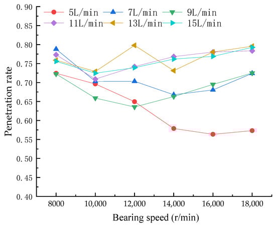
Figure 10.
Change curve of lubricating oil penetration rate with bearing speed at different oil supply rates.
Based on the simulation results, we established a multivariate quadratic polynomial regression equation and used Origin software to determine the undetermined coefficients. For the double-piece inner ring ball bearing used in this paper, the function that conforms to the lubricating oil penetration rate’s change rule is shown in Formula (31).
where A is the ratio of the fluid domain volume of the outer ring to the total volume of the bearing chamber; B, C, D, E, and F are undetermined coefficients; n is the bearing speed (r/min); and m is the lubricant supply of (L/min). According to the structural parameters of the bearing in this study, A was calculated as 0.6193. The undetermined coefficients B, C, D, E, and F were fitted by the simulation results of the bearing flow field. According to the simulation results, the penetration rate of the lubricants is shown in Equation (32):
Not all lubricants can absorb heat from the outer ring of the bearing, so the lubricating oil absorbs less heat from the outer ring of the bearing. The heat absorbed by the lubricant from the outer ring is corrected using the penetration rate. The bearing with a high penetration rate has a better cooling effect on the outer ring. The equilibrium equation of the oil outlet temperature Tr1 is modified from Equation (23) to Equation (33), and the equilibrium equation of the outer ring temperature Te is modified from Equation (28) to Equation (34):
3. Model Validation
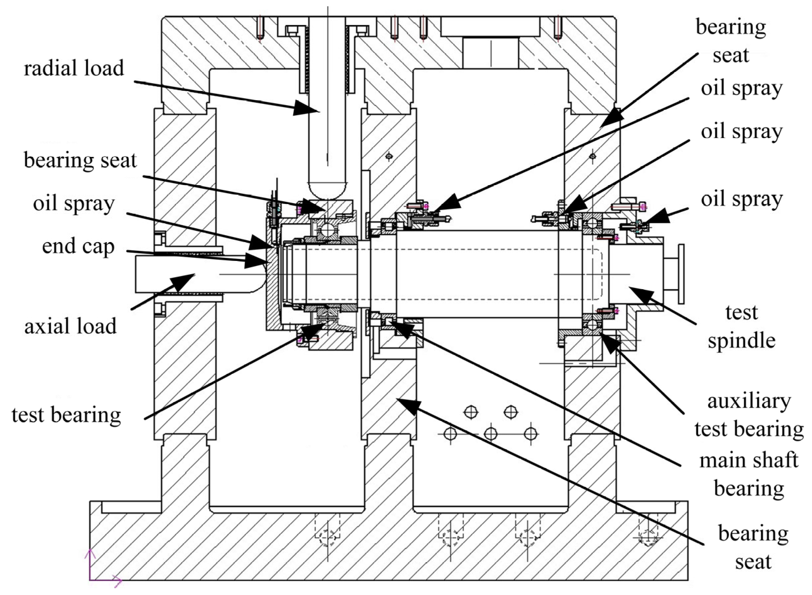
To test the rationality of the transient temperature field model for double-piece inner ring ball bearings, this study built a test bench for double-piece inner ring ball bearings, as shown in Figure 11. The test bench adopted the electric cylinder loading method to apply loads, the size of which was controlled by the control program, and the load was fed back by the force sensor. The maximum speed of the test machine was 20,000 r/min, the axial load loading range was 2000–13,000 N, the radial load loading range was 2000–35,000 N, the maximum oil supply flow rate of the bearing lubrication system was 20 L/min, and the steady-state error was less than 2%, which met the test requirements.
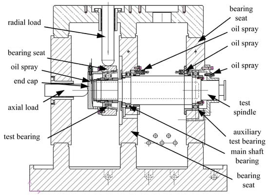
Figure 11.
Principle display of bearing temperature rise test bench.
In this paper, the bearing temperature field model was accompanied by the lubricating oil circulation system outside the bearing cavity, so each bearing in the test bench was equipped with an independent lubrication system and the flow rate was adjusted using an overflow and bypass shunt to meet the flow requirements of the test. The independent lubrication system and accurate flow control make it possible to accurately calculate the heat absorbed by the lubricating oil in the test. During testing, the K-type thermocouple contact temperature sensor collected the outer ring temperature every 5 s, the bearing temperature was regarded as stable when there was no evident fluctuation, and the bearing temperature was recorded. Compared with the traditional bearing temperature rise test bench, this test bench can simulate the lubricant circulation flow process, and the calculation of the heat absorbed by the lubricant is more accurate, thus meeting the verification requirements of the model in this study.
Table 2 is shows experimental bearing parameters. Table 3 lists the experimental bearing materials. This bearing was produced by Luoyang LYC Bearing Co., Ltd. (Luoyang, China). The rotational speed of the experimental bearing was set to 16,000 r/min, the ambient temperature was 26 °C, the oil supply volume was 9.3 L/min, and the lubricant tank volume was 120 L. Table 4 presents the actual loads on the bearings measured using the sensors. These loads are the average load during the operation time of each working condition.
Table 2.
Bearing parameter.
Table 3.
Bearing materials.
Table 4.
Actual loads from double-piece inner ring ball bearing temperature rise tests.
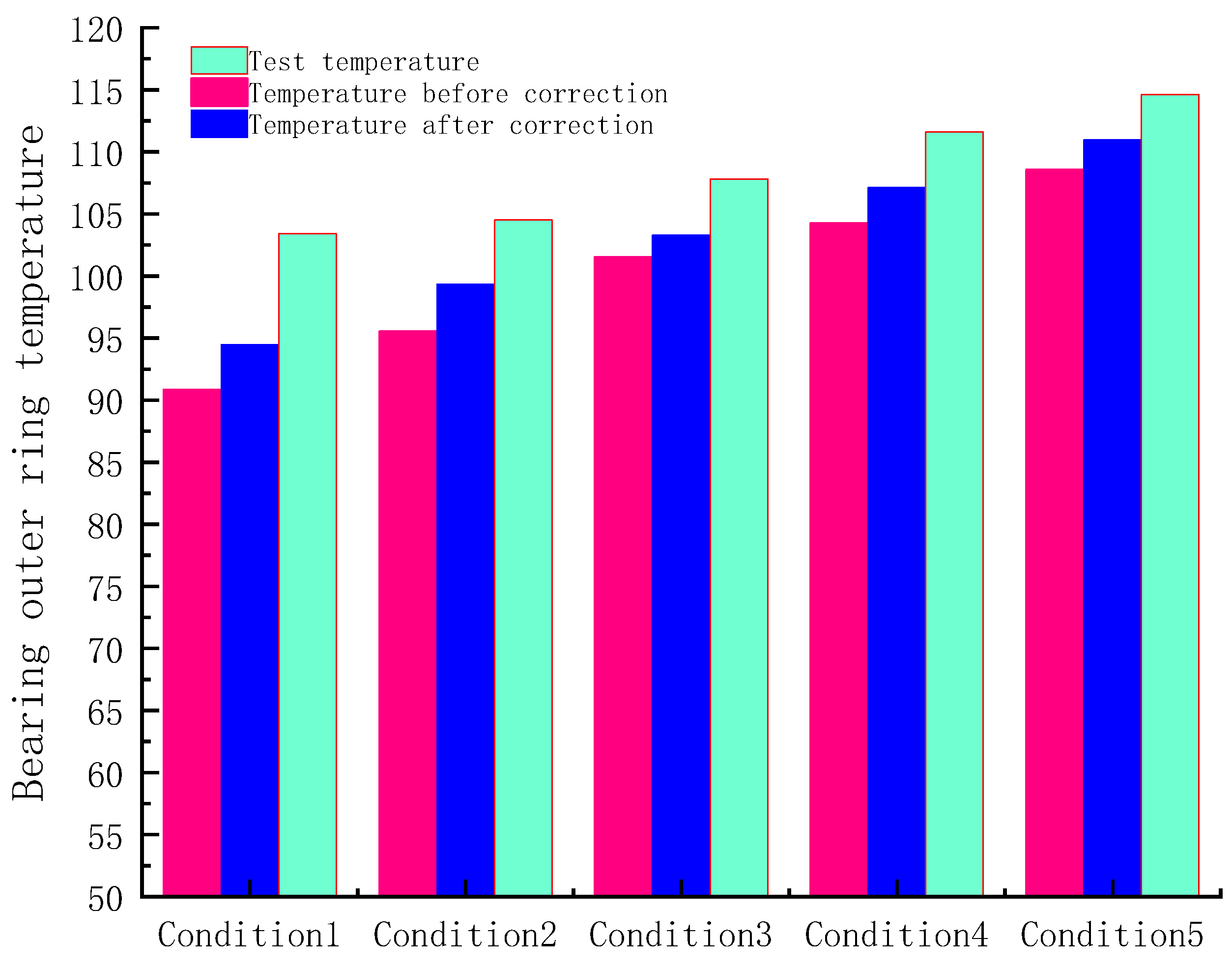
Figure 12 shows the bearing temperature rise test results and the influence of the thermal network method corrected for the lubricant penetration rate on the bearing temperature rise. The test temperature in the figure is the temperature of the bearing outer ring. It can be observed from the figure that the simulation results in this study are consistent with the experimental results. The simulation and experimental results demonstrate the limitation of the traditional thermal network method in calculating the heat absorption of lubricating oil and verify the effectiveness of the thermal network equation modified by the lubricant penetration rate.

Figure 12.
Bearing temperature test and simulation results.
Using of the lubricant penetration to correct the thermal network method can reduce the error between the simulation and test results, and the error is less than 10% after correction. The corrected bearing temperature is higher, which is because the corrected theory explains the phenomenon that the heat dissipation effect of the outer ring of the bearing is worse. The experimental temperature is higher than the simulation temperature; therefore, the simulation model may have a system error. System errors are mainly caused by two factors: First, in this model, when the lubricating oil absorbs heat in the bearing cavity, the oil temperature does not rise immediately but changes abruptly when it flows out of the bearing. This leads to a low lubricating oil temperature in the bearing cavity and removes more heat, resulting in a low bearing temperature in the simulation model. Second, the simulation model ignores the heat generated by the lubricating oil pump. For a certain amount of oil supply, the heat generated by the oil pump can be regarded as a fixed value. At this time, the less heat generated by the bearing, the greater the relative error caused by the heat generated by the oil pump. This also explains the change trend of the largest error in the first working condition and the smallest error in the fifth working condition.
4. Discussion
Past research on bearing thermodynamics shows that the coupling simulation of the dynamics and temperature field or the coupling simulation of the flow field and temperature field is easy to realize, but the coupling effect between the dynamics and flow field is difficult to describe. In this study, the factors influencing the bearing flow field on the temperature field were simplified as the correction coefficient of the lubricant penetration rate. It is relatively simple to add a correction coefficient to the bearing thermal–mechanical coupling simulation model, which realizes the coupling simulation of the bearing dynamics, flow field, and temperature field to a certain extent. Despite the correction coefficient’s preliminary character, the experimental results showed that applying it to the lubricating oil penetration rate can reduce the error in the simulation.
Based on this study, two research ideas could further improve the accuracy of the model. The first is to improve the lubricating oil penetration rate’s calculation accuracy. In this study, the definition of the lubricating oil penetration rate was rough, and the division of the bearing fluid area could be more detailed. This study only discusses the influence of bearing speed and oil supply on the penetration rate of lubricating oil. In the future, we can increase research on factors such as the guide clearance of the cage and number of balls. The second is a more scientific use of the lubricating oil penetration rate correction. In this study, the thermal network equation was modified from the perspective of the heat absorption of lubricating oil; however, in essence, the penetration rate of lubricating oil affects the heat transfer thermal resistance between the bearing and lubricating oil. It is more meaningful to determine the correlation between the bearing flow field and the convective heat transfer thermal resistance of the lubricating oil.
5. Conclusions
In this study, based on the bearing dynamics, two-phase flow field, and modified transient thermal network heat transfer equation, the thermal–mechanical coupling transient temperature field simulation model of a double-piece inner ring ball bearing was constructed, and a temperature rise test was carried out to prove the rationality of the bearing temperature field simulation model. This model has the following innovations:
- (1)
- Theoretical advancement
- a.
- This model considers the heat exchange of the lubricant circulating outside the bearing chamber and can simulate the temperature change during lubricant circulation. The oil inlet temperature is affected by the overall bearing temperature, which solves the problem of ignoring the change in oil inlet temperature in the traditional temperature-field model.
- b.
- In this model, the lubricant temperature node in the oil tank is added to the traditional thermal network method, and the lubricant penetration rate is defined as the correction coefficient to modify the thermal network equation; thus, the modified transient thermal network equation of the double-piece inner ring ball bearing is established.
- (2)
- Methodological paradigm shift
In this study, the influence factors of the bearing flow field on the temperature field were simplified as a correction coefficient for the lubricating oil penetration rate. The correction coefficient was introduced into the bearing thermal–mechanical coupling simulation model, and coupling simulations of the bearing dynamics, flow field, and temperature field were realized using ADAMS secondary development. This provides a feasible scheme for the multifield coupling simulation of bearings.
- (3)
- Practical application
The model is mainly used for the thermodynamic study of double-piece inner ring ball bearings, providing a simulation basis for the design of bearings and their lubrication systems, particularly the lubricant circulation system outside the bearing cavity.
Future research should focus on considering more influencing factors and determining more accurate boundary conditions to improve the robustness of the model under different working conditions.
Author Contributions
Conceptualization, Y.X. and F.M.; methodology, Y.Y. and F.M.; validation, F.M.; resources, Y.X., Y.Y. and H.C.; writing—original draft, F.M.; writing—review and editing, Y.Y.; supervision, Y.X. and H.C.; project administration, Y.Y., Y.X. and H.C. All authors have read and agreed to the published version of the manuscript.
Funding
This research was funded by the Special Project of the Ministry of Industry and Information Technology (Approval No. TC220H05V), the Henan Province Science and Technology Research Project (Approval No. 242102220051), and the Key Scientific Research Projects of Universities in Henan Province (Approval No. 25CY007).
Data Availability Statement
The data used to support the findings of this study are included within the article.
Conflicts of Interest
Authors Yujun Xue and Yongjian Yu were employed by Henan Collaborative Innovation Center for High-End Bearings. The remaining authors declare that the research was conducted in the absence of any commercial or financial relationships that could be construed as a potential conflict of interest.
Nomenclature
| A | oil tank surface area | m2 |
| a0 | bearing contact angle | ° |
| B | ring width | m |
| c | specific heat capacity | J/(kg·°C) |
| cr | lubricant specific heat capacity | J/(kg·°C) |
| cmax | maximum damping coefficient | N/(m/s) |
| D | ring outer diameter | m |
| Dp | pipeline outer diameter | m |
| Dw | ball diameter | m |
| d | ring inner diameter | m |
| dm | bearing pitch circle diameter | m |
| dp | pipe inner diameter | m |
| E | comprehensive elastic modulus of ball surface and raceway | Pa |
| e | Euler constant | Dimensionless |
| e1 | collision force index | Dimensionless |
| ep | ellipticity | Dimensionless |
| F | tangential friction force | N |
| G | dimensionless material parameter | Dimensionless |
| H | overall bearing heat generation | W |
| Hi | inner heat generated | W |
| He | outer heat generated | W |
| hmin | oil film thickness | m |
| K | comprehensive contact stiffness | N/m |
| Kl | Hertz contact stiffness | N/m |
| Kw | oil film stiffness | N/m |
| ka | lubricating oil convective heat transfer coefficient | W/(m2·K) |
| kpr | convective heat transfer coefficient between lubricant and pipeline inner wall | W/(m2·K) |
| kp0 | convective heat transfer coefficient between pipeline outer wall and air | W/(m2·K) |
| ktr | convective heat transfer coefficient between lubricant and oil tank inner wall | W/(m2·K) |
| kt0 | oil tank outer wall and air convection heat transfer coefficient | W/(m2·K) |
| Lp | pipe length | m |
| m | lubricant oil supply | L/min |
| M | bearing friction torque | N∙m |
| n | bearing speed | r/min |
| Pr | fluid Prandtl number | Dimensionless |
| Q | normal contact force | N |
| Qa | load on the convex peak of the contact area | N |
| R | circular bearing part thermal resistance | K/W |
| Rb | ball heat transfer resistance | K/W |
| Rbr | heat transfer resistance between ball and lubricant | K/W |
| Rd | lubricant convective heat transfer resistance | K/W |
| Re | heat transfer thermal resistance between outer ring and ball | K/W |
| Reh | heat transfer thermal resistance between outer ring and bearing seat | K/W |
| Rer | heat transfer thermal resistance between outer ring and lubricant | K/W |
| Rg | equivalent radius of curvature in the long axis direction of the contact area | m |
| Rh0 | heat transfer thermal resistance between the bearing seat and the air | K/W |
| Ri | heat transfer thermal resistance between the bearing inner ring and the ball | K/W |
| Rir | heat transfer thermal resistance between the bearing inner ring and the lubricants | K/W |
| Rr0 | total thermal resistance of the lubricant cooling in the oil tank and the pipeline | K/W |
| Rp | oil pipeline total thermal resistance | K/W |
| Rt | tank total thermal resistance | K/W |
| Rr0 | total thermal resistance of lubricant heat dissipation outside the bearing. | K/W |
| Rz0 | heat transfer thermal resistance between the spindle and the air | K/W |
| Rzi | heat transfer thermal resistance between the bearing inner ring and the spindle | K/W |
| S | convective heat transfer area | m2 |
| T0 | ambient temperature | °C |
| Th | bearing seat temperature | °C |
| Te | outer ring temperature | °C |
| Tb | ball temperature | °C |
| Ti | bearing inner ring temperature | °C |
| Tz | spindle temperature | °C |
| Tr0 | oil inlet temperature | °C |
| Tr1 | oil outlet temperature | °C |
| U | dimensionless velocity parameter | Dimensionless |
| V | volume | m3 |
| Vr0 | volume of lubricant in the tank | m3 |
| Vr1 | total volume of the lubricant entering the bearing cavity | m3 |
| Vri | lubricant volume in the fluid domain of the inner ring | m3 |
| Vre | lubricant volume in the fluid domain of the outer ring | m3 |
| x | mutual penetration depth of two objects | m |
| ΔI | variation in the actual distance of the surface of the two collision parts caused by the thermal effect | m |
| ΔT | temperature variation | °C |
| δ | lubricant penetration rate | Dimensionless |
| η | lubricant dynamic viscosity | Pa∙s |
| λ | thermal conductivity | W/(m·K) |
| λr | lubricant thermal conductivity | W/(m·K) |
| λp | pipe thermal conductivity | W/(m·K) |
| μ | lubricant film drag coefficient | Dimensionless |
| μa | contact area peak friction coefficient | Dimensionless |
| ν | lubricant kinematic viscosity | m2/s |
| ρ | density | Kg/m3 |
| ρr | lubricant density | Kg/m3 |
| σi | inner ring thermal expansion coefficient | °C−1 |
| σe | outer ring thermal expansion coefficient | °C−1 |
| σb | ball thermal expansion coefficient | °C−1 |
| τ | film thickness ratio | Dimensionless |
| φ | heat flow into the node | W |
| φTr | heat absorbed by the lubricant | W |
References
- Palmgren, A. Ball and Roller Bearing Engineering; SKF Industries Inc.: Philadelphia, PA, USA, 1959. [Google Scholar]
- Harris, T.A.; Kotzalas, M.N. Advanced Concepts of Bearing Technology: Rolling Bearing Analysis; CRC Press, Taylor Francis Group: New York, NY, USA, 2006. [Google Scholar]
- Kim, K.S.; Lee, D.W.; Lee, S.M.; Lee, S.J.; Hwang, J.H. A numerical approach to determine the frictional torque and temperature of an angular contact ball bearing in a spindle system. Int. J. Precis. Eng. Manuf. 2015, 16, 135–142. [Google Scholar]
- Wu, W.; Hu, C.; Hu, J.; Yuan, S. Jet cooling for rolling bearings: Flow visualization and temperature distribution. Appl. Therm. Eng. 2016, 105, 217–224. [Google Scholar]
- Wu, W.; Hu, J.; Yuan, S.; Hu, C. Numerical and experimental investigation of the stratified air-oil flow inside ball bearings. Int. J. Heat Mass Transf. 2016, 103, 619–626. [Google Scholar]
- Li, Y.; Yang, Z.; Chen, F.; Zhao, J. Effect of air inlet flow rate on flow uniformity under oil-air lubrication. Ind. Lubr. Tribol. 2018, 70, 282–289. [Google Scholar]
- Gao, W.; Nelias, D.; Li, K.; Liu, Z.; Lyu, Y. A multiphase computational study of oil distribution inside roller bearings with under-race lubrication. Tribol. Int. 2019, 140, 105862. [Google Scholar]
- Li, M.; Wang, Y.; Chen, W.; Zhu, R. Temperature rise characteristics for angular-contact ball bearings with oil-air lubrication based on fluid-solid conjugate heat transfer. Adv. Mech. Eng. 2021, 13, 1687814021990927. [Google Scholar]
- Bao, H.; Hou, X.; Tang, X.; Lu, F. Analysis of temperature field and convection heat transfer of oil-air two-phase flow for ball bearing with under-race lubrication. Ind. Lubr. Tribol. 2021, 73, 817–821. [Google Scholar]
- Dong, Y.; Ma, Y.; Qiu, M.; Chen, F.; He, K. Analysis and experimental research of transient temperature rise characteristics of high-speed cylindrical roller bearing. Sci. Rep. 2024, 14, 711. [Google Scholar]
- Xu, K.; Hu, H.; Guo, N.; Ma, X.; Li, X. Research on Temperature Rise Characteristics Prediction of Main Shaft Dual-Rotor Rolling Bearings in Aircraft Engines. Lubricants 2024, 12, 210. [Google Scholar] [CrossRef]
- Winer, W.O.; Bair, S.; Gecim, B. Thermal resistance of a tapered roller bearing. ASLE Trans. 1986, 29, 539–547. [Google Scholar]
- Bossmanns, B.; Tu, J.F. A thermal model for high speed motorized spindles. Int. J. Mach. Tools Manuf. 1999, 39, 1345–1366. [Google Scholar]
- Cole, K.D.; Tarawneh, C.M.; Fuentes, A.A.; Wilson, B.M.; Navarro, L. Thermal models of railroad wheels and bearings. Int. J. Heat Mass Transf. 2010, 53, 1636–1645. [Google Scholar]
- Neurouth, A.; Changenet, C.; Ville, F.; Arnaudon, A. Thermal modeling of a grease lubricated thrust ball bearing. Proc. Inst. Mech. Eng. Part J J. Eng. Tribol. 2014, 228, 1266–1275. [Google Scholar]
- Yan, K.; Hong, J.; Zhang, J.; Mi, W.; Wu, W. Thermal-deformation coupling in thermal network for transient analysis of spindle-bearing system. Int. J. Therm. Sci. 2016, 104, 1–12. [Google Scholar]
- Zheng, D.; Chen, W. Thermal performances on angular contact ball bearing of high-speed spindle considering structural constraints under oil-air lubrication. Tribol. Int. 2017, 109, 593–601. [Google Scholar]
- Zheng, D.X.; Chen, W.F. Effect of structure and assembly constraints on temperature of high-speed angular contact ball bearings with thermal network method. Mech. Syst. Signal Process. 2020, 145, 106929. [Google Scholar]
- Brossier, P.; Niel, D.; Changenet, C.; Ville, F.; Belmonte, J. Experimental and numerical investigations on rolling element bearing thermal behaviour. Proc. Inst. Mech. Eng. Part J J. Eng. Tribol. 2021, 235, 842–853. [Google Scholar]
- Lei, J.; Su, B.; Zhang, S.; Yang, H.; Cui, Y. Dynamics-based thermal analysis of high-speed angular contact ball bearings with under-race lubrication. Machines 2023, 11, 691. [Google Scholar] [CrossRef]
- Tao, X.; Yuli, C.; Tao, C.; Shoujing, Z.; Qing, Z. A Thermal Preload Analysis Method of Angular Ball Bearing Considering Temperature Rise. Int. J. Precis. Eng. Manuf. 2024, 25, 2625–2637. [Google Scholar]
- Liu, Y.; Chen, Z.; Zhai, W.; Lei, Y. Investigation on skidding behavior of a lubricated rolling bearing with fluid–solid-heat coupling effect. Mech. Syst. Signal Process. 2024, 206, 110922. [Google Scholar]
- Yang, X.Q. Contact Mechanics Theory and Rolling Bearing Design Analysis; Huazhong University of Science & Technology Press: Wuhan, China, 2018. [Google Scholar]
- Deng, S.E.; Jia, Q.; Xue, J. Rolling Bearing Design Principle; China Standard Press: Beijing, China, 2014; p. 132. [Google Scholar]
- Tan, D.; Chen, Z. On a general formula of fourth order Runge-Kutta method. J. Math. Sci. Math. Educ. 2012, 7, 1–10. [Google Scholar]
- Latif, M. Jiji. In Heat Convection, 2nd ed.; Springer: Berlin/Heidelberg, Germany, 2009. [Google Scholar]
Disclaimer/Publisher’s Note: The statements, opinions and data contained in all publications are solely those of the individual author(s) and contributor(s) and not of MDPI and/or the editor(s). MDPI and/or the editor(s) disclaim responsibility for any injury to people or property resulting from any ideas, methods, instructions or products referred to in the content. |
© 2025 by the authors. Licensee MDPI, Basel, Switzerland. This article is an open access article distributed under the terms and conditions of the Creative Commons Attribution (CC BY) license (https://creativecommons.org/licenses/by/4.0/).