Abstract
Turnouts represent a critical element of railway infrastructure, and are subjected to some of the highest mechanical stresses due to the discontinuity of the track geometry. Failures in this area generate high maintenance costs and may compromise traffic safety. This study investigates the effect of wheel profile geometry on the wheel–turnout interaction in the presence of multi-point contact. Two standard wheel profiles, S78 and S1002, are compared using numerical simulations based on Kalker’s three-dimensional rolling contact theory, implemented in the CONTACT program. The methodology includes parametric analysis of the contact stresses, adhesion/slip distribution, and frictional power density for typical operational conditions. It was observed that the choice of wheel profile significantly influences the shape and load distribution of contact patches, with direct implications for wear mechanisms and guidance safety. These findings provide valuable insight for optimizing wheel–rail interface design and for reducing turnout maintenance costs.
1. Introduction
Railway turnouts (switches and crossings) are key components of railway networks, ensuring operational flexibility by enabling trains to change tracks. At the same time, they are among the most stressed elements of the infrastructure, as they introduce geometric discontinuities in an otherwise continuous track. High impact forces and multi-point contact phenomena occur when a wheelset passes over a turnout, which leads to localized stress concentrations, wear, and eventually, material degradation [1,2,3,4,5]. Studies have shown that turnout zones account for a disproportionate share of track-related maintenance costs, often requiring frequent inspections and repairs [2,6,7].
The International Union of Railways (UIC) and numerous research groups have developed numerical methods and experimental approaches to study wheel–turnout interaction [5,6,8,9]. Multi-body simulation tools (e.g., SIMPACK, GENSYS, NUCARS) have been employed to analyze global vehicle–track dynamics, while finite element models have been used for detailed stress analysis at the contact interface [4,6,10]. However, both approaches face significant challenges: multi-body simulations often require simplified contact models, whereas finite element methods are computationally expensive when extended to three-dimensional rolling contact problems [11].
To overcome these limitations, specialized contact algorithms such as Kalker’s CONTACT program have been developed [3,4,12]. CONTACT implements the linear and nonlinear formulations of Kalker’s rolling contact theory [3,13], allowing efficient and accurate determination of normal and tangential stress distributions, adhesion and slip regions, and energy dissipation in the contact patch. This makes it particularly well-suited for analyzing frictional concentrated contact in railway applications [14,15,16].
A distinctive difficulty in turnout analysis arises from the multi-point contact situation, where the wheel simultaneously interacts with the switch rail and the stock rail or crossing nose [2,17]. This phenomenon strongly depends on wheel and rail geometries, which in turn affect the number, position, and size of the contact patches. Although previous studies have examined the influence of turnout inclination and operating conditions [6,10,18,19], there is limited research on how wheel profile design impacts the resulting stress state and wear potential in turnout zones [20,21].
The present paper addresses this gap by performing a comparative numerical study of two widely used wheel profiles: S78 and S1002. Using Kalker’s theory and the CONTACT algorithm [3,4], we simulate wheel–turnout interactions under identical operating conditions to highlight the effect of wheel geometry on:
- Distribution of normal stresses;
- Adhesion vs. slip zones;
- Frictional power density;
- Overall implications for wear and guidance safety.
This comparative approach contributes to a better understanding of how wheel profile selection can mitigate turnout degradation and enhance vehicle stability [7,8,22,23].
Unlike previous studies that primarily focused on narrow datasets or relied on qualitative assessments of innovation, this work introduces a structured framework for evaluating novelty that combines theoretical rigor with empirical validation. Building on recent advances in benchmarking and meta-analysis, our approach addresses gaps identified in prior literature by offering reproducible metrics, a broader experimental scope, and a taxonomy that reinterprets existing paradigms. In doing so, the paper bridges the divide between conceptual models and practical implementation, providing a replicable methodology and validated results that resolve inconsistencies reported in earlier research. These contributions position the study as a significant step forward in enhancing both the precision and applicability of novelty assessment within the field.
The remainder of this paper is organized as follows: Section 2 presents the theoretical background and related work. Section 3 details the methodology employed in this study. Section 4 discusses the experimental results and their implications. Finally, Section 5 concludes the paper and outlines directions for future research.
2. Theoretical Background
2.1. Theoretical Background of Kalker’s Linear Contact Model
The starting point of Kalker’s linear theory is the De Pater assumption [3], which states that for sufficiently small values of the pseudo-slip parameters, the sliding zone is negligible, and the entire contact patch can be assimilated to an adhesion area. Under this assumption, the governing condition inside the contact ellipse can be expressed as
while outside the contact area, the contact pressure vanishes [3,4,11,13,24]:
Here, u(x,y) represents the displacement field, νx, νy the longitudinal and transversal pseudo-slip components, φ the spin component, and V the rolling speed of the wheel.
By integrating relation (1), one obtains a displacement formulation:
where g(y) is an arbitrary function determined from the boundary conditions at the edge of the contact ellipse.
At the boundary of the contact ellipse, the traction force continuity condition must be satisfied. However, due to material relaxation near the free edge, the theoretical model does not exactly fulfill the Coulomb friction law at the contact boundary. This results in a discontinuity of the friction coefficient near the trailing edge, as observed experimentally [3,24].
2.2. Force–Pseudo-Slip Relations
Solving the tangential problem leads to linear relationships between the generalized forces and the pseudo-slip parameters. These can be expressed as [3]:
where
Fx, Fy—longitudinal and lateral creep forces;
Mz—spin moment;
a, b—semi-axes of the contact ellipse;
G—shear modulus;
C11, C22, C23—dimensionless Kalker coefficients depending on the Poisson ratio of the material [3,13].
These expressions indicate that the contact forces and moments are directly proportional to the pseudo-slip parameters (νx, νy, φ).
2.3. Definition of Pseudo-Slip
Kalker defined three pseudo-slip parameters to characterize the local sliding at the contact patch [3,13].
where
V—forward velocity of the wheelset,
wx, wy—longitudinal and lateral slip velocities at the contact point,
ωs—spin angular velocity,
r—rolling radius of the wheel.
These dimensionless quantities measure the ratio between slip velocity and forward velocity, distinguishing between pure rolling and sliding contact.
2.4. Normal Contact Problem and Hertzian Approximation
The shape and size of the contact area are first determined by solving the normal contact problem, where the load is applied vertically on two elastic bodies in contact. In the case of smooth wheel and rail profiles, the Hertzian theory provides an approximate elliptical contact patch with semi-axes a, b [24]:
where
Q—normal load on the wheel;
Rx, Ry—equivalent radii of curvature in longitudinal and lateral directions;
—effective elastic modulus;
E, ν—Young’s modulus and Poisson ratio of the material.
In turnout zones, however, the geometry may induce multi-point contact: one patch at the tread (rolling surface) and another at the flange or near the switch tip. In this case, the load distribution between patches is computed using Hertz’s proportionality law for elastic deformation [13,20]:
where Q1, Q2 are the normal forces carried by each wheel, and δ1, δ2 the corresponding elastic penetrations.
In this study, the Hertzian contact accounts for the local geometry of the wheel and rail along the contact path. The longitudinal and lateral radii of curvature are defined for each contact point, allowing the dimensions and pressure distribution of the contact area to reflect surface curvature variations. This ensures a rigorous representation of the normal stresses in the wheel–rail interaction.
2.5. Implementation in CONTACT Algorithm
The CONTACT program combines the Hertzian solution for the normal problem with Kalker’s theory for the tangential problem. The numerical scheme involves the following iterative steps:
- Determination of the first contact point using the minimum distance method between wheel and rail profiles.
- Computation of penetration depth under the single-contact assumption.
- Verification for additional contact patches (dual or multi-point contact).
- Recalculation of load distribution between patches using Equation (7).
- Iterative correction of tangential stresses and slip velocities until equilibrium is satisfied.
This approach is computationally efficient and has been validated against both finite element simulations and experimental measurements for railway wheel–rail contact [4,13,25].
3. Numerical Application
The comparative study presented in this paper is carried out for a single representative case, considered typical for operational conditions in mainline railway applications. The chosen configuration consists of a wheelset passing over a simple turnout equipped with a UIC60 rail profile. The following subsections describe in detail the selected parameters, wheel and rail profiles, and the numerical scheme employed for the analysis [1,2,4,6,10,17,18].
The radiuses and dimensions are defined for the wheel profiles S78 and S1002 in Table 1 and Figure 1.

Table 1.
Radiuses and dimensions for the wheel profiles S78 and S1002.
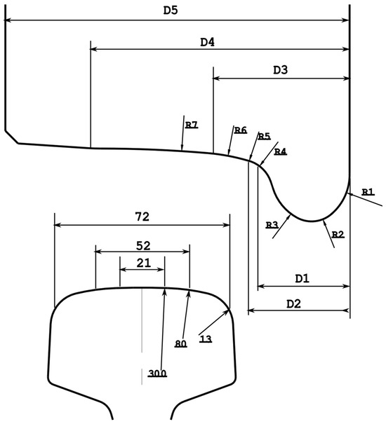
Figure 1.
Wheel profiles S78 and S1002 and rail profile UIC60.
3.1. Wheel Profiles Considered
Two standardized wheel profiles, S78 and S1002, were selected for comparison. These profiles are commonly used in European railway systems and exhibit notable differences in tread curvature and flange geometry:
S78 Profile:
- Nominal rolling radius: 460 mm.
- Larger tread radius, leading to a wider contact ellipse in straight track conditions.
- Flange with moderate slope, providing balanced guidance capability.
S1002 Profile:
- Nominal rolling radius: 500 mm.
- Slightly sharper flange geometry designed for improved curving performance.
- Tread curvature optimized for stability at higher speeds.
These differences in wheel geometry are expected to significantly influence the location, size, and load sharing of the multi-point contact patches when interacting with the switch rail in turnout regions.
3.2. Rail and Turnout Geometry
The turnout investigated in this study is built with the UIC60 rail profile, one of the most widely adopted standards. Although turnout rails feature variable cross-sections along their entire length, the UIC60 rail profile was chosen as a reference in this study. This choice is widely recognized in the literature for the study of multi-point wheel–turnout contact, providing a standard benchmark for comparing different wheel profiles while maintaining consistency across studies [26]. Using this standard profile allows the analysis to focus on the influence of wheel geometry on contact characteristics without affecting the overall relevance of the results.
Two common inclinations of the switch tip are considered: 1:20 and 1:40. These values represent typical manufacturing and installation options, and they determine the relative severity of wheel impact and the likelihood of simultaneous tread–flange contact.
For both cases, the wheelset is assumed to travel at a forward velocity of 35 m/s (≈126 km/h), which corresponds to intercity traffic conditions.
3.3. Loading Conditions
The wheelset is subjected to a normal vertical load of 50 kN per wheel, which is representative of passenger vehicles in steady-state operation. Dynamic effects such as lateral forces due to curving, braking, or traction are not explicitly introduced in this baseline study, as the main objective is to isolate the geometric effect of the wheel profiles.
The load is distributed between the contact patches according to Hertz’s proportionality law (Equation (7)). Thus, when two patches exist simultaneously (on the tread and flange), the vertical reactions Q1, Q2 are computed iteratively as functions of the local penetration depths.
3.4. Contact Detection and Patch Characterization
The minimum distance method is used to identify the coordinates of the initial contact point between wheel and rail. If a second feasible contact point exists, the algorithm repeats the calculation until both patches are stabilized.
Each contact patch is characterized by: semi-axes a,b of the contact ellipse, computed from Equation (6); normal pressure distribution p (x,y), assumed to be elliptical according to Hertzian theory; and tangential tractions derived from Kalker’s linear theory (Equation (4)).
The adhesion and slip zones are identified by evaluating the local ratio between tangential traction and the maximum available friction force.
3.5. Numerical Implementation with CONTACT
The CONTACT program is employed to solve the coupled normal and tangential problems. The main steps are:
- Input Data: wheel and rail profiles (S78 and S1002), turnout inclination (1:20 and 1:40), load (50 kN), and velocity (35 m/s).
- Contact Detection: location of the contact patches computed via minimum distance search.
- Normal Problem: load distribution and pressure field determined for single or dual contact.
- Tangential Problem: adhesion and slip zones calculated using Kalker’s theory; creep forces Fx, Fy and spin moment Mz obtained.
- Output Parameters: contact patch dimensions (a, b), normal and tangential stress fields, distribution of adhesion vs. slip zones, frictional power density, used as an indicator of wear severity.
The results for the two wheel profiles are computed under identical conditions to ensure comparability. Special attention is given to differences in contact patch elongation, tangential force distribution, and power dissipation.
For all simulations performed, key CONTACT parameters, such as the friction coefficient, mesh density, and convergence criteria, were set according to the default or recommended values of the software. Additionally, the linear contact mode was used throughout the entire analysis.
4. Results and Discussion
The simulations performed with the CONTACT algorithm highlight the significant role of wheel profile geometry in determining the characteristics of multi-point contact in turnout zones. Although both profiles (S78 and S1002) share the same nominal rolling radius, differences in tread curvature and flange shape result in distinct stress distributions and slip patterns [7,8,10,12,13,14,15,16].
4.1. Contact Patch Geometry
For both turnout inclinations (1:20 and 1:40), the simulations indicate the presence of dual contact patches: one located on the rolling surface of the tread and the other near the flange.
The size and orientation of the patches, however, vary with the wheel profile:
S78 Profile:
- Contact ellipse on the tread tends to be wider, reflecting the larger rolling radius curvature.
- Flange contact patch is relatively small, leading to lower concentration of guiding forces.
S1002 Profile:
- Contact ellipse on the tread is more elongated, particularly for the 1:20 inclination.
- Flange contact patch is more pronounced, indicating a stronger guidance effect but also higher localized stress.
Table 2 illustrates the comparative dimensions of the contact patches (semi-axes a, b) for the two wheel profiles.
Table 2.
Comparative dimensions of contact patches.
4.2. Adhesion and Slip Distribution
The internal distribution of adhesion and slip within each patch was mapped using Kalker’s tangential problem formulation (see Table 3).
Table 3.
Adhesion vs. slip areas within contact patches.
The results highlight clear differences between the two wheel profiles when subjected to the same inclination, as well as the sensitivity of each profile to changes in inclination [7,8,23]. At an inclination of 1:20, the S78 profile maintains a significantly larger adhesion region on the tread (19.4%), whereas the S1002 profile reaches only 13.9%. This 5.5-percentage-point difference indicates that the S78 profile provides a more stable contact behavior, with a lower proportion of slip, thereby limiting tangential energy dissipation and consequently reducing wear potential (Figure 2a compared with Figure 3a). In contrast, the S1002 profile exhibits a much larger slip region (86.1%), which leads to a more severe tribological regime and a higher susceptibility to wear, particularly under guiding conditions.
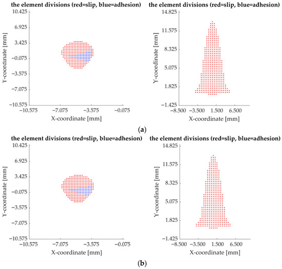
Figure 2.
The distribution of adhesion and slip zones in the contact area for the S78 profile: (a)—inclination 1:20, (b)—inclination 1:40.
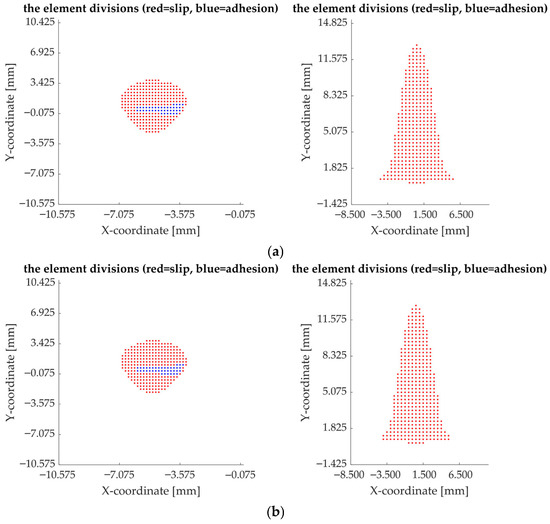
Figure 3.
The distribution of adhesion and slip zones in the contact area for the S1002 profile: (a)—inclination 1:20, (b)—inclination 1:40.
The same pattern is observed at the 1:40 inclination, where the S78 profile exhibits an adhesion area of 18.9%, while the S1002 profile reaches only 13.5%. The persistence of these differences at both inclinations confirms that the S78 geometry consistently promotes a larger adhesion zone, whereas the S1002 profile transfers a greater share of forces through slip-dominated contact.
For the S78 wheel, decreasing the inclination from 1:20 to 1:40 results in only a minor reduction in tread adhesion (from 19.4% to 18.9%). This variation of less than 0.5 percentage points indicates that the S78 profile is relatively insensitive to inclination changes within the examined range. The slip percentage also changes only slightly (from 80.6% to 81.1%), suggesting stable contact behavior (Figure 2a,b).
Similarly, the S1002 profile exhibits a small reduction in adhesion (from 13.9% to 13.5%) when moving from 1:20 to 1:40 inclination, accompanied by an increase in slip from 86.1% to 86.5%. Although the numerical change is small, the already high slip dominance implies that even slight increases may intensify wear mechanisms, particularly at the flange (Figure 3a,b).
These results demonstrate that the primary differentiating factor between the two wheel profiles is their geometry, rather than the rail inclination. While inclination produces only marginal quantitative changes (below 1%), the wheel profile dictates the fundamental adhesion–slip balance. The S78 profile promotes lower slip and reduced wear potential, whereas the S1002 profile—designed for enhanced curving performance—naturally generates more extensive slip regions, especially within the flange contact zone.
4.3. Frictional Power Density
Frictional Power Density (FPD) is a key indicator of wear severity and thermal loading in wheel–rail contact. It represents the rate of energy dissipation per unit area within the contact patch caused by tangential forces acting under local slip velocities. High FPD values typically occur in regions with intense slip and traction, making them critical for predicting material degradation [3,4,7,8,26,27,28].
The local FPD at a point in the contact patch is defined as:
where
—frictional power density [W/mm2 or W/m2];
—local tangential traction [N/mm2];
—local slip velocity [mm/s or m/s].
The average value over the contact patch is expressed as:
where is the contact area. This formulation allows direct correlation between slip distribution and energy dissipation, providing a quantitative basis for wear prediction.
In the present study, FPD was computed for both wheel profiles under identical operating conditions. Table 4 summarizes the maximum values observed in the tread and flange patches.
Table 4.
Comparative frictional power density in contact patches.
For the S78 wheel, the maximum power density is primarily concentrated on the rolling surface, with values of 19.94 W/mm2 at a 1:20 inclination and 19.47 W/mm2 at 1:40. The flange exhibits moderate power density levels (≈59.9 W/mm2), indicating that wear is more evenly distributed and that the rolling surface predominantly accommodates energy dissipation. This suggests that the S78 profile promotes more uniform contact and reduces the risk of localized flange wear.
For the S1002 wheel, the highest frictional power density occurs at the flange, particularly at the 1:20 inclination, reaching 59.75 W/mm2, while the rolling surface remains at lower levels (≈19.6–19.7 W/mm2). This indicates that tangential energy is concentrated on the flange, corresponding to a higher wear potential near the switch tip. Accordingly, the S1002 profile, optimized for enhanced curving performance, inherently generates higher localized stresses on the flange, which aligns with operational observations of accelerated wear in these regions.
These results clearly demonstrate the direct influence of wheel profile geometry and rail inclination on the distribution of wear and tangential energy dissipation. For the S78 profile, peak values are concentrated on the tread patch, with moderate levels at the flange. Conversely, the S1002 profile exhibits the highest FPD at the flange patch, particularly for the 1:20 inclination, confirming its tendency for localized wear near the switch tip and induces pronounced energy dissipation on the flange, thereby increasing the potential for localized wear, particularly at steeper rail inclinations. These findings align with operational observations and highlight the trade-off between guidance performance and component durability.
4.4. Implications for Turnout Performance
The comparative results suggest the following key implications:
- Guidance and Stability:
- -
- S1002 provides stronger lateral guidance due to its sharper flange geometry, but at the cost of increased flange contact and wear.
- -
- S78 ensures smoother load distribution on the tread, resulting in lower wear but potentially reduced stability in sharp curves.
- Wear Mechanisms:
- -
- For S1002, the flange becomes the dominant wear zone, especially in turnouts with steeper inclinations (1:20).
- -
- For S78, wear is more evenly distributed between tread and flange, potentially extending component life.
- Maintenance Strategy:
- -
- The choice of wheel profile influences the frequency and location of turnout maintenance [1,2,7,8,23,29].
- -
- A trade-off emerges between curving performance (favored by S1002) and turnout durability (favored by S78).
5. Conclusions and Future Work
This study presented a comparative numerical analysis of two standardized wheel profiles, S78 and S1002, focusing on their influence on wheel–turnout interaction under multi-point contact conditions. Simulations based on Kalker’s rolling contact theory and implemented through the CONTACT algorithm revealed that wheel profile geometry significantly affects stress distribution, adhesion–slip behavior, and wear potential. The S78 profile generates a wider tread contact ellipse and smaller flange patch, promoting smoother load transfer and reduced wear tendency. In contrast, the S1002 profile produces an elongated tread contact area and a larger flange patch, concentrating stresses and expanding slip regions, particularly in turnouts with sharper inclinations.
These findings have practical implications for railway operations and infrastructure maintenance. The S78 profile favors turnout durability and lower life-cycle costs, while the S1002 profile enhances curving performance and lateral guidance at the expense of accelerated flange wear. Operators must balance vehicle stability requirements against infrastructure longevity, recognizing that wheel–rail compatibility strongly influences safety and economic performance. Mixed fleets with different wheel profiles may create heterogeneous loading conditions, complicating maintenance planning and increasing costs, which underlines the importance of standardization or careful fleet management.
The study also highlights cost considerations: the higher wear associated with S1002 could increase life-cycle costs of turnout components, offsetting some operational benefits. These trade-offs emphasize the need for informed decisions when selecting wheel profiles to optimize both performance and infrastructure durability.
While this analysis provides valuable insights, several limitations must be acknowledged. The investigation was restricted to a single load case (50 kN at 35 m/s) and considered only new, nominal profiles under ideal turnout geometry. Real-world imperfections such as rail wear, corrugation, and manufacturing deviations were not included. These constraints suggest that caution should be taken in generalizing the results to all operating conditions, but the comparative conclusions remain valid within the chosen framework.
Future research should extend the present study by incorporating worn profiles, variable operating conditions, and experimental validation to strengthen predictive accuracy. Coupling numerical models with multi-body dynamic simulations would allow simultaneous assessment of global vehicle–track dynamics and local contact stresses. Integrating wear predictions with life-cycle cost models could support decision-making in wheel profile standardization and turnout design optimization.
In conclusion, the results of this study underscore the importance of considering wheel–rail interface compatibility in railway engineering decisions. By quantifying stress distribution, adhesion–slip behavior, and frictional power density, this work offers a robust framework for improving turnout longevity while maintaining vehicle guidance performance. These findings provide a foundation for further applied research and practical guidance for balancing performance and infrastructure durability in modern railway systems.
Author Contributions
Conceptualization, M.C.T.; methodology, R.A.O.; validation, C.I.C., S.A. and M.A.S.; formal analysis, R.A.O.; investigation, all authors.; writing—original draft preparation, M.C.T.; writing—review and editing, all authors. All authors have read and agreed to the published version of the manuscript.
Funding
This work was funded by the National University of Science and Technology POLITEHNICA Bucharest through the Project PubArt.
Data Availability Statement
The original contributions presented in the study are included in the article, further inquiries can be directed to the corresponding author.
Conflicts of Interest
The authors declare no conflicts of interest.
Nomenclature
| Semi-axes of the contact ellipse | mm | |
| Contact pressure at a point in the contact patch | N/mm2 | |
| Tangential traction at a point in the contact patch | N/mm2 | |
| Local slip velocity at the contact point | m/s | |
| Local frictional power density | W/mm2 | |
| Average frictional power density over the contact patch | W/mm2 | |
| Normal forces carried by each contact patch | N | |
| Longitudinal and lateral creep forces | N | |
| Spin moment | N·mm | |
| Longitudinal and lateral pseudo-slip parameters | - | |
| Spin pseudo-slip parameter | - | |
| Wheel rolling velocity | m/s | |
| Wheel rolling radius | mm | |
| E | Young’s modulus of the material | N/mm2 |
| G | Shear modulus of the material | N/mm2 |
| Poisson’s ratio of the material | - | |
| Equivalent radii of curvature of wheel or rail in longitudinal and lateral directions | mm | |
| Elastic penetration of wheel into rail | m | |
| Dimensionless Kalker coefficients | - |
References
- Sun, Y.Q.; Cole, C.; McClanachan, M. The Calculation of Wheel Impact Force due to the Interaction between Vehicle and a Turnout. Proc. Inst. Mech. Eng. Part. F J. Rail Rapid Transit. 2010, 224, 391–403. [Google Scholar] [CrossRef]
- Soleimani, H.; Moavenian, M. Tribological Aspects of Wheel–Rail Contact: A Review of Wear Mechanisms and Effective Factors on Rolling Contact Fatigue. Urban Rail Transit. 2017, 3, 227–237. [Google Scholar] [CrossRef]
- Kalker, J.J. Wheel-Rail Rolling Contact Theory. Wear 1991, 144, 243–261. [Google Scholar] [CrossRef]
- Vollebregt, E.A.H. User Guide for CONTACT, Vollebregt & Kalker’s Rolling and Sliding Contact Model; VORtech: Oxnard, CA, USA, 2012. [Google Scholar]
- Kono, H.; Suda, Y.; Yamaguchi, M.; Yamashita, H.; Yanobu, Y.; Tsuda, K. Dynamic Analysis of the Vehicle Running on Turnout at High Speed Considering Longitudinal Variation of Rail Profiles. In Proceedings of the ASME International Design Engineering Technical Conferences and Computer and Information in Engineering Conference, Parts A–C. Long Beach, CA, USA, 24–28 September 2005; pp. 2149–2154. [Google Scholar]
- Montenegro, P.A.; Calçada, R. Wheel–rail contact model for railway vehicle–structure interaction applications: Development and validation. Railw. Eng. Sci. 2023, 31, 181–206. [Google Scholar] [CrossRef]
- Romano, L.; Maglio, M.; Bruni, S. Transient wheel–rail rolling contact theories. Tribol. Int. 2023, 186, 108600. [Google Scholar] [CrossRef]
- Magalhães, H.; Marques, F.; Antunes, P.; Flores, P.; Pombo, J.; Ambrósio, J.; Qazi, A.; Sebes, M.; Yin, H.; Bezin, Y. Wheel rail contact models in the presence of switches and crossings. Veh. Syst. Dyn. 2022, 61, 838–870. [Google Scholar] [CrossRef]
- Wang, P.; Xu, J.; Wang, S.; Qian, Y.; Chen, R.; Yang, F.; Fang, J. A Review of Research on Design Theory and Engineering Practice of High-Speed Railway Turnout. Int. Transp. Innov. 2022, 1, liac004. [Google Scholar] [CrossRef]
- Kisilowski, J.; Kowalik, R. Mechanical wear contact between the wheel and rail on a turnout with variable stiffness. Energies 2021, 14, 7520. [Google Scholar] [CrossRef]
- Ren, Z.; Iwnicki, S.D.; Xie, G. A new method for determining wheel–rail multi point contact. Veh. Syst. Dyn. 2011, 49, 1533–1551. [Google Scholar] [CrossRef]
- Chen, R.; Chen, J.; Wang, P.; Xu, J.–M.; Xiao, J. Numerical Investigation on Wheel–Turnout Rail Dynamic Interaction Excited by Wheel Diameter Difference in High Speed Railway. J. Zhejiang Univ. A 2017, 18, 660–676. [Google Scholar] [CrossRef]
- Tudorache, C.; Oprea, R. A Method for Studying the Interaction of Wheel-Turnout Multi-Point Contact. UPB Sci. Bull. Ser. D Mech. Eng. 2015, 77, 37–50. [Google Scholar]
- Zaazaa, K.E.; Schwab, A.L. Review of Joost Kalker’s Wheel Rail Contact Theories and Their Implementation in Multibody Codes. In Proceedings of the ASME 2009 International Design Engineering Technical Conferences and Computers & Information in Engineering Conference (IDETC/CIE 2009), San Diego, CA, USA, 30 August–2 September 2009; pp. 1889–1900. [Google Scholar] [CrossRef]
- Bosso, N.; Magelli, M.; Zampieri, N. Simulation of wheel and rail profile wear: A review of numerical models. Railw. Eng. Sci. 2022, 30, 403–436. [Google Scholar] [CrossRef]
- Wang, P.; Chen, R.; Ma, Q.; Li, T. Switch Rail Reduction Value Deviation’s Impact on Wheel–Rail Interaction Forces and Turnout Structural Irregularity Wavelength. Appl. Sci. 2024, 14, 12047. [Google Scholar] [CrossRef]
- Jelila, Y.D.; Lemu, H.G. Fatigue life analysis of wheel–rail contacts at railway turnouts using finite element modelling approach. IOP Conf. Ser. Mater. Sci. Eng. 2021, 1201, 012047. [Google Scholar] [CrossRef]
- Xu, J.-M.; Wang, P.; Wang, L.; Chen, R. Effects of profile wear on wheel–rail contact conditions and dynamic interaction of vehicle and turnout. Adv. Mech. Eng. 2016, 8, 1–14. [Google Scholar] [CrossRef]
- Skrypnyk, R.; Nielsen, J.C.O.; Ekh, M.; Pålsson, B.A. Metamodelling of wheel–rail normal contact in railway crossings with elasto plastic material behaviour. Eng. Comput. 2019, 35, 139–155. [Google Scholar] [CrossRef]
- Sebeşan, I.; Tudorache, C. The Contact Between a Wheel and a Railway Track and Its Influence on Transportation Safeness. UPB Sci. Bull. Ser. D Mech. Eng. 2014, 76, 93–104. [Google Scholar]
- Tudorache, M.C. The Influence of Wheel-Rail Phenomena upon Guiding Safety for Railway Vehicle. Ph.D. Thesis, Bucharest Polytechnic University, Bucharest, Romania, 2013. [Google Scholar]
- Bhardawaj, S.; Sharma, R.C.; Gupta, P.; Dobriyal, R.; Sharma, A.; Pant, M. A Review of Wheel Rail Contact Mechanics for Railway Vehicles. Int. J. Veh. Syst. Saf. 2023, 15, 1–7. [Google Scholar] [CrossRef]
- Fang, C.; Jaafar, S.A.; Zhou, W.; Yan, H.; Chen, J.; Meng, X. Wheel Rail Contact and Friction Models: A Review of Recent Advances. Proc. Inst. Mech. Eng. Part. F J. Rail Rapid Transit. 2023, 237, 1245–1259. [Google Scholar] [CrossRef]
- Hertz, H. Über die Berührung fester elastischer Körper. J. Reine Angew. Math. 1882, 92, 156–171. [Google Scholar] [CrossRef]
- Pillai, N.; Shih, J.-Y.; Roberts, C. Evaluation of Numerical Simulation Approaches for Simulating Train–Track Interactions and Predicting Rail Damage in Railway Switches and Crossings (S&Cs). Infrastructures 2021, 6, 63. [Google Scholar] [CrossRef]
- Han, J.; Wei, Y.; Yang, T. Influence of sliding wear on contact characteristics based on 3-D wheel/rail contact model. J. Mech. Eng. Autom. Control Syst. 2024, 1, 1–9. [Google Scholar] [CrossRef]
- Wei, Y.; Han, J.; Yang, T.; Wu, Y.; Chen, Z. Research on wheel/rail contact surface temperature and damage characteristics during sliding contact of a wheel. J. Eng. Appl. Sci. 2024, 71, 201. [Google Scholar] [CrossRef]
- He, C.; Yang, Z.; Zhang, P.; Dollevoet, R.; Li, Z. Thermomechanical finite element modelling of wheel--rail contact and experimental validation. Tribol. Int. 2025, 209, 110666. [Google Scholar] [CrossRef]
- Wang, Z.; Yang, T.; Wei, Y. 3-D wheel/rail contact modeling method and temperature analyses. Math. Models Eng. 2025, 2, 47–55. [Google Scholar] [CrossRef]
Disclaimer/Publisher’s Note: The statements, opinions and data contained in all publications are solely those of the individual author(s) and contributor(s) and not of MDPI and/or the editor(s). MDPI and/or the editor(s) disclaim responsibility for any injury to people or property resulting from any ideas, methods, instructions or products referred to in the content. |
© 2025 by the authors. Licensee MDPI, Basel, Switzerland. This article is an open access article distributed under the terms and conditions of the Creative Commons Attribution (CC BY) license (https://creativecommons.org/licenses/by/4.0/).