Failure and Damage of Reciprocating Lip Seals for Pneumatic Cylinders in Dry Conditions


Abstract
1. Introduction
2. Materials and Methods
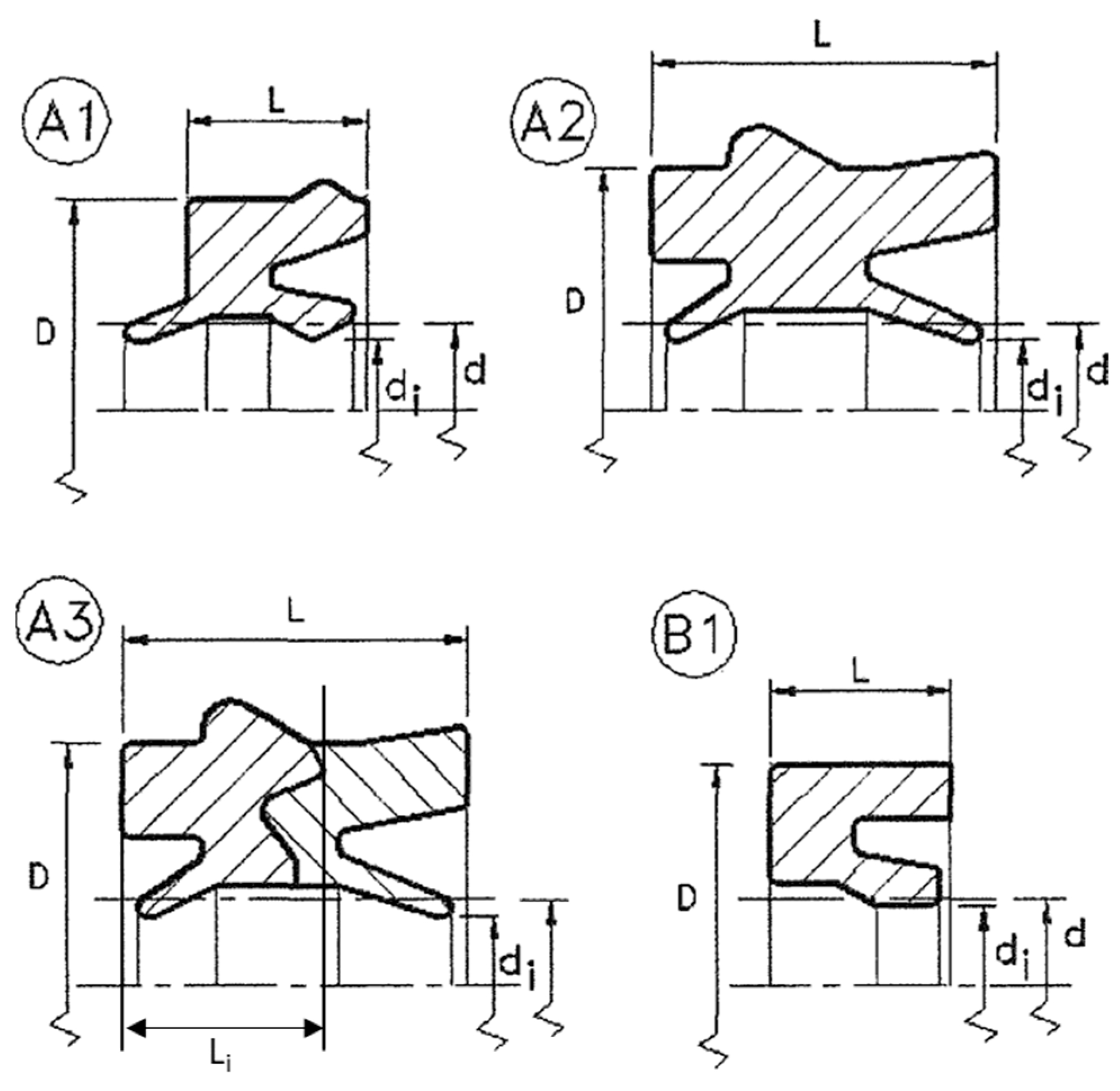
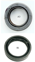
2.1. Seal Types
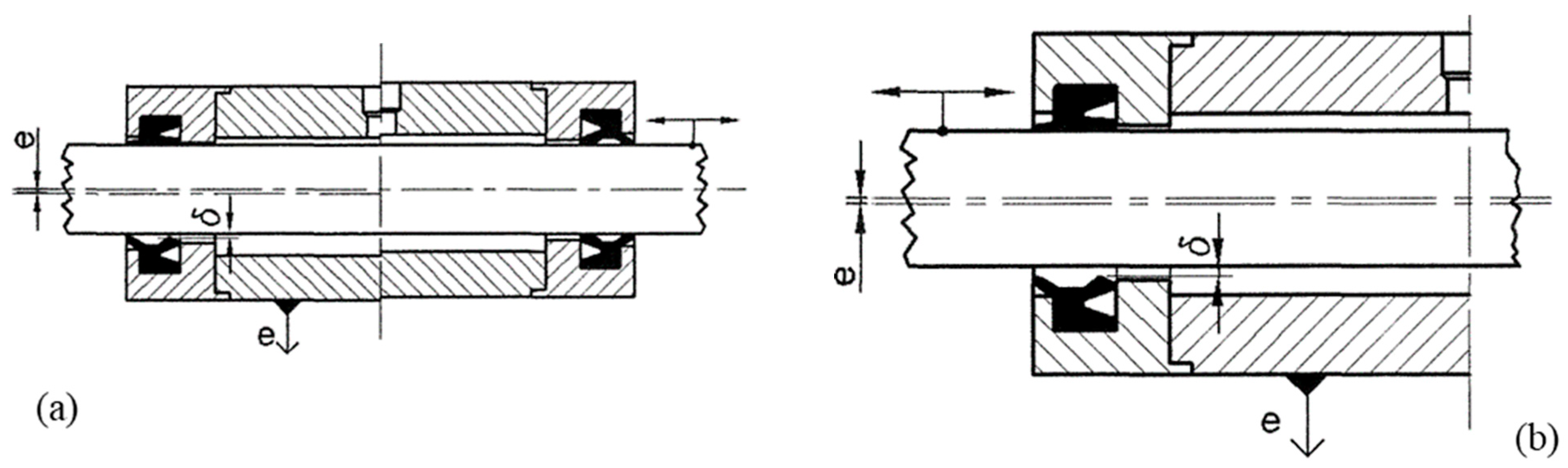
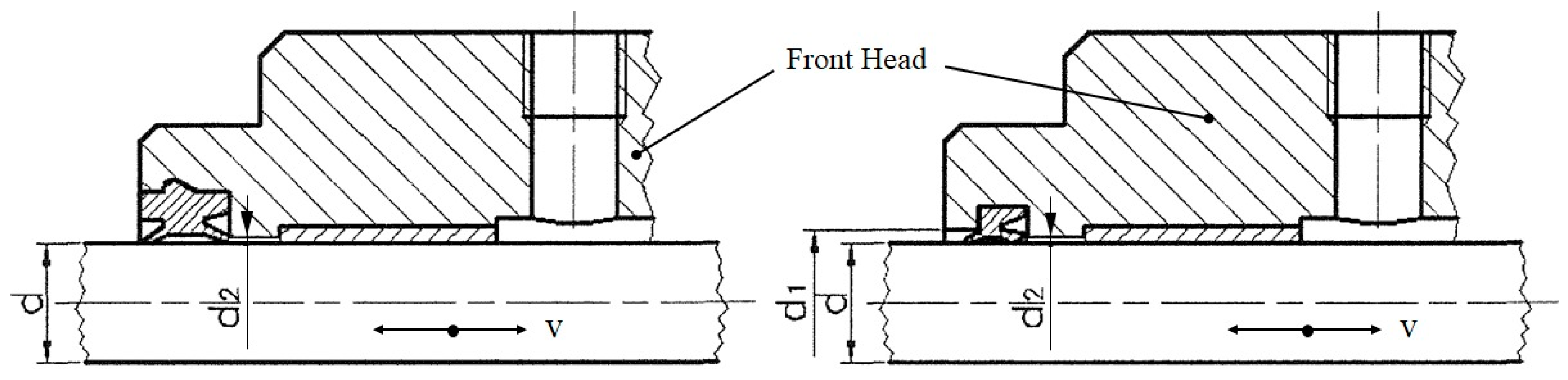
2.2. Common Rod Seal Mountings
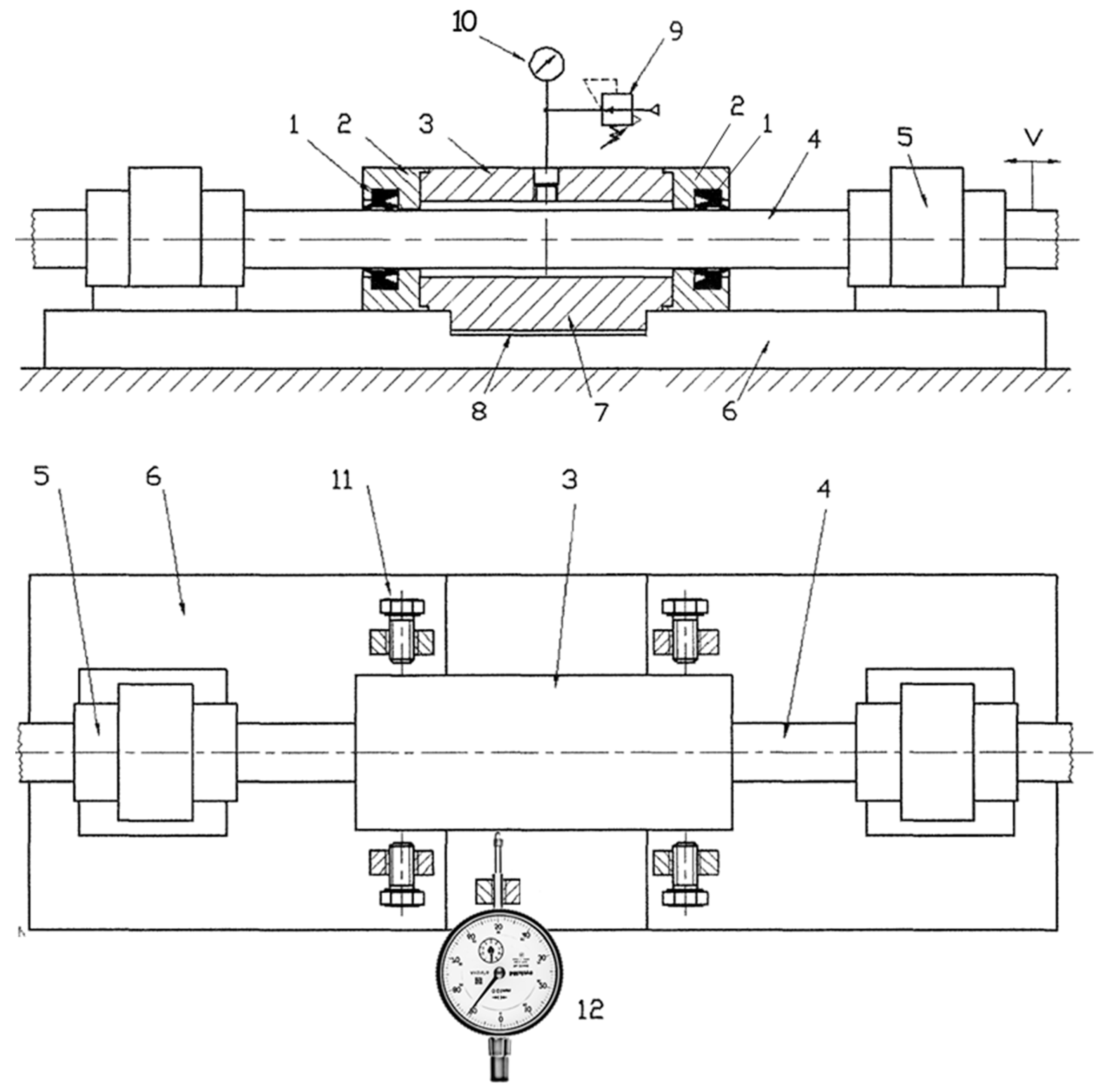
2.3. Dedicated Test Bench
2.4. Endurance Test Methodology
3. Results
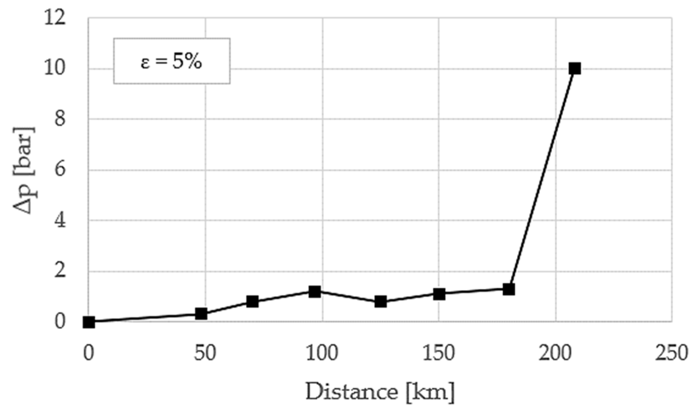
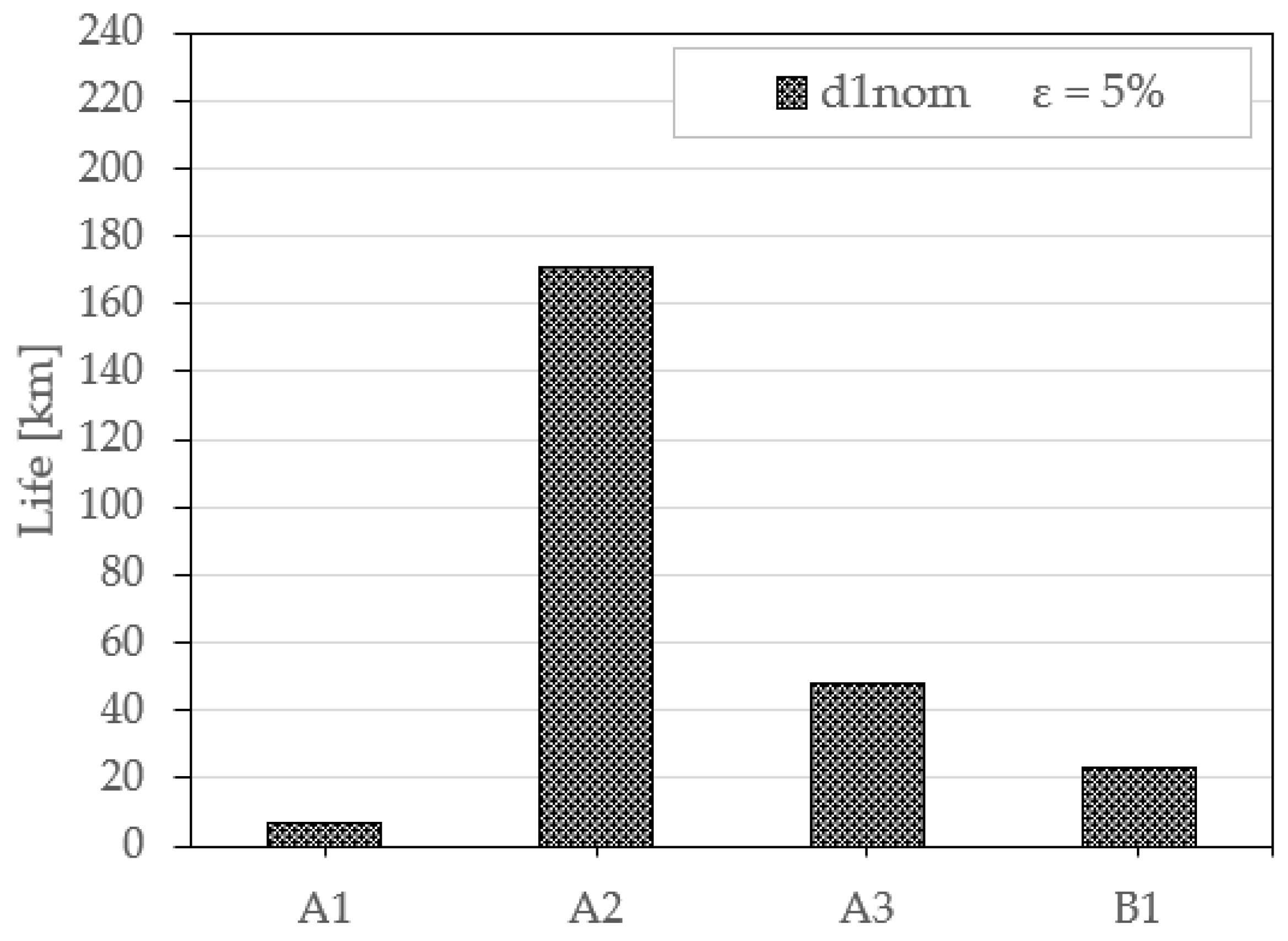
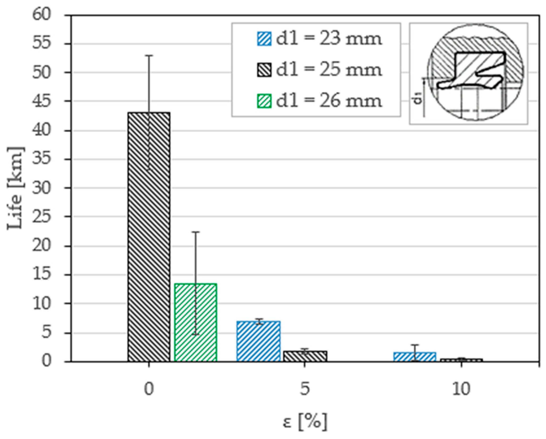
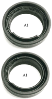
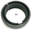
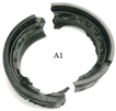
3.1. Seal Type A1
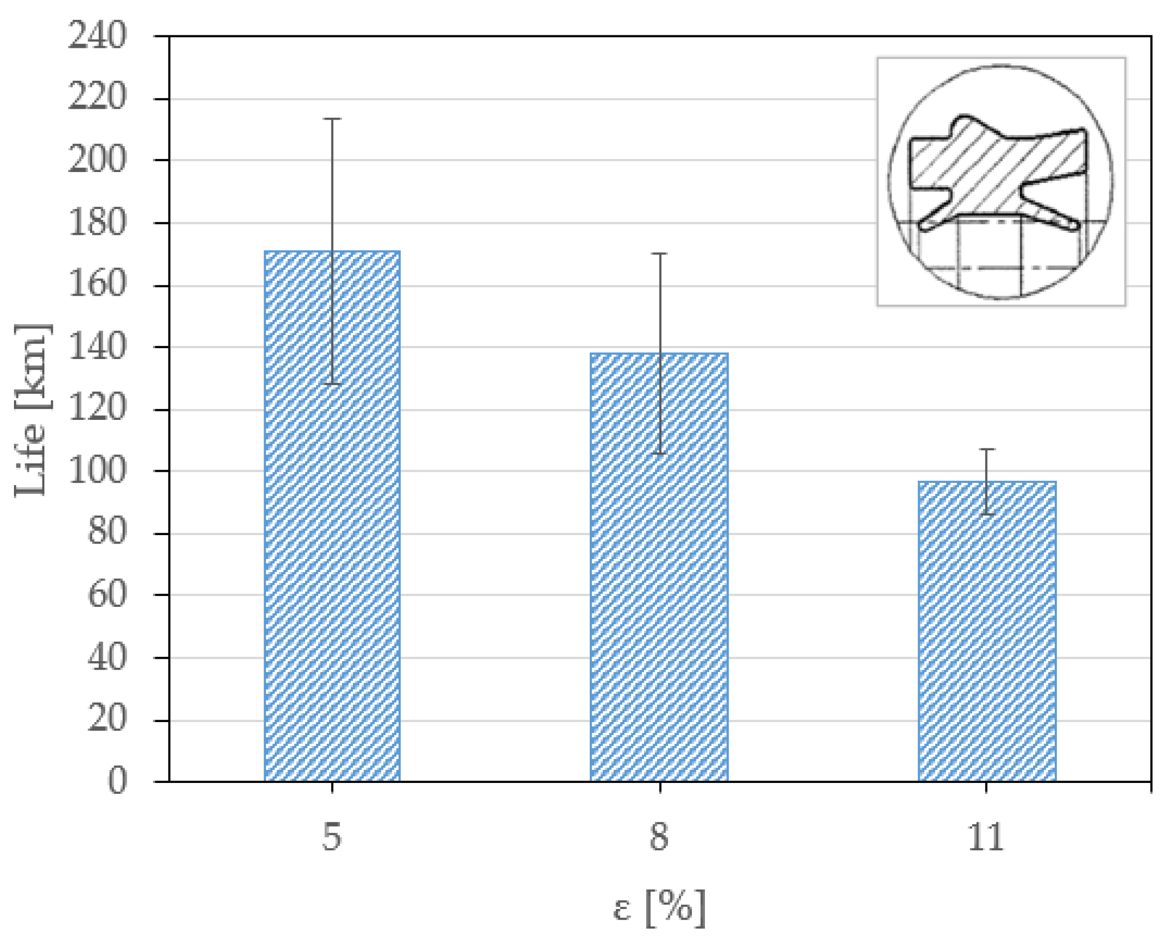
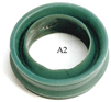
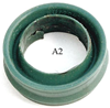
3.2. Seal Type A2
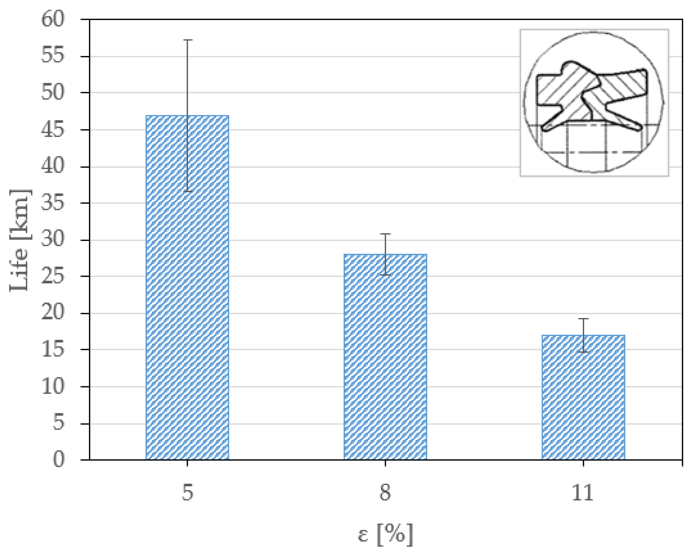
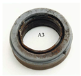
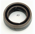
3.3. Seal Type A3
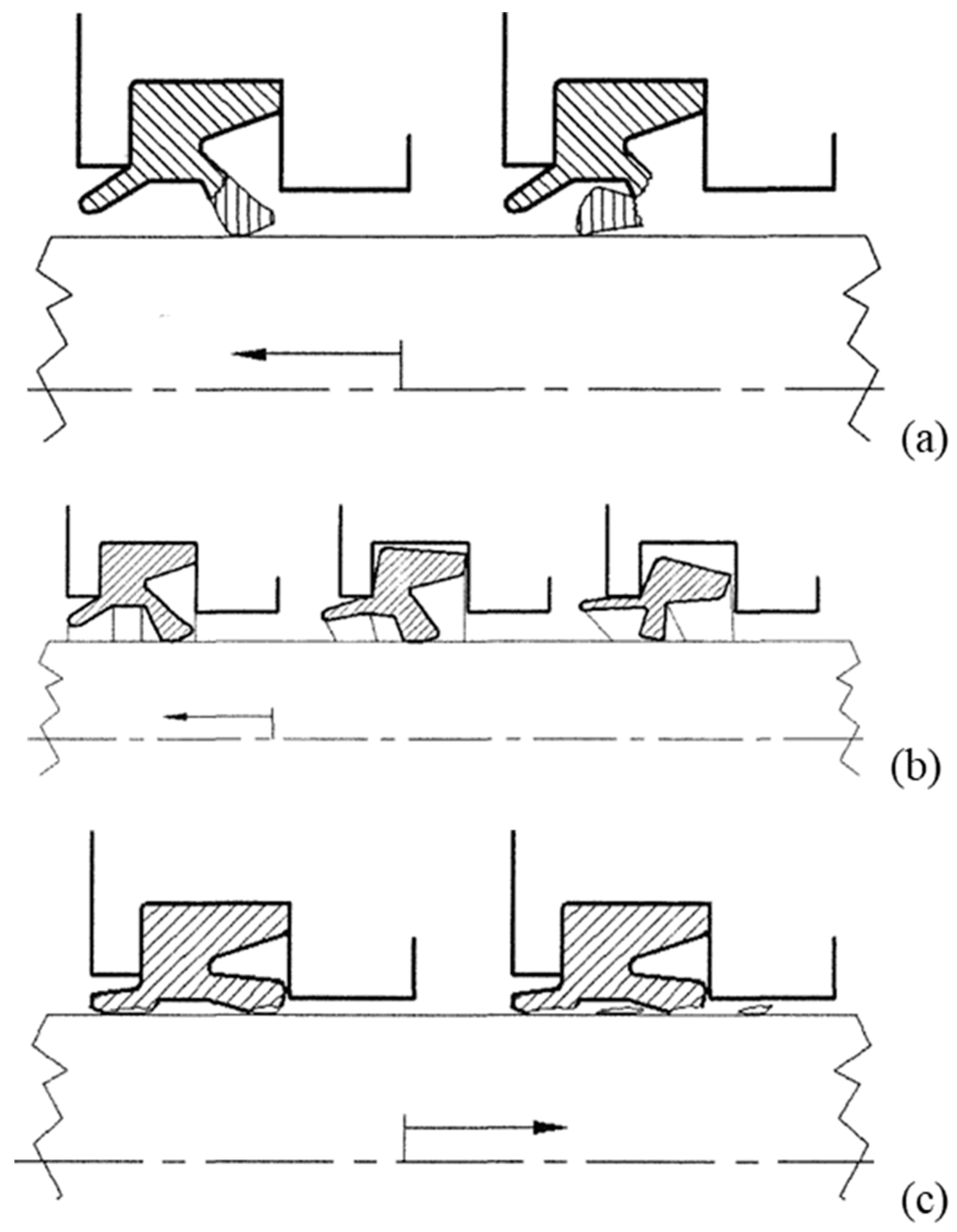
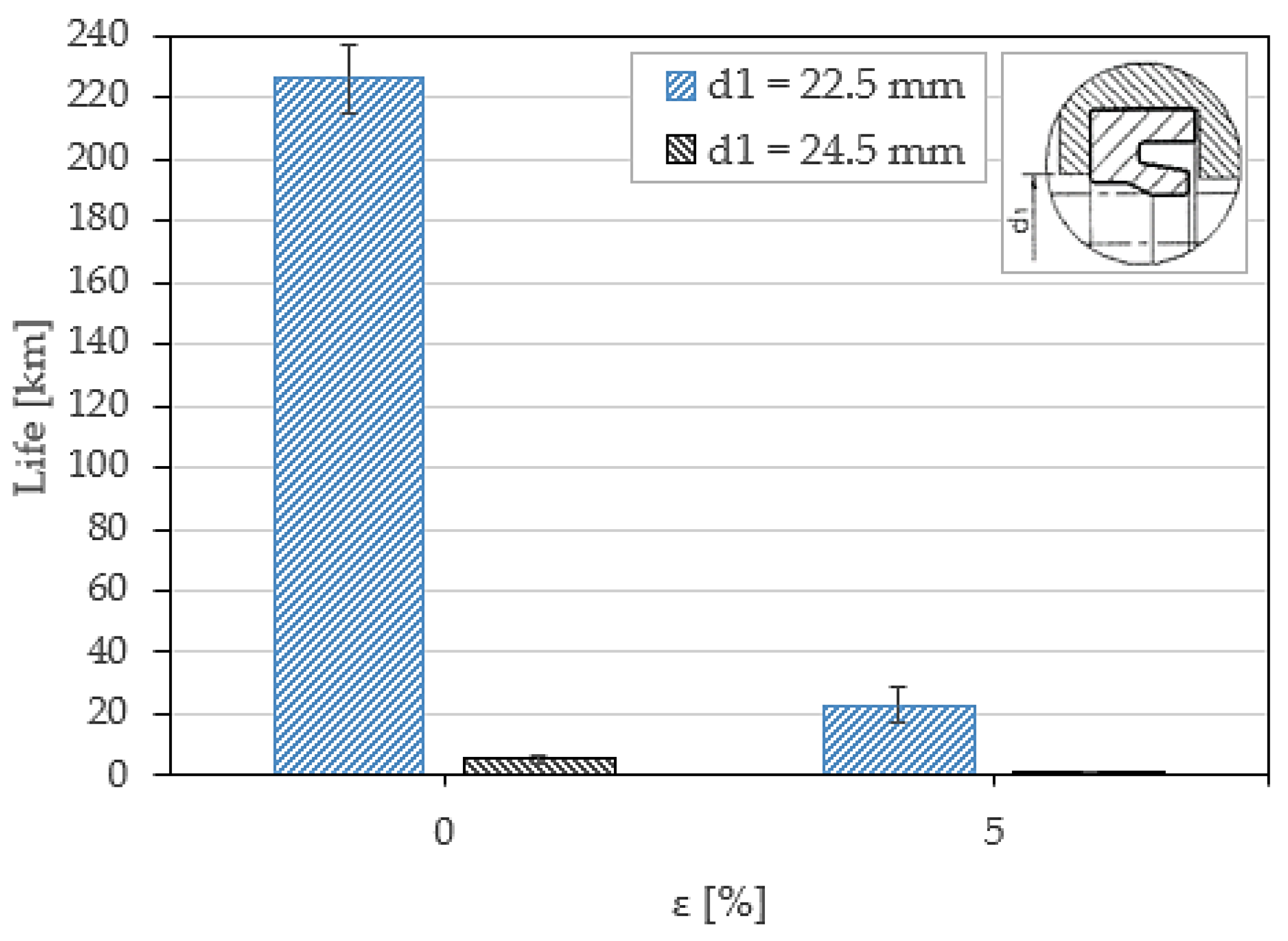
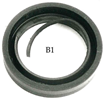
3.4. Seal Type B1
4. Discussion
5. Conclusions
Author Contributions
Funding
Data Availability Statement
Conflicts of Interest
References
- Baart, P.; Lugt, P.M.; Prakash, B. Review of the lubrication, sealing, and pumping mechanisms in oil- and grease-lubricated radial lip seals. Proc. Inst. Mech. Eng. Part J J. Eng. Tribol. 2009, 223, 347–358. [Google Scholar] [CrossRef]
- Cuijpers, M.J.M. The sealing mechanism of lip seals for rotating shafts. Constructeur 1985, 224, 22–31. [Google Scholar]
- Burenin, V. New lip-type seals for sealing of rotating shafts. Russ. Eng. Res. 1997, 217, 89–93. [Google Scholar]
- Belforte, G.; Raparelli, T.; Mazza, L. Analysis of Typical Component Failure Situations for Pneumatic Cylinders Under Load. Lubr. Eng. 1992, 48, 840–845. [Google Scholar]
- C.N.O.M.O. 06.0700; Cahier des Charges de Reception et d’Homologation. CNOMO: Boulogne-Billancourt, France, 1968.
- C.N.O.M.O. E06.22.115.N; Verins Pneumatiques Controle Qualitatif. CNOMO: Boulogne-Billancourt, France, 1992.
- ISO 10099:2001; Pneumatic Fluid Power—Cylinders—Final Examination and Acceptance Criteria. ISO: Genève, Switzerland, 2001.
- ISO/TR 16194:2017; Pneumatic Fluid Power: Assessment of Component Reliability by Accelerated Life Testing. General Guidelines and Procedures. ISO: Genève, Switzerland, 2017.
- ISO 19973-1:2015; Pneumatic Fluid Power: Assessment of Component Reliability by Testing. Part 1: General Procedures. ISO: Genève, Switzerland, 2015.
- Belforte, G.; Manuello Bertetto, A.; Liu, S.; Mazza, L. Wear and Failure Analysis in Pneumatic Cylinders Under Radial Load. In Proceedings of the 11th International Sealing Conference, Dresden, Germany, 3–4 May 1999. [Google Scholar]
- Hobson, R. Leakage from Reciprocating Hydraulic Seals due to Solid Contamination. In Proceedings of the 15” International Conference on Fluid Sealing, Maastricht, The Netherlands, 16–18 September 1997; Halligan, B.D., Ed.; BHRA: Cranfield, UK, 1997. [Google Scholar]
- Chen, J.; Wu, Q.; Bai, G.; Ma, J.; Wang, Z. Accelerated Life Testing Design Based on Wear Failure Mechanism for Pneumatic Cylinders. In Proceedings of the 8th International Conference on Reliability, Maintainability and Safety, Chengdu, China, 20–24 July 2009. [Google Scholar]
- Chang, M.S.; Kwon, Y.I.; Kang, B.S. Design of reliability qualification test for pneumatic cylinders based on performance degradation data. J. Mech. Sci. Technol. 2014, 12, 4939–4945. [Google Scholar] [CrossRef]
- Belforte, G.; Raparelli, T.; Mazza, L. Life tests on elastomeric lip seals for pneumatic cylinders. Tribotest 1997, 3, 251–266. [Google Scholar] [CrossRef]
- Stolarski, T. Tribology in Machine Design; Butterworth Heinemann: Oxford, UK, 2000. [Google Scholar]
- Zum Gahr, K. Microstructure and Wear of Materials; Elsevier Science: Amsterdam, The Netherlands, 1987. [Google Scholar]
- Wassink, D.B.; Lenss, V.G.; Levitt, J.A.; Ludema, K.C. Phisically Based Modeling of Reciprocating Lip Seal Friction. J. Trib. 2001, 123, 404–412. [Google Scholar] [CrossRef]
- Debler, C.; Gronitzki, M.; Poll, G. Investigation into the Sealing Contacts of Reciprocating Elastomeric Seals—Correlation of Calculations with Contact Force Measurements and Optical Observations. In Proceedings of the 17th International Conference on Fluid Sealing, York, UK, 8–10 April 2003; Hoyes, J., Ed.; BHRA: Cranfield, UK, 2003. [Google Scholar]
- Lee, C.Y.; Lin, C.S.; Jian, R.Q.; Wen, C.Y. Simulation and experimentation of the contact width and pressure distribution of lip seals. Tribol. Int. 2006, 39, 915–920. [Google Scholar] [CrossRef]
- Belforte, G.; Conte, M.; Mazza, L. Low friction multi-lobed seal for pneumatic actuators. Wear 2014, 320, 7–15. [Google Scholar] [CrossRef]
- Qian, P.; Pu, C.; Liu, L.; Li, X.; Zhang, B.; Gu, Z.; Meng, D. Development of a new high-precision friction test platform and experimental study of friction characteristics for pneumatic cylinders. Meas. Sci. Technol. 2022, 33, 065001. [Google Scholar] [CrossRef]
- Juoksukangas, J.; Lehtovaara, A.; Miettinen, J.; Tolvanen, P.; Järvelä, P.; Niemi, A.M. Development of a test rig for reciprocating seals in heavy load condition. In Proceedings of the Nordtrib Conference, Storforsen, Sweden, 8–11 June 2010. [Google Scholar]
- Neale, M.; Gee, M. Wear Problems and Testing for Industry; William Andrew Publishing: Norwich, UK, 2001. [Google Scholar]
- Calvert, C.; Tirovic, M.; Stolarsk, T. Design and development of an elastomer-based pneumatic seal using finite element analysis. Proc. Inst. Mech. Eng. Part J J. Eng. Tribol. 2002, 216, 127–138. [Google Scholar] [CrossRef]
- Belforte, G.; Conte, M.; Manuello, A.; Mazza, L. Performance and Behavior of Seals for Pneumatic Spool Valves. Tribol. Trans. 2010, 54, 237–246. [Google Scholar] [CrossRef]
- Barillas, G.; Wangenheim, M.; Kinsch, P.; Jäckel, J. The T-Ring Principle: A sophisticated approach of sealing dynamically. In Proceedings of the 5th World Tribology Congress, Torino, Italy, 8–13 September 2013. [Google Scholar]
- Raparelli, T.; Mazza, L.; Trivella, A. Experimental analysis and preliminary model of non-conventional lip seals. Tribol. Int. 2023, 181, 108311. [Google Scholar] [CrossRef]
- Mokhtar, M.; Mohamed, M.; El-Giddawy, M.; Yassen, S. On the effect of misalignment on the performance of U-type lip seal. Wear 1998, 223, 139–142. [Google Scholar] [CrossRef]
- Pinedo, B.; Aguirrebeitia, J.; Conte, M.; Igartua, A. Tridimensional eccentricity model of a rod lip seal. Tribol. Int. 2014, 78, 68–74. [Google Scholar] [CrossRef]
- Bekgulyan, S.; Feldmeth, S.; Bauer, F. Influence of static and dynamic eccentricity on the pumping rate of radial lip seals. In Proceedings of the 25th International Conference on Fluid Sealing, Manchester, UK, 4–5 March 2020. [Google Scholar]
- ISO 15243:2017; Rolling Bearings—Damage and Failures. ISO: Genève, Switzerland, 2017.
- Gear Failure Atlas—Manual; AGMA: Alexandria, VA, USA, 2020.
- ISO 10825-1:2022; Gears—Wear and Damage to Gear Teeth—Part 1: Nomenclature and Characteristics. ISO: Genève, Switzerland, 2022.
- Merkle, L.; Baumann, M.; Bauer, F. Influence of alternating temperature levels on the wear behavior of radial lip seals: Test rig design and wear analysis. Appl. Eng. Lett. 2021, 6, 111–123. [Google Scholar] [CrossRef]
- Straffelini, G. Friction and Wear. Springer: Berlin/Heidelberg, Germany, 2015. [Google Scholar]
- Stachowiak, G.; Batchelor, A. Engineering Tribology, 4th ed.; Butterworth-Heinemann: Oxford, UK, 2013. [Google Scholar]


| Type | Material | Hardness (IRHD) | Dimensions (mm) | |||
|---|---|---|---|---|---|---|
| d | D | L | Li | |||
| A1 | Nitrile rubber | 75 | 20 | 30 | 5.5 | - |
| A2 | Polyurethane | 90 | 20 | 30 | 10.5 | - |
| A3 | Nitrile rubber + Acetal resin | 80 | 20 | 30 | 11 | 5.5 |
| B1 | Nitrile rubber | 78 | 20 | 30 | 7.5 | - |
| Type | d (mm) | d1,nom (mm) | Δd1 (%) | e (mm) | ε (%) |
|---|---|---|---|---|---|
| A1 | 20 | 23 | 0, 8, and 13 | 0 to 1 | 0 to 10 |
| A2 | 20 | - | - | 0.5 to 1.1 | 5 to 11 |
| A3 | 20 | - | - | 0.4 to 1 | 4 to 10 |
| B1 | 20 | 22,5 | 0 and 7 | 0 to 0.5 | 0 to 5 |
| Picture | Description | Dominant Failure Mode |
|---|---|---|
 | Serious distributed loss of chunks of material from the sealing edge of lips (sometimes followed by tearing of the whole lip) due to operation under high mounting eccentricity. | Mode I |
  | Bulk continuous tearing of the sealing edge of the lip due to partial extrusion from the seat associated with a reduced retaining action of the shoulder (due to an increase in the diameter d1 of the seat shoulder). Sometimes, the lip detachment occurs without complete loss of material from the contact site. Failure often indicates the region where extrusion took place during the tests, and cross-section distortion of the seal during wear cycles may also be experienced in these regions. | Mode II and Mode I |
 | Cracking of the sealing ring produced by a radial cut due to the complete ejection of the seal from its seat. | Mode II |
 | Catastrophic failure with tearing of the lips followed by eventual cracking of the sealing body in two or more parts. It is associated with extreme cases where the ejection of the seal from its seat occurs under very high eccentricity coupled with a large diameter d1 of the retaining shoulder. | Mode II and Mode I |
  | Wearing out of the lip edge sliding against the steel rod is associated with the thinning of the lip and formation of jagged edges in the mostly loaded region of the seals (where the compression action of the rod, due to the eccentricity mounting, is greatest). Circumferential cracks may appear in the seal region where the compression against the rod is lower, and the lip tends to detach from the rod. | Mode III (Abrasion) |
 | Weakening of the lip section as a result of thinning may be so extended, and some portions of the sealing ring may be torn off by sticking and ejected. | Mode III (Adhesion–abrasion) |
  | During wearing out of the lip, some portions of the sealing edge may be ejected due to adhesive effects in the region where the eccentricity is maximum. | Mode III (Adhesion) |
 | Eccentricity misalignment of the rod reflected as thinning of the lip, which may produce a brittle failure of the sealing edge, and axial cracks may be observed in the region where the rod abraded the most. | Mode III (Abrasion) and cracking |
 | Wearing out may develop as plastic deformation of the lip followed by thinning. Residual compression set is observed when the seal is taken out of its seat. | Mode III (Abrasion) and plastic deformation |
Disclaimer/Publisher’s Note: The statements, opinions and data contained in all publications are solely those of the individual author(s) and contributor(s) and not of MDPI and/or the editor(s). MDPI and/or the editor(s) disclaim responsibility for any injury to people or property resulting from any ideas, methods, instructions or products referred to in the content. |
© 2024 by the authors. Licensee MDPI, Basel, Switzerland. This article is an open access article distributed under the terms and conditions of the Creative Commons Attribution (CC BY) license (https://creativecommons.org/licenses/by/4.0/).
Share and Cite
Mazza, L.; Goti, E. Failure and Damage of Reciprocating Lip Seals for Pneumatic Cylinders in Dry Conditions. Lubricants 2024, 12, 119. https://doi.org/10.3390/lubricants12040119
Mazza L, Goti E. Failure and Damage of Reciprocating Lip Seals for Pneumatic Cylinders in Dry Conditions. Lubricants. 2024; 12(4):119. https://doi.org/10.3390/lubricants12040119
Chicago/Turabian StyleMazza, Luigi, and Edoardo Goti. 2024. "Failure and Damage of Reciprocating Lip Seals for Pneumatic Cylinders in Dry Conditions" Lubricants 12, no. 4: 119. https://doi.org/10.3390/lubricants12040119
APA StyleMazza, L., & Goti, E. (2024). Failure and Damage of Reciprocating Lip Seals for Pneumatic Cylinders in Dry Conditions. Lubricants, 12(4), 119. https://doi.org/10.3390/lubricants12040119