Article

Failure and Damage of Reciprocating Lip Seals for Pneumatic Cylinders in Dry Conditions

Department of Mechanical and Aerospace Engineering, Politecnico di Torino, Corso Duca degli Abruzzi 24, 10129 Torino, Italy
*
Author to whom correspondence should be addressed.
Lubricants 2024, 12(4), 119; https://doi.org/10.3390/lubricants12040119
Submission received: 22 February 2024 / Revised: 28 March 2024 / Accepted: 31 March 2024 / Published: 4 April 2024
(This article belongs to the Special Issue Wear Mechanism Identification and State Prediction of Tribo-Parts)

Abstract

:
Lip seals are components subjected to high mechanical stress and they are responsible for many out-of-service in pneumatic cylinders. The aim of this work is the development of an experimental methodology to evaluate lifetime duration and analyse failures and damages of rod lip seals for pneumatic cylinders. A dedicated test bench was designed and manufactured which reproduces actual working conditions of the seals i.e., compressed air action (seal pressurisation) and relative linear reciprocating motion. Three types of seals made of two elastomers (NBR and polyurethane) were tested; dry condition was considered to speed up the tests. The influence of geometric parameters like seal seat dimension and seal axis misalignment with respect to the rod axis, was analysed by multiple experimental tests. Results in terms of seal life duration and failure modes are presented which allow comparison of seals performance and provide a helpful tool to end-users in a proper selection of seals geometry, material and key working parameters.

1. Introduction

Seals are commonly used in many industrial applications [1], e.g., in bearings and in pneumatics, as both rotating [2,3] and linear sliding elements. Among these, lip seals are widely employed in linear pneumatic actuators because of their excellent seal capability due to the radial deformation of the lip; indeed, under the pressure of compressed air, the lip is pushed in contact against its counterpart (cylinder barrel or rod), thus developing the sealing action. To allow the mentioned working principle, lip seals are, therefore, mounted in proper seat housing, machined on the piston or in the front head to ensure sealing either between the front and rear cylinder chambers or between the front chamber, crossed by the piston rod, and the ambient. Out-of-service linear pneumatic actuators are closely connected to wear phenomena and failure of the seals. In particular, rod seals suffer the highest failure rate, and it is the main reason for actuator failure together with piston seals. Despite actuators having guiding systems, such as guide bushings and guide rings, to centre the rod and bear working loads, part of the applied radial load is always transferred to seals. Wear of the guide systems, especially the guide rod bushing, is unavoidable and determines increased gaps with subsequent misalignment of the rod under the action of the external load. This leads to incorrect operation of the seals and rapid wearing out [4].
Knowledge of friction and the wear phenomena of seals is, therefore, fundamental in the design phase of actuators for the evaluation of their performance, i.e., in terms of maximum tolerated force and estimated duration and for proper predictive maintenance. In addition, it is also very important to understand how sealing takes place to limit or eliminate leakages of fluid through the seals and ensure efficient operation of the actuator throughout its whole lifespan. The relevance of the wear and tear phenomena of sliding seals on the performance and durability of pneumatic actuators has always aroused the interest of standardisation bodies and researchers. Regulations and international standards [5,6,7,8,9] define standard methods for testing pneumatic cylinders under continuous cyclic movement of the rod with a radial load acting on it. The out-of-service condition of the cylinder is determined by the presence of leakages above a given threshold of acceptability. Belforte et al. [10] and Hobson et al. [11] proposed new experimental methodologies based on the indications provided by the standards that allow for accelerated laboratory life tests to be performed on pneumatic cylinders without modifying failure modes. After the actuator breakdown, a visual inspection of each component, including seals, was carried out and led to the identification of the different causes of failure and different types of seal damage (front seal extrusion, spinalisation, adhesive wear, abrasion and others). Similar approaches were followed by [12,13], who applied the Weibull statistical approach to their results according to [9]. Specific test benches on complete components equipped with seals were developed to reproduce in-service conditions as closely as possible and to provide a better understanding of seal behaviour as a function of fluid pressure, velocity and direction of motion. A suitably designed test machine to perform many simultaneous accelerated life tests with a piston seal of pneumatic cylinders was also presented in [14]. The results of accelerated tests have highlighted the influence of the seal shape, material and greasing condition on the overall endurance of pneumatic cylinders. Post-mortem analysis demonstrated the importance of ensuring correct greasing and the presence of a relationship between damages and leakages. Wear and failure modes of lip seals [15], including adhesion–abrasion mechanisms [16], are, in turn, related to contact pressure distribution and friction. Investigations into the contact mechanics and frictional behaviour of reciprocating lip seals were presented in [17,18,19,20,21] through experimental and numerical approaches. The importance of investigating contact forces and friction forces on actual seals was also shown by Juoksukangas et al. [22] instead of resorting to laboratory testing on samples [23]. Calvert et al. [24], Belforte et al. [25] and Barillas et al. [26] proposed the redesign and optimisation of seal cross-section geometry based on finite element analysis and friction experiments. Interestingly, the results suggested that failure modes change according to geometry, but seal life and durability may not be directly affected. Also, innovative operating modes of lip seals were proposed to reduce friction and wear of linear reciprocating lip seals [27].
In this work, the problem of wear and failure in rod lip seals was addressed in a more specific way. A dedicated test bench was designed that allows for the testing of individual seals independently from any specific application, which differs from the multi-component approach suggested by the standards. The bench can replicate the typical operating conditions of seals mounted inside the front head of a pneumatic cylinder, including reciprocating motion and air chamber pressurisation. Dry tests were performed to replicate the industrial operative conditions of pneumatic cylinders, in which inner grease shortage or complete loss is commonly achieved. Three types of seals with rod scrapers made from different materials and one type of seal without a rod scraper were considered in this research. Also, the effect of increasing radial eccentricity was investigated since misalignment has been proven to be a key aspect in lip seals [28,29,30]. Multiple tests were carried out with the aim of identifying the impact of the seal geometry, seal cross-section shape, seal material and eccentric misalignment on the lifetime of the seals and on the dominant failure modes. Compared with previous research, such an approach allows for wear and failure problems in single seals to be addressed in a more comprehensive way. The results in terms of seal life duration and failure modes are presented, which allow for a comparison of performance. An atlas of typical component failure is proposed in the end, similar to what has already been proposed for other mechanical components [31,32,33]. Each type of failure and damage will be associated with its cause, and the operating conditions that led to it will be analysed and discussed.

2. Materials and Methods

2.1. Seal Types

Commercial lip seals commonly used in pneumatic cylinder rods were tested. Elastomers are the commonest material in fluid sealing thanks to certain valuable physical properties, just to mention a few: abrasion, chemical and temperature resistance. In this research, the material choice fell into the widespread materials for pneumatic cylinders: acrylonitrile (NBR) and polyether polyurethane (EU). NBR features good abrasion resistance, good temperature range (commonly −30÷120 °C) and mineral grease compatibility; EU is characterised by high abrasion resistance but lower temperature range than NBR.
Figure 1 shows the geometry of the four lip seals considered in this work. Seals with code A1, A2, A3 feature a rod scraper, whereas type B1 is without any rod scraper. Table 1 lists the material, the hardness in terms of IRHD points and the main geometric dimensions for each type, where d represents the nominal diameter of the rod, d i   the innermost diameter of the rubber lip in its unloaded configuration and L is the nominal width of the seal seat into the housing. All seals are manufactured by thermal moulding process. Seals A2 and A3 have similar cross-sections and size; however, their geometries are slightly more complex than A1 and B1. Larger axial and radial dimensions of seals A2 and A3 give greater stiffness to the section. Seal A3 is made of two elements: the seal is nitrile rubber (NBR), and the rod scraper is acetal resin. L i indicates the axial length of the rod scraper.

2.2. Common Rod Seal Mountings

Figure 2 shows two mounting solutions of seals in the front head of a pneumatic cylinder: with fixing rubber ridge (left-side) and grooved seat (right side). For seals A2 and A3, the assembly is ensured by an annular ridge that matches a dedicated groove machined in the seat; the ridge constrains the seal axially, preventing it from coming out of the seat during operation. Seals A1 and B1 rely on a grooved seat mounting. As known, the sealing mechanism relies on the elasticity and incompressibility of the elastomer and the existence of a mounting interference; indeed, this is allowed by the inner diameter di of the lip (Figure 1), which is smaller than the rod diameter d (Figure 1 and Figure 2). Diameters d1 and d2 refer to the left-side and right-side axial shoulders of the seat. The sealed pressure is located on the right side of the front head in the front chamber of the pneumatic cylinder (not shown in Figure 2). As shown, the rod is animated by reciprocating motion, which involves seal and guide-bearing abrasion. This wear mechanism is responsible for an increasing gap between rod-guide mating surfaces, which appears as rod misalignment with subsequent degradation and failure of the seal.

2.3. Dedicated Test Bench

A dedicated test bench for endurance tests of lip seals was designed and built. The test set-up was performed, taking into consideration test rigs for rotary lip seals [28,34]; however, it focused on the specific and peculiar features for testing reciprocating lip seals. The bench allows the user to test seals in a variety of operating conditions to assess the lifetime with respect to the residual sealing capability of the seals. In particular, the set-up allows for seal pressurisation and reciprocating motion to be reproduced as in a real mounting in a pneumatic cylinder. To replicate rod misalignment, as described above, and the subsequent variation in the seat shoulder diameters, the set-up allows the main geometric size of the seat to be varied. The investigated parameters were diameter d1 and rod seal axis misalignment (eccentricity), which can be varied independently. Sealed pressure and reciprocating velocity were kept constant during the tests.
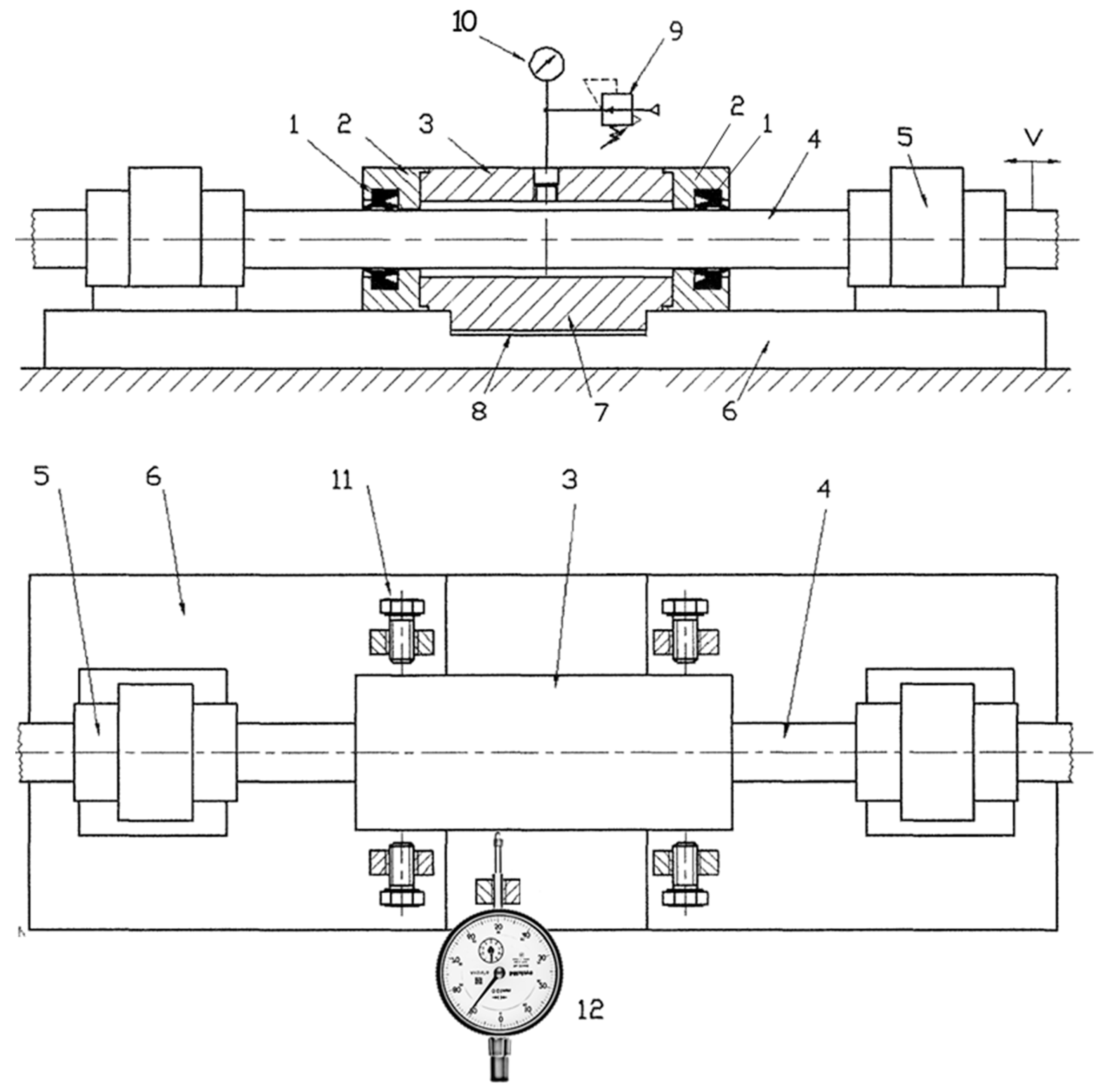
Based on these requirements, the test bench shown in Figure 3 was designed and manufactured. Seals under test (1) were installed into proper seats machined into the end caps (2) of the chamber (3). Several end plates (2) of the chamber were machined for interchangeability aims based on the different geometries and dimensions of the seal seats under test. The rod (4) moves according to a reciprocating linear motion v produced by a driving pneumatic cylinder (not shown in the figure); this axial movement of the rod is assured by a couple of linear recirculating ball bearings (5) constrained to the base plate (6). The ridge (7) matches the groove (8) machined in the base plate (6) and creates a prismatic guide with an axis orthogonal to that of the rod, which prevents the test chamber from moving axially. The driving pneumatic cylinder and the base plate are rigidly fixed to an external frame. By means of the adjustment screws (11), it is possible to set the offset between the axis of the chamber (3) and, therefore, of the seals with respect to the rod axis (4). The offset value, or radial eccentricity e , is read off by the centesimal dial gauge (12). The pressure inside the test chamber is regulated by means of the pressure reducer (9) and measured by the pressure gauge (10).
For a better understanding, Figure 4a shows the test chamber in two positions: on the right side of the schematic, the chamber is in the centred position, the axis with the rod on the left in the eccentric position of quantity e with respect to the axis of the rod. Due to eccentricity, the elastomer seal deforms and compresses at the top; if eccentricity e is sufficiently large, the lip may detach from the rod by a gap δ clearly visible in the detail of Figure 4b. This lack of contact encourages cogging and sticking of the lip under the action of pressurised air, which promotes bulk tearing phenomena.

2.4. Endurance Test Methodology

Regarding the test conditions, it is worthwhile to consider that pneumatic cylinders are usually greased for life; therefore, rod seals operate with a film of grease between the lip and the rod contact surfaces. However, during actual working conditions in an industrial environment, a decrease in the initial amount of grease is always observed, which lets the seals operate in more severe conditions than expected. Liquid droplets, not removed by inline filtration and carried by pressurised air flow into the cylinder chamber, may produce a washing-out effect of grease. When grease starvation occurs, an additional abrasive action from debris not removed by the rod scraper affects the integrity of seals. Other grease removal actions are observed, as well. For these reasons, tests were carried out in dry conditions, which, moreover, allowed for a reduction in the scattering of experimental data due to the effectiveness of grease lubrication during the tests. Nonetheless, tests carried out in dry conditions showcase the typical failure modes within a reasonable time duration of the tests.
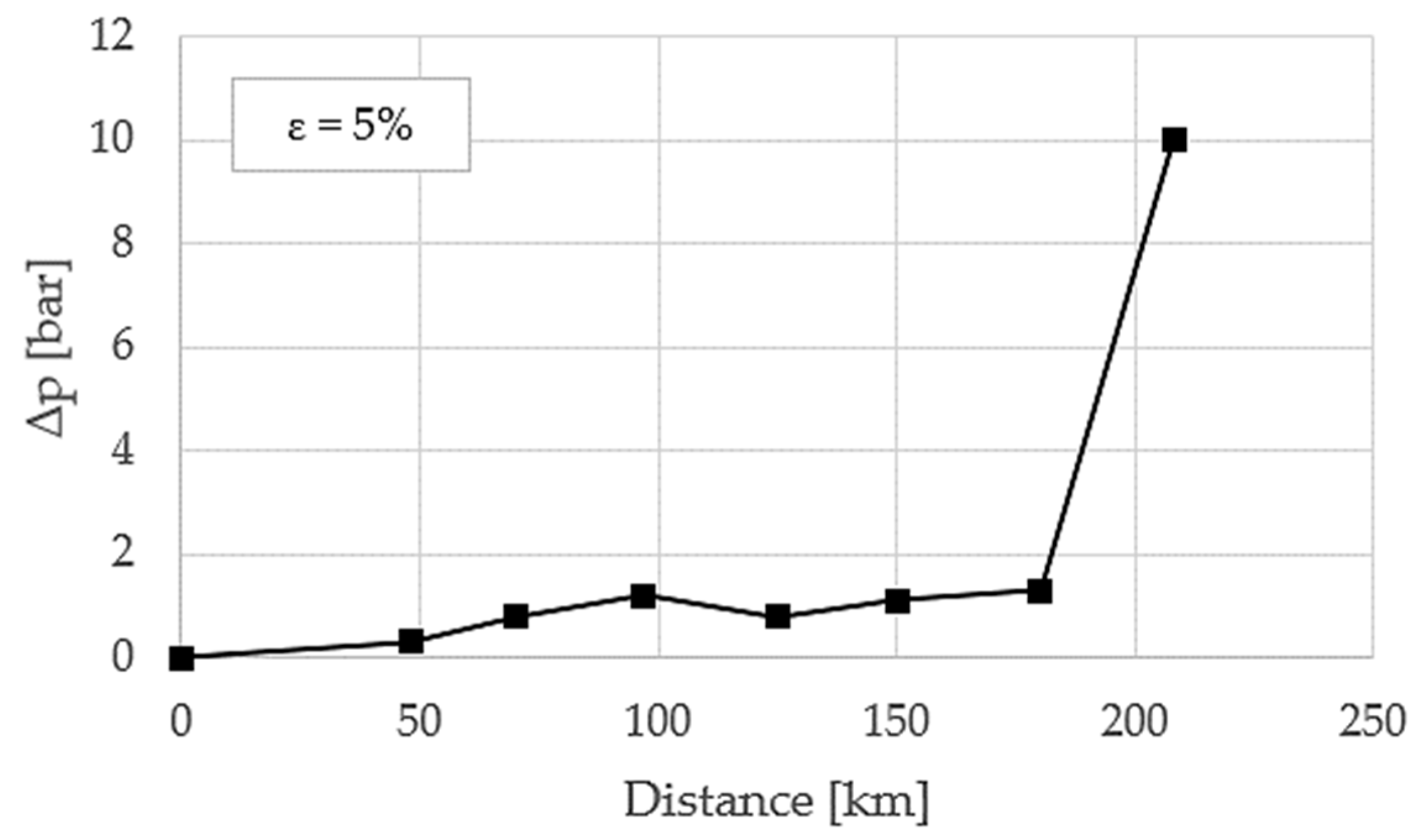
The reciprocating linear movement of the rod of the test bench is obtained by connecting the rod to a pneumatic cylinder with a stroke of 500 mm, controlled by a 5/2 two-stable positions electro valve. The distance travelled by the rod is recorded, and tests are carried out until the seals mounted in the test chamber are no longer able to guarantee their sealing function; this distance expresses the lifetime of the seals under the considered test conditions. To this aim, the movement of the rod was periodically interrupted, and leakages (through the seals) were assessed by measuring the pressure drop in the inner test chamber between the seals. The chamber is filled to the initial pressure of 10 bar (relative value), and after 1 h, the pressure decrease p is read. Leakage test is carried out even before starting the tests to check for leakages due to mounting eccentricity. Seals are considered out of service when the pressure drop p is equal to 10 bar, which corresponds to the complete emptying of the chamber down to the ambient pressure. Figure 5 shows an example of a leakage test. The pressure drop to failure is usually recorded as a peak after an extended period of run where pressure drop increases slowly; during this period, a variable behaviour is detected even with possible recovery of sealing capability. Then, close to failure, the sealing capability is usually lost abruptly.
Several tests were carried out by varying diameter d 1 of the front shoulder of the seat and eccentricity e   . The diameter d 2 of the rear shoulder of the seat was suitably enlarged to allow the offset between the test chamber and the rod. Seals A2 and A3 do not have the front shoulder of the seat; therefore, only the effect of eccentricity was taken into account. The case with null eccentricity was investigated only when the seat shoulder diameter was varied; otherwise, an overly long endurance of the seal would be expected in such low-stress test conditions. Table 2 also shows the range of variation in the geometric entities considered for each seal; each variation is related to the nominal value of the magnitude itself.
Operating conditions during endurance tests were pressure of 4 bar (relative pressure) and sliding speed of 0.2–0.3 m/s. The rod was made of hardened steel with surface roughness of Ra = 0.4 µm to replicate a common rod for pneumatic cylinders.
In the following, the radial eccentricity e is expressed in terms of dimensionless eccentricity ε , as per Equation (1), where d = 20 mm in this test rig, and the shoulder diameter variation is expressed by Equation (2) in terms of a percentage variation with respect to the nominal shoulder diameter d 1 , n o m .
ε = 2 e d · 100 · [ % ]
d 1 = d 1 d 1 , n o m d 1 , n o m · 100 · [ % ]
Tests were repeated at least three times for each seal geometry and condition; average values of the measured lifetime together with standard deviation were applied.

3. Results

The results of the endurance tests are presented in terms of average lifetime and visual analysis of the damaged tested seals. The aim was to identify how much the increased gaps due to wear in the rod bearing of a real pneumatic cylinder can affect seal behaviour and failure modes. The test variables, i.e., geometric seat variations and rod misalignment (eccentricity), defined in the test set-up, are fully useful to the aim. Main failure modes and dominant wear mechanisms were identified according to the classification commonly accepted by researchers [35,36] and related to the measured lifetime value. It is worth noting that although the tests were run under limiting working conditions for lip seals, the comparison of the test results made it possible to obtain an overview of the behaviour of lip seals.
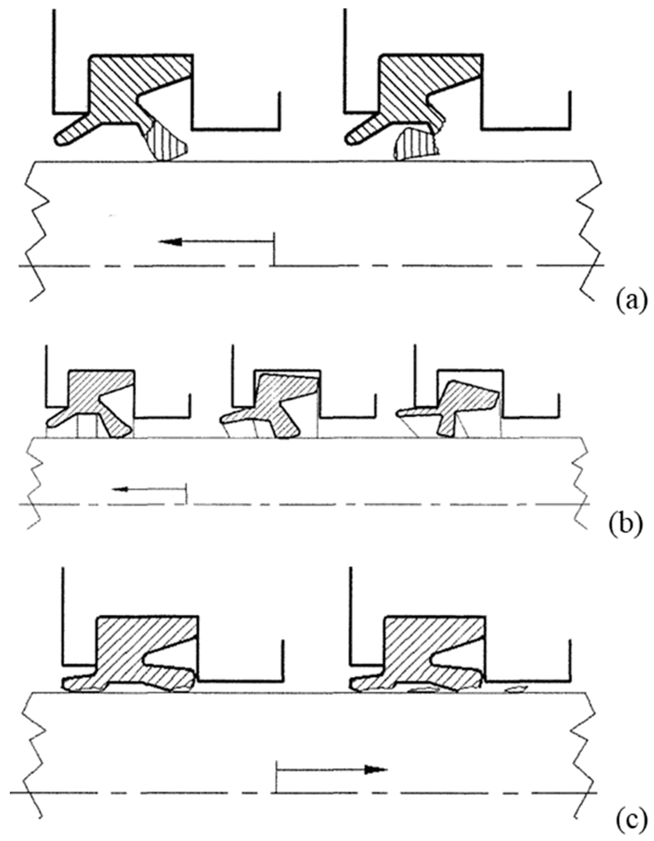
The fundamental failure modes that were observed during the tests are summarised and schematised in Figure 6: tearing of the lip (mode I—Figure 6a); complete or partial breakage of the seal due to extrusion or spiralisation (mode II—Figure 6b); wearing out of the contact region between the lip and the rod with the generation of debris due to adhesion and abrasion (mode III—Figure 6c).
Tearing of the lip is more often observed in the areas where the lip loses contact with the rod. This may happen if the clearance between the sealing element and the rod increases compared with the nominal condition as a result of excessive eccentricity. Bulk failure of the seal due to spiralisation or extrusion usually occurs as the diameter d 1   of the seat shoulder increases. Adhesion–abrasion of the elastomeric material of the lip produces a reduction in the thickness of the sealing lip and is identified by small cracks and signs of delamination at the edge of the lip.
In the following, the seal average lifetime is presented, highlighting key differences in endurance and wear resistance in relation to the seal cross-section shape and geometric tested variables; moreover, the failure modes that occurred most frequently for each individual seal type are presented.

3.1. Seal Type A1

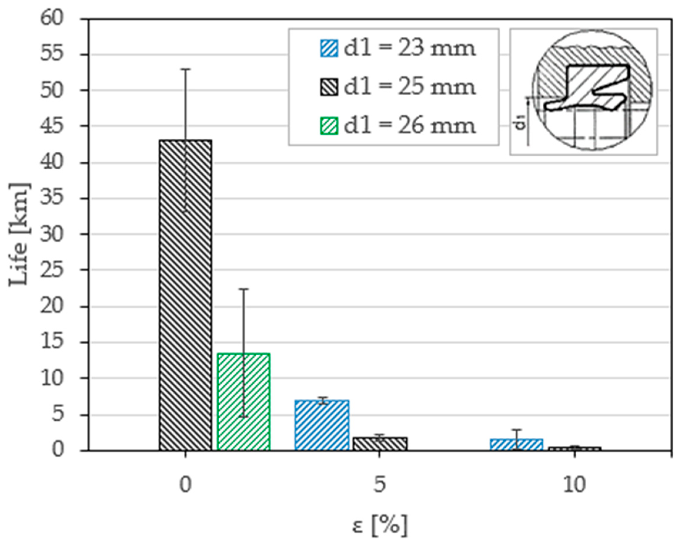
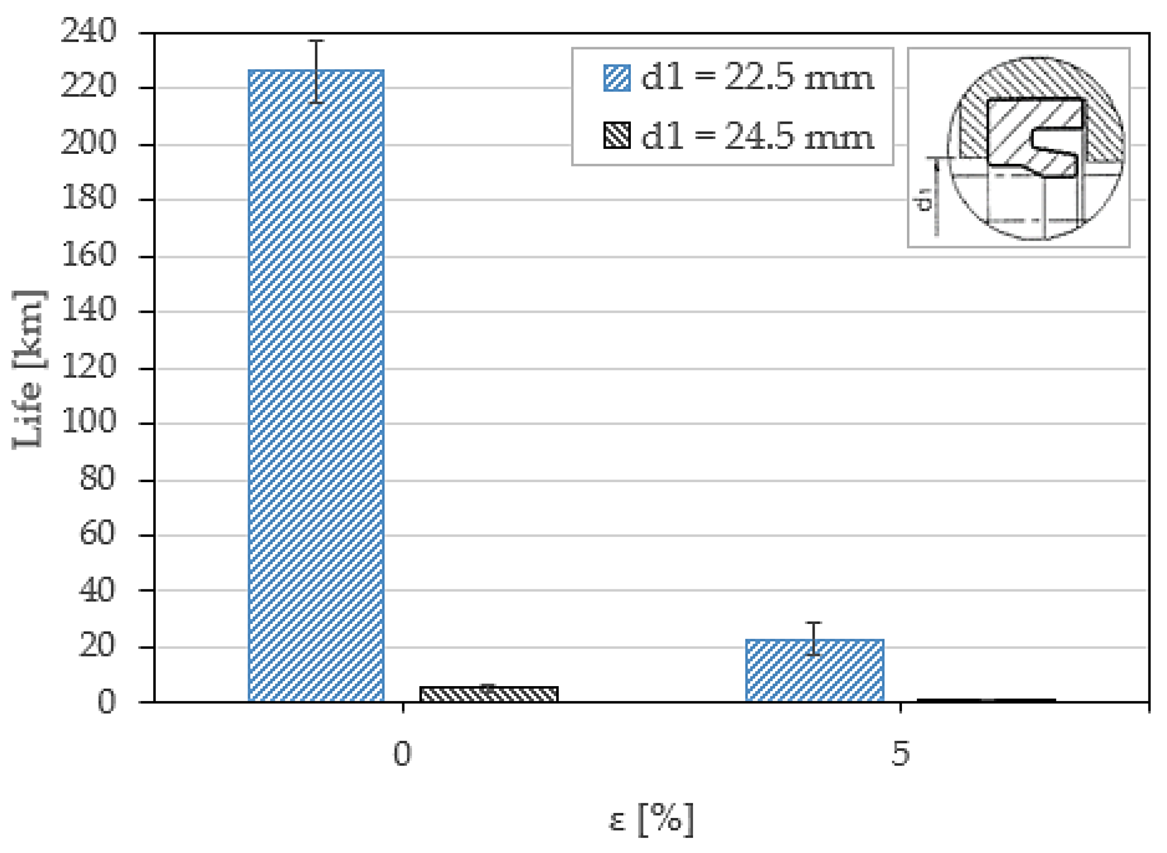
Figure 7 shows how the life of lip A1 seals is affected by the eccentricity e   and the diameter d 1 of the shoulder. The performance decreases significantly as the magnitude of both parameters increases. In general, this type of seal is not able to operate properly if its seat is machined differently with respect to the nominal dimension suggested by the seal manufacturer, and it poorly withstands lopsided radial forces. Failure mode I is the dominant mode when eccentricity is high and diameter d 1 is close to its nominal value, whereas mode II dominates as the shoulder diameter is increased, whatever the eccentricity value.
The results of Figure 7 predicted that the lifetime duration with null eccentricity and a nominal value of diameter d1 could be very long (test time of several weeks). Being this an overly long time for a large set of experimental tests, as here considered in this study, the condition d1 = 23 mm and e = 0 mm were not investigated.

3.2. Seal Type A2

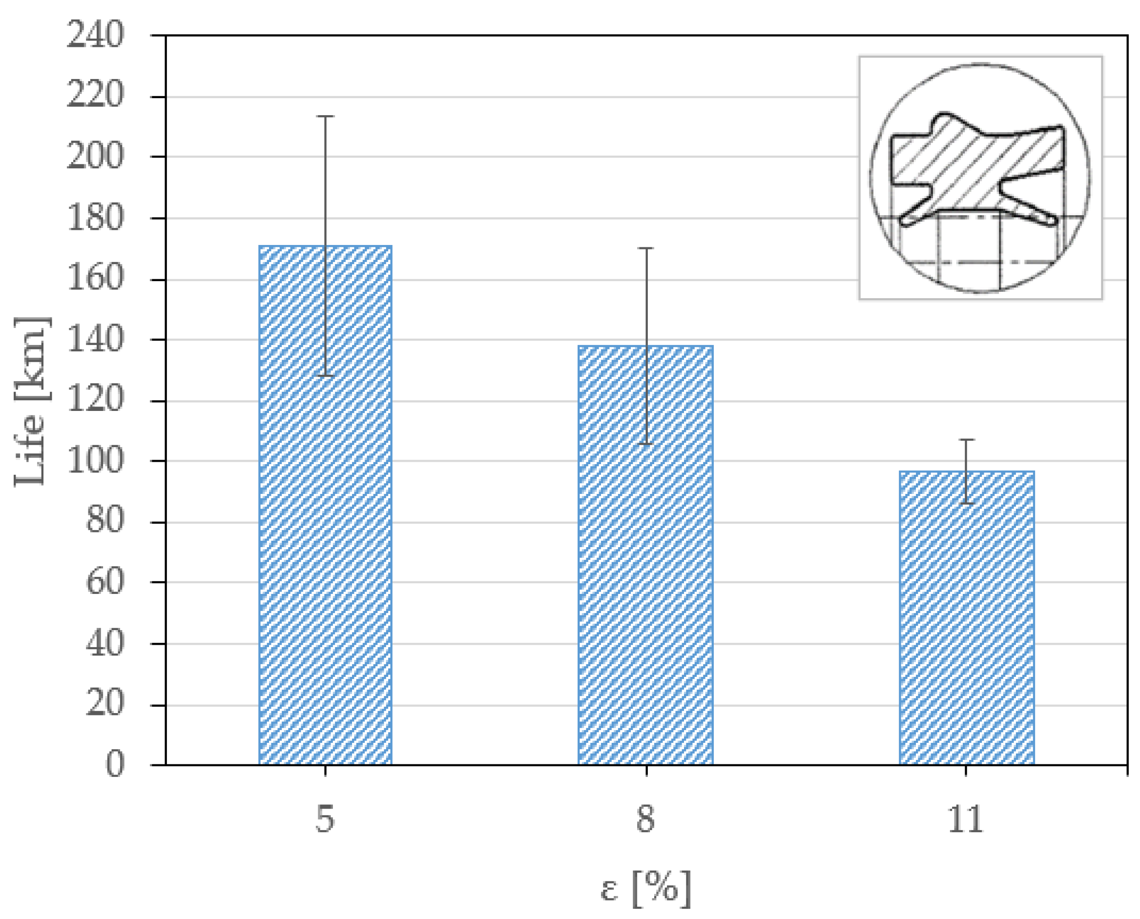
Figure 8 shows the estimated life of A2 seals as a function of the mounting eccentricity. These seals showed very long endurance, even under critical working conditions. No extrusion problems (mode II failure) were detected. High strength is due to both the squat shape of the section and the presence of the locking ridge that prevents any axial movement of the seal and provides high rotational stiffness to the section. The most frequently observed failure modes are modes I and III.

3.3. Seal Type A3

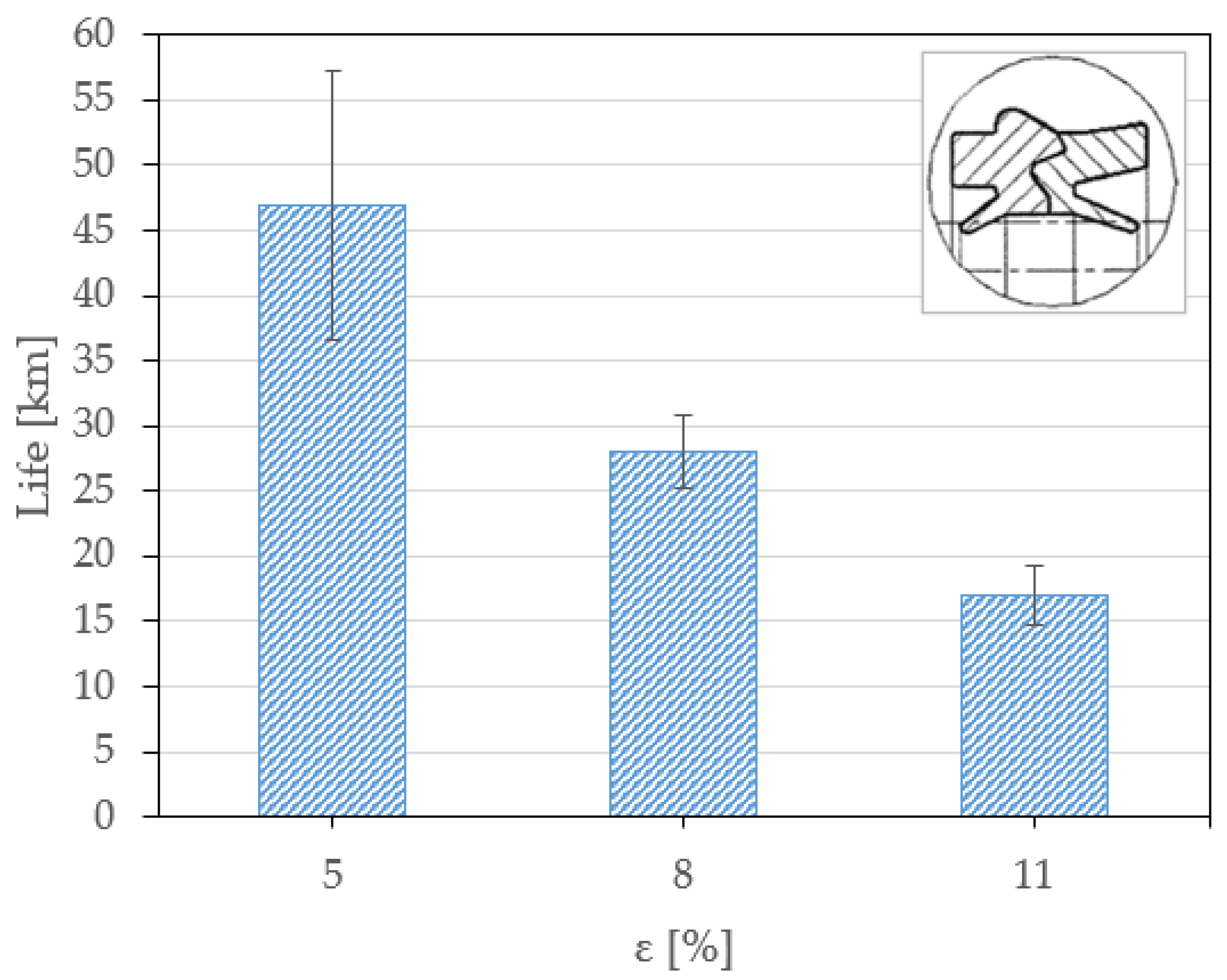
Figure 9 shows the estimated life of A3 seals. Compared with type A2, the life of these sealing elements is shorter when loaded through the same eccentricity value. Since A2 and A3 seals have the same geometry, the problem is related to materials. Polyurethane demonstrated its higher wear resistance with respect to NBR. Failure is typically from wear damages (failure mode III), where no case of seal extrusion was detected.

3.4. Seal Type B1

The estimated life of B1 seals is shown in Figure 10. Because B1 seals are the only ones without a rod scraper, a direct comparison with previous seal models is not possible. However, the service life of B1 seals is comparable to that of A1 seals, the latter having similar overall dimensions and the same material. As in the case of A1 seals, B1 showed an abrupt decrease in life with increased eccentricity.
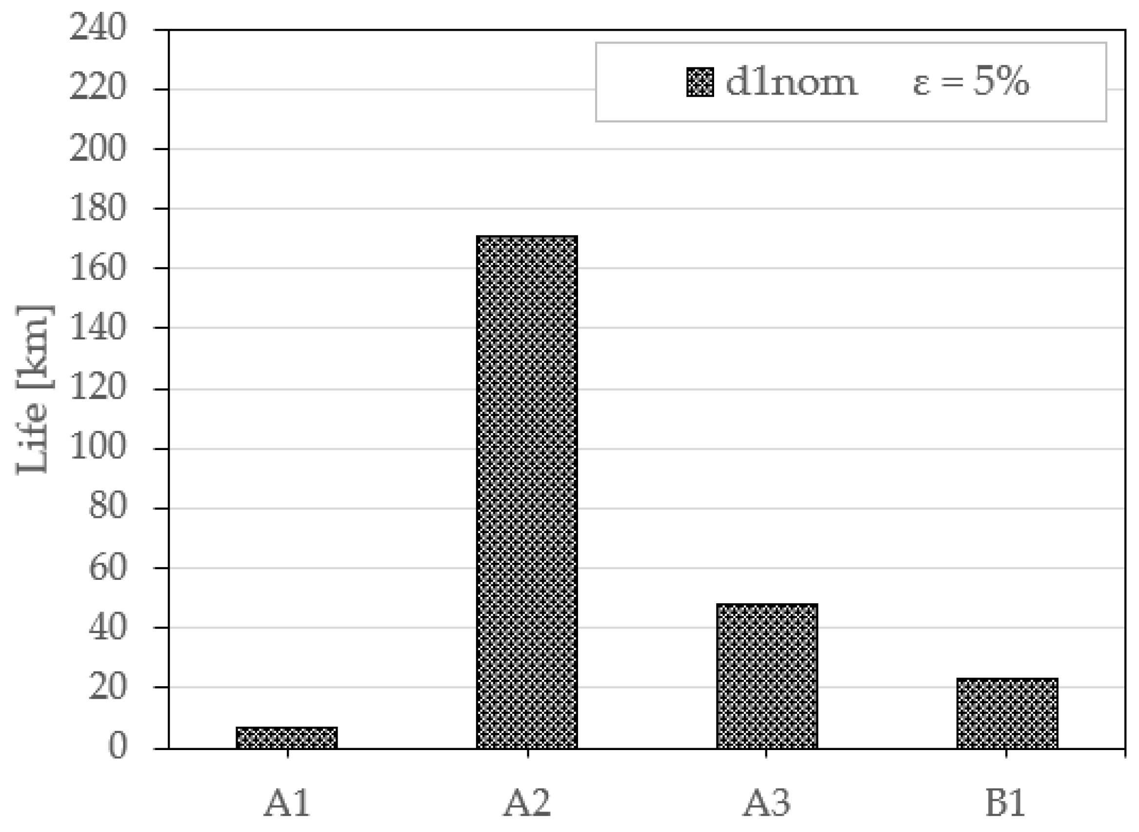
By way of comparison, Figure 11 shows the average experimental lifetime measured for seal types A1, A2 A3 and B1 when the shoulder diameter is the nominal value suggested by the seal manufacturer and the operational eccentricity during the tests is 5%.
A2 seals are the toughest, as they showed the highest wear resistance thanks to the high-performance material (EU) coupled with the increased mechanical strength against tearing and spiralisation provided by the stiffer cross-section. The key role of the material is highlighted in comparison with the A3 seals, whose average estimated life is three times lower than seal A2 while keeping the same cross-sectional geometry and overall dimensions.
The comparison between seals A3 and A1 indicates that the cross-sectional geometry plays a non-negligible role as well for the same material (NBR). The denser and squatter section of seal A3 positively affects the seal life, which is five times higher compared with A1 seals under a 5% eccentricity.
Among NBR seals, B1 seals also performed better than A1, and their life was, on average, 2.5 times higher under a 5% eccentricity and a nominal diameter of the shoulder. This effect is even larger if one compares the results obtained when the seal is retained by a nominal shoulder diameter d 1 , n o m and operated under null eccentricity, where the average life of seal B1 was approximately 5.5 times higher than seal A1 (see Figure 7 and Figure 10). In other test conditions, e.g., null eccentricity and seat diameter larger than the nominal, the lifetimes are similar.

4. Discussion

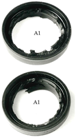
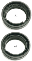
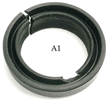
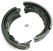
Fault analysis was carried out by observing the state of the seals under tests corresponding to the time when a fault was detected by a leakage test. This made it possible to outline a failure atlas of the most significant failure scenarios, reported in Table 3, which involves one or more fundamental failure modes (the latter being defined and schematised in Figure 6). The aim of the atlas is to make available a broad visual case history of damages and failures that seals may incur under operating conditions. A description is associated with each damage, taking care to relate the damages and failures to the test conditions and, in particular, the geometric test variables (eccentricity, shoulder diameter). The importance of the test variables in determining the failure modes will help the end user in a proper selection of the admissible limit of geometric variations, seal cross-section shape and materials.
The important role of the test variables in the occurrence of the above failure modes was clearly shown. In particular, the cross-sections A2 and A3, with higher stiffness and ridge/groove coupling, showed the highest lifetime and best resistance to spiralisation and extrusion from the mounting seat; the prevalent failure and damage was the thinning of the lip and cracks caused by wear abrasion. Material impacts seal performance a great deal; indeed, for the same cross-section shape, EU seals (A2) can last three times longer than NBR seals (A3). On the other hand, a dense and squat cross-section, both with a rod scraper (A3) and without it (B1), fosters a longer lifetime for the same seal material (NBR); for the same reason, A1 seals showed a lifetime 2.5 to 5 times lower than B1 and A3, respectively, for the same material (NBR) and eccentricity value.

5. Conclusions

The durability and failure modes of seals for linear pneumatic actuators were investigated in this work. To this end, a test bench was designed to perform endurance tests by replicating both operating conditions (pressurisation, linear reciprocating motion) and a variety of test variables, in particular, seal seat dimensions, misalignment of the rod with respect to the seal axis (eccentricity), seal cross-section shape and seal material were analysed. Severe operating conditions produced by eccentricity-induced wear, which reflected as an asymmetric load on the seal, were explored in the tests presented in this paper. Tests were carried out in dry conditions, thus allowing for an acceleration of the occurrence of seal failure and shorter endurance tests without loss of generality.
The key findings in terms of failure modes are tearing of the lip, complete or partial breakage of the sealing ring due to overextension and spiralisation of the ring and thinning of the lip due to abrasion and loss of chunks of material. The importance of the test variables (geometric, material and cross-section shape) in the occurrence of the failure mode and in the lifetime duration was demonstrated and explained. Although the measured lifetime durations do not give realistic indications of the actual life of seals for the relevant application, they show their importance for comparisons of seal behaviours. Fundamental failures were classified in a “Failure Atlas” in order to provide a useful collection of visual damages that the rod seals can incur; each type of damage was associated with the causes and operating conditions that led to it. Definitely, the atlas might be a helpful tool for the end user in proper seal selection, geometries, materials and mounting conditions that allow for acceptable behaviour without malfunctions as well.
Future development might be testing the seals in lubrication conditions to assess the influence of grease on seal performance and lifetime. The effect of grease on the failure modes should be minimal since the failure should occur after wear has produced the removal of grease and, thus, when dry conditions are established.

Author Contributions

Methodology, L.M.; Investigation, L.M.; Data curation, E.G.; Writing—original draft, L.M.; Writing—review & editing, L.M. and E.G.; Visualization, E.G.; Supervision, L.M.; Project administration, L.M. All authors have read and agreed to the published version of the manuscript.

Funding

This research received no external funding.

Data Availability Statement

The data presented in this study are available on request from the corresponding author.

Conflicts of Interest

The authors declare no conflicts of interest.

References

  1. Baart, P.; Lugt, P.M.; Prakash, B. Review of the lubrication, sealing, and pumping mechanisms in oil- and grease-lubricated radial lip seals. Proc. Inst. Mech. Eng. Part J J. Eng. Tribol. 2009, 223, 347–358. [Google Scholar] [CrossRef]
  2. Cuijpers, M.J.M. The sealing mechanism of lip seals for rotating shafts. Constructeur 1985, 224, 22–31. [Google Scholar]
  3. Burenin, V. New lip-type seals for sealing of rotating shafts. Russ. Eng. Res. 1997, 217, 89–93. [Google Scholar]
  4. Belforte, G.; Raparelli, T.; Mazza, L. Analysis of Typical Component Failure Situations for Pneumatic Cylinders Under Load. Lubr. Eng. 1992, 48, 840–845. [Google Scholar]
  5. C.N.O.M.O. 06.0700; Cahier des Charges de Reception et d’Homologation. CNOMO: Boulogne-Billancourt, France, 1968.
  6. C.N.O.M.O. E06.22.115.N; Verins Pneumatiques Controle Qualitatif. CNOMO: Boulogne-Billancourt, France, 1992.
  7. ISO 10099:2001; Pneumatic Fluid Power—Cylinders—Final Examination and Acceptance Criteria. ISO: Genève, Switzerland, 2001.
  8. ISO/TR 16194:2017; Pneumatic Fluid Power: Assessment of Component Reliability by Accelerated Life Testing. General Guidelines and Procedures. ISO: Genève, Switzerland, 2017.
  9. ISO 19973-1:2015; Pneumatic Fluid Power: Assessment of Component Reliability by Testing. Part 1: General Procedures. ISO: Genève, Switzerland, 2015.
  10. Belforte, G.; Manuello Bertetto, A.; Liu, S.; Mazza, L. Wear and Failure Analysis in Pneumatic Cylinders Under Radial Load. In Proceedings of the 11th International Sealing Conference, Dresden, Germany, 3–4 May 1999. [Google Scholar]
  11. Hobson, R. Leakage from Reciprocating Hydraulic Seals due to Solid Contamination. In Proceedings of the 15” International Conference on Fluid Sealing, Maastricht, The Netherlands, 16–18 September 1997; Halligan, B.D., Ed.; BHRA: Cranfield, UK, 1997. [Google Scholar]
  12. Chen, J.; Wu, Q.; Bai, G.; Ma, J.; Wang, Z. Accelerated Life Testing Design Based on Wear Failure Mechanism for Pneumatic Cylinders. In Proceedings of the 8th International Conference on Reliability, Maintainability and Safety, Chengdu, China, 20–24 July 2009. [Google Scholar]
  13. Chang, M.S.; Kwon, Y.I.; Kang, B.S. Design of reliability qualification test for pneumatic cylinders based on performance degradation data. J. Mech. Sci. Technol. 2014, 12, 4939–4945. [Google Scholar] [CrossRef]
  14. Belforte, G.; Raparelli, T.; Mazza, L. Life tests on elastomeric lip seals for pneumatic cylinders. Tribotest 1997, 3, 251–266. [Google Scholar] [CrossRef]
  15. Stolarski, T. Tribology in Machine Design; Butterworth Heinemann: Oxford, UK, 2000. [Google Scholar]
  16. Zum Gahr, K. Microstructure and Wear of Materials; Elsevier Science: Amsterdam, The Netherlands, 1987. [Google Scholar]
  17. Wassink, D.B.; Lenss, V.G.; Levitt, J.A.; Ludema, K.C. Phisically Based Modeling of Reciprocating Lip Seal Friction. J. Trib. 2001, 123, 404–412. [Google Scholar] [CrossRef]
  18. Debler, C.; Gronitzki, M.; Poll, G. Investigation into the Sealing Contacts of Reciprocating Elastomeric Seals—Correlation of Calculations with Contact Force Measurements and Optical Observations. In Proceedings of the 17th International Conference on Fluid Sealing, York, UK, 8–10 April 2003; Hoyes, J., Ed.; BHRA: Cranfield, UK, 2003. [Google Scholar]
  19. Lee, C.Y.; Lin, C.S.; Jian, R.Q.; Wen, C.Y. Simulation and experimentation of the contact width and pressure distribution of lip seals. Tribol. Int. 2006, 39, 915–920. [Google Scholar] [CrossRef]
  20. Belforte, G.; Conte, M.; Mazza, L. Low friction multi-lobed seal for pneumatic actuators. Wear 2014, 320, 7–15. [Google Scholar] [CrossRef]
  21. Qian, P.; Pu, C.; Liu, L.; Li, X.; Zhang, B.; Gu, Z.; Meng, D. Development of a new high-precision friction test platform and experimental study of friction characteristics for pneumatic cylinders. Meas. Sci. Technol. 2022, 33, 065001. [Google Scholar] [CrossRef]
  22. Juoksukangas, J.; Lehtovaara, A.; Miettinen, J.; Tolvanen, P.; Järvelä, P.; Niemi, A.M. Development of a test rig for reciprocating seals in heavy load condition. In Proceedings of the Nordtrib Conference, Storforsen, Sweden, 8–11 June 2010. [Google Scholar]
  23. Neale, M.; Gee, M. Wear Problems and Testing for Industry; William Andrew Publishing: Norwich, UK, 2001. [Google Scholar]
  24. Calvert, C.; Tirovic, M.; Stolarsk, T. Design and development of an elastomer-based pneumatic seal using finite element analysis. Proc. Inst. Mech. Eng. Part J J. Eng. Tribol. 2002, 216, 127–138. [Google Scholar] [CrossRef]
  25. Belforte, G.; Conte, M.; Manuello, A.; Mazza, L. Performance and Behavior of Seals for Pneumatic Spool Valves. Tribol. Trans. 2010, 54, 237–246. [Google Scholar] [CrossRef]
  26. Barillas, G.; Wangenheim, M.; Kinsch, P.; Jäckel, J. The T-Ring Principle: A sophisticated approach of sealing dynamically. In Proceedings of the 5th World Tribology Congress, Torino, Italy, 8–13 September 2013. [Google Scholar]
  27. Raparelli, T.; Mazza, L.; Trivella, A. Experimental analysis and preliminary model of non-conventional lip seals. Tribol. Int. 2023, 181, 108311. [Google Scholar] [CrossRef]
  28. Mokhtar, M.; Mohamed, M.; El-Giddawy, M.; Yassen, S. On the effect of misalignment on the performance of U-type lip seal. Wear 1998, 223, 139–142. [Google Scholar] [CrossRef]
  29. Pinedo, B.; Aguirrebeitia, J.; Conte, M.; Igartua, A. Tridimensional eccentricity model of a rod lip seal. Tribol. Int. 2014, 78, 68–74. [Google Scholar] [CrossRef]
  30. Bekgulyan, S.; Feldmeth, S.; Bauer, F. Influence of static and dynamic eccentricity on the pumping rate of radial lip seals. In Proceedings of the 25th International Conference on Fluid Sealing, Manchester, UK, 4–5 March 2020. [Google Scholar]
  31. ISO 15243:2017; Rolling Bearings—Damage and Failures. ISO: Genève, Switzerland, 2017.
  32. Gear Failure Atlas—Manual; AGMA: Alexandria, VA, USA, 2020.
  33. ISO 10825-1:2022; Gears—Wear and Damage to Gear Teeth—Part 1: Nomenclature and Characteristics. ISO: Genève, Switzerland, 2022.
  34. Merkle, L.; Baumann, M.; Bauer, F. Influence of alternating temperature levels on the wear behavior of radial lip seals: Test rig design and wear analysis. Appl. Eng. Lett. 2021, 6, 111–123. [Google Scholar] [CrossRef]
  35. Straffelini, G. Friction and Wear. Springer: Berlin/Heidelberg, Germany, 2015. [Google Scholar]
  36. Stachowiak, G.; Batchelor, A. Engineering Tribology, 4th ed.; Butterworth-Heinemann: Oxford, UK, 2013. [Google Scholar]
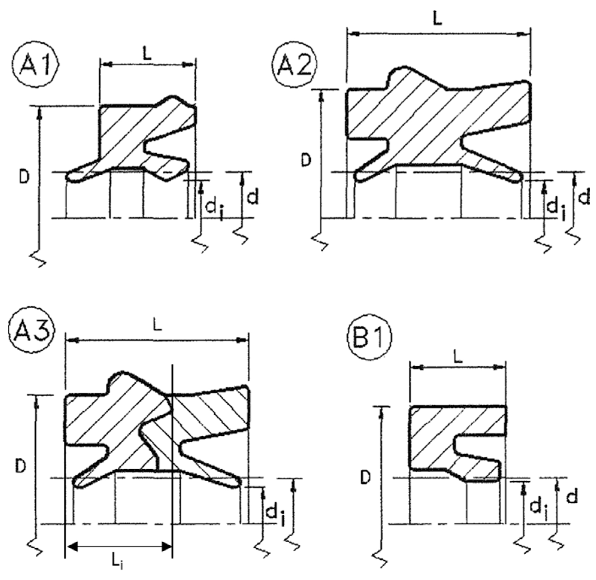
Figure 1. Cross-section schematics of the lip seals used for the experimental tests.
Lubricants 12 00119 g001
Figure 2. Examples of the mounting of lip seals into its seat in a pneumatic cylinder, with open seat and fixing rubber ridge (left side) and grooved seat (right side).
Lubricants 12 00119 g002
Figure 3. Schematic of the test bench designed for the endurance tests.
Lubricants 12 00119 g003
Figure 4. Section view of the test chamber: (a) comparison of the relative position between the rod and the test chamber after an eccentricity offset is applied; (b) enlarged detail with eccentricity mounting.
Lubricants 12 00119 g004
Figure 5. A typical leakage test repeated across the duration of an endurance test.
Lubricants 12 00119 g005
Figure 6. Fundamental failure modes of rod lip seal identified at the end of the endurance tests: (a) mode I: tearing of the lip; (b) mode II: seal extrusion or spiralisation, (c) mode III: adhesive–abrasive wear damages.
Lubricants 12 00119 g006
Figure 7. Lifetime for seal type A1 due to increased eccentricity and increased diameter d1 of the seat shoulder.
Lubricants 12 00119 g007
Figure 8. Lifetime for seal type A2 due to increased eccentricity.
Lubricants 12 00119 g008
Figure 9. Lifetime for seal type A3 due to increased eccentricity.
Lubricants 12 00119 g009
Figure 10. Lifetime for seal type B1 due to increased eccentricity and increased diameter d1 of the seat shoulder.
Lubricants 12 00119 g010
Figure 11. Lifetime comparison with nominal value d 1   n o m of the shoulder and eccentricity of 5%.
Lubricants 12 00119 g011
Table 1. Main characteristics of the seals under test.
TypeMaterialHardness (IRHD)Dimensions (mm)
dDLLi
A1Nitrile rubber7520305.5-
A2Polyurethane90203010.5-
A3Nitrile rubber +
Acetal resin
802030115.5
B1Nitrile rubber7820307.5-
Table 2. Range of variation in the geometric test variables.
Typed (mm)d1,nom (mm)Δd1 (%)e (mm)ε (%)
A120230, 8, and 130 to 10 to 10
A220--0.5 to 1.15 to 11
A320--0.4 to 14 to 10
B12022,50 and 70 to 0.50 to 5
Table 3. Atlas of most significant failure scenarios. In the description of the failure scenarios, lips are indicated as either the sealing lip or the rod scraper lip.
PictureDescriptionDominant Failure Mode
Lubricants 12 00119 i001Serious distributed loss of chunks of material from the sealing edge of lips (sometimes followed by tearing of the whole lip) due to operation under high mounting eccentricity.Mode I
Lubricants 12 00119 i002aLubricants 12 00119 i002bBulk continuous tearing of the sealing edge of the lip due to partial extrusion from the seat associated with a reduced retaining action of the shoulder (due to an increase in the diameter d1 of the seat shoulder). Sometimes, the lip detachment occurs without complete loss of material from the contact site.
Failure often indicates the region where extrusion took place during the tests, and cross-section distortion of the seal during wear cycles may also be experienced in these regions.
Mode II
and
Mode I
Lubricants 12 00119 i003Cracking of the sealing ring produced by a radial cut due to the complete ejection of the seal from its seat.Mode II
Lubricants 12 00119 i004Catastrophic failure with tearing of the lips followed by eventual cracking of the sealing body in two or more parts. It is associated with extreme cases where the ejection of the seal from its seat occurs under very high eccentricity coupled with a large diameter d1 of the retaining shoulder.Mode II
and
Mode I
Lubricants 12 00119 i005aLubricants 12 00119 i005bWearing out of the lip edge sliding against the steel rod is associated with the thinning of the lip and formation of jagged edges in the mostly loaded region of the seals (where the compression action of the rod, due to the eccentricity mounting, is greatest). Circumferential cracks may appear in the seal region where the compression against the rod is lower, and the lip tends to detach from the rod.Mode III
(Abrasion)
Lubricants 12 00119 i006Weakening of the lip section as a result of thinning may be so extended, and some portions of the sealing ring may be torn off by sticking and ejected.Mode III
(Adhesion–abrasion)
Lubricants 12 00119 i007aLubricants 12 00119 i007bDuring wearing out of the lip, some portions of the sealing edge may be ejected due to adhesive effects in the region where the eccentricity is maximum.Mode III
(Adhesion)
Lubricants 12 00119 i008Eccentricity misalignment of the rod reflected as thinning of the lip, which may produce a brittle failure of the sealing edge, and axial cracks may be observed in the region where the rod abraded the most.Mode III
(Abrasion)
and cracking
Lubricants 12 00119 i009Wearing out may develop as plastic deformation of the lip followed by thinning. Residual compression set is observed when the seal is taken out of its seat.Mode III
(Abrasion)
and plastic deformation
Disclaimer/Publisher’s Note: The statements, opinions and data contained in all publications are solely those of the individual author(s) and contributor(s) and not of MDPI and/or the editor(s). MDPI and/or the editor(s) disclaim responsibility for any injury to people or property resulting from any ideas, methods, instructions or products referred to in the content.