Abstract
Misalignments are unavoidable in most applications of the planetary roller screw mechanism (PRSM) due to many potential causes. However, the effect of screw misalignments on the contact characteristics for the PRSM have not been thoroughly investigated. In this paper, a comprehensive analytical procedure for the PRSM performance considering screw misalignments is proposed. First, the contact positions and clearances of the PRSM with screw misalignments are calculated. Next, an improved model is presented for evaluation of the load distribution, in which the variation of axial clearances is taken into consideration. The numerical results are validated by finite element analysis. Then, the precision loss model caused by wear is derived considering the variation of contact forces. The results indicate that the contact positions slightly change due to the misalignment angle of the screw, while the axial clearances and load distribution at the screw-roller interface are significantly affected. At the same time, the contact forces over thread vary periodically. In addition, the screw misalignment aggravates the wear of the PRSM, resulting in accuracy degradation. The theoretical investigations lay the foundation for the engineering application of the PRSM.
1. Introduction
The planetary roller screw mechanism (PRSM) has been widely applied in modern transmission systems because of its excellent features [1,2]. In practice, the performance features could be decreased due to the misalignment errors. These errors, especially screw misalignments, are unavoidable due to shaft deflection, initial assembly error and part geometry imperfection. The misalignment angle and offset vector errors of the PRSM are common in the course of engineering applications. However, the effect of screw misalignments on performance investigations of the PRSM was almost ignored in the past.
A great deal of research has been devoted to performance evaluations. The evaluations of contact positions and load distribution play crucial roles in the design of the PRSM, which paves the way for the analyses of friction [3,4,5], lubrication [6], dynamics [7,8,9,10], wear [11] and efficiency [12]. For contact positions, Jones et al. [13] established contact models based on the principle of the conjugate thread tooth surfaces, and evaluated the contact point positions and contact radii. Liu et al. [14,15] proposed an accurate model to calculate the contact trace distribution and contact positions and showed that the helical angle and vertex angle greatly affect the meshing performance. Fu et al. [16,17] presented a comprehensive contact analysis model with installation error and analyzed how the contact positions and clearances were affected by misalignments.
The misalignments of the PRSM changed the contact positions and clearances, which caused the variation of contact forces and contact ellipses. However, the previous works ignored the influence of misalignments. Du et al. [18,19] investigated the effect of the machining errors on the load distribution and revealed that the larger the absolute value of the negative error, the larger the axial clearance of the thread teeth, and the more obvious the change of the contact force distribution curve. Zhang et al. [20,21] proposed a model of the load distribution considering the pitch deviation, and redesigned roller thread teeth for improved load distribution consistency. Sandu et al. [22] proposed generalized equations to predict the contact ellipses over thread teeth.
The variation of contact forces and contact ellipses changed the wear of PRSM, whereas the influence of misalignment errors on the wear analysis of the PRSM was not considered. Aurégan et al. [23,24] revealed a quick adhesive wear in dry or bad lubricated conditions and showed that the effect of the input parameters on experiments were consistent with the theoretical calculation. Moreover, the wear of the ball screw was similar to the PRSM. Wei et al. [25] presented a new abrasion model based on the kinematic theory and revealed that the axial wear depth was determined by the wear depth of an asperity, contact ratio and wear frequency. Zhou et al. [26,27,28] presented the precision loss of the ball screw based on the modified Archard theory and showed the wear coefficient of the ball screw by experiments.
Based on the shortcomings mentioned above, a comprehensive analysis for the performance investigation of the PRSM with misalignments is proposed in this paper. First, in Section 2, the contact point positions and axial clearances of the PRSM are estimated by unloaded meshing equations of the thread tooth surfaces, and the modified model of load distribution with misalignment errors is derived by considering the variation of axial clearances and contact angles. Then, in Section 3, the contact positions, axial clearances, load distribution and wear caused by the effects of misalignment errors are elaborately analyzed. Finite element analysis (FEA) is utilized to validate the correctness of the revised load model. Finally, the conclusions are drawn in Section 4.
2. Mathematical Model
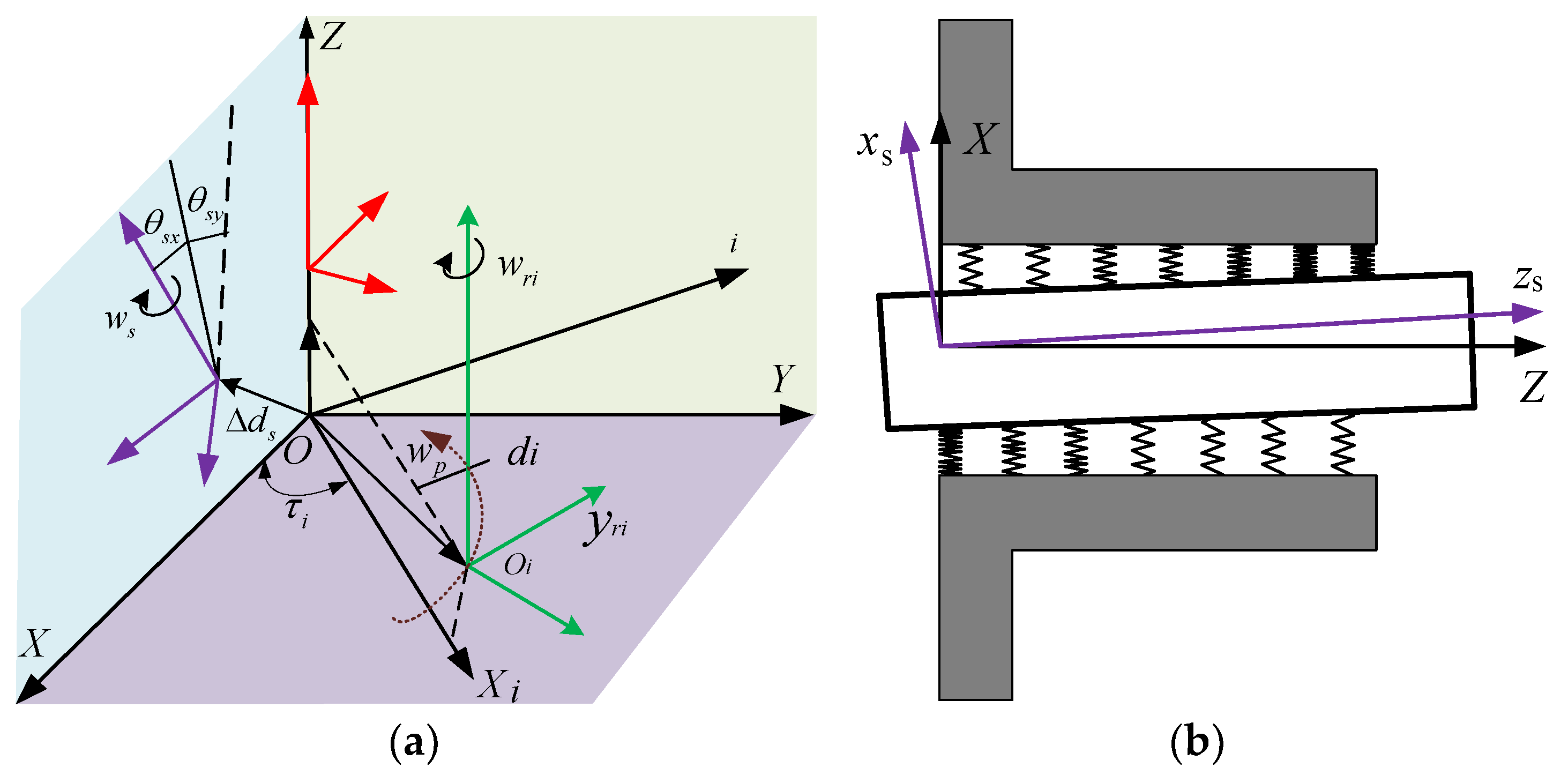
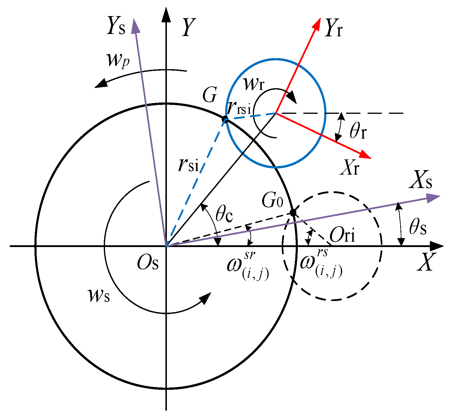
2.1. Coordinate Systems with Screw Misalignments
Figure 1 schematically shows the meshing principle of the PRSM with screw misalignments. As shown in Figure 1, the global coordinate system σ0(O: X, Y, Z) is fixed in space with its z-axis coincident with the axis of the screw without misalignments. The local coordinate systems σi(oi: Xi, Yi, Zi) are connected to the z axis of i# roller. Moreover, the local coordinate systems σs(os: xs, ys, zs), σri(ori: xri, yri, zri) and σn(on: xn, yn, zn) are rigidly connected to the axis line of misaligned screw and aligned roller and nut in space, respectively. θsx and θsy are the misalignment angle errors of the screw in the x and y directions, and Δds is the offset vector.
Figure 1.
Coordinate systems of the PRSM with screw misalignments. (a) Coordinate systems with screw misalignments. (b) Schematic diagram with screw misalignments.
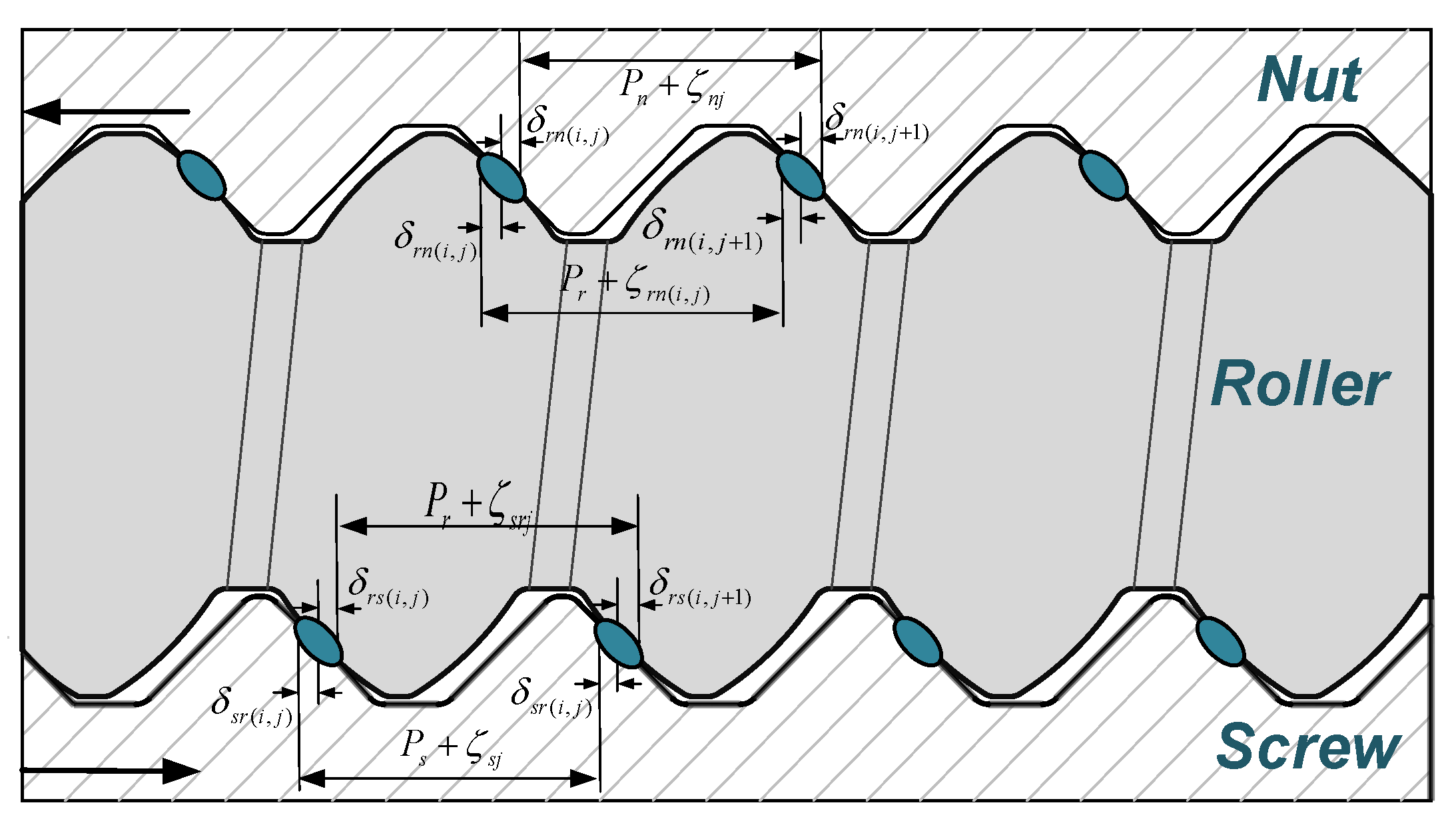
2.2. Contact Positions and Clearances at the Screw-Roller Interface
In the transmission process of PRSM, the two meshing surfaces must be in tangential contact at all times, which requires that the position vector and normal of the two surfaces at the meshing point are coincident at any instant. Therefore, when the two helical surfaces of the PRSM mesh, they will be in tangential contact, and the corresponding tangency equations can be expressed by [17]:
where,
is the thread tooth surface equation of the screw with screw misalignments,
is the thread tooth surface equation of the roller without errors,
is the vector of contact clearance in axial direction,
is the normal vector of the screw thread surface with screw misalignments,
is the normal vector of the m# roller thread surface without errors,
is the proportionality coefficient and equal to .
According to Figure 1a and [16], the thread tooth surface equation of the screw with misalignments can be calculated by:
where, Ts and are the coordinate transformation matrices and can be written by:
where τi is equal to 2π(i − 1)/n, and n is the total number of rollers.
and are the thread tooth surface equations of the screw and roller in the coordinate system σs(os: xs, ys, zs) and σri(ori: xri, yri, zri), and are given as:
where j is the thread number.
The normal vector and can be derived by:
where λs denotes the helix angle of the screw and λs = arctan(nsP/πds). λr is the helix angle of the roller and λr = arctan(P/πdr).
According to Equations (1)–(8), the contact positions and axial clearances at the screw-roller interface can be obtained by solving Equation (1).
2.3. Contact Positions and Clearances at the Roller-Nut Interface
Similarly, the thread tooth meshing equation can be expressed by:
where and are the thread tooth surface equations of the nut and roller in σn(on: xn, yn, zn) and σri(ori: xri, yri, zri), and are given as Equations (10) and (11). is the proportionality coefficient and equal to .
The normal vector and can be derived by:
According to Equations (9)–(12), the contact positions and axial clearances at the roller-nut interface can be obtained by solving Equation (9).
2.4. Calculation of Contact Forces
The load distribution can be calculated in accordance with the previously calculated axial clearances. In this study, the screw and nut are subjected to an axial tensile force and axial compressive force, respectively. The contact deformation of the PRSM is shown in Figure 2.
Figure 2.
PRSM deformation conditions of thread meshing section.
According to Figure 2, the deformation relation at the screw-roller interface can be written by:
Then, Equation (14) becomes:
where the axis deformation and at the screw-roller interface can be written by:
Hence, the axial stiffness of the screw and roller can be expressed by:
Suppose and are the axial force applied to the j-th thread of the i# roller by the screw and the nut, respectively.
According to the Hertz contact theory, the Hertz contact deformation at the screw-roller interface can be modeled by:
where is the Hertz contact stiffness of the screw-roller interface and can be calculated by:
where Ke is complete elliptic integral of the first kind. mas is the major semi-axis coefficient. is the curvature sum of the screw-roller interface.
From Equations (14)–(20), the recursive equation at the screw-roller interface with screw misalignments can be revised as:
Similarly, the recursive equation at the roller-nut interface with screw misalignments can be expressed as:
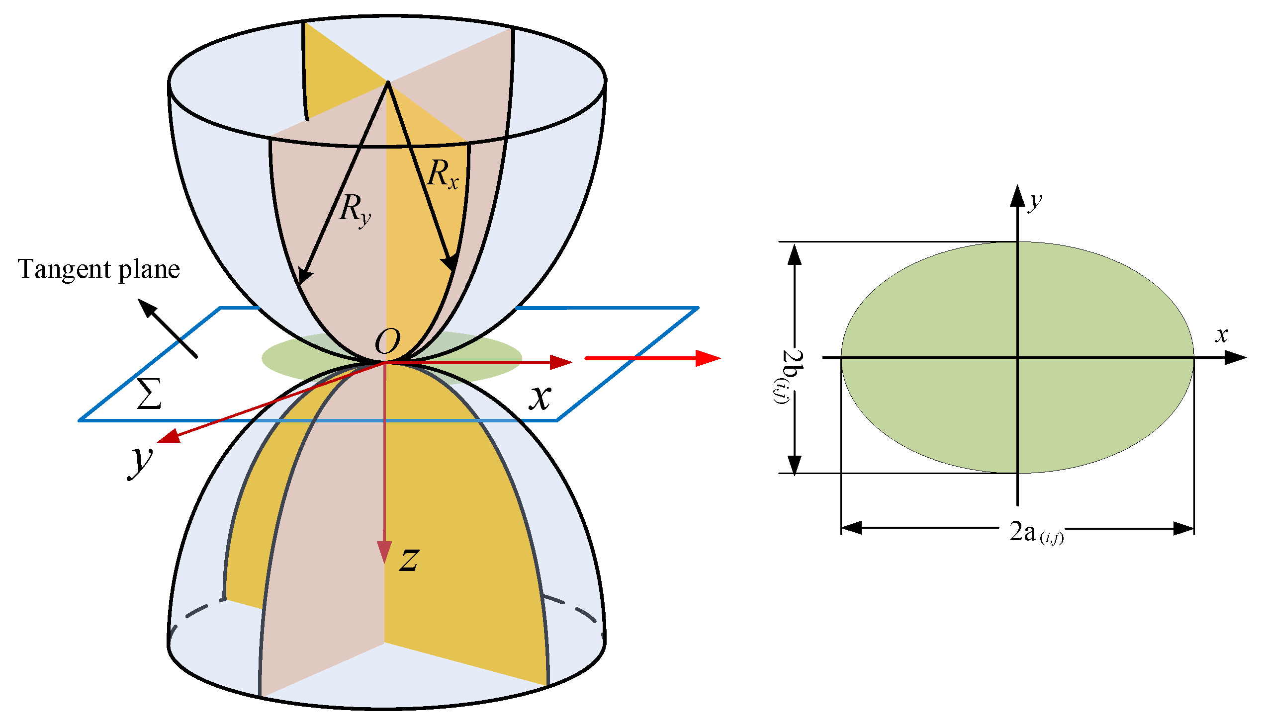
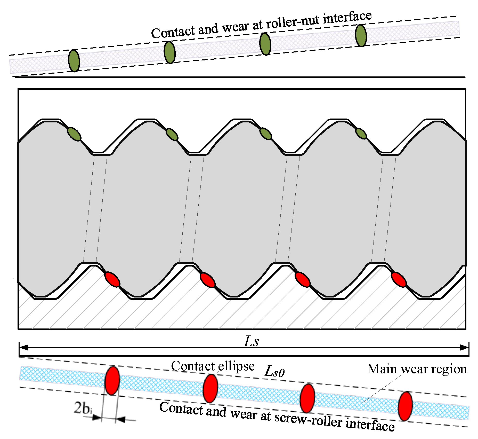
2.5. Calculation of the Contact Ellipses and Nominal Contact Area
As shown in Figure 3, the shape of the contact area at the screw-roller or roller-nut interfaces are an ellipse under normal contact load. The main curvature depends on the design parameters of the screw, roller and nut. The main curvature of the roller can be calculated by:
and the main curvature of the screw and nut can be expressed as:
where rr and rs are the nominal radii of the screw and roller, respectively. R is the radius of the effective ball of the roller and can be calculated by:
Figure 3.
A dynamic coordinate system of point contact.
According to [29], the semi-major and semi-minor axes at the screw-roller or roller-nut interfaces are expressed by:
The nominal contact area and at the screw-roller or roller-nut interfaces are written as:
2.6. Calculation of the Slip Velocity
In order to calculate the wear depth caused by the sliding between the screw and the roller, it is necessary to analyze the relative sliding speed at the meshing point of the roller and screw. Figure 4 shows the kinematic coordinate system of the PRSM at the screw-roller interface. As shown in Figure 4, at instantaneous contact point G, the velocity on the screw can be expressed by:
and the velocity on the roller can be written as:
where wp is the revolution speed and can be calculated by:
Figure 4.
The kinematic coordinate system of PRSM.2.7 Calculation of the wear volume and precision loss.
Hence, the sliding velocity at contact point G can be expressed by:
The magnitude of the sliding velocity can be expressed as:
The main wear mode of the PRSM is adhesive wear, which has been validated by experiments [24]. In this paper, the wear volume and precision loss are mainly calculated at the screw-roller interface, because the main contact mode at the screw-roller interface is sliding contact, whereas that at the roller-nut interface is rolling contact [4].
Figure 5 shows the contact and wear mechanism of the PRSM during operation. As shown in Figure 5, the shaded parts are the main wear region that may be considered as rectangular with a width of 2bi. According to the modified Archard wear theory [28], the amount of wear volume at the screw-roller interface under normal load can be written as:
where K is the wear factor that is closely related to the material, surface roughness, lubrication conditions and system load [30]. In this paper, K is equal to 3.3 × 10⁻⁷.
Figure 5.
Contact and wear mechanism of the PRSM during operation.2.8 Numerical implementation.
Combining Equations (26) and (33), the wear depth hw(i,j) at the screw-roller interface can be written as:
Thus, the total wear depth is expressed as:
As shown in Figure 6, the flowchart of the computational procedure implemented the mathematical model for the PRSM is graphically illustrated. The basic solution can be accomplished by the following main steps:
Figure 6.
Flowchart of computational procedure.
Step 1: According to the input parameters of the misaligned PRSM, the contact positions and axial clearances at the screw-roller and roller-nut interfaces are calculated by Equations (1) and (9). Moreover, the contact radii and meshing angles can be obtained.
Step 2: Judge whether the thread couples are loaded or not, establish the improved load equilibrium equation set considering axial clearances and solve it with the Newton–Raphson method for contact forces at the screw-roller and roller-nut interfaces.
Step 3: Calculate the size of contact ellipses in the normal direction considering the variation of contact forces.
Step 4: The sliding velocity at the contact point, G, can be defined by Equation (32).
Step 5: The wear volume and depth are obtained by the modified Archard wear theory where the contact forces, contact ellipses and sliding velocities with screw misalignments are taken into consideration, and the precision losses of PRSM caused by the wear are obtained.
3. Numerical Examples and Discussion
The influence of screw misalignments on the contact characteristics of the PRSM is investigated by the numerical examples. The material and design parameters are shown in Table 1 and Table 2. The parameters of screw misalignments for four different cases are shown in Table 3.
Table 1.
Material parameters of the PRSM.
Table 2.
Design parameters of the PRSM.
Table 3.
Parameters of screw misalignments.
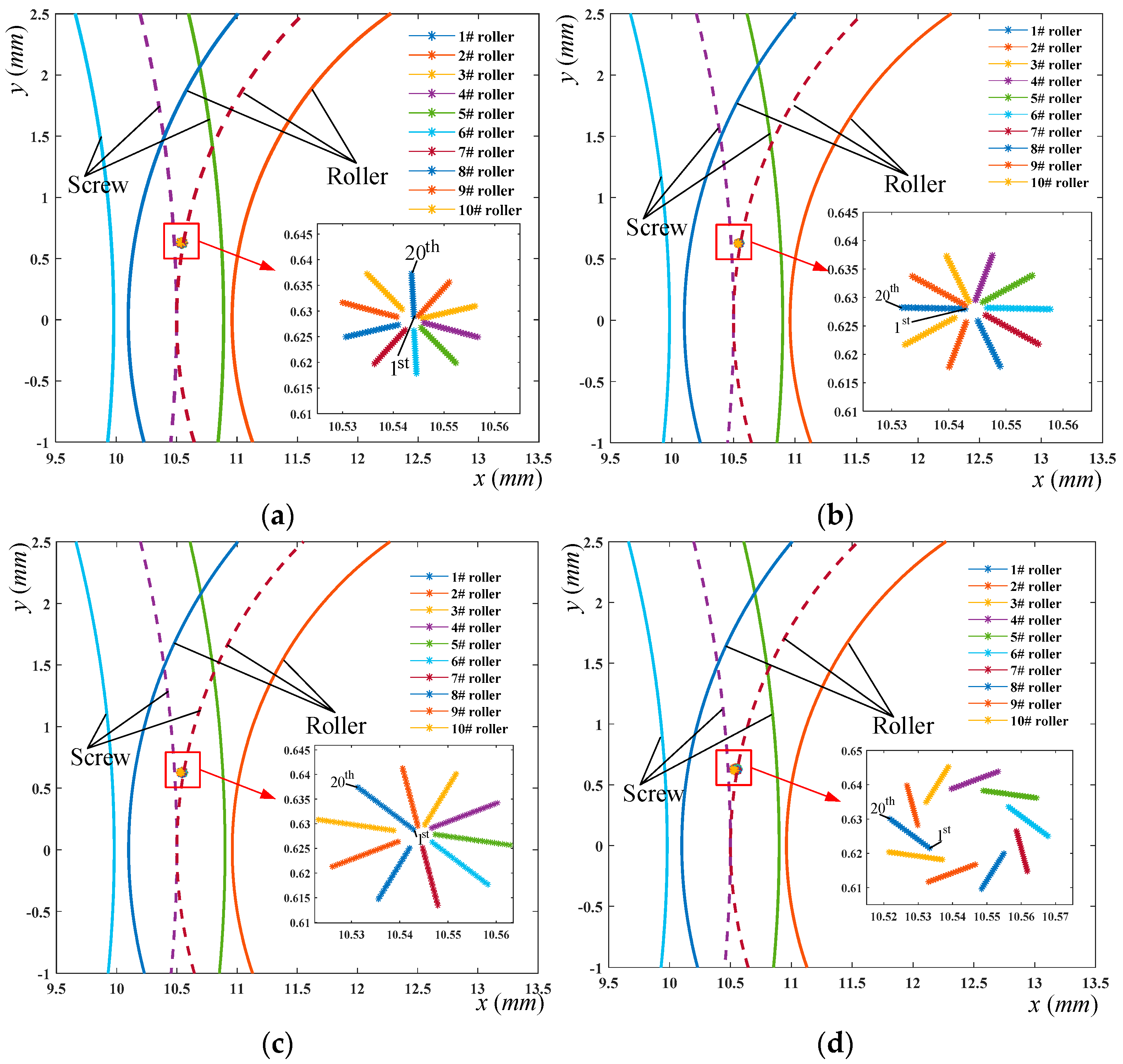
3.1. Effect of Misalignment on Contact Point Positions and Axial Clearances
When the screw is misaligned as shown in Figure 1b, some thread teeth of the roller will be close to the screw, while the other will be far from the screw. What is worse is that some thread teeth at the screw-roller interface may not contact. Figure 7 shows that the contact point positions of the mating thread surfaces on each pair of thread teeth along the axial direction are represented in four different cases, and those are calculated by Equation (1). It can be observed from Figure 7 that the contact point positions are always away from the center line connecting the screw and roller at the screw-roller interface. Moreover, the contact point positions of the 6# roller will be close to the line connecting the center of the roller and screw with the increase of the thread number, while the change tendency of the 1# roller is the opposite. The contact positions of the 2~5# rollers move toward the screw thread crest with the growth of the thread number, while those of the 6~10# rollers move toward the roller thread crest. This is consistent with [31]. Figure 7b shows the evolution of contact positions at the screw-roller interface for case 2, which corresponds to Figure 7a and the rollers order change. Then, comparing Figure 7c with Figure 7a,b, the contact positions are slightly closer to the screw or roller crest with the increase of the thread number when there are both x-direction and y-direction misalignment angle errors. Figure 7d shows that the contact point positions are more divergent when the offset vector is introduced for case 4. Therefore, the contact positions are susceptible to screw misalignments.
Figure 7.
Contact point positions at the screw-roller interface along axial direction in 4 different cases. (a) Case 1. (b) Case 2. (c) Case 3. (d) Case 4.
Figure 8 shows the effect of screw misalignments on axial clearances at the screw-roller interface. The axial clearances of the misaligned PRSM are represented by the full lines, while those of the aligned PRSM are denoted by the dotted lines. It can be notably found from Figure 8 that all axial clearances are 0.023 mm under aligned screw, while those with misalignments either increase or decrease with the increase of the thread number. Figure 8a shows the variation of axial clearances when the misalignment angle error θsx is 1 arcmin. For the 4# roller, the difference between the maximum value and minimum value is 10.9 μm and the axial clearances between adjacent threads are 0.57 μm. For other rollers, the axial clearances also change significantly. Figure 8b shows that the variation of axial clearances is similar to that of Figure 8a when the misalignment angle error θsy is 1 arcmin. Comparing Figure 8c with Figure 8a,b, the axial clearances vary more significantly when there are both x-direction and y-direction misalignment angle errors. The maximum axial clearance rises 12.12% from 0.033 mm to 0.037 mm, and the minimum axial clearance decreases 38.46% from 0.013 mm to 0.008 mm. Figure 8d shows the curves of the axial clearance are more divergent when the offset vector is introduced. However, compared with Figure 8c, under the same roller, the difference between the maximum and minimum clearances is equal and the difference between adjacent threads is also the same. Thus, it can be concluded that the axial clearances are sensitive to misalignment angle errors of the screw.
Figure 8.
Axial clearances of the mating thread surface in 4 different cases. (a) Case 1. (b) Case 2. (c) Case 3. (d) Case 4.
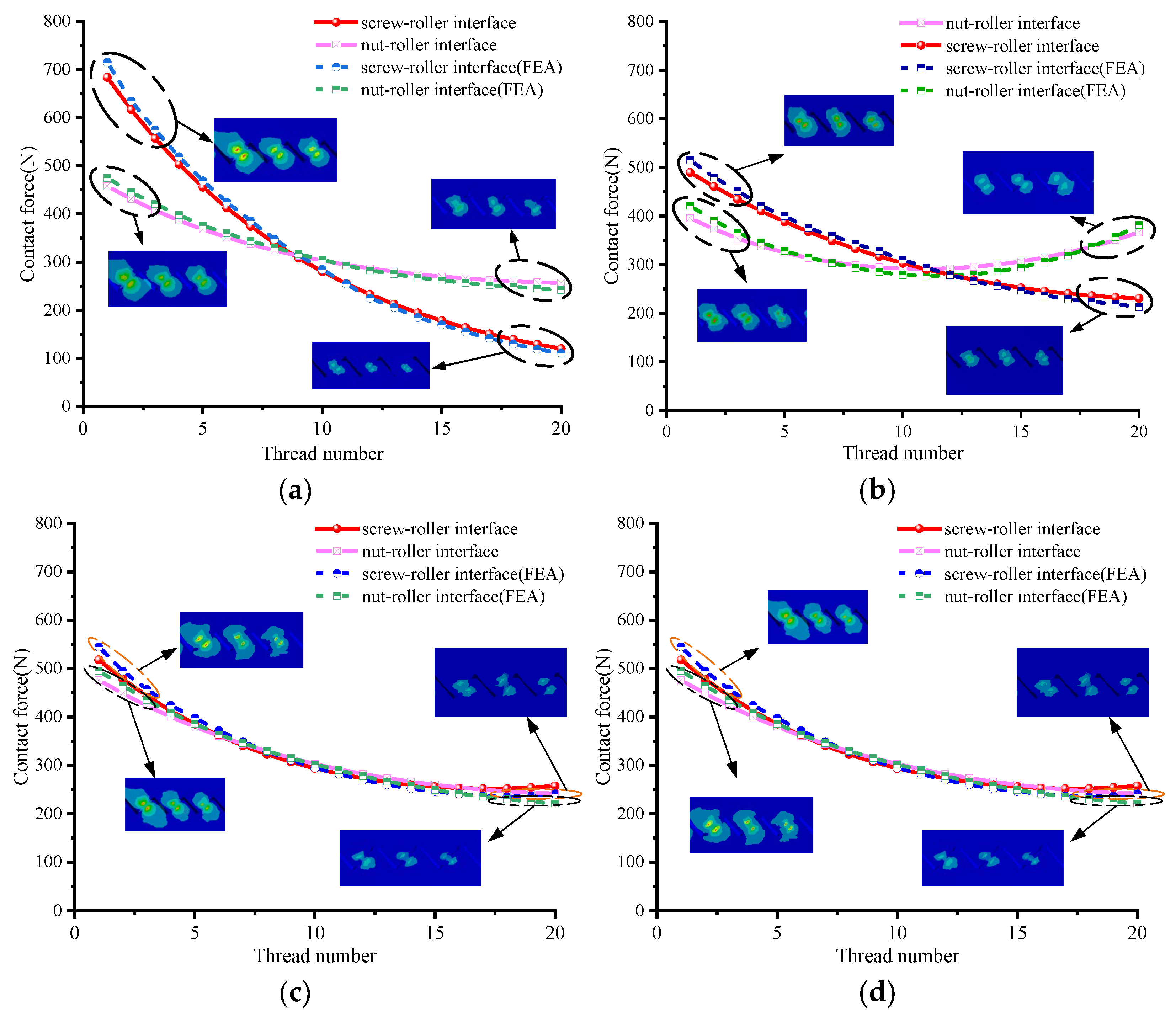
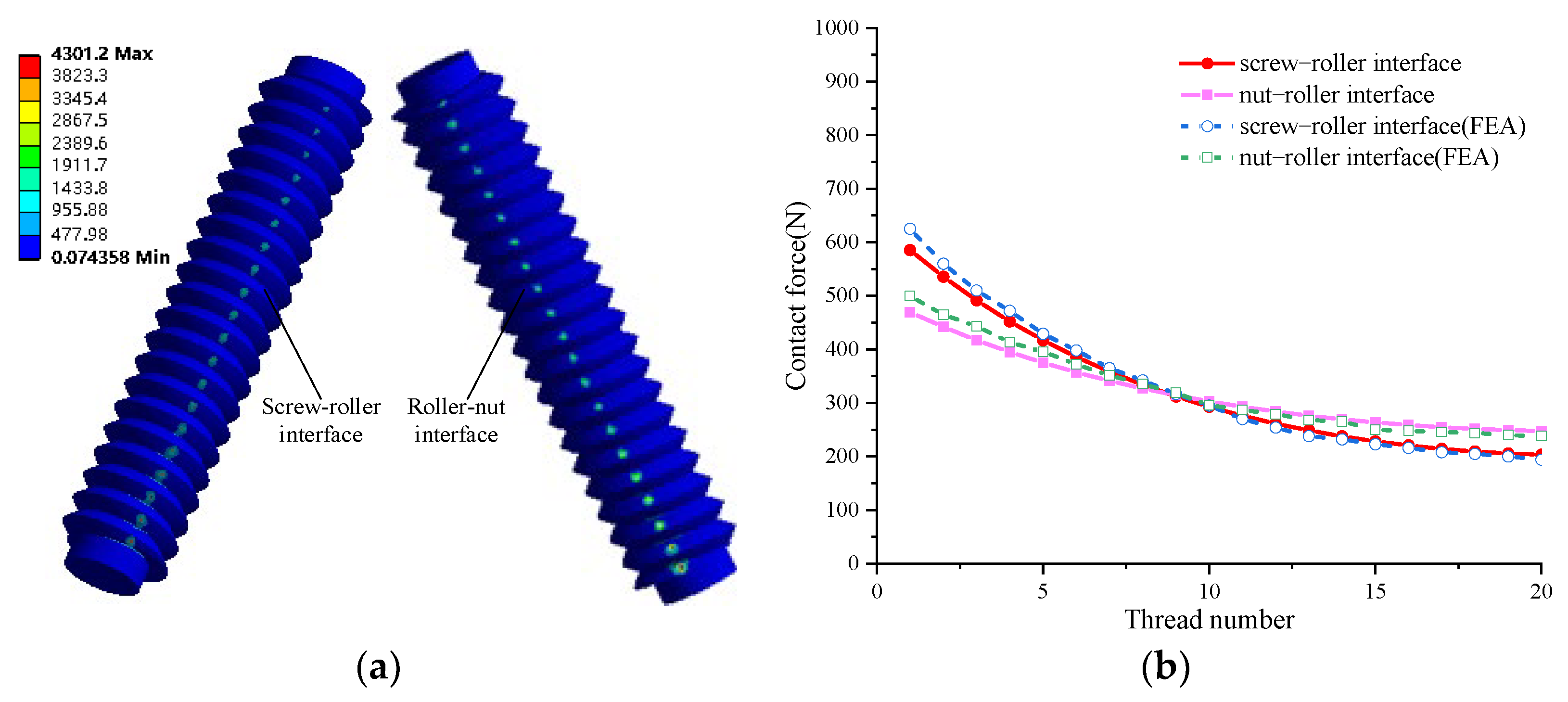
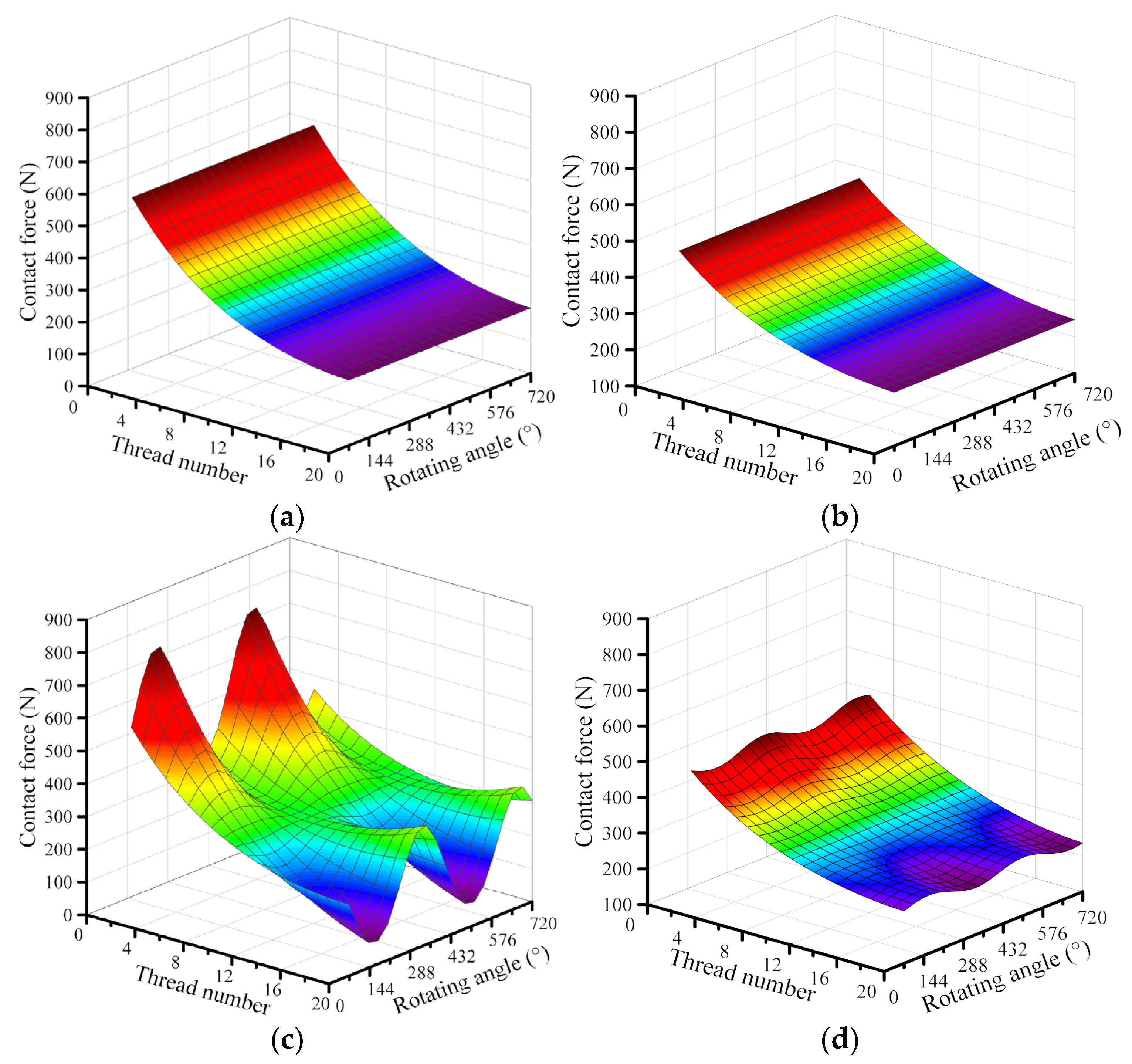
3.2. Effect of Misalignment on Load Distribution
The variation of axial clearances caused by the screw misalignments change contact forces. The influence of screw misalignments on load distribution is shown in Figure 9, and the contact forces at the screw-roller and roller-nut interfaces are represented by the full line and dotted line, respectively. It can be seen from Figure 9 that the screw misalignments significantly change the contact force curves at the screw-roller interface, while those slightly change the contact force curves at the roller-nut interface.
Figure 9.
Load distribution in 4 different assembly cases. (a) Standard assembly. (b) Case 1. (c) Case 3. (d) Case 4.
Figure 9a shows the load distribution against the thread number in the aligned assembly. It can be found that the non-uniformity of the load distribution at the screw-roller interface is greater than that at the roller-nut interface. The consistency with [20] indicates the correctness of the numerical model proposed in the present study. Then, Figure 9b–d show the load distribution against the thread number with the different misalignments. Comparing Figure 9b with Figure 9a, the contact force curves are not imposed at the screw-roller interface when the screw misalignments are θsx = 1 arcmin. The main reason is that the misalignment angle error in the x direction leads to the variation of contact point positions at the screw-roller interface so that the axial clearances change, as indicated in Figure 9a. In accordance with Equations (21) and (22), the contact forces change with the variation of the axial clearances. Moreover, the maximum contact force rises about 32.7% from 585.5 N to 777.2 N when the misalignment angle θsx changes from 0 arcmin to 1 arcmin. Comparing Figure 9c with Figure 9b, some curves of contact force become more uneven and others become more uniform at the screw-roller interface. The maximum contact force rises about 11.4% from 777.2 N to 865.8 N. Figure 9d displays the influence of the comprehensive errors on load distribution, which is consistent with Case 3. The main reason is that the thread deformations in the axial direction, including deformations caused by bending, shear, thread root lean, thread root shear and radial shrinkage (or expansion) [32], are ignored. Thus, it can be concluded that the screw misalignments increase the local contact forces, resulting in increased vibration, wear and reduced life.
In order to validate the proposed model of load distribution, the finite element method is carried out in different misalignments. As shown in Figure 10, the normal contact stresses decrease at the screw-roller and roller-nut interfaces with the growth of the thread number, and the stresses at the roller-nut interface are more uniform than those at the roller-nut interface. Then, Figure 11 shows the comparison of load distribution between the finite element results and the numerical calculation for the 2# roller in different misalignments. It can be found from Figure 11 that the contact forces by the proposed model are very similar to those provided by FEA, and the results of FEA are slightly more uneven than those of numerical calculation. As mentioned earlier, the proposed model ignores deformations other than Hertzian contact and axial compression deformations. To sum up, the analytical results are consistent with the simulation results; thus, the accuracy of the proposed model of load distribution is verified.
Figure 10.
Comparison of FEA and numerical results in standard assembly. (a) Stress distribution. (b) Numerical results and FEA results.
Figure 11.
Comparison of FEA and numerical results for 2# roller with 4 different assembly cases. (a) Standard assembly. (b) Case 1. (c) Case 3. (d) Case 4.
Figure 12 shows the aligned and misaligned PRSM subject to the load cycle of 720° are simulated. It can be found from Figure 12a that under the same thread number, the contact forces of the aligned PRSM are the same when the screw is rotating. However, as shown in Figure 12b, it is interesting to note that the contact forces at the screw-roller and roller-nut interfaces vary periodically when the misaligned angle θsx in the x-direction is 1 arcmin. The varied range at the screw-roller interface is much greater than that at the roller-nut interface. According to the calculated results, the contact force equation at any contact point over time can be expressed as:
Figure 12.
Load distribution of 1# roller for aligned assembly and case 1 in cycling process. (a) Aligned assembly at the screw-roller interface. (b) Aligned assembly at the roller-nut interface. (c) Misaligned assembly at the screw–roller interface. (d) Misaligned assembly at the roller-nut interface.
Hence, the contact forces with screw misalignments change periodically when the misaligned PRSM is in work.
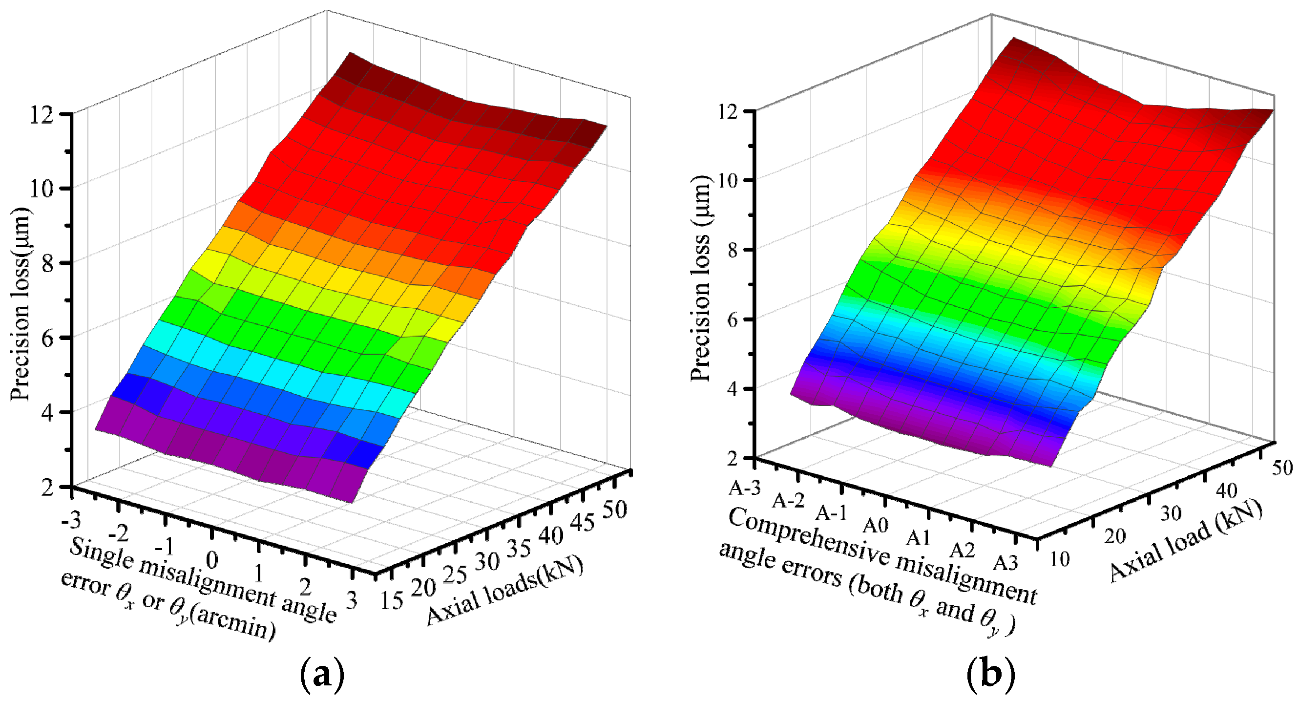
3.3. Effect of Misalignment on Wear and Precision Loss
Figure 13 shows the precision loss varying with misalignment errors and axial loads. It can be found from Figure 13a that the precision loss slightly increases with the growth of the misaligned angle θx or θy, and significantly increases with the growth of axial loads. Comparing Figure 13b with Figure 13a, under the same axial load, the total wear depth is more severe. When given an axial force of 50 kN, the total wear depth reduces by 7.53% from 11.52 μm to 10.65 μm when comprehensive misalignment errors (θsx, θsy) change from (−3 arcmin, −3 arcmin) to (0 arcmin, 0 arcmin). The total wear depth rises 8.83% from 10.65 μm to 11.59 μm when comprehensive misalignment errors (θsx, θsy) increase from (0 arcmin, 0 arcmin) to (3 arcmin, 3 arcmin). The comprehensive misalignment errors are listed in Table 4. Hence, it can be concluded that the screw misalignment aggravates the wear of the PRSM to a certain content, and the precision loss is more susceptible to comprehensive misalignment angle errors than a single misalignment angle error.
Figure 13.
Precision loss varying with misalignment angle errors and axial loads. (a) Single misalignment angle error. (b) Comprehensive misalignment angle error.
Table 4.
The errors with misalignment errors (unit arcmin).
4. Conclusions
This paper investigates the effect of screw misalignments on the performance of the PRSM. The tangency equations at the screw-roller and roller-nut interfaces are first established by considering the screw misalignments based on the spatial meshing principle. The improved model of load distribution is then derived to show that the model takes the variation of axial clearance into account. The precision loss caused by the wear is deduced in accordance with the modified Archard theory. The FEA is conducted to demonstrate the correctness of the model. The main results are as follows:
- (1)
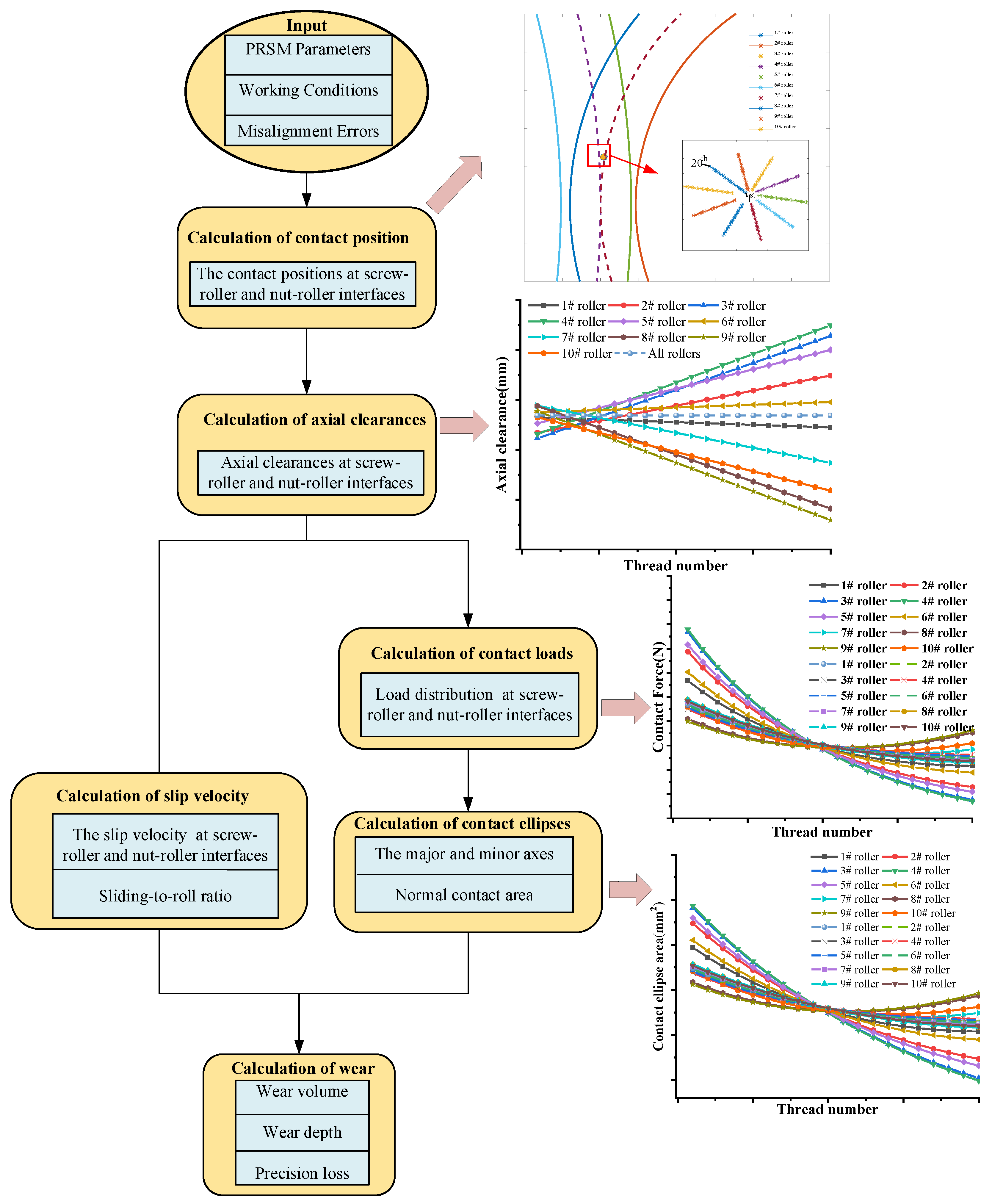
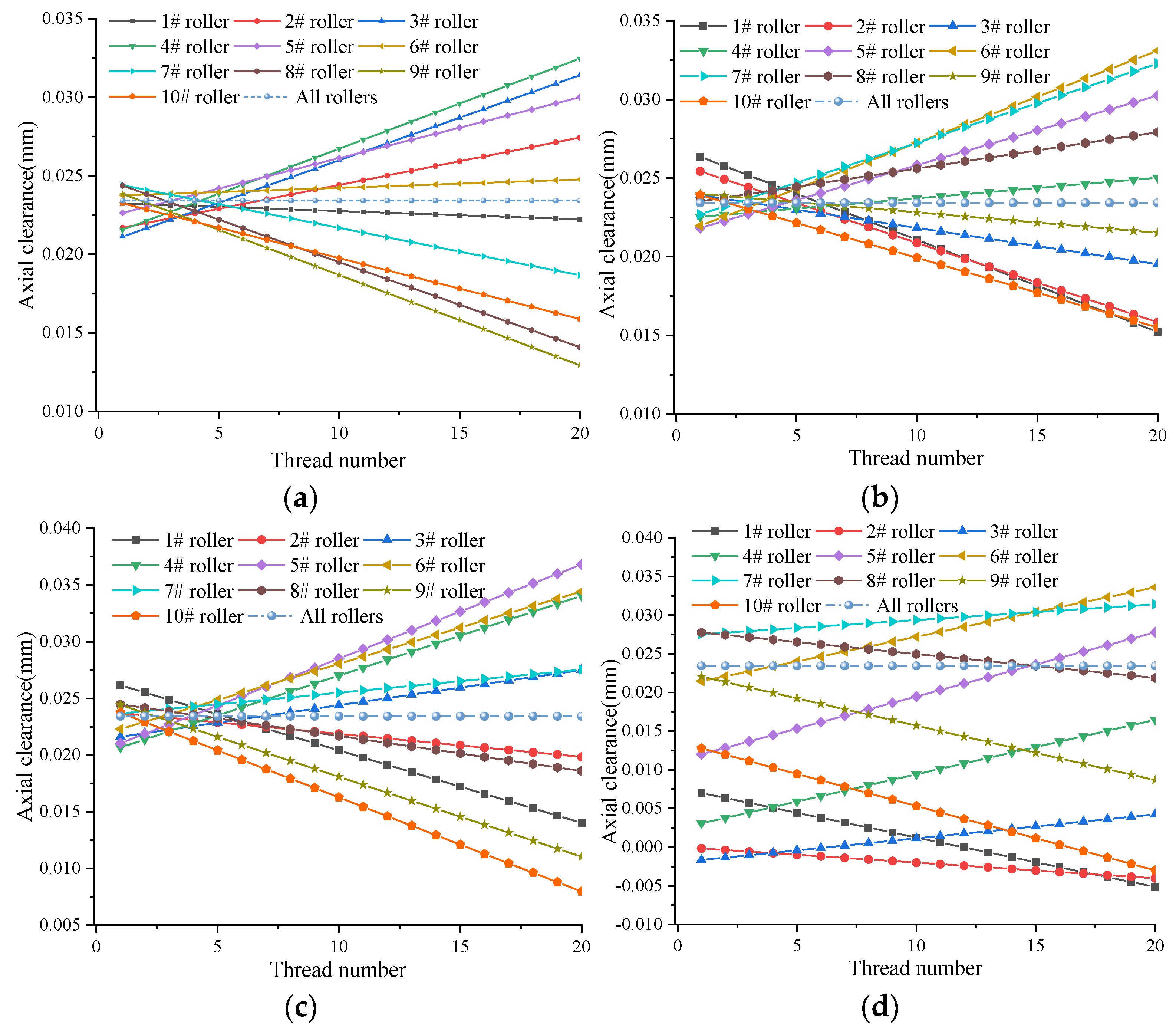
- The instant contact points and contact clearances are predicted by the unloaded meshing simulation. The simulation result suggests the misaligned angle errors slightly affect the contact positions and axial clearances of the PRSM, while the offset errors obviously change the contact positions and increase axial clearances. However, the difference between the maximum and minimum clearances caused by the offset error is equal and that of the axial clearance between adjacent threads is also the same.
- (2)
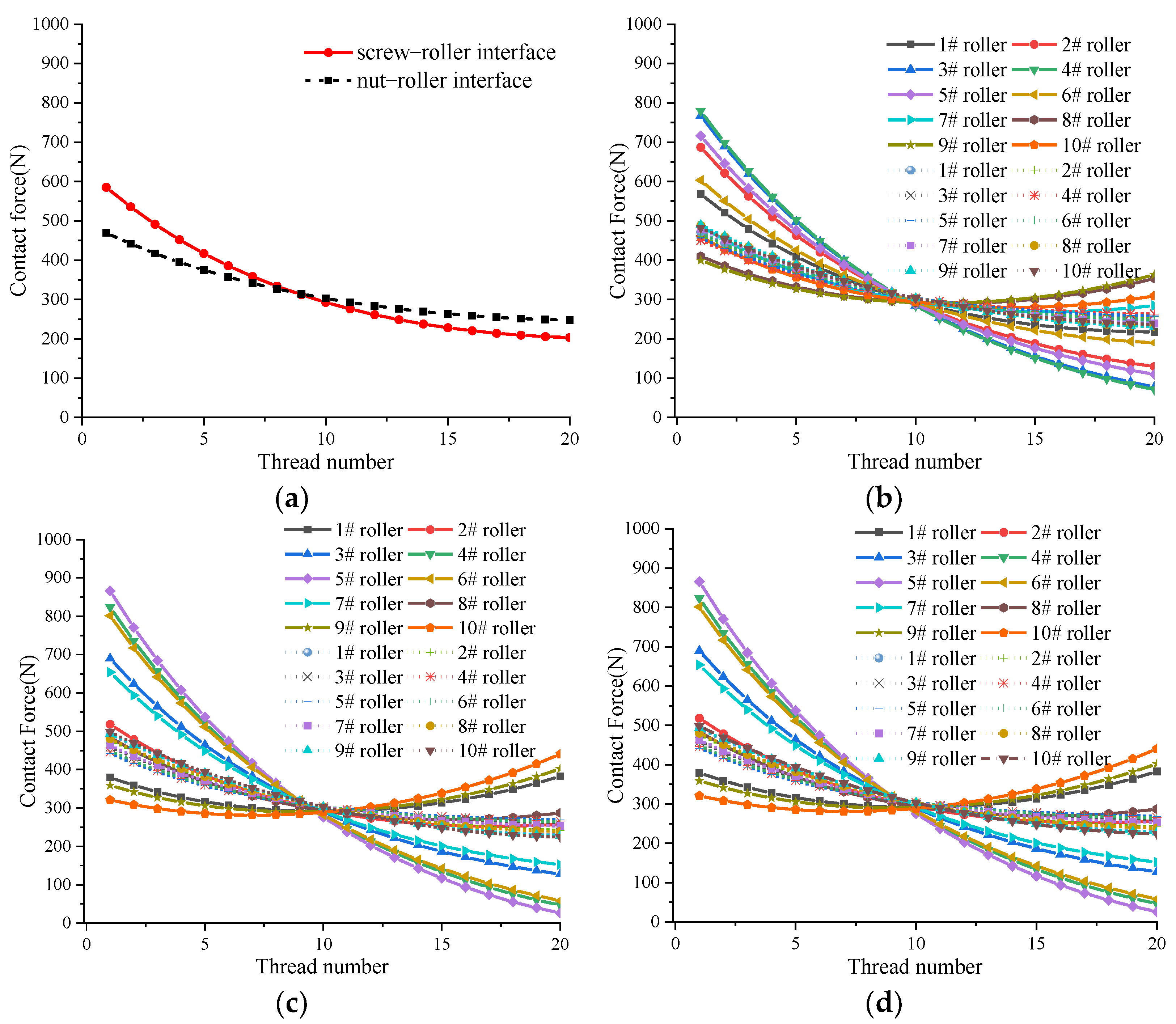
- The load distribution is calculated based on the improved load model considering the variation of axial clearances and contact angles. Based on the numerical results, the load distribution is greatly affected by the misalignment angles of the screw. Those results are validated by taking advantage of the results obtained from the FEA. Moreover, the contact forces of the misaligned PRSM change periodically under normal working conditions, while those of the aligned PRSM are constant under the same thread teeth.
- (3)
- The precision loss is predicted by the accumulated wear depth. The variables (such as contact forces, contact ellipses and sliding velocities) which have affected the results of the wear depth are taken into consideration.
These results disclose several significant performance characteristics of the PRSM considering screw misalignments in engineering applications. Meanwhile, the aforementioned analysis and discussion can provide a useful guide for the selection, assembling and use of the PRSM.
Author Contributions
Conceptualization, J.M. and X.D.; methodology, J.M.; software, J.M.; validation, J.M., X.D. and J.Z.; formal analysis, J.M.; investigation, J.M.; resources, L.W.; data curation, J.Z.; writing—original draft preparation, J.M.; writing—review and editing, X.D.; visualization, D.W.; supervision, D.W.; project administration, X.Z. All authors have read and agreed to the published version of the manuscript.
Funding
This research received no external funding.
Institutional Review Board Statement
Not applicable.
Informed Consent Statement
Not applicable.
Data Availability Statement
Not applicable.
Conflicts of Interest
The authors declare no conflict of interest.
Nomenclature
| a: b | Semi-major and the semi-minor axes of contact ellipse, respectively, (mm) |
| cs, cr, cn | Half of thread tooth thickness of the screw, roller and nut, respectively, (mm) |
| d0s, d0r, d0n | Nominal diameters of the screw, roller and nut, respectively, (mm) |
| d1s, d1r, d1n | Root diameters of the screw, roller and nut, respectively, (mm) |
| d2s, d2r, d2n | Outside diameters of the screw, roller and nut, respectively, (mm) |
| Axial clearances at screw-roller and roller-nut interfaces, respectively, (mm) | |
| Wear depth at screw-roller and roller-nut interfaces, respectively, (mm) | |
| ma, mb | Major and minor semi-axis coefficients of the contact ellipse, respectively, (mm) |
| rs, rr, rn | Nominal radius of the screw, roller and nut, respectively, (mm) |
| us, ur, un | Surface coordinates of the screw, roller and nut, respectively, (mm) |
| ws, wp | Rotate speed of the screw and revolution speed of the roller, respectively, (mm) |
| As, Ar, An | Cross-sectional area of the screw, roller and nut, respectively, (mm) |
| Nominal contact area of the contact ellipse at screw-roller and roller-nut interfaces, respectively, (mm2) | |
| Es, Er, En | Effective Young’s modulus of the screw, roller and nut, respectively, (MPa) |
| Axial forces at screw-roller and roller-nut interfaces, respectively, (mm) | |
| Fn | Normal contact force, (N) |
| Axial stiffness of the screw, roller and nut, respectively, (mm) | |
| Hertz contact stiffnesses at screw-roller and roller-nut interfaces, respectively, (mm) | |
| Ls, Ls0 | Effective travel of the screw and length of the abraded areas of the screw, respectively (mm) |
| R | Radius of the effective ball of the roller, (mm) |
| Greek letters | |
| θsx, θsy | Misalignment angle errors in xs and ys direction, respectively, (rad) |
| θs, θm, θn | Rotate angles about screw, roller and nut, respectively, (rad) |
| εs | Offset vector in the screw |
| ζs, ζsr, ζn | Axial deformation, (mm) |
| τi | Separation angle of i# roller with respect to 1# roller, (rad) |
References
- Lohmeier, S.; Buschmann, T.; Ulbrich, H. Humanoid robot LOLA. In Proceedings of the 2009 IEEE International Conference on Robotics and Automation, Kobe, Japan, 12–17 May 2009; pp. 775–780. [Google Scholar]
- Garcia, J.R.; Cusido, J.; Rosero, J.A.; Ortega, J.A.; Romeral, L. Reliable electro-mechanical actuators in aircraft. IEEE Aerosp. Electron. Syst. Mag. 2008, 23, 19–25. [Google Scholar] [CrossRef]
- Li, L.; Fu, Y.; Zheng, S.; Fu, J.; Xia, T. Friction Torque Analysis of Planetary Roller Screw Mechanism in Roller Jamming. Math. Probl. Eng. 2020, 2020, 1392380. [Google Scholar] [CrossRef]
- Ma, S.; Wu, L.; Fu, X.; Li, Y.; Liu, G. Modelling of static contact with friction of threaded surfaces in a planetary roller screw mechanism. Mech. Mach. Theory 2019, 139, 212–236. [Google Scholar] [CrossRef]
- Ma, S.; Liu, G.; Tong, R.; Fu, X. A Frictional Heat Model of Planetary Roller Screw Mechanism Considering Load Distribution. Mech. Based Des. Struct. Mach. 2015, 43, 164–182. [Google Scholar] [CrossRef]
- Xie, Z.; Xue, Q.; Wu, J.; Gu, L.; Wang, L.; Song, B. Mixed-lubrication analysis of planetary roller screw. Tribol. Int. 2019, 140, 105883. [Google Scholar] [CrossRef]
- Wu, L.; Ma, S.; Wan, Q.; Liu, G. Dynamic Model of Planetary Roller Screw Mechanism with Considering Torsional Degree of Freedom. In Proceedings of the 6th International Conference on Mechatronics and Mechanical Engineering (ICMME 2019), Osaka, Japan, 27–30 November 2020; p. 1003. [Google Scholar] [CrossRef] [Green Version]
- Fu, X.; Liu, G.; Ma, S.; Tong, R.; Li, X. An efficient method for the dynamic analysis of planetary roller screw mechanism. Mech. Mach. Theory 2020, 150, 103851. [Google Scholar] [CrossRef]
- Fu, X.; Liu, G.; Tong, R.; Ma, S.; Lim, T.C. A nonlinear six degrees of freedom dynamic model of planetary roller screw mechanism. Mech. Mach. Theory 2018, 119, 22–36. [Google Scholar] [CrossRef]
- Jones, M.H.; Velinsky, S.A.; Lasky, T.A. Dynamics of the Planetary Roller Screw Mechanism. J. Mech. Robot. 2015, 8, 014503. [Google Scholar] [CrossRef]
- Meng, J.; Du, X.; Li, Y.; Chen, P.; Xia, F.; Wan, L. A Multiscale Accuracy Degradation Prediction Method of Planetary Roller Screw Mechanism Based on Fractal Theory Considering Thread Surface Roughness. Fractal Fract. 2021, 5, 237. [Google Scholar] [CrossRef]
- Velinsky, S.A.; Chu, B.; Lasky, T.A. Kinematics and Efficiency Analysis of the Planetary Roller Screw Mechanism. J. Mech. Des. 2008, 131, 011016. [Google Scholar] [CrossRef]
- Jones, M.H.; Velinsky, S.A. Contact Kinematics in the Roller Screw Mechanism. J. Mech. Des. 2013, 135, 051003. [Google Scholar] [CrossRef]
- Liu, Y.; Shang, Y.; Wang, J. Mathematical analysis of the meshing performance of planetary roller screws applying different roller thread shapes. Adv. Mech. Eng. 2017, 9, 1687814017703009. [Google Scholar] [CrossRef]
- Liu, Y.; Wang, J.; Cheng, H.; Sun, Y. Kinematics Analysis of the Roller Screw Based on the Accuracy of Meshing Point Calculation. Math. Probl. Eng. 2015, 2015, 303972. [Google Scholar] [CrossRef] [Green Version]
- Fu, X.; Liu, G.; Ma, S.; Tong, R.; Lim, T.C. A Comprehensive Contact Analysis of Planetary Roller Screw Mechanism. J. Mech. Des. 2017, 139, 012302. [Google Scholar] [CrossRef]
- Xiaojun, F.U.; Geng, L.I.U.; Shangjun, M.A. Meshing Properties of Planetary Roller Screw Mechanism within Misalignments. Chin. J. Mech. Eng. 2017, 53, 25–33. [Google Scholar] [CrossRef]
- Du, X.; Chen, B.; Liu, R.; Li, C. Research on Fractal Model of Load Distribution and Axial Stiffness of Planetary Roller Screw Mechanism Considering Surface Roughness and Friction Factor. Adv. Theory Simul. 2022, 5, 2100399. [Google Scholar] [CrossRef]
- Du, X.; Chen, B.; Zheng, Z. Investigation on mechanical behavior of planetary roller screw mechanism with the effects of external loads and machining errors. Tribol. Int. 2021, 154, 106689. [Google Scholar] [CrossRef]
- Zhang, W.; Liu, G.; Ma, S.; Tong, R. Load distribution over threads of planetary roller screw mechanism with pitch deviation. Proc. Inst. Mech. Eng. Part C J. Mech. Eng. Sci. 2019, 233, 4653–4666. [Google Scholar] [CrossRef]
- Zhang, W.; Liu, G.; Tong, R.; Ma, S. Load distribution of planetary roller screw mechanism and its improvement approach. Proc. Inst. Mech. Eng. Part C J. Mech. Eng. Sci. 2016, 230, 3304–3318. [Google Scholar] [CrossRef]
- Sandu, S.; Biboulet, N.; Nelias, D.; Abevi, F. Analytical prediction of the geometry of contact ellipses and kinematics in a roller screw versus experimental results. Mech. Mach. Theory 2019, 131, 115–136. [Google Scholar] [CrossRef]
- Aurégan, G.; Fridrici, V.; Kapsa, P.; Rodrigues, F. Wear Behavior of Martensitic Stainless Steel in Rolling-Sliding Contact for Planetary Roller Screw Mechanism: Study of the WC/C Solution. Tribol. Online 2016, 11, 209–217. [Google Scholar] [CrossRef] [Green Version]
- Aurégan, G.; Fridrici, V.; Kapsa, P.; Rodrigues, F. Experimental simulation of rolling–sliding contact for application to planetary roller screw mechanism. Wear 2015, 332–333, 1176–1184. [Google Scholar] [CrossRef]
- Wei, C.-C.; Liou, W.-L.; Lai, R.-S. Wear analysis of the offset type preloaded ball–screw operating at high speed. Wear 2012, 292–293, 111–123. [Google Scholar] [CrossRef]
- Zhou, H.-X.; Zhou, C.-G.; Feng, H.-T.; Ou, Y. Theoretical and experimental analysis of the preload degradation of double-nut ball screws. Precis. Eng. 2020, 65, 72–90. [Google Scholar] [CrossRef]
- Zhou, C.-G.; Zhou, H.-X.; Feng, H.-T. Experimental analysis of the wear coefficient of double-nut ball screws. Wear 2020, 446–447, 203201. [Google Scholar] [CrossRef]
- Zhou, C.-G.; Ou, Y.; Feng, H.-T.; Chen, Z. Investigation of the precision loss for ball screw raceway based on the modified Archard theory. Ind. Lubr. Tribol. 2017, 69, 166–173. [Google Scholar] [CrossRef]
- Liu, J.; Ma, C.; Wang, S. Precision loss modeling method of ball screw pair. Mech. Syst. Signal Process. 2020, 135, 106397. [Google Scholar] [CrossRef]
- Cheng, Q.; Qi, B.; Liu, Z.; Zhang, C.; Xue, D. An accuracy degradation analysis of ball screw mechanism considering time-varying motion and loading working conditions. Mech. Mach. Theory 2019, 134, 1–23. [Google Scholar] [CrossRef]
- Liu, G.; Ma, S.; Fu, X. Planetary Roller Screw Drive: Meshing Principle; Science Press: Beijing, China, 2019. [Google Scholar]
- Jones, M.H.; Velinsky, S.A. Stiffness of the Roller Screw Mechanism by the Direct Method. Mech. Based Des. Struct. Mach. 2014, 42, 17–34. [Google Scholar] [CrossRef]
Publisher’s Note: MDPI stays neutral with regard to jurisdictional claims in published maps and institutional affiliations. |
© 2022 by the authors. Licensee MDPI, Basel, Switzerland. This article is an open access article distributed under the terms and conditions of the Creative Commons Attribution (CC BY) license (https://creativecommons.org/licenses/by/4.0/).