Article

Research on the Mechanism of the Stiffness Performance of Rolling Bearings under Wrong Assembly State

1
School of Mechanical and Precision Instrument Engineering, Xi’an University of Technology, Xi’an 710048, China
2
Luoyang Bearing Science & Technology Co., Ltd., Luoyang 471039, China
*
Authors to whom correspondence should be addressed.
Lubricants 2022, 10(6), 116; https://doi.org/10.3390/lubricants10060116
Submission received: 11 April 2022 / Revised: 30 May 2022 / Accepted: 31 May 2022 / Published: 5 June 2022
(This article belongs to the Special Issue Advances in Bearing Lubrication and Thermal Sciences)

Abstract

:
In this paper, a quasi-static angular contact ball bearing model, considering assembly accuracy is constructed, while a numerical solution method for bearing stiffness under bad assembly state is established. A 7014C angular contact ball bearing is used as the research object and five groups of different spacer inclinations are designed to imitate the installation error of the spindle bearing. The bearing stiffness performance was comparatively analyzed, according to the five spacers. The effect of preload and rotation speed on bearing stiffness are systematically investigated, considering different parallelism errors, as induced by the spacers. The influence mechanism of the badly assembled bearing on the respective stiffness anisotropy is studied based on the proposed model. The results show that the variations of the inclination between the inner and outer rings of the bearing exhibit a very weak effect on the axial stiffness, while the influence on the radial and angular stiffness is more significant.

1. Introduction

The factors that affect the performance of a machine tool, over the course of a spindle system’s whole life cycle, include not only the quality of the spindle components, but also the design of the spindle system, the component assembly process and the assembly technique. Angular contact ball bearings have a significant impact on the performance of the spindle system, as the core rotating support element, while bearing stiffness performance indicators have a direct impact on spindle system vibration, noise, rotational precision, end jump and service life [1,2,3,4,5]. Moreover, the accuracy of the bearing stiffness values is crucial in building a global model of the spindle system. Indeed, the frequency response function and, in particular, the critical eigenfrequencies are directly linked to the bearings’ stiffness. As a result, additional quantitative study is required, to investigate the relationship between bearing assembly quality and bearing stiffness in all directions, in order to determine how the bearing assembly quality affects the stiffness performance of the bearing and even the spindle system.
Ball bearings, as a kind of rolling bearing, are one of the most important parts of spindle-bearing system. Many researchers [6,7,8] established that spindle performance changes dynamically due to the nonlinear effect of bearings stiffness. A great number of scholars have conducted studies on bearing stiffness, including bearing stiffness analysis and calculation, as well as bearing stiffness change affect factor analysis [9]. Jones, for example, was the first to develop the rolling bearing contact angle analysis mechanics model, which was the basis for the numerical assessment of the bearing load and change law, while Harris later enhanced the model and it was widely accepted by other researchers as Jones and Harris model [10,11].
J. Jedrzejewski [12] researched the relationship between the rotation speed and bearing stiffness, deriving the “bearing stiffness softening phenomenon”, where the bearing stiffness continues to drop, as the bearing rotational speed rises. Matti Rantatalo [13] held the same view and the respective research also pointed that the radial stiffness would drop to 40%, when the rotational speed was up to 20,000 rpm, based on the presented calculations. However, both of them did not give a detailed calculation model to explain the speed varying stiffness, dependent on the analysis of bearing contact force. In the work of Sheng et al. [14]., the detail notion of rolling bearing speed-varying stiffness is introduced and explained, based on the relations of load-deflection, according to the bearing dynamic model, also based on Jones and Harris’s model.
David Noel [15] proposed a new method for the computation of the stiffness matrix: a complete analytical expression is presented, including dynamic effects, in order to ensure accuracy at high shaft speed. This new method is particularly relevant in the case of lightly loaded bearings in critical applications (both high values of shaft speed and ball orbital diameter). Yi Guo [16] developed a finite element/contact mechanics model for rolling element bearings, with the focus on obtaining accurate bearing stiffness for a wide range of bearing types and parameters. The presented fully-populated stiffness matrix demonstrates the coupling between bearing radial, axial and tilting bearing deflections. However, this method did not consider the rotational speed effect on the bearing stiffness.
Cao [17] et al. tested the influence of bearing positioning preload and constant pressure preload on spindle-bearing dynamic stiffness, concluding that positioning preload is more effective than constant pressure preload in preserving spindle dynamic stiffness, under cutting loads at high speeds. Aramaki [18] studied bearing stiffness under the influence of preload force and confirmed the mapping link between preload force and bearing stiffness features. Yang [19] used the proposed static model of rolling bearing, to calculate the dynamic stiffness of the bearing and determined its operational stiffness, considering the influence of rotational speed, initial preload force, thermal preload force and oil film thickness on bearing stiffness. Liu [20] suggested a methodology, based on finite element analysis, in order to study the influence of preload on bearing stiffness and discover the bearing’s equilibrium state while under load.
The experiment about bearing stiffness has also been conducted by many researchers. Walford et al. [21] developed a spindle-bearing test platform, to estimate the bearing’s radial stiffness and damping, by measuring the response of the spindle, as well as to determine the effect of temperature on the stiffness of the bearings. Similarly, Kraus et al. [22] pointed out that, static bearing stiffness is very close to the stiffness measured while the bearing is running, based on stiffness and damping characteristics of a radial ball bearing, as derived by experimental modal tests. Marsh E R et al. [23] carried out an experimental measurement of precision bearing dynamic stiffness, where it was pointed out that an analysis of the method is sensitive to errors in sensor location, while several practical advantages of the proposed approach, over traditional static testing, were demonstrated. However, the majority of the above studies are based on a mechanical model of the bearing, under ideal operating conditions. Nonetheless, in engineering applications, various errors and even installation eccentricity in the bearing-spindle coupling system are inherent, while the bearing operation is affected by the additional moment.
Recently, ring misalignment occurrence has attracted much attention from the academia. Many researchers are devoted to studying the effect of ring misalignment error on the operating characteristics of rolling bearings. Zhang [24] studied the effect of ring misalignment on the service characteristics of ball bearing and rotor system; however, the analysis of bearing stiffness is not the key research content of this study. Xu [25] researched the effect of angular misalignment of inner ring on the surface contact characteristics and stiffness coefficients of duplex angular contact ball bearing. It was pointed out that, the ring misalignment considerably changes the surface contact characteristics of ball-raceway and causes uneven load distribution. As a result, Zhang [26] built a model that included the bearing’s deflection angle and assessed the effect of axial and radial loads on the contact angle, but the change law of bearing stiffness performance was not investigated.
This issue is addressed in this paper, where the mechanism of bearing stiffness change is studied, in the context of poor assembly. Furthermore, the influence of rotational speed, preload and assembly quality on bearing stiffness, in all directions, is systematically analyzed (the relative tilt amount of the inner and outer ring of the bearing), while the quantitative description of the bearing, from the assembly error expression to bearing stiffness performance change, is realized.

2. Bearing Stiffness Solution Model Construction

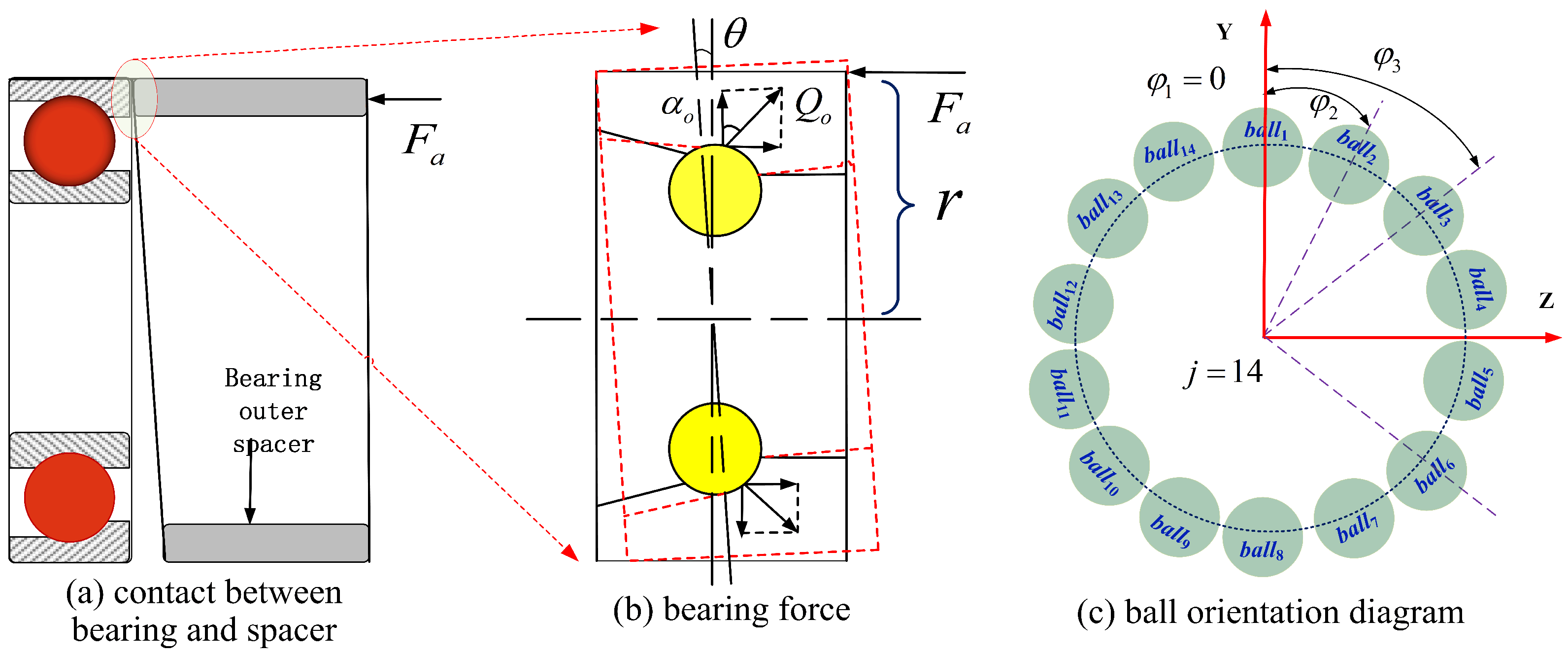
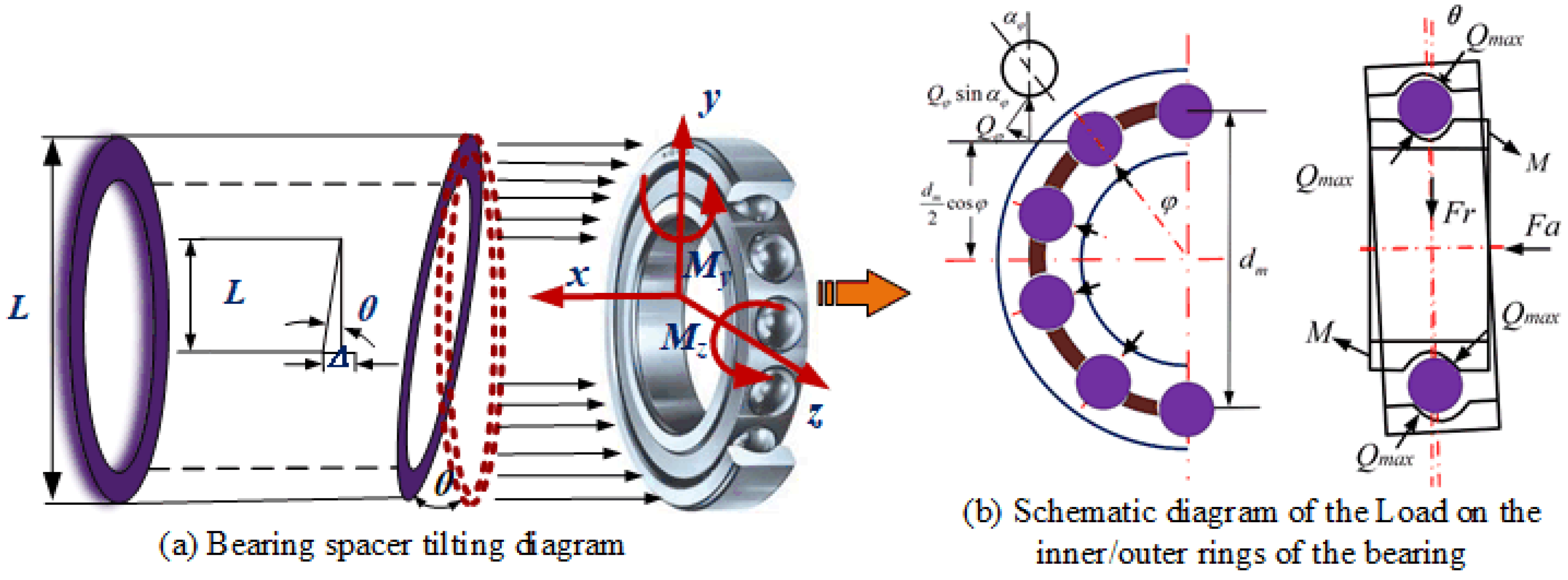
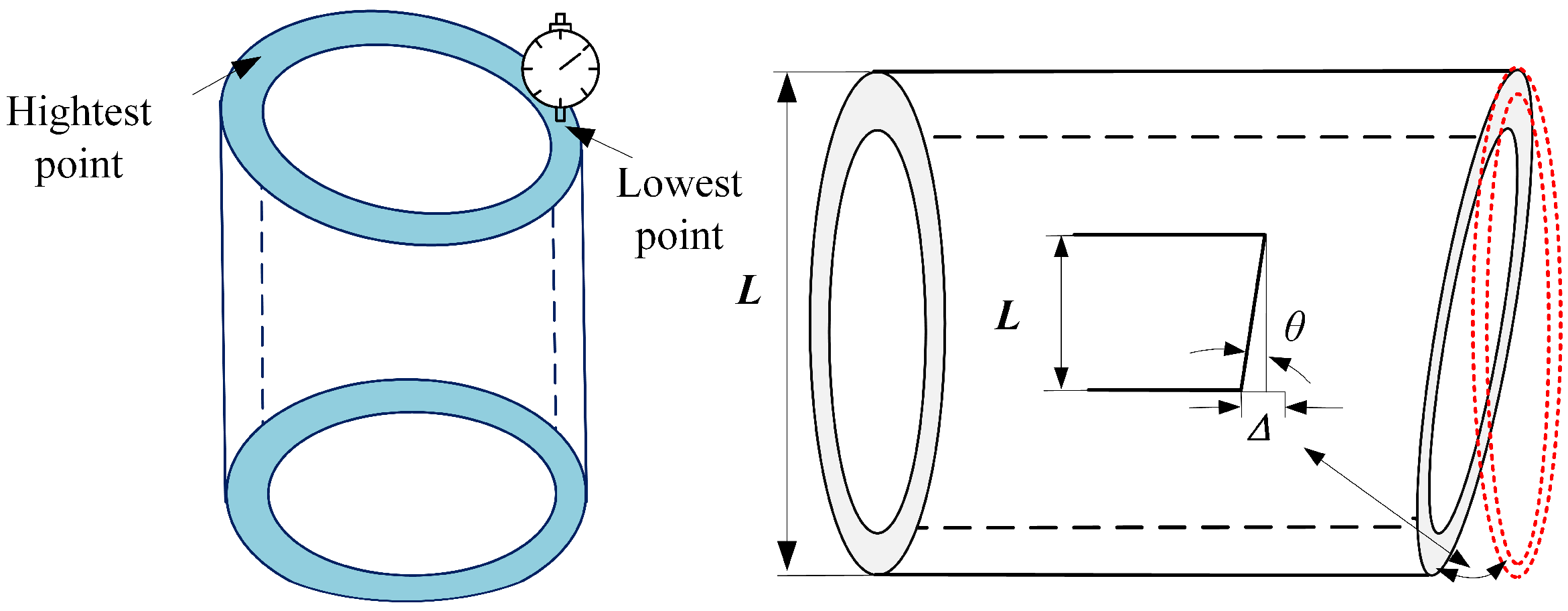
2.1. Equivalent Transformation of Bearing Spacer Non-Parallel

A common way to adjust the initial assembly preload of spindle bearings is the use of spacers. In the case where the spacer end faces are not parallel, there is a greater impact on the bearing’s initial assembly state, causing the bearing to operate in a relatively tilted attitude, between the inner and outer rings, which affects the bearing’s mechanical and stiffness characteristics. This approach allows for the simulation of various bearing spacer tilting circumstances. Figure 1 shows the tilting of the spacer and the subsequent changes in the forces on the bearing’s inner and outer rings.
The bearing outer ring force equilibrium equation is determined using the force analysis diagram in Figure 1:
F a F r = j Z Q o j sin α o j λ o j M g j D b cos α o j j Z Q o j sin α o j λ o j M g j D b cos α o j
where, Fa represents the axial load applied on the bearing (N); Fr is the radial load applied on bearing (N); Z is the number of the rolling balls; Qoj is the contact load between jth ball and outer ring (); α o j is the contact angle between the jth ball and the outer ring (rad); Mgj is the gyroscopic moment of the jth rolling element (N·mm); Db is the diameter of the rolling ball; λ o j is the load distribution coefficient of outer raceway.
Furthermore, in the case of bearing spacer non-parallelism, caused by the relative tilt of the bearing’s inner and outer rings, the contact force created on the rolling body and raceway contact region produces a moment M, relative to the inner and outer ring of the bearing tilt, whose value is calculated as follows:
M = j Z Q o j sin α o j λ o j M g j D b cos α o j R o + λ o j M g j D b r o cos φ j
where, Ro is the radius of the outer raceway curvature center (mm); r is the distance from the point of load force application to the axis (mm); φ j is the orientation of the jth rolling element (rad).
It is evident that, due to the non-parallelism of the spindle spacer and the resulting bearing inner ring, the outer ring experiences a relative tilt, causing non-uniformity in the rolling body and raceway contact area, while under load, which triggers the additional bending moment and has an impact on the bearing stiffness performance.

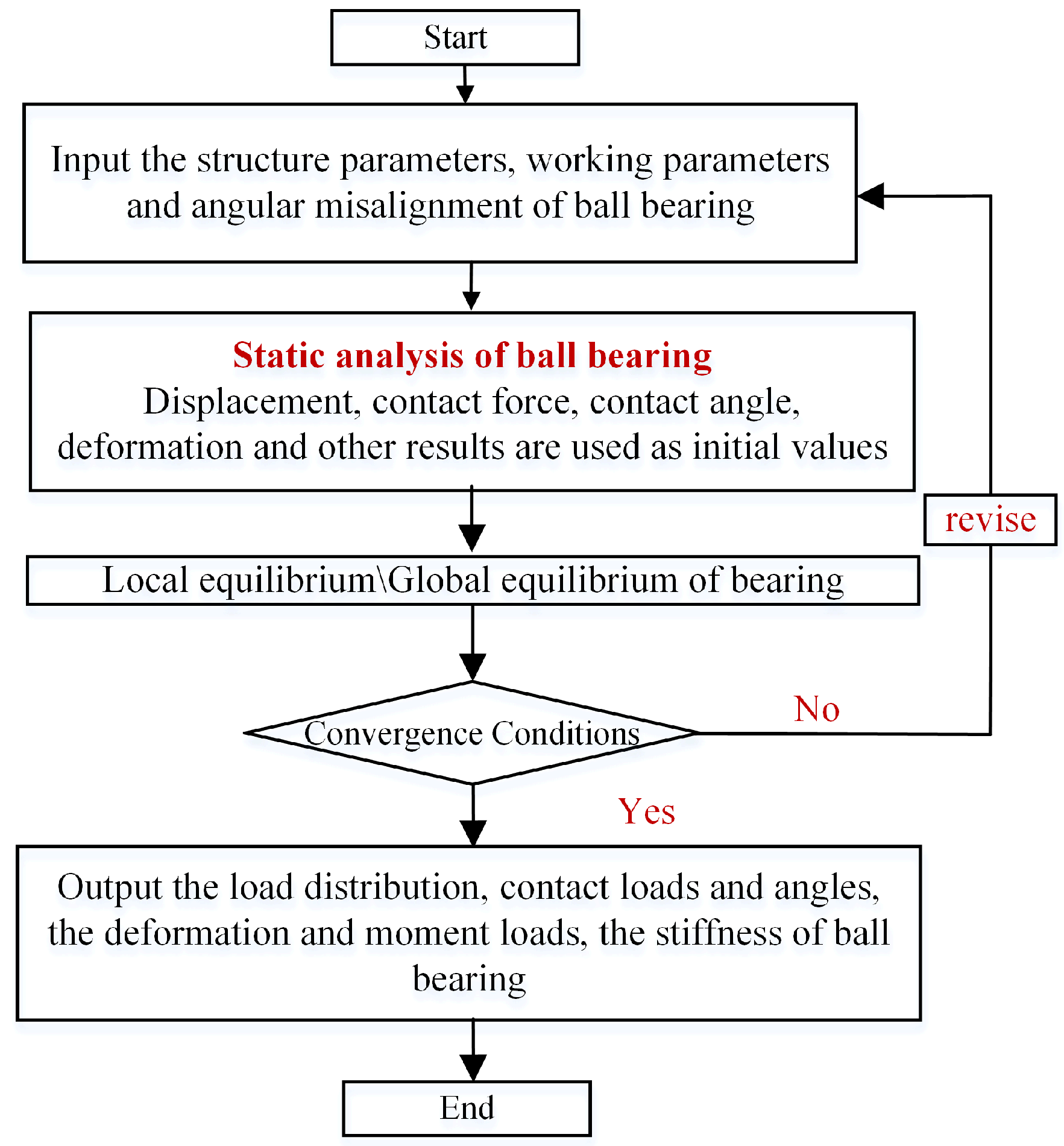
2.2. Bearing Stiffness Solution

The 5th order square matrix, created by taking the partial derivative of the external load f applied to the bearing, against the relative displacement d of the inner and outer rings of the bearing, is the analytical way of solving the bearing stiffness matrix. The Jones model is used to calculate the three-degree-of-freedom hydrostatic parameters, used as the initial value of the iterative algorithm to obtain the proposed three-degree-of-freedom hydrostatic solution parameters. Next, the derived three-degree-of-freedom hydrostatic parameters are used as the initial value of the Newton-Raphson iterative solution method, used to obtain the proposed five-degree-of-freedom hydrostatic parameters of the bearing and solve the 4Z + 5 equations. In the solution process, each rolling element equation is a local equation, whereas the overall bearing force equation is a global equation. The solution variables for each rolling element are: X = {X1, X2, δi, δo}j, j = 1, 2…Z where Z is the number of scrolling bodies and is called the local solution variable. f = {Fx, Fy, Fz, My, Mz} is called a global load variable, d = {δx, δy, δz, θy, θz} is called a universal displacement variable. According to the global equations, the overall bearing force and each rolling body force are related, so when solving the overall bearing force equation, each rolling body equilibrium equation must also be solved, joining each rolling body solution formula and force equilibrium equation. The specific solution flow is shown in Figure 2.

3. Bearing Stiffness Solution Condition Settings

In this paper, the well-known commercially available precision angular contact ball bearing 7014C is employed, with parameters as listed in Table 1.
The end face of the spacer is always machined with one end face as the reference surface and the other end face is ground. Due to manufacturing errors, the machined surface is not perfectly flat. In other words, there is a parallelism error between the machined end face of the spacer and the reference surface, which is depicted in Figure 2. To facilitate analysis and calculation, this paper uses the inclination angle θ of the spacer end face to characterize the non-parallelism of the spacer end face, expressed as:
θ = arctan Δ L
where L is the outer diameter dimension of the outer spacer (mm), in relation to the mating bearing. This paper is based on the analysis of the 7210C bearing, so the value of L is 90 mm; Δ : The height difference between the highest point and the lowest point of the spacer end face (μm) is shown in Figure 3.
For theoretical analysis purposes, several groups of spacers with parallelism errors are set up in this study, which are denoted as: Δ = 10 μm, 20 μm, 30 μm, 40 μm, while the corresponding tilt angle values of these four groups of outer spacers with parallelism errors are: θ 1 = 0.0052 , θ 2 = 0.0104 , θ 3 = 0.0156 , θ 4 = 0.0208 as listed in Table 2. According to the NSK bearing manual, the spacer face runout within 3 μm is within the design error tolerance, so the spacer mark within the design error range is: Δ = 0 μm, which indicates a well parallel spacer. The angle of tilt is noted as: θ 0 = 0 . In contrast with the tilting of a bearing, caused by an individually applied bending moment, when the bearing is tilted due to a dimensional error in the outer spacer, the bearing is also tilted to a certain extent by the geometric constraints of the spacer end face.
The analysis shows that, in the assembly of the spindle, there will be a tilting gap between the outer spacer and the bearing outer ring, due to the existence of the tilting angle of the outer spacer end face. As shown in Figure 4, the bearing and housing is usually a clearance fit, resulting in clearance inside the bearing. There is a possibility of the bearing outer ring being tilted, during the transfer of force, under the action of the axial assembly force and the contact between the tilted end face of the outer spacer and the bearing outer ring.
The notion of bearing mounting quality, as opposed to the ideal load bearing stiffness change law, can more accurately reflect the actual engineering application of bearing stiffness performance, bearing mounting quality analysis, bearing joint parts quality on the bearing and even spindle stiffness service performance of the mechanism. In this view, it is the bearing mounting quality and recommended assembly parameters in real-world engineering applications that are considered in this paper; as well as a number of working scenarios for the investigation of bearing stiffness performance, with exact factors (Table 2). Different speed values (at 1000 rpm increments), preload conditions and bearing deflection circumstances are all used to compute stiffness variations.

4. Analysis of Factors Influencing Bearing Stiffness

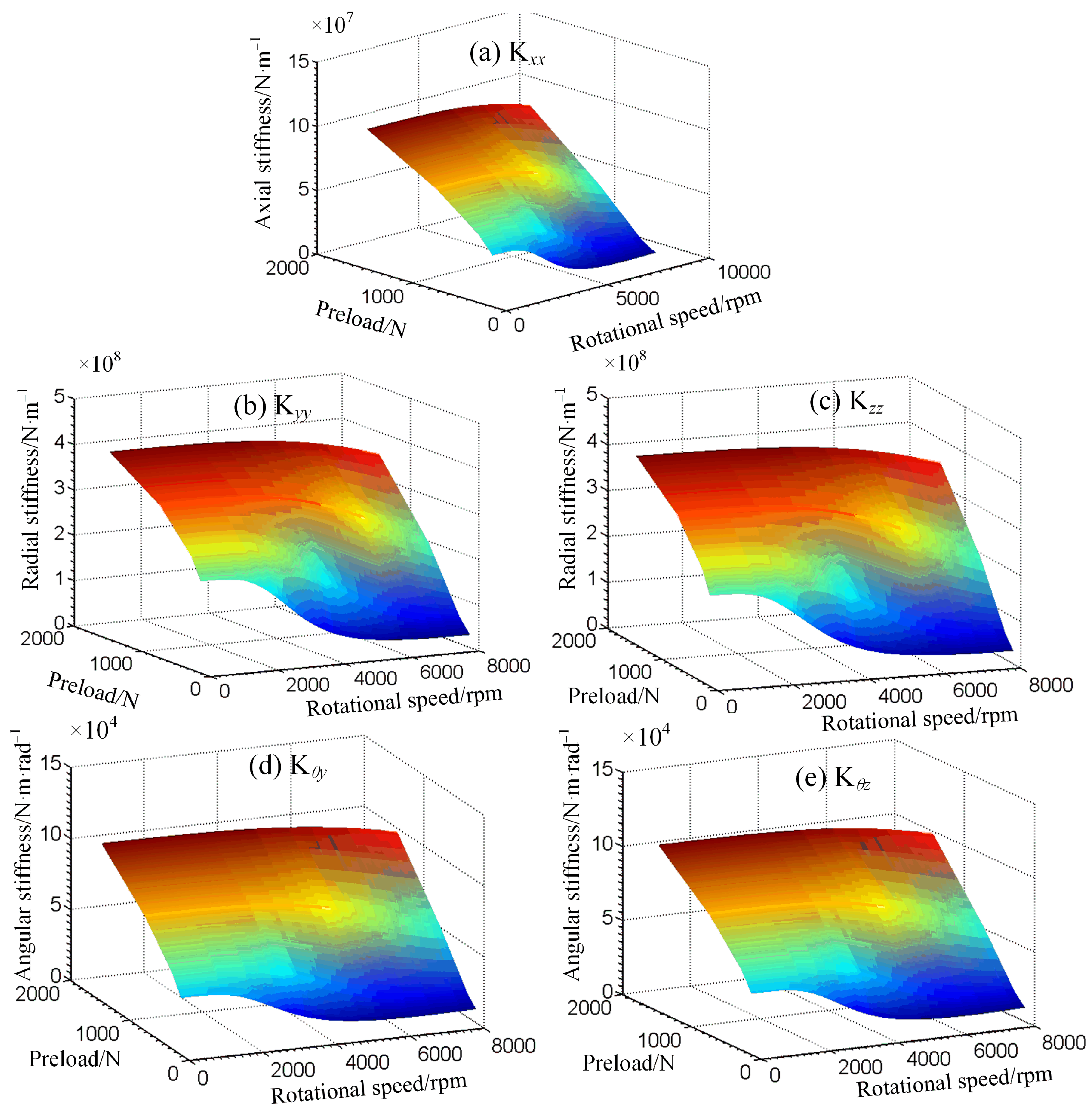
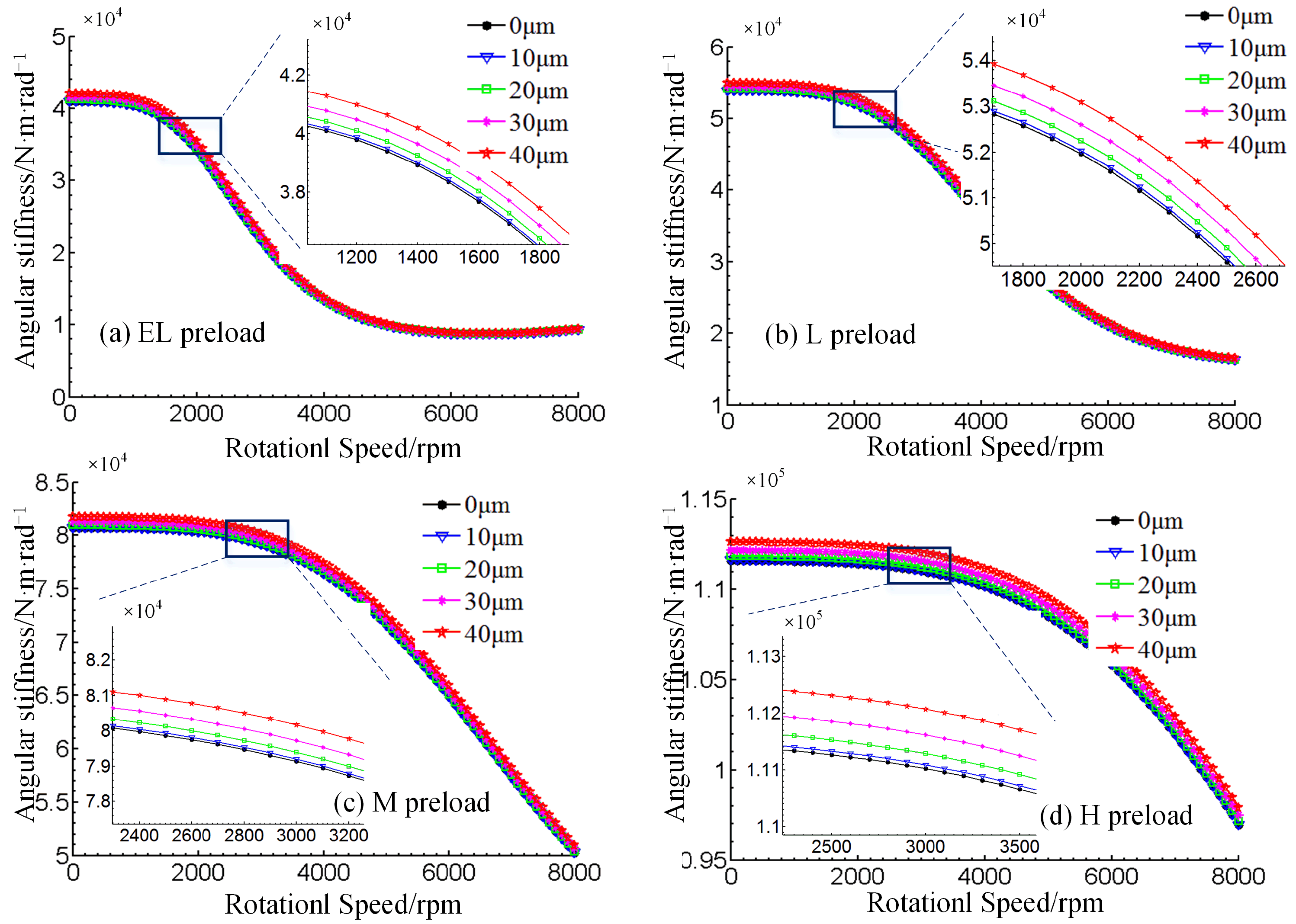
4.1. Bearing Stiffness Variation Law under Different Working Conditions

The variation of axial, radial and angular stiffness values on a macro scale reflects the bearing stiffness characteristics. The diagram in Figure 5 demonstrates that there are five surfaces (five surfaces indicate five different tilt conditions: 0 μm −10 μm −20 μm −30 μm −40 μm). It is harder to determine that this is a superposition of five surfaces, based on the three-dimensional surface diagram. More specifically, the effect of tilting the inner and outer rings of the bearing on its overall axial stiffness Kxx, radial stiffness Kyy, radial stiffness Kzz, angular stiffness Kθy and angular stiffness Kθz does not cause significant value fluctuation. The reason for this could be that some of the local differences in surface changes are difficult to discern in 3D views, while the changes in bearing stiffness are so miniature that they are difficult to reflect on the overall stiffness change relationship graph.
As a result, a view is transformed to analyze the stiffness variation rule (Figure 6). It is observed that the bearing stiffness varies significantly under different preloads. Specifically, raising the bearing preload can effectively improve bearing stiffness performance, whereas as preload and speed increase, bearing stiffness reduces significantly (bearing heavy preload versus light preload conditions). In addition, the axial stiffness is one order of magnitude lower, compared to the radial stiffness, while no significant variation is found between the horizontal radial stiffness and the vertical radial stiffness, as well as between the two angular stiffness components Kθy. The bearing stiffness variations in all directions, in relation to its inner and outer ring tilt angle fluctuations, are not obvious but exhibit a certain regularity. That is, stiffness increases and decreases in relation to spindle speed and preload force, while it is not a linear relationship.

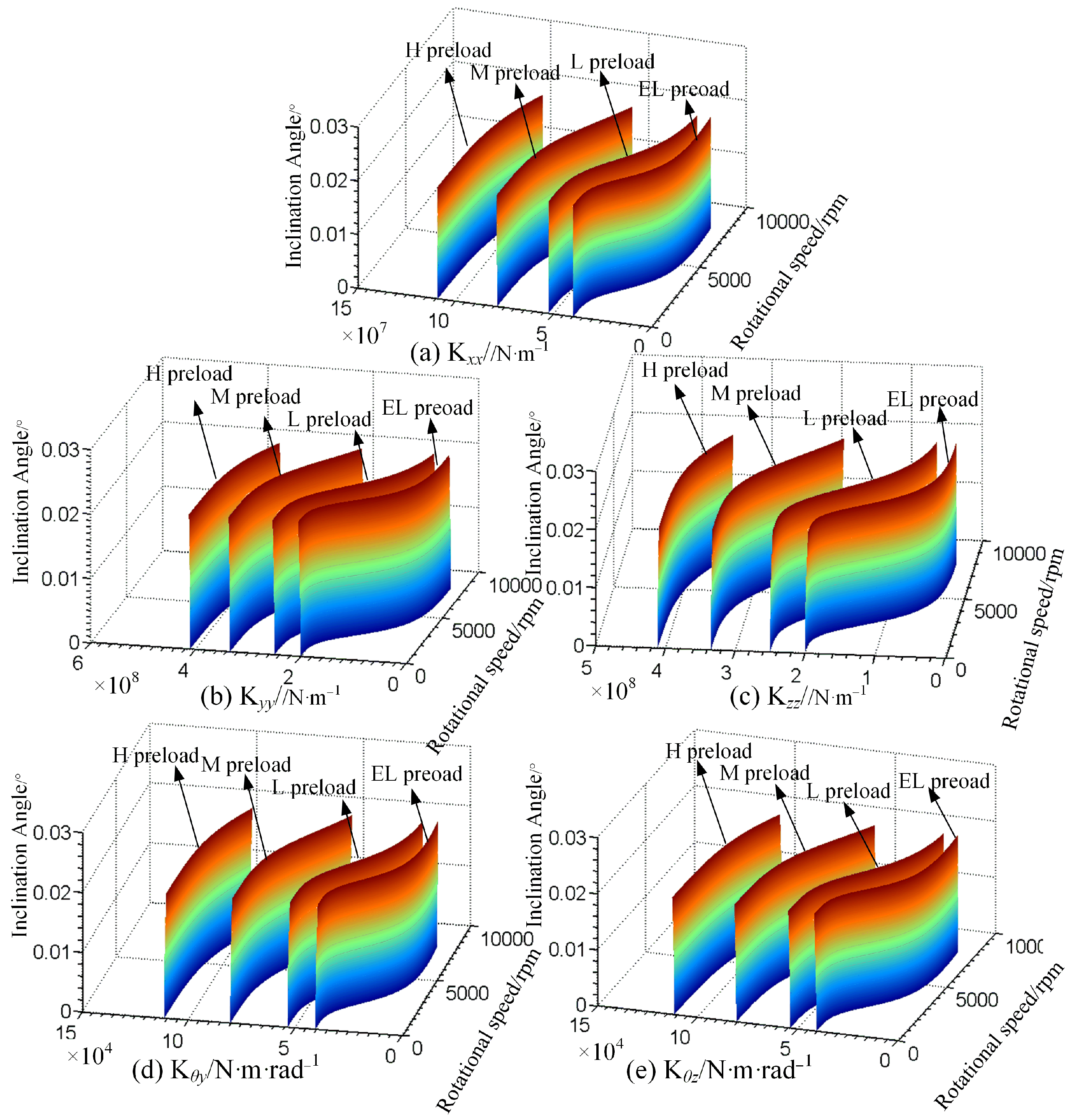
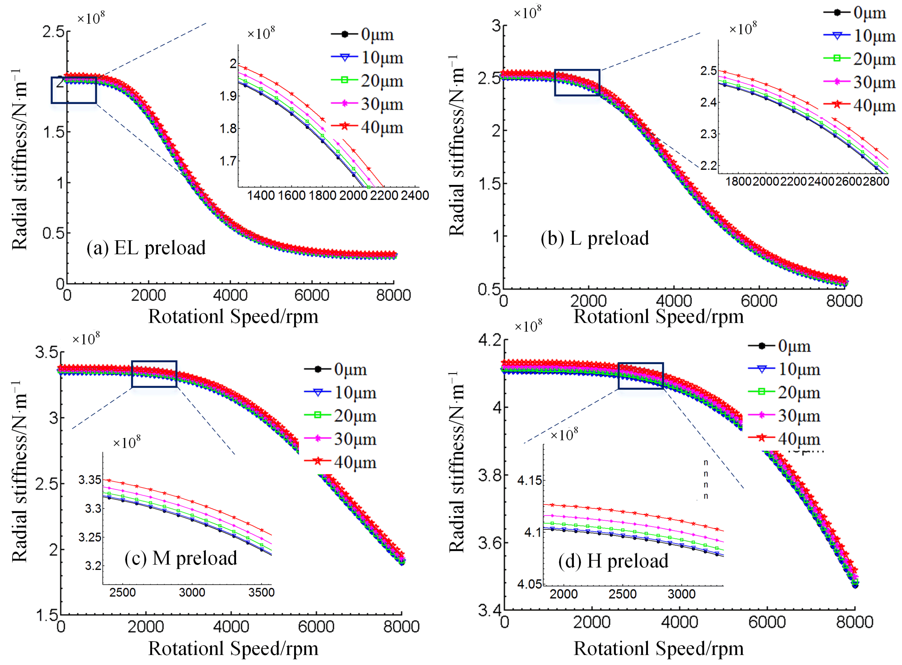
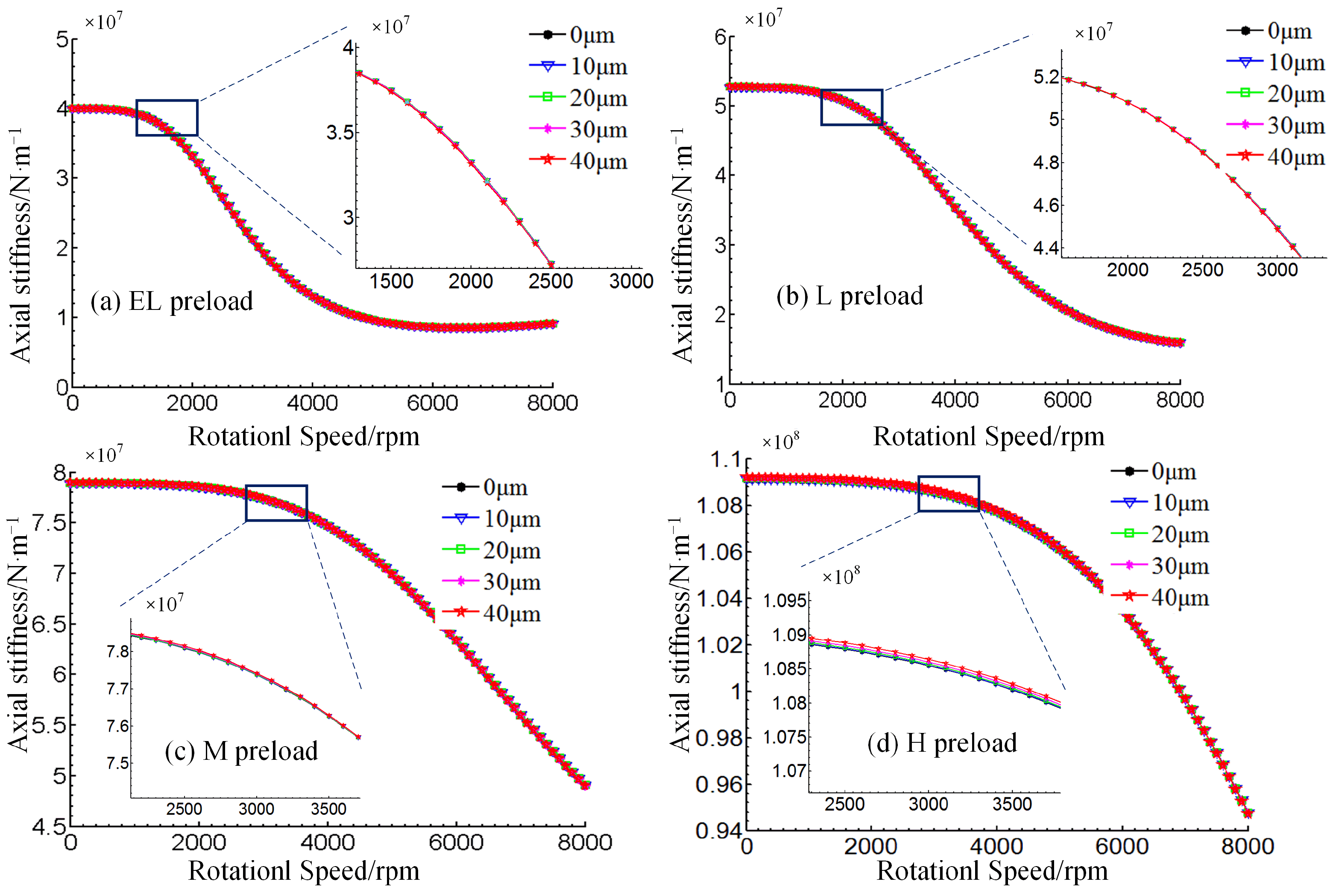
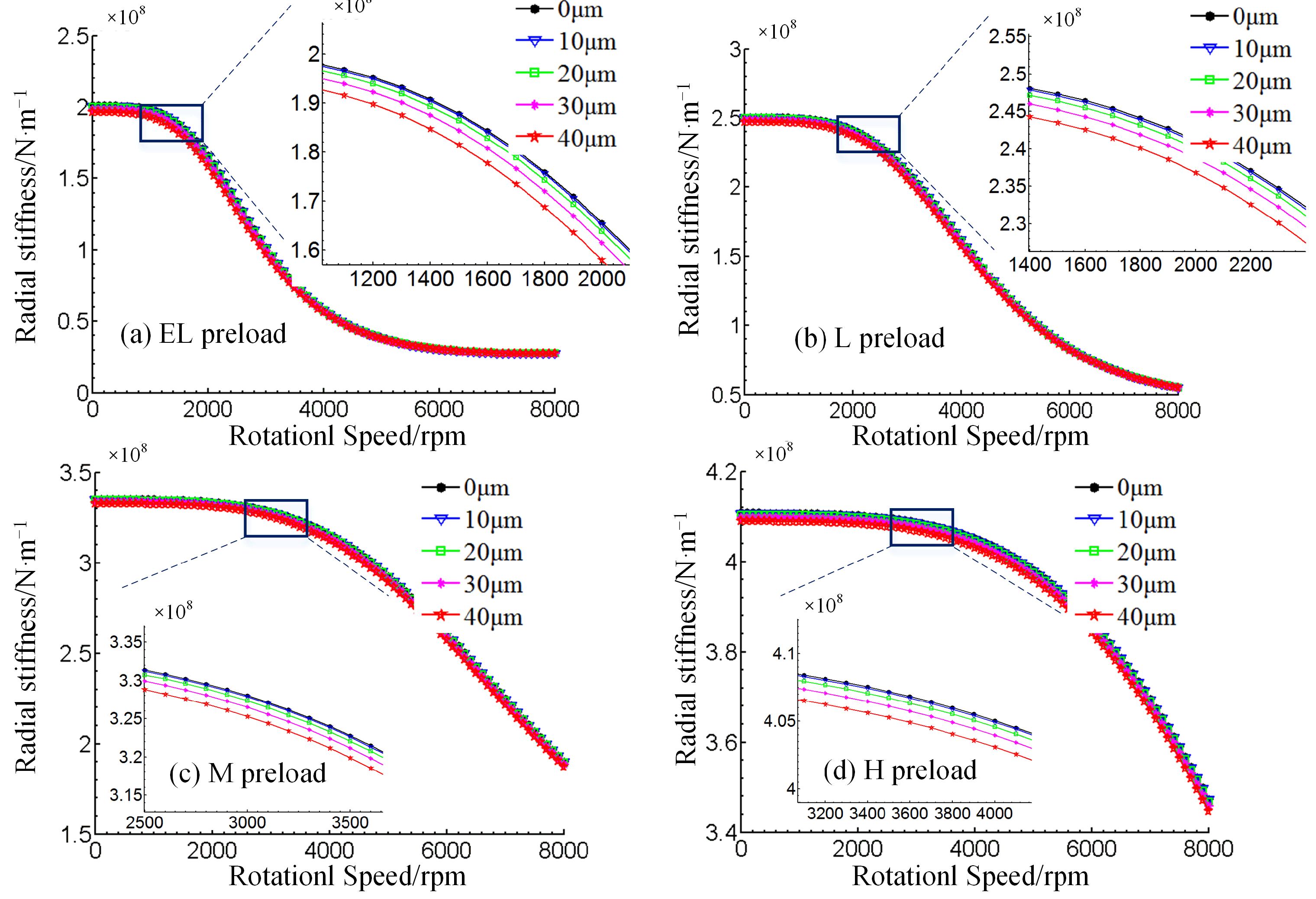
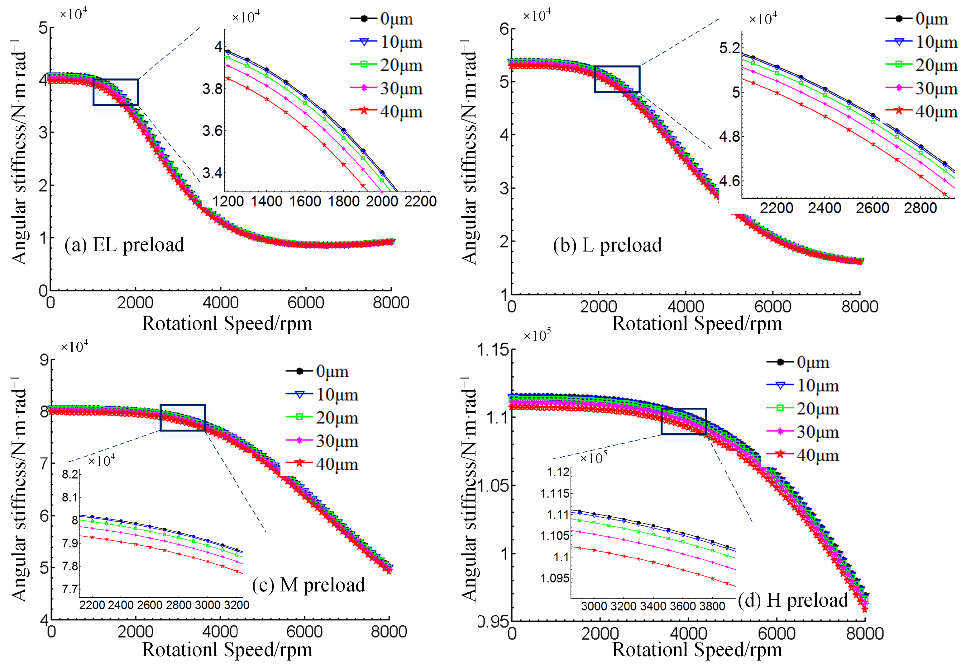
4.2. Analysis of the Variation of Bearing Stiffness in All Directions in Relation to Speed

The stiffness—speed—preload relationship graph, based on variations in the bearing’s inner and outer ring tilt, does not adequately reflect the influence of imperfect mounting on bearing stiffness, as shown in Section 4.1. In engineering, the tilting of inner and outer rings inevitably leads to a change in the internal contact parameters of the bearing. If this tilting angle is known, the change in contact parameters will lead to a change in contact stiffness, until it is reflected in the isotropic stiffness of the bearing. As a result, the effect of the additional bending moment, induced by the relative tilting of the inner and outer rings, on bearing stiffness, will be investigated, in order to further confirm it, based on a two-dimensional plane perspective.
Figure 7 shows the change in the axial stiffness of the bearing, as a function of speed, under various preload forces. It also illustrates a comparison and analysis of the change in axial stiffness of the bearing, as a function of the inner and outer rings inclination value. Based on Figure 5, from a macroscopic point of view, bearing inner and outer ring relative tilt angle variations did not produce too high influence on the axial stiffness. In the operating conditions of Extremely Light preload (EL), Light preload (L), Medium preload (M), bearing stiffness change curve shows obvious consistency, as the five curves almost overlap. In the Heavy preload (H) operating conditions, the axial stiffness difference in the local magnification chart is slightly obvious. However, compared to the bearing axial stiffness value of 1–2 magnitude orders lower, this difference can be ignored. At the same time, another occurrence was specified, namely the considerable change in axial stiffness of the bearing, caused by the preload force. In the mild preload situation, when the speed approaches 1800 rpm, the axial rigidity gradually drops, until stabilizing at 5000 rpm. The slope of the drop is less than that, in the slight preload conditions. Similarly, in the bearing under preload conditions, the stiffness decreases more obviously after the speed reaches about 3000 rpm, while even more obviously in heavy preload conditions, when the axial stiffness only shows a significant decreasing trend, after the speed reaches about 4000 rpm. The investigation of the axial stiffness of bearings, at various degrees of inner and outer ring tilting, reveals that bearing mounting quality has only a minor impact on axial stiffness, as well as confirms the efficacy and significance of bearing preload in enhancing bearing stiffness.
Figure 8 shows how the bearing’s horizontal radial stiffness varies, with relation to preload force, at various tilting angles, while systematically represented in four operating conditions: extremely light preload, light preload, medium preload and heavy preload. The radial stiffness of the bearing exhibits the same regularity as the axial stiffness, while the influence of the preload on the radial stiffness is also significant. At a higher preload, the bearing stiffness becomes more resistant to the “softening phenomenon”, as the speed increases, whereas the radial stiffness is an order of magnitude higher than the axial stiffness. It should be noted that changing the bearing’s inner and outer ring tilt has a significantly greater impact on radial stiffness, i.e., under different preload circumstances, the bearing’s radial stiffness increases with a tilt angle of roughly 2.5% to 3%. This probably occurs due to the bearing inner and outer ring tilt orientation (see Figure 1 for a schematic depiction). As a result, a thorough understanding of the tilt angle’s influence on the radial stiffness, as well as the general and specific laws of bearing stiffness, is critical, not only for accurate bearing stiffness exploration, but also for providing a solid theoretical foundation for subsequent bearing service performance accuracy.
Similar to Figure 8 and Figure 9 shows how the bearing’s vertical radial stiffness varies with relation to preload force, at different tilting angles, represented consistently under four operating conditions: EL, L, M and H. It is proven that the vertical radial stiffness of the bearing shows almost the same regularity as the horizontal radial stiffness, while the difference is reflected in a closer local view, where the horizontal radial stiffness of the bearing appears slightly increased, in an analogy to the increase of the inner and outer ring tilt. In regards to the vertical radial stiffness, the exact opposite relationship holds; that is, the vertical radial stiffness of the bearing decreases with the increase of the tilt angle, at about 2~2.5%. The bearing spacer tilt orientation, generated by this common difference, tilts the bearing about the horizontal axis, according to the analysis. In order to accurately describe the law of tilt angle influence on bearing radial stiffness, besides the bearing tilt angle changes, the bearing tilt process of relative azimuth changes should be considered in a comprehensive analysis, which will provide results that are more in line with the actual engineering reality, while also more accurate.
Figure 7, Figure 8 and Figure 9 illustrate the three directions of the bearing plain stiffness change law. Since angular contact ball bearings also have an angular stiffness, an in-depth analysis should explore whether the bearing inner and outer ring relative tilt will have what effect on the angular stiffness and whether it is still similar to the plain stiffness change law, so as to accurately grasp the overall stiffness change mechanism.
Figure 10 shows that, the angular stiffness of the bearing changes in a similar way to the flatness of the bearing. From a macroscopic perspective, bearing speed and initial preload are the most important factors in determining bearing stiffness. Furthermore, angular stiffness and plain stiffness decrease as frequency increases, and they rise as preload decreases. The fact that the tilt angle of the inner and outer rings vary around the z axis, makes the angular stiffness of the bearing changes, with relation to the tilt angle of the inner and outer rings, a little more visible (Figure 1), so the angular stiffness Kθy decreases as the tilt angle increases.
Based on Figure 11, the angular stiffness Kθz variation characteristics with relation to speed are almost identical to the respective angular stiffness Kθy variation characteristics, whereas minor differences are only reflected in the local view enlargements; however, the effect of the bearing tilt angle is evident in this difference in variation. A comparison of the local enlargements in Figure 8 shows that the angular stiffness Kθy tends to decrease as the angle of inclination increases, while the angular stiffness Kθz tends to increase as the angle of inclination increases, while the greater the preload the more significant the difference is.
Throughout the bearing stiffness curve with relation to speed and the preload force change law, it was discovered that the bearing’s initial preload force, working speed and stiffness performance play dominant roles. However, the bearing inner and outer ring tilt angle, as well as the bearing stiffness in all directions show a significant correlation and a significant regularity difference. Although this variability may have a minor effect on the performance of rough machining spindles, it cannot be overlooked in precision machining spindles. Consequently, while mounting spindle bearings, special attention should be paid to the quality of the installation, ensuring that their stiffness characteristics and even the service performance of the spindle system are carefully controlled.
Due to the numerous elements affecting bearing stiffness fluctuation, a study focused just on the total stiffness under these five tilting scenarios would still yield traditional regularity results. Thus, the bearing stiffness influence must be decomposed into the local area of each rolling element and raceway contact, i.e., the overall rigidity. The bearing’s performance is determined by the specific rolling element, while the stiffness of the inner and outer ring raceways follow a certain law combination, which requires a more complete examination of the local contact unit area.

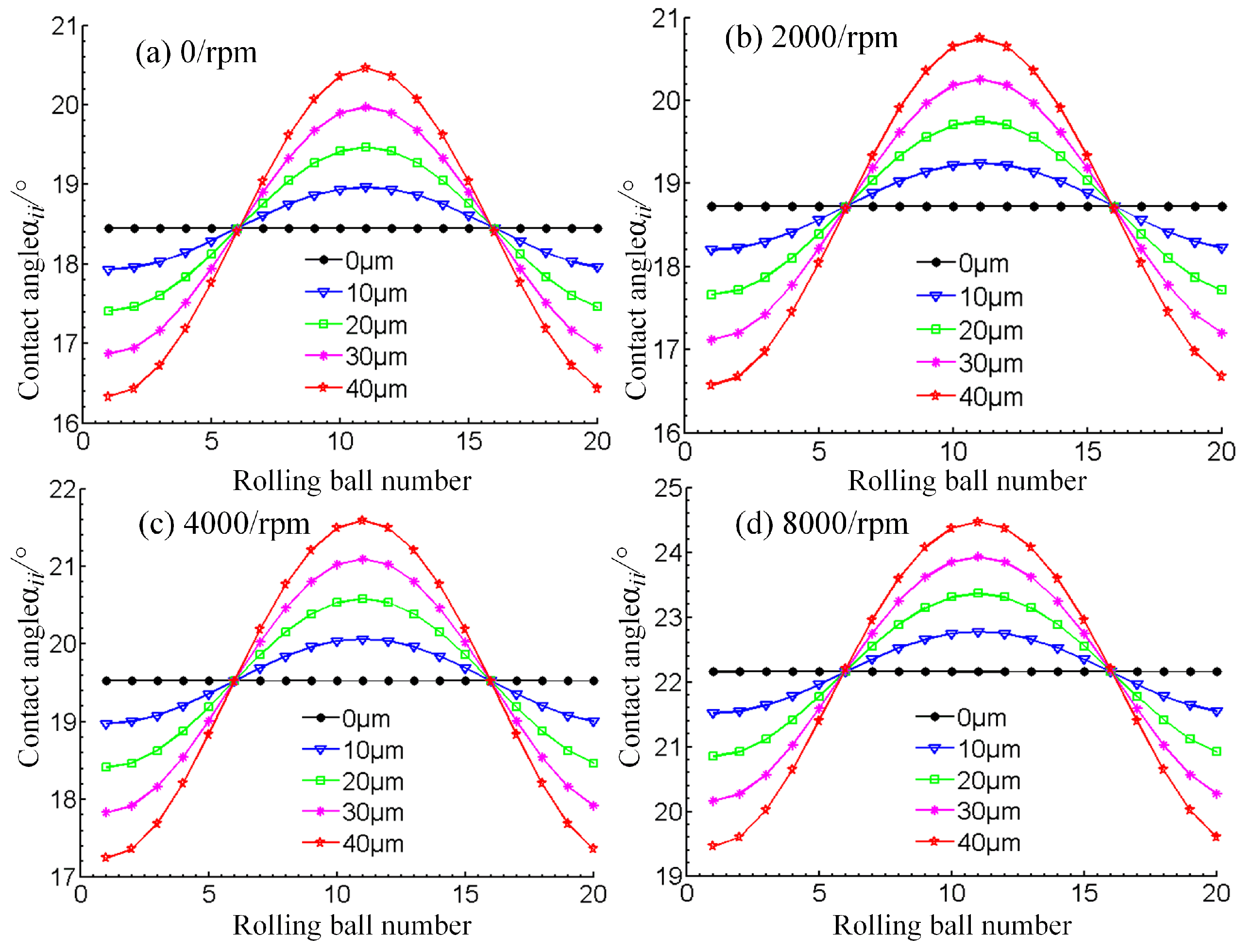
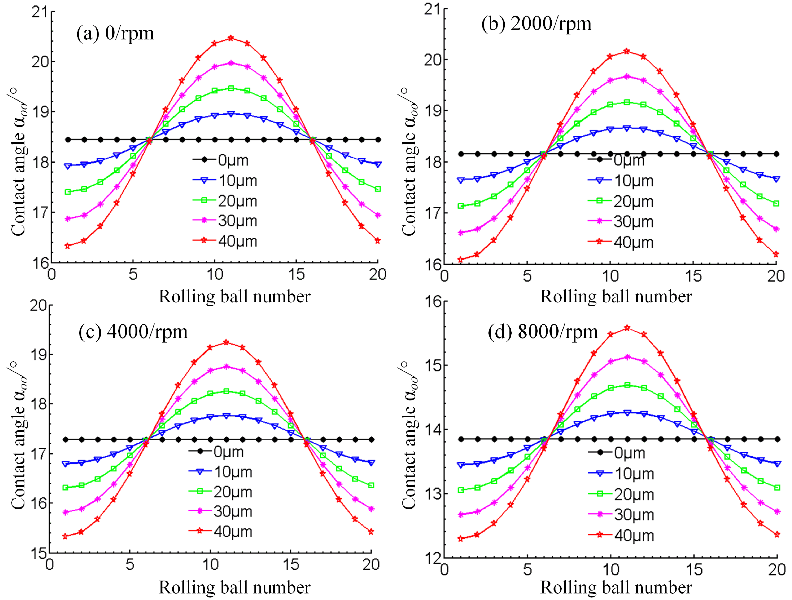
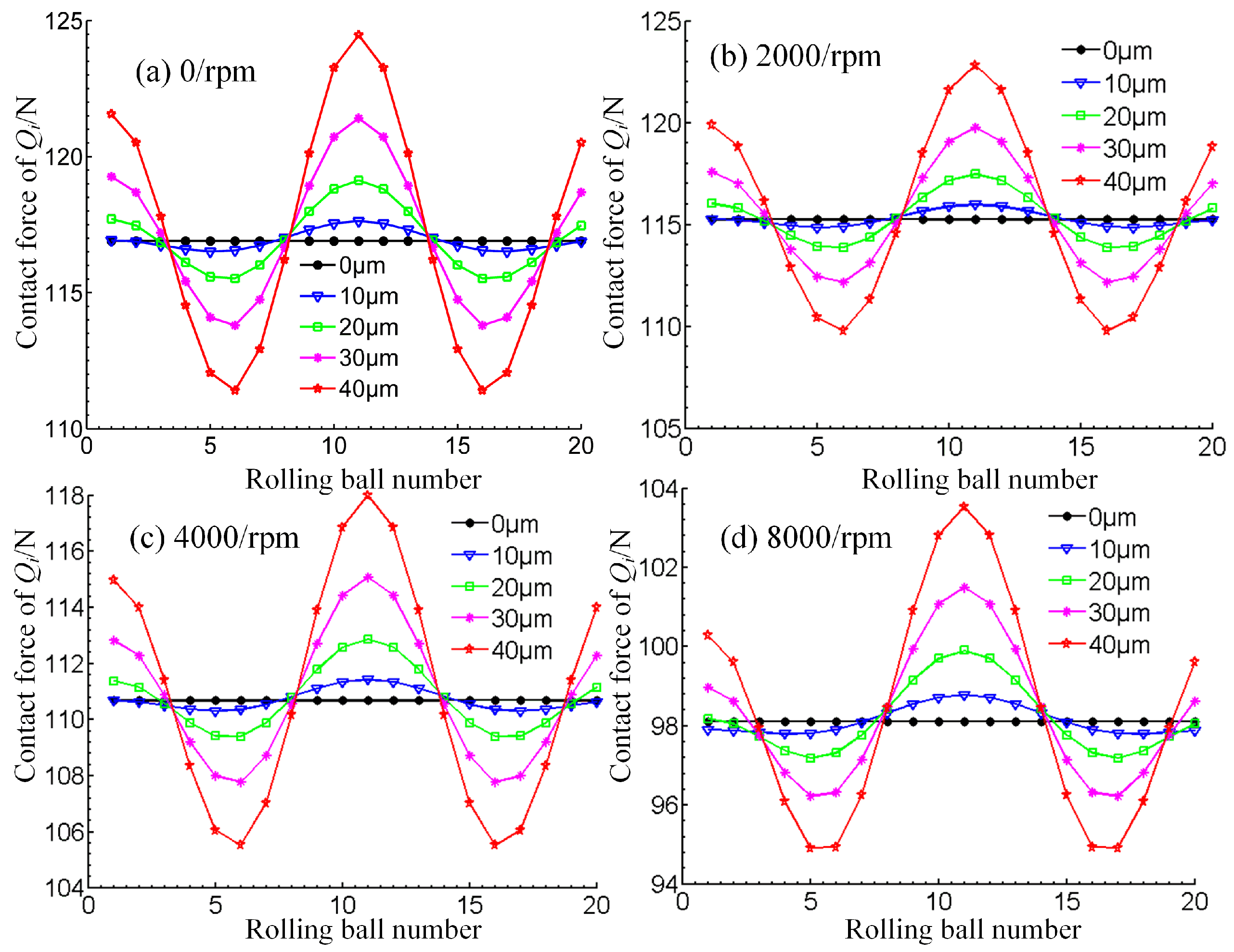
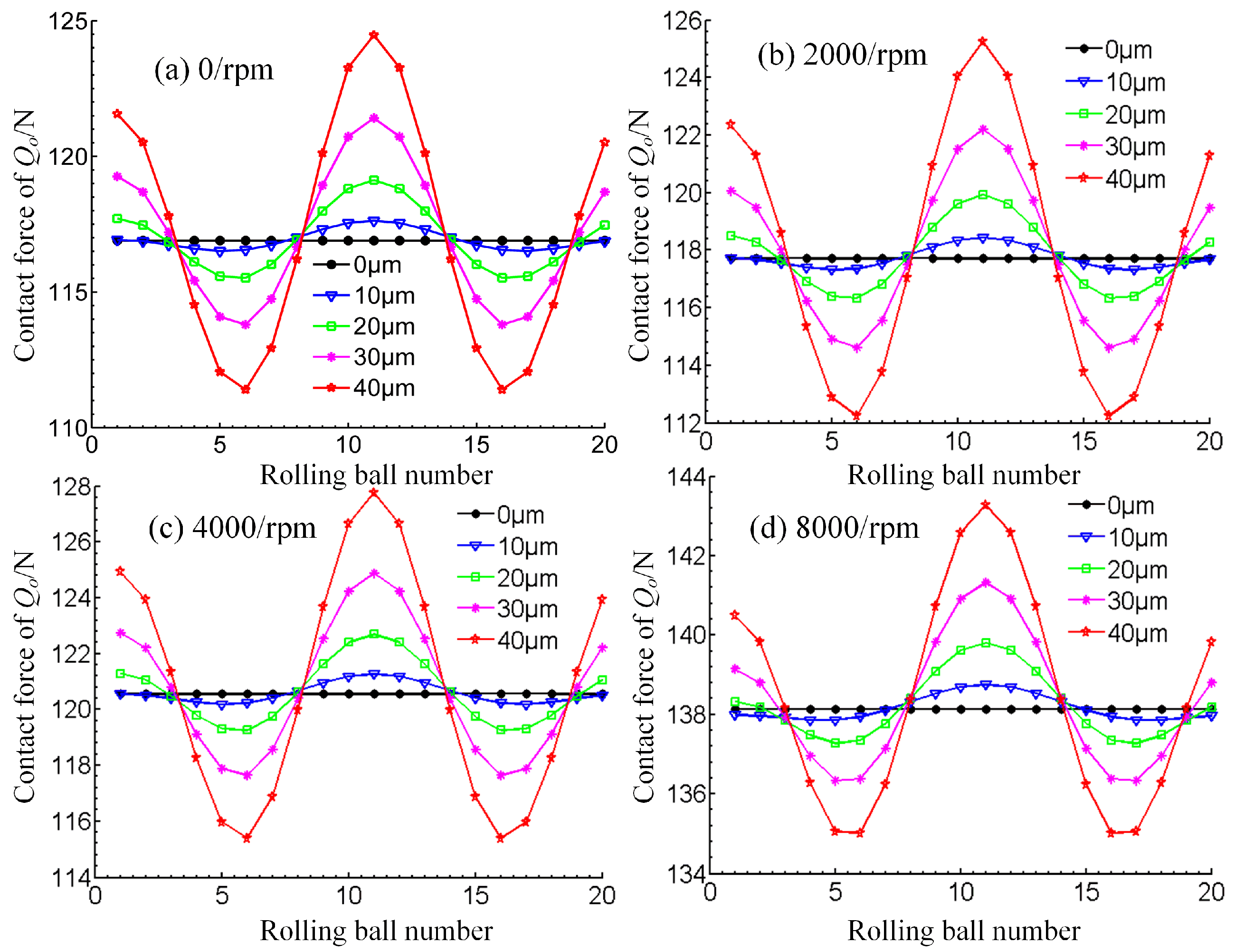
4.3. Analysis of Bearing Stiffness Variability in All Directions

The bearing stiffness in all directions was studied, as well as bearing speed, preload, inner and outer ring tilt working circumstances, which derived that the bearing stiffness is predominantly represented in the radial stiffness. This paper further analyses the inner contact angle αii, outer contact angle αoo, inner ring contact force Qi and outer ring contact force Qo of the rolling element, in addition to the raceway in the local area of the bearing, carrying out numerical research on the internal contact mechanical properties of the bearing. Since the general law of the bearing is the same for different preload values, only the medium preload condition, which is typically employed in engineering, is selected as a representative case for the specific analysis, whereas the variation of the bearing’s internal contact characteristics is also investigated.
The characteristics of the 7014C bearing, under the influence of the inner and outer ring tilt rolling inner contact angle change, are shown in Figure 12. The inner contact angle gradually increases, as the speed rises, which is mostly due to the bearing’s centrifugal force gradually increasing along the speed rise. At a constant speed, the analysis of the curve can provide certain results. Specifically, when the bearing inner and outer ring tilt is 0, each ball contact angle is a constant value (the impact of the bearing rolling body own weight is not considered). When the inner and outer rings show a certain tilt, the contact angle is then changed and some rolling body at the contact angle increased and some become smaller, while with the bearing inner and outer ring tilt degree of intensification, the difference of inner contact angle on individual balls is also increased. As the contact angle variations will affect the bearing performance, these will inevitably have a certain impact on the overall bearing rigidity.
Figure 13 shows the characteristics of the 7014C shaft at four different speed values, demonstrating the effect of the inner and outer ring tilt on the rolling element’s outer contact angle. It becomes evident that the outer contact angle of the bearing decreases as the speed increases; a phenomenon due to the centrifugal effect, caused by the speed change. Moreover, the difference between the outer contact angles of each rolling element shows an obvious tendency.
In Figure 14, the variation of the local contact force, between the rolling element and raceway of the inner ring of the bearing, is depicted. It can be seen that when the bearing speed increases, the inner ring local maximum contact force changes with the inner ring contact angle, while with the increase of speed the inner ring maximum local contact force significantly decreases. The main reason is that the contact angle increases along with the speed, which reduces the maximum local contact force. Under the same speed, the maximum local contact force changes more significantly with the increase of the inner and outer ring tilt angle. This indicates that when the tilt amount increases, the impact on the internal contact parameters of the bearing is more significant, intensifying the uneven load on the contact area of each rolling element of the bearing, whereas the unevenly distributed contact force on the circumferential radial is one of the reasons for the non-uniformity of the radial stiffness of the bearing, which may have a great impact on the accuracy and even the service life of the bearing.
Figure 15 illustrates the variation pattern of the bearing outer ring contact force. It can be seen that, the bearing outer ring contact force exhibits a similar pattern to the bearing inner ring contact force. The difference lies in the speed rise causing the contact force on the outer ring of the bearing to increase. The change is still related to the increasing speed, caused by the effect of centrifugal force. At a certain speed, the outer ring local contact force changes. This means that the contact force on the outer ring of the bearing is non-uniform, along the circumferential direction, while this non-uniformity increases with the amount of skew.

5. Conclusions

In view of the common problems of bearing mounting in actual working conditions, the bad assembly state is simplified and represented by the relative tilting of the bearing spacer. Then, the influence of bearing preload, rotation speed and tilting of the spacer on the stiffness, along all directions, is examined the bearing stiffness (radial, axial and angular) is comparatively discussed under different assembly conditions, as well as the bearing preload and rotation speed. The main conclusions of this paper are as follows:
  • Bearing inner and outer ring tilt angle has a greater impact on bearing radial stiffness than on axial stiffness.
  • The inner and outer rings of the bearing changes lead to variations of the inner ring contact load, revealing the reasons for the bearing’s anisotropic stiffness.
  • Among the three influence factors of bearing preload, rotational speed and spacer inclination, although the inclination has the smallest influence on the macroscopic stiffness of the bearing, it will cause uneven radial stiffness of the bearing, which is very important for a precision spindle.
  • Moreover, the anisotropy of radial stiffness, caused by the inclination of the bearing spacer, will be verified through experiments in the follow-up research. In the future, the study on the precision spindle system stiffness, induced by bearing anisotropy of radial stiffness, will be exhaustive.

Author Contributions

Conceptualization, Y.Z. and Y.L.; methodology, Y.L.; validation, Y.Z., Y.L. and L.K.; formal analysis, Z.Y. and Y.S.; investigation, L.K. and Y.Z.; data curation, Y.L.; writing—original draft preparation, Y.S.; writing—review and editing, Y.L.; visualization, Y.S.; supervision, Y.S.; project administration, Z.Y.; and funding acquisition, Y.S. All authors have read and agreed to the published version of the manuscript.

Funding

This research was funded by National Natural Science Foundation of China, grant number 52005405, General project of Shaanxi Natural Science Foundation, grant number 2022JM-244 and Natural Science Basic Research Program of Shaanxi Province, grant number 2020JQ-639.

Institutional Review Board Statement

Not applicable.

Informed Consent Statement

Not applicable.

Data Availability Statement

Detailed data are contained within the article.

Conflicts of Interest

The authors declared no potential conflict of interest with respect to the research, authorship, and/or publication of this article.

References

  1. Wan, C.S. Analysis Method of Rolling Bearing; China Machanical Press: Beijing, China, 1995. (In Chinese) [Google Scholar]
  2. Yang, Z.; Li, C.; Zhou, N.; Zhang, J. Research on the cage stability of high-precision ball bearing with image acquirement and error separation. Measurement 2021, 186, 110149. [Google Scholar] [CrossRef]
  3. Sier, D.; Xinglin, L.; Jiugen, W. Frictional torque characteristics of angular contact ball bearings. J. Mech. Eng. 2011, 47, 114–120. [Google Scholar]
  4. Yang, Z.; Niu, X.; Li, C. Experimental study on cage dynamic behavior of long-life high-precision ball bearing with trajectory deviation. IEEE Trans. Instrum. Meas. 2022, 71, 5011511. [Google Scholar] [CrossRef]
  5. Liu, J.; Tang, C.; Wu, H.; Xu, Z.; Wang, L. An analytical calculation method of the load distribution and stiffness of an angular contact ball bearing. Mech. Mach. Theory 2019, 142, 103597. [Google Scholar] [CrossRef]
  6. Abele, E.; Altintas, Y.; Brecher, C. Machine tool spindle units. CIRP Ann 2010, 59, 781–802. [Google Scholar] [CrossRef]
  7. Lin, C.-W.; Lin, Y.-K.; Chu, C.-H. Dynamic models and design of spindle-bearing systems of machine tools: A review. Int. J. Precis. Eng. Manuf. 2013, 14, 513–521. [Google Scholar] [CrossRef]
  8. Ma, S.; Zhang, X.; Yan, K.; Zhu, Y.; Hong, J. A Study on Bearing Dynamic Features under the Condition of Multiball–Cage Collision. Lubricants 2022, 10, 9. [Google Scholar] [CrossRef]
  9. Gao, S.H.; Meng, G.; Long, X.H. Study of milling stability with Hertz contact stiffness of ball bearings. Arch. Appl. Mech. 2011, 81, 1141–1151. [Google Scholar] [CrossRef]
  10. Jones, A.B. A general theory for elastically constrained ball and radial roller bearings under arbitrary laod and speed conditions. J. Basic Eng. 1960, 82, 309–320. [Google Scholar] [CrossRef]
  11. Harris, T.A. Rolling Bearing Analysis, 4th ed.; John Wiley and Sons, Inc.: New York, NY, USA, 2000. [Google Scholar]
  12. Jedrzejewski, J.; Kwasny, W. Modelling of angular contact ball bearings and axial displacements for high-speed spindles. CIRP Ann. 2010, 59, 377–382. [Google Scholar] [CrossRef]
  13. Rantatalo, M.; Aidanpaa, J.-O.; Göransson, B. Milling machine spindle analysis using fem and non-contact spindle excitation and response meaure-ment. Int. J. Mach. Tools Manuf. 2007, 47, 1034–1045. [Google Scholar] [CrossRef]
  14. Sheng, X.; Li, B.; Wu, Z.; Li, H. Calculation of ball bearing speed-varying stiffness. Mech. Mach. Theory 2014, 81, 166–180. [Google Scholar] [CrossRef]
  15. Noel, D.; Ritou, M.; Furet, B.; Le Loch, S. Complete Analytical Expression of the Stiffness Matrix of Angular Contact Ball Bearings. J. Tribol. 2013, 135, 041101. [Google Scholar] [CrossRef]
  16. Guo, Y.; Parker, R.G. Stiffness matrix calculation of rolling element bearings using a finite element contact mechanics model. Mech. Mach. Theory 2012, 51, 32–45. [Google Scholar] [CrossRef]
  17. Cao, H.R.; Tomas, H.; Yusuf, A. A comparative study on the dynamics of high speed spindles with respect to different preload mechanisms. Int. J. Adv. Manuf. Technol. 2011, 57, 871–883. [Google Scholar] [CrossRef]
  18. Aramaki, H.; Shoda, Y.; Morishita, Y.; Sawamoto, T. The performance of ball bearing with silicon nitride ceramic balls in high speed spindles for machine tools. ASME J. Tribol. 1988, 10, 693–698. [Google Scholar] [CrossRef]
  19. Yang, Z.W.; Yin, G.F.; Sang, X.; Jiang, H.; Zhong, K.Y. Coupling Analysis Model of Thermal and Dynamic Characteristics for High-speed Motorized Spindle. J. Jilin Univ. (Eng. Technol. Ed.) 2011, 41, 205–210. [Google Scholar]
  20. Liu, X.; Hong, J.; Zhu, Y.S.; Liu, Z. Iterative Method to Solve Bearing’s Force and Stiffness for a Multi-support Spindle System Based on Finite Element Analysis. J. Xi’an Jiaotong Univ. 2010, 44, 41–45. [Google Scholar]
  21. Stone, B.J.; Walford, T. The measurement of the radial stiffness of rolling element bearings under oscillating conditions. J. Mech. Eng. Sci. 1980, 22, 175–181. [Google Scholar]
  22. Kraus, J.; Blech, J.; Braun, S. In situ determination of rolling bearing stiffness and damping by modal analysis. J. Vib. Acoust. Stress Reliab. Des. 1987, 109, 235–240. [Google Scholar] [CrossRef]
  23. Marsh, E.R.; Yantek, D.S. Experimental Measurement of Precision Bearing Dynamic Stiffness. J. Sound Vib. 1997, 202, 55–66. [Google Scholar] [CrossRef]
  24. Zhang, Y.; Fang, B.; Kong, L.; Li, Y. Effect of the ring misalignment on the service characteristics of ball bearing and rotor system. Mech. Mach. Theory 2020, 151, 103889. [Google Scholar] [CrossRef]
  25. Xu, T.; Yang, L.; Wu, W.; Wang, K. Effect of angular misalignment of inner ring on the contact characteristics and stiffness coefficients of duplex angular contact ball bearings. Mech. Mach. Theory 2021, 157, 104178. [Google Scholar] [CrossRef]
  26. Zhang, X.; Han, Q.; Chu, F. Contact angle of ball bearings based on a simplified Jones-Harris method. J. Vib. Shock 2013, 170, 175. [Google Scholar]
Figure 1. Diagram of the forces on the bearing assembly: (a) Bearing spacer titling diagram, (b) Schematic diagram of the Load on the inner/outer rings of the bearing.
Lubricants 10 00116 g001
Figure 2. Flow diagram for calculation of bearing stiffness characteristics in all directions.
Lubricants 10 00116 g002
Figure 3. Graphical depiction of spacer end face non-parallelism.
Lubricants 10 00116 g003
Figure 4. Force analysis diagram of bearing outer ring under inclined spacer ring: (a) contact between bearing and spacer, (b) bearing force, (c) ball orientation diagram.
Lubricants 10 00116 g004
Figure 5. Variation of spindle bearing stiffness in all directions in relation to tilt angle.
Lubricants 10 00116 g005
Figure 6. Variation of spindle bearing stiffness in all directions under preload conditions.
Lubricants 10 00116 g006
Figure 7. Variation of axial bearing stiffness Kxx in relation to speed.
Lubricants 10 00116 g007
Figure 8. Variation of horizontal radial bearing stiffness Kyy with relation to speed.
Lubricants 10 00116 g008
Figure 9. Bearing vertical radial stiffness Kzz variation with relation to speed.
Lubricants 10 00116 g009
Figure 10. Variation of angular bearing stiffness Kθy with relation to speed.
Lubricants 10 00116 g010
Figure 11. Variation of angular bearing stiffness Kθz with relation to speed.
Lubricants 10 00116 g011
Figure 12. 7014C bearing rolling body and raceway internal contact angle αii.
Lubricants 10 00116 g012
Figure 13. 7014C bearing rolling body and the inner contact angle of the raceway αoo.
Lubricants 10 00116 g013
Figure 14. 7014C bearing rolling body and raceway internal contact force Qi.
Lubricants 10 00116 g014
Figure 15. 7014C bearing rolling body and raceway external contact force Qo.
Lubricants 10 00116 g015
Table 1. Basic bearing parameters.
ParameterValue
Db (mm)11.9
fi (mm)0.52
fo (mm)0.52
Z20
dm (mm)90.5
α0 (°)15
Eball (Mpa)
ρball (kg·mm3)
2.06 × 10⁵
7.8 × 10⁻⁶
vball0.3
Ering (Mpa)2.06 × 10⁵
vring0.3
Table 2. Description of bearing stiffness analysis conditions.
PreloadExtremely Light Preload
(EL)
Light Preload
(L)
Medium Preload
(M)
Heavy Preload
(H)
0 μm/0°145 N290 N740 N1470 N
10 μm/0.0052°145 N290 N740 N1470 N
20 μm/0.0104°145 N290 N740 N1470 N
30 μm/0.0156°145 N290 N740 N1470 N
40 μm/0.0208°145 N290 N740 N1470 N
Publisher’s Note: MDPI stays neutral with regard to jurisdictional claims in published maps and institutional affiliations.

