Characteristics of a Surgical Snare Using Microwave Energy


Abstract
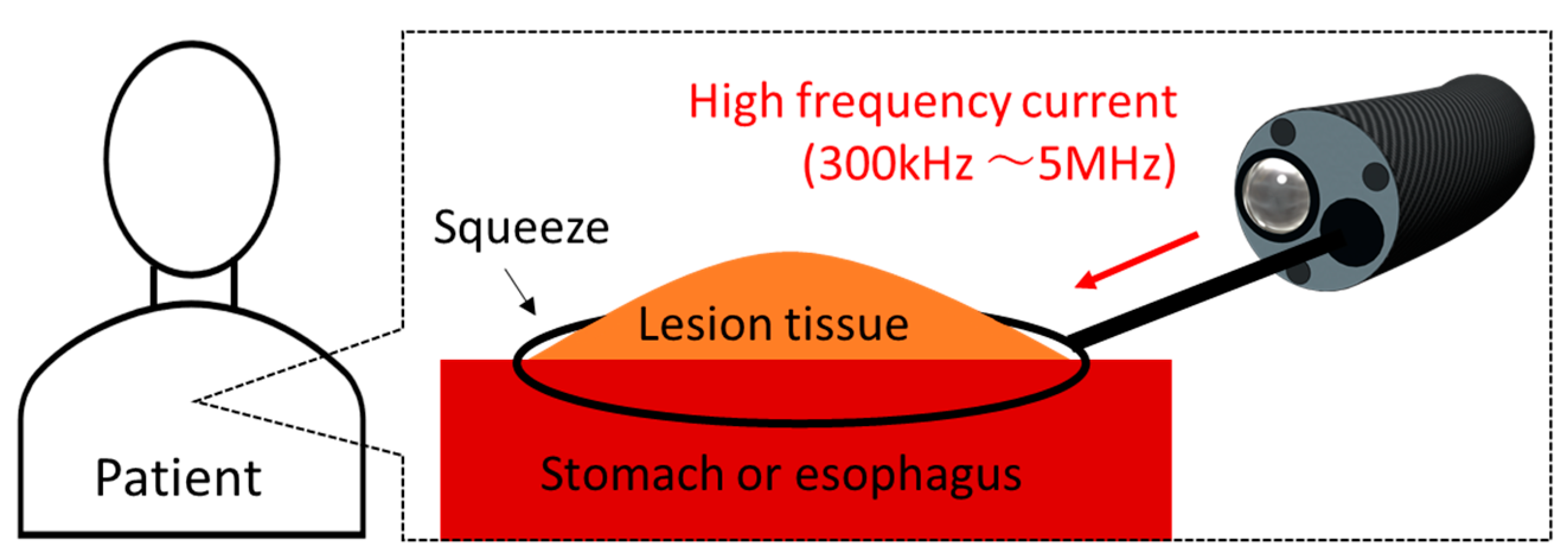
:1. Introduction
2. Materials and Methods
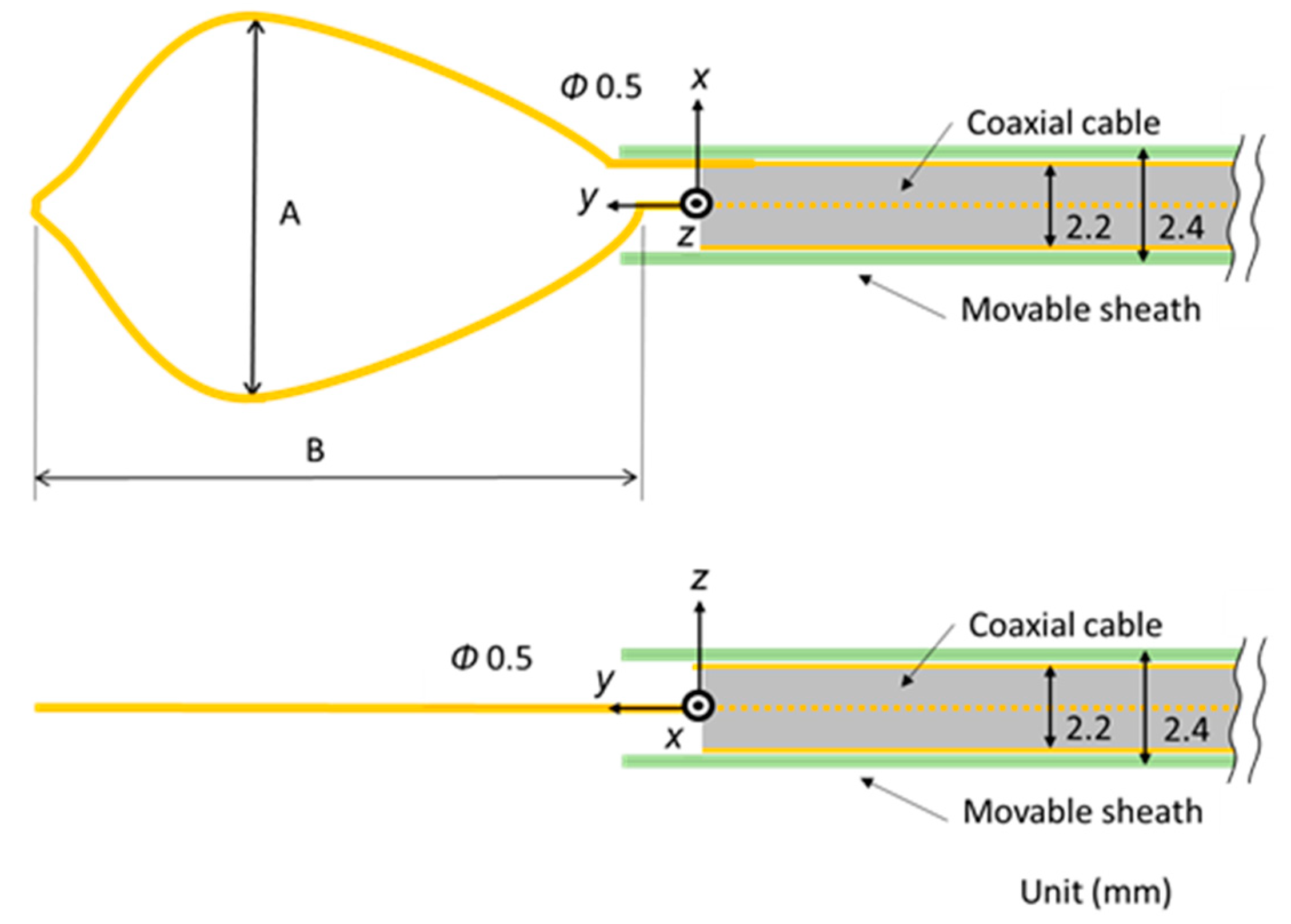
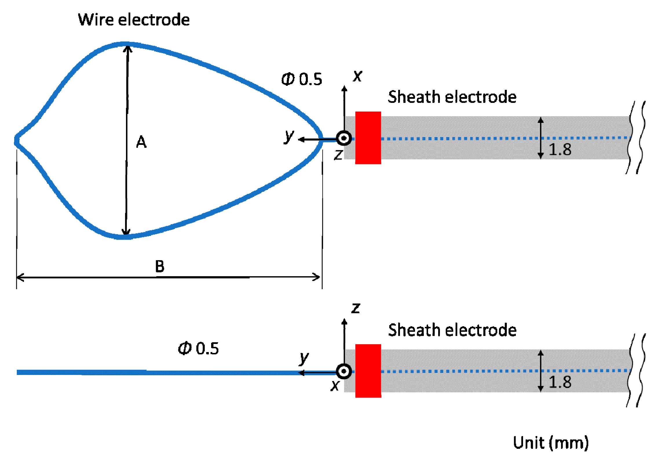
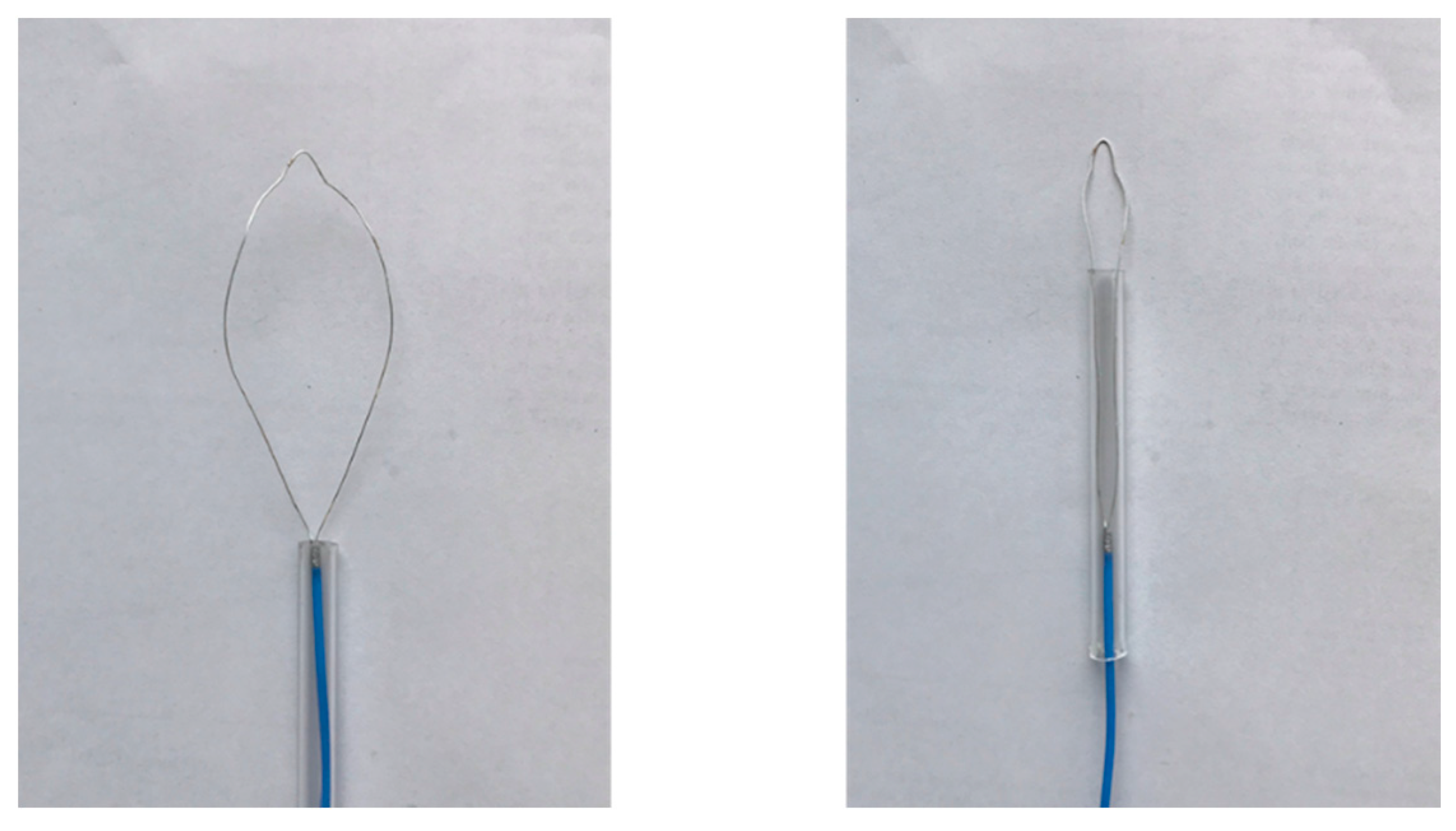
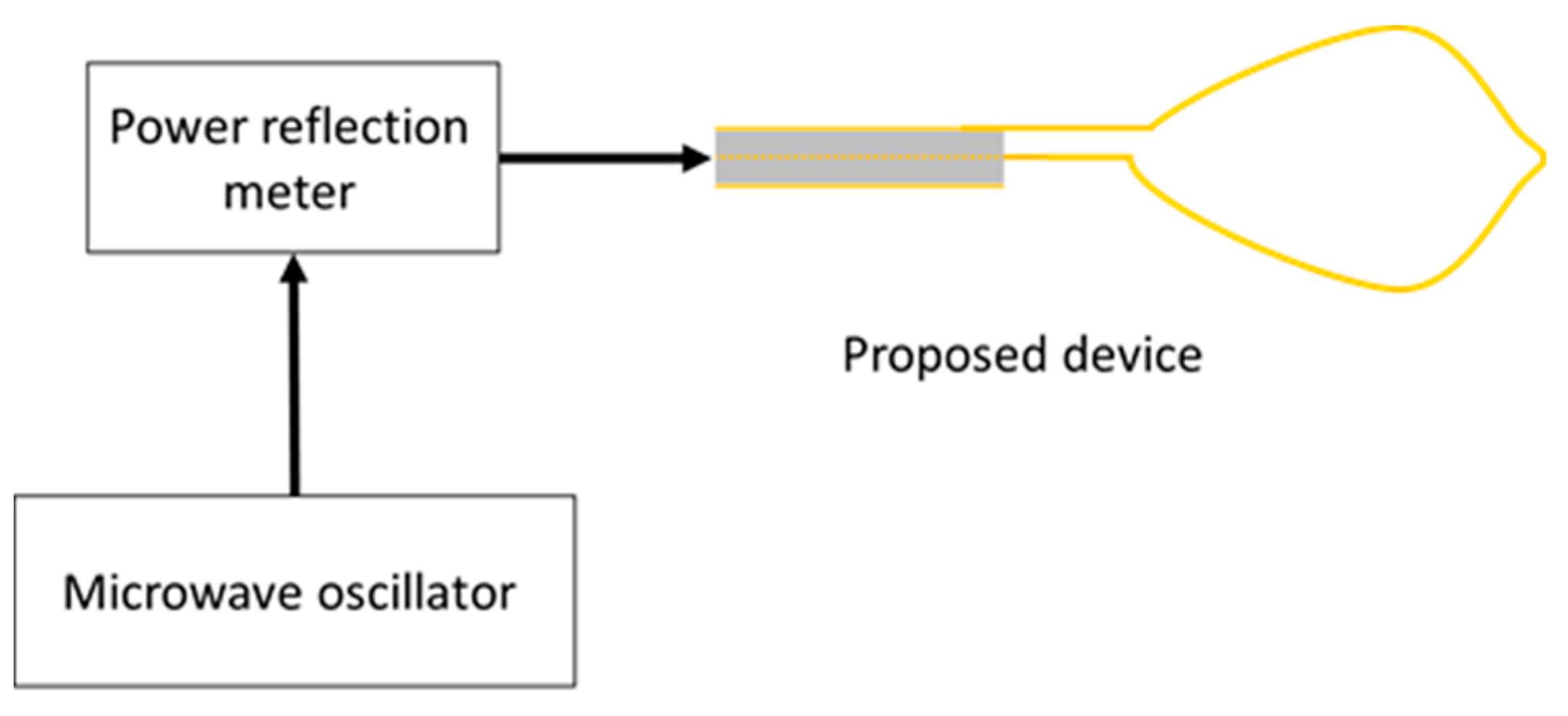
2.1. Device Structure
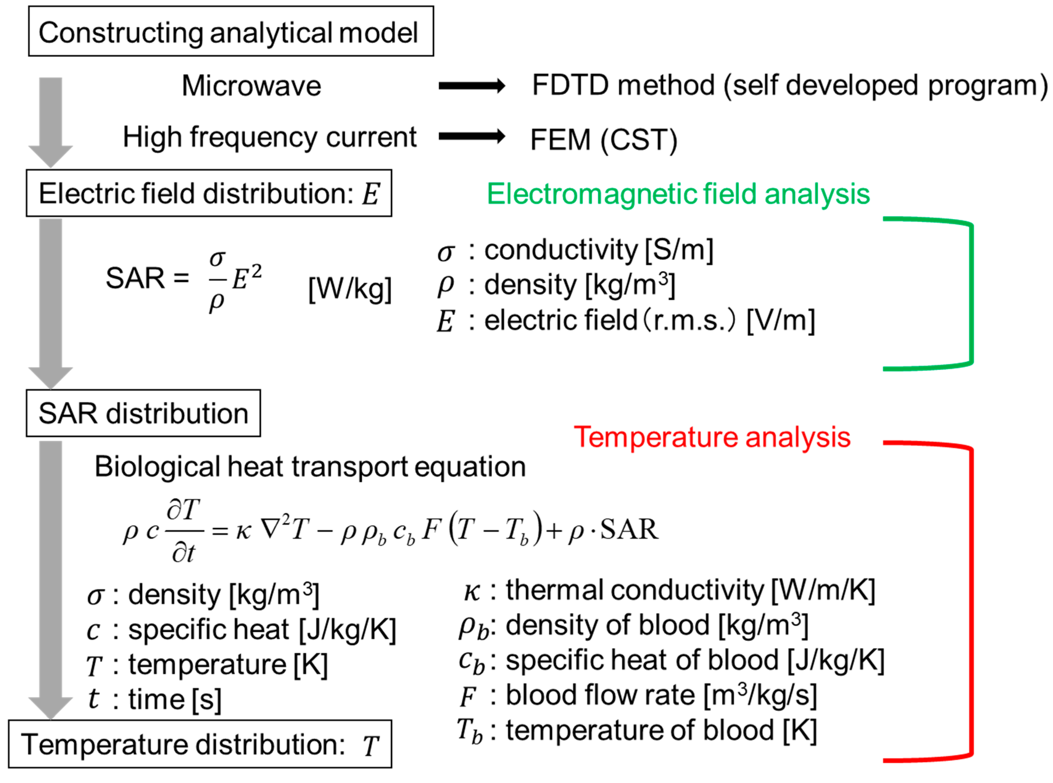
2.2. Electromagnetic Field Analysis
2.3. Temperature Analysis
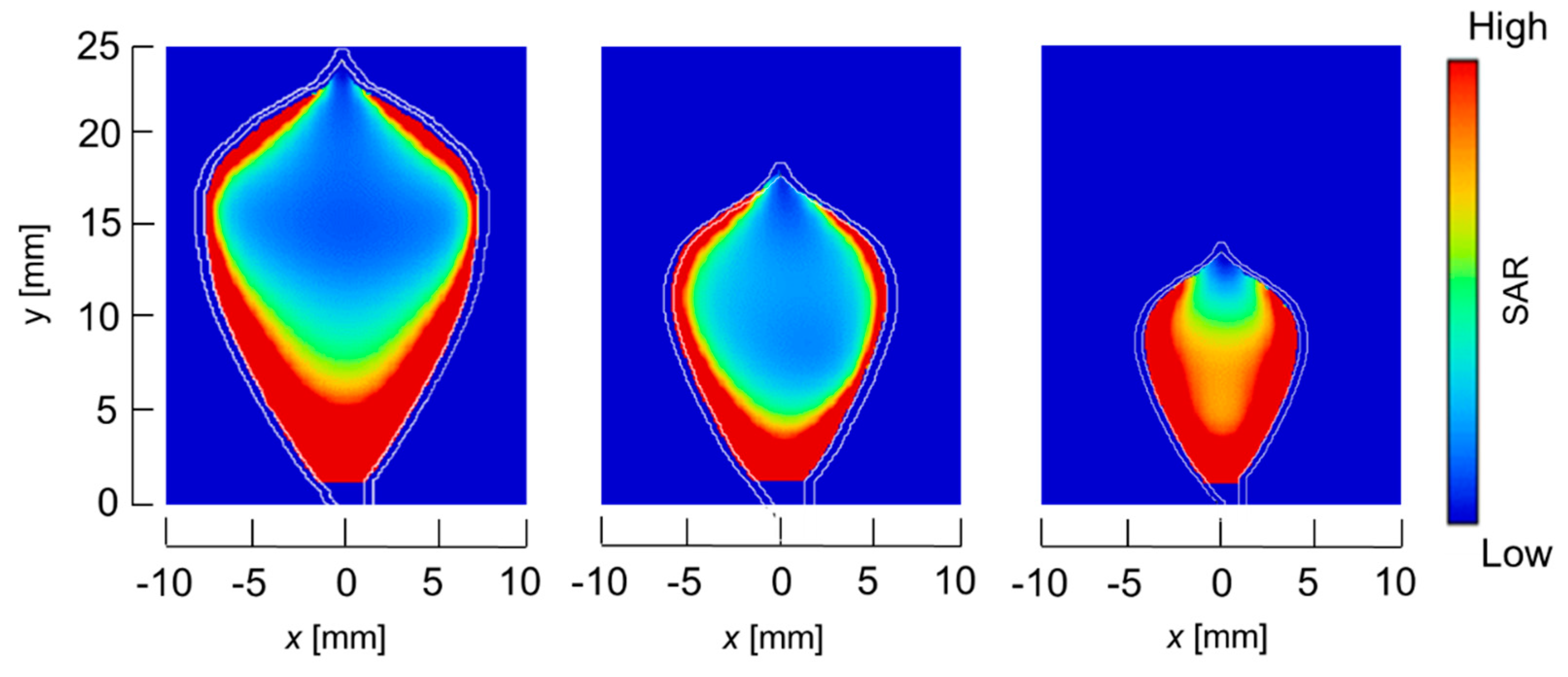
3. Results
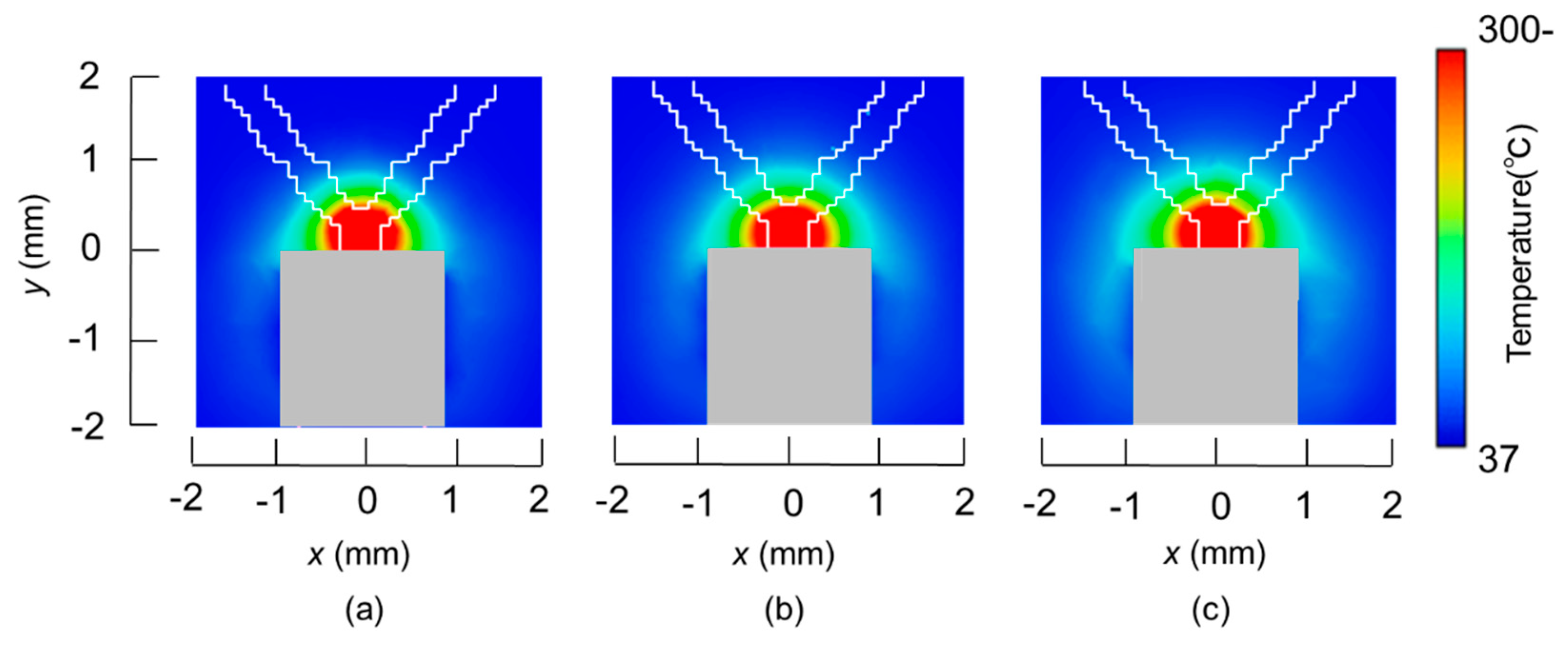
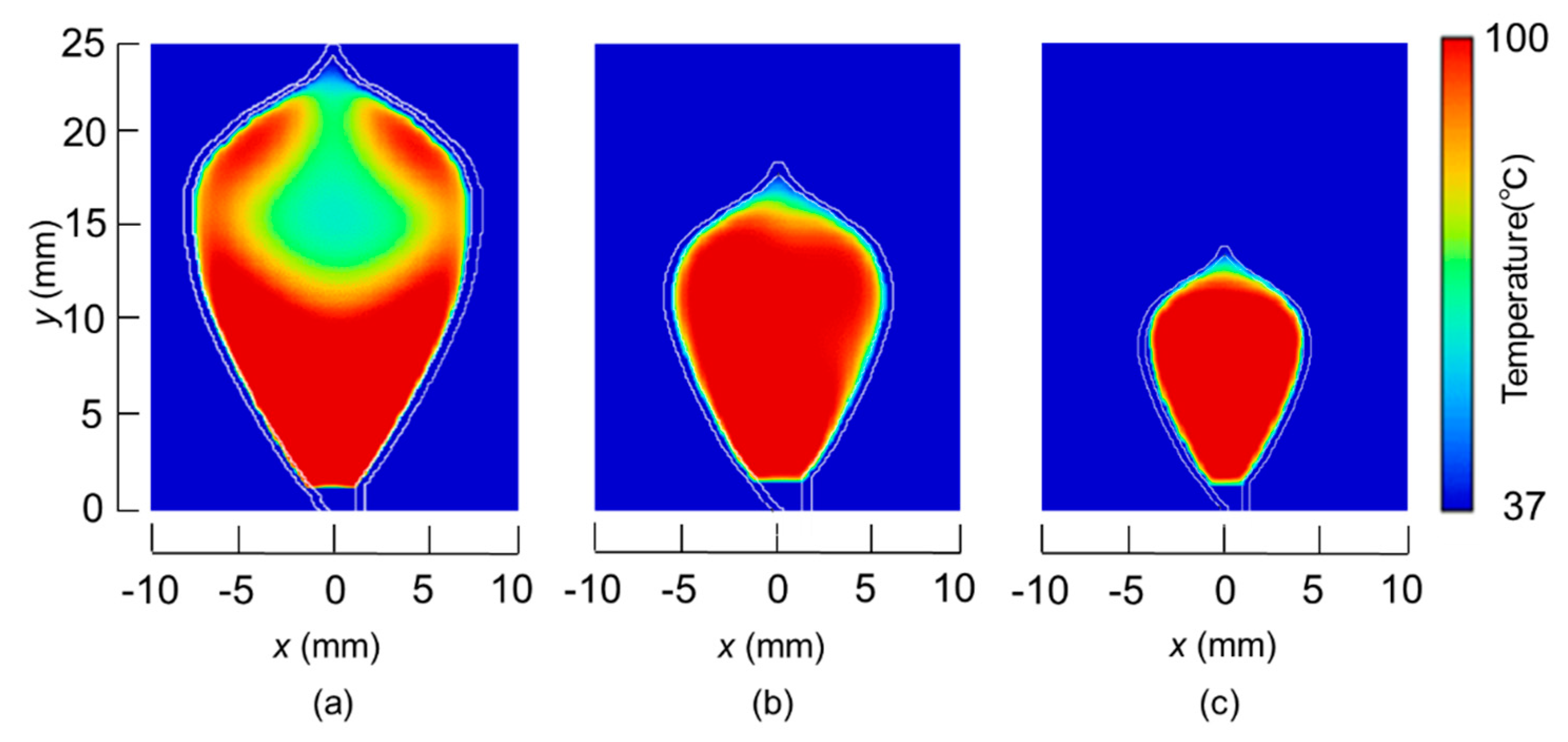
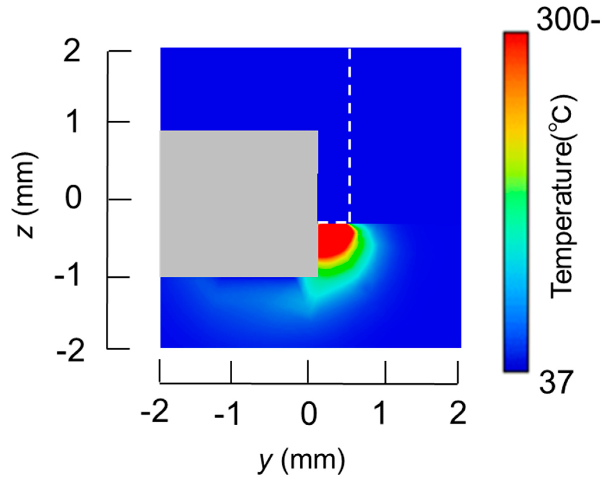
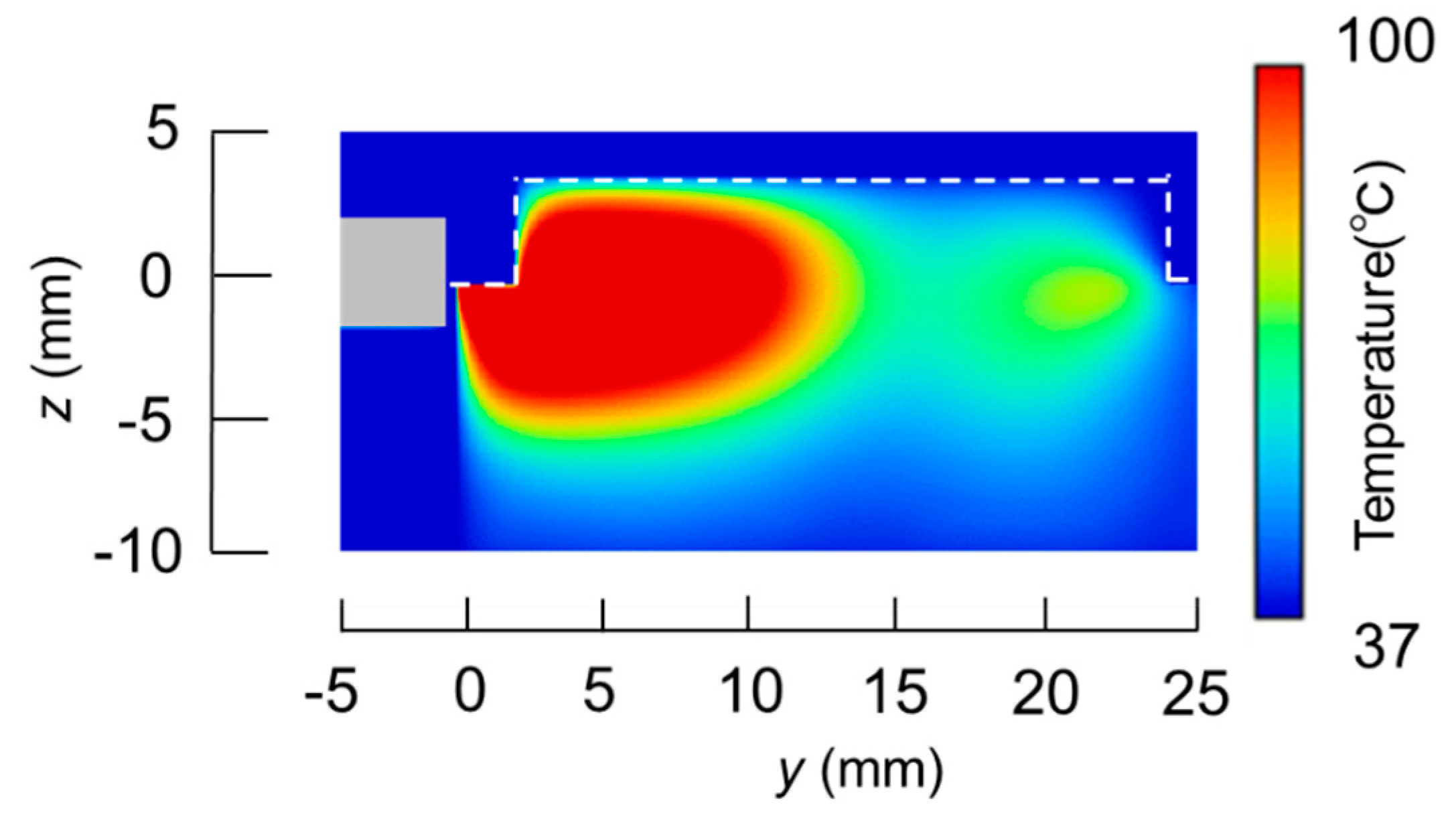
3.1. Calculated Results
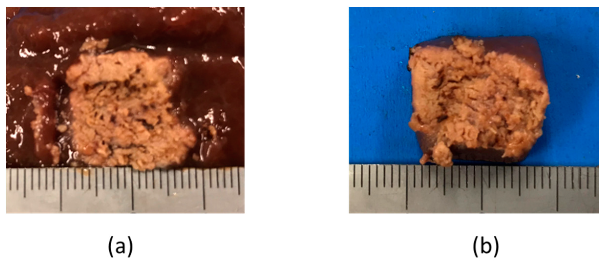
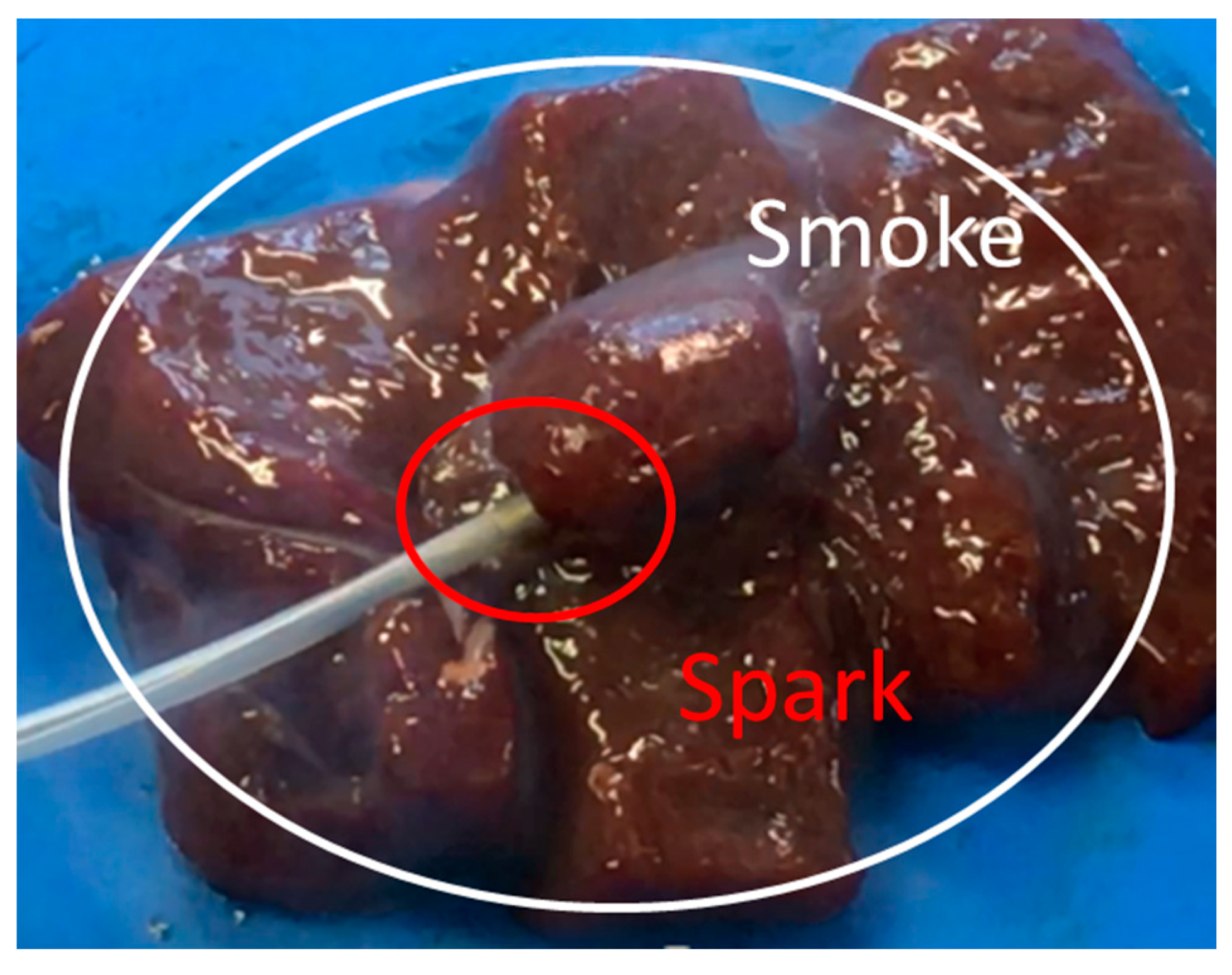
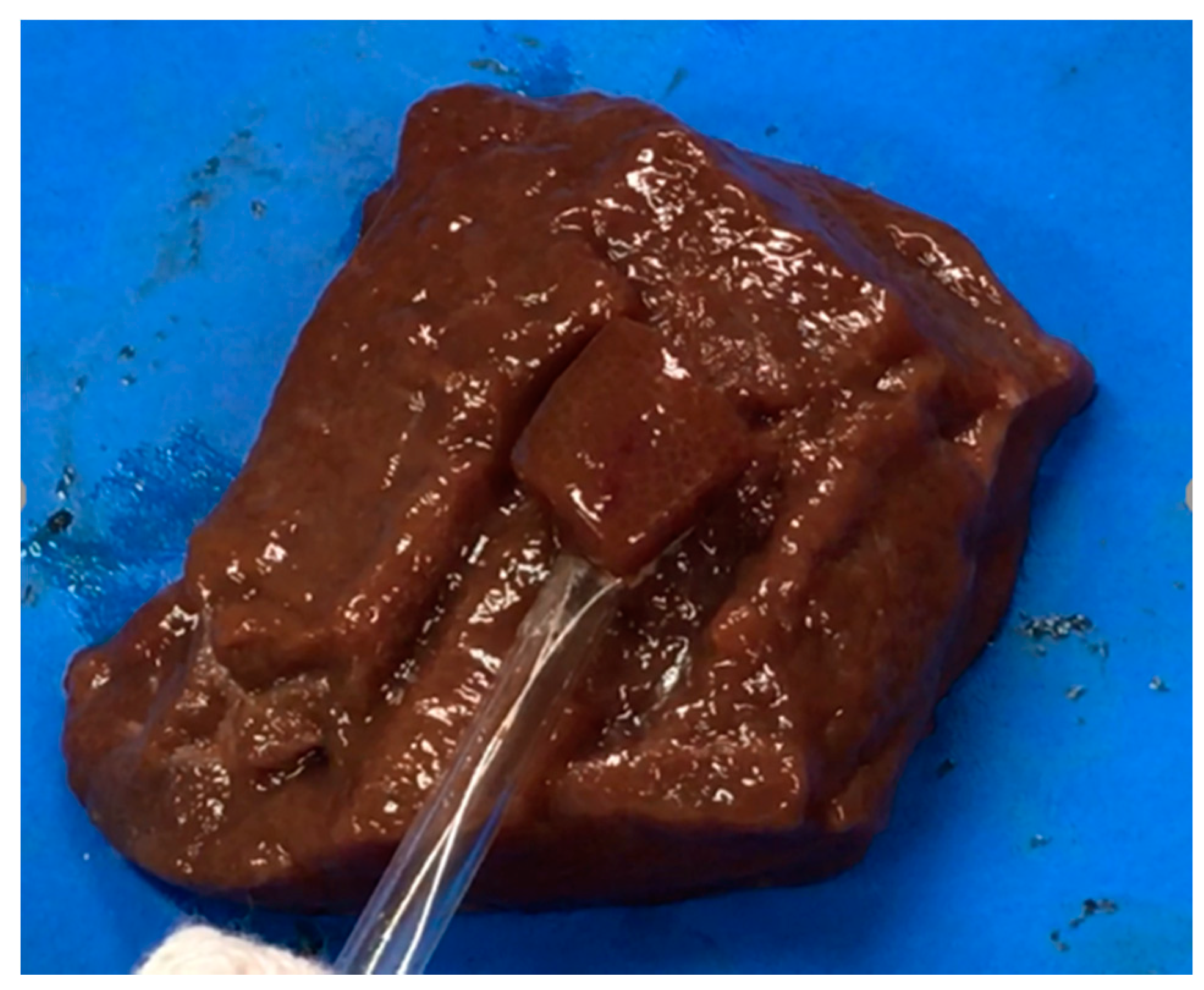
3.2. Experimental Validation
4. Discussion
Author Contributions
Funding
Acknowledgments
Conflicts of Interest
References
- Converse, M.; Bond, E.J.; Hagness, S.C.; Van Veen, B.D. Ultrawide band microwave space-time beam-forming for hyperthermia treatment of brest cancer. IEEE Trans. Microwave Theory Tech. 2004, 52, 1876–1889. [Google Scholar] [CrossRef]
- Seki, T.; Wakabayashi, M.; Nakagawa, T.; Itoh, T.; Shiro, T.; Kunieda, K.; Sato, M.; Uchiyama, S.; Inoue, K. Ultrasonically guided percutaneous microwave coagulation therapy for small carcinoma. Cancer 1995, 74, 817–825. [Google Scholar] [CrossRef]
- Liang, P.; Dong, B.; Yu, X.; Chang, Z.; Su, L.; Peng, J.; Nan, Q.; Wang, H. Computer-aided dynamic simulation of microwave-induced thermal distribution in coagulation of liver cancer. IEEE Trans. Biomed. Eng. 2001, 48, 821–829. [Google Scholar] [CrossRef] [PubMed]
- Nevels, R.D.; Arndt, G.D.; Raffoul, G.W.; Carl, J.R.; Pacifico, A. Microwave catheter design. IEEE Trans. Biomed. Eng. 1998, 45, 885–890. [Google Scholar] [CrossRef] [PubMed]
- Soetikno, R.M.; Gotoda, T.; Nakanishi, Y.; Soehendra, N. Endoscopic mucosal resection. Gastrointest. Endosc. 2003, 57, 567–579. [Google Scholar] [CrossRef] [PubMed]
- Ahlenstiel, G.; Hourigan, L.F.; Brown, G.; Zanati, S.; Williams, S.J.; Singh, R.; Moss, A.; Sonson, R.; Bourke, M.J.; The Australian Colonic Endoscopic Mucosal Resection (ACE) Study Group. Actual endoscopic versus predicted surgical mortality for treatment of advanced mucosal neoplasia of the colon. Gastrointest. Endosc. 2014, 80, 668–676. [Google Scholar] [CrossRef] [PubMed]
- Heresbach, D.; Kornhauser, R.; Seyrig, J.A.; Coumaros, D.; Claviere, C.; Bury, A.; Cottereau, J.; Canard, J.M.; Chaussade, S.; Baudet, A.; et al. A national survey of endoscopic mucosal resection for superficial gastrointestinal neoplasia. Endoscopy 2010, 42, 806–813. [Google Scholar] [CrossRef] [PubMed]
- Ahmad, N.A.; Kockman, M.L.; Long, W.B.; Fruth, E.E.; Ginsberg, G.G. Efficacy, safety, and clinical outcomes of endoscopic mucosal resection: A. study of 101 cases. Gastrointest. Endosc. 2002, 57, 567–579. [Google Scholar] [CrossRef] [PubMed]
- Yee, K.S. Numerical Solution of Initial Boundary Value Problems Involving Maxwell’s Equations in Isotropic Media. IEEE Trans. Antennas Propagat. 1966, 14, 302–307. [Google Scholar]
- Pennes, H.H. Physical properties of Tissue. J. Appl. Physiol. 1948, 1, 93–122. [Google Scholar] [CrossRef] [PubMed]
- IT’IS Foundation. Available online: https://itis.swiss/news-events/news/latest-news/ (accessed on 31 October 2018).


| Parameters | Microwave Snare | High Frequency Snare |
|---|---|---|
| Calculation method | FDTD | FEM |
| Power (W) | 60 | 30 |
| Heating time (s) | 10 | 3 |
| Electrical Constants | Frequency | Stomach |
|---|---|---|
| Relative permittivity | 500 kHz | 2060 |
| 2.45 GHz | 43.0 | |
| Conductivity (S/m) | 500 kHz | 0.55 |
| 2.45 GHz | 1.69 |
| Thermal Constants | Objects | Values |
|---|---|---|
| Specific heat (J/kg/K) | Stomach | 3690 |
| Fluororesin | 1000 | |
| Blood | 3960 | |
| Thermal conductivity (W/m/K) | Stomach | 0.53 |
| Fluororesin | 0.23 | |
| Density (kg/m3) | Stomach | 1088 |
| Fluororesin | 2200 | |
| Blood | 1050 | |
| Blood flow rate (m3/kg/s) | Stomach | 1.43 × 10⁻⁵ |
| Sizes | A (mm) | B (mm) |
|---|---|---|
| 1/2λ | 15 | 23 |
| 3/8λ | 11 | 15 |
| 1/4λ | 8 | 13 |
© 2018 by the authors. Licensee MDPI, Basel, Switzerland. This article is an open access article distributed under the terms and conditions of the Creative Commons Attribution (CC BY) license (http://creativecommons.org/licenses/by/4.0/).
Share and Cite
Sugiyama, M.; Saito, K. Characteristics of a Surgical Snare Using Microwave Energy. Diagnostics 2018, 8, 83. https://doi.org/10.3390/diagnostics8040083
Sugiyama M, Saito K. Characteristics of a Surgical Snare Using Microwave Energy. Diagnostics. 2018; 8(4):83. https://doi.org/10.3390/diagnostics8040083
Chicago/Turabian StyleSugiyama, Masashi, and Kazuyuki Saito. 2018. "Characteristics of a Surgical Snare Using Microwave Energy" Diagnostics 8, no. 4: 83. https://doi.org/10.3390/diagnostics8040083
APA StyleSugiyama, M., & Saito, K. (2018). Characteristics of a Surgical Snare Using Microwave Energy. Diagnostics, 8(4), 83. https://doi.org/10.3390/diagnostics8040083