Abstract
The development of an automatic walking-type pepper transplanter could be effective in improving the mechanization rate in pepper cultivation, where the dibbling mechanism plays a vital role and determines planting performance and efficiency. The objective of this research was to determine a suitable working speed for a gear-driven dibbling mechanism appropriate for a pepper transplanter, while considering agronomic transplanting requirements. The proposed dibbling mechanism consisted of two dibbling hoppers that simultaneously collected free-falling seedlings from the supply mechanism and dibbled them into soil. To enable the smooth collection and plantation of pepper seedlings, analysis was carried out via a mathematical working trajectory model of the dibbling mechanism, virtual prototype simulation, and validation tests, using a physical prototype. In the mathematical model analysis and simulation, a 300 mm/s forward speed of the transplanter and a 60 rpm rotational speed of the dibbling mechanism were preferable in terms of seedling uprightness and low mulch film damage. During the field test, transplanting was conducted at a 40 mm planting depth, using different forward speed levels. Seedlings were freely supplied to the hopper from a distance of 80 mm, and the success rate for deposition was 96.79%. A forward speed of 300 mm/s with transplanting speed of 120 seedlings/min was preferable in terms of achieving a high degree of seedling uprightness (90 ± 3.26), a low rate of misplanting (8.19%), a low damage area on mulch film (2341.95 ± 2.89 mm2), high uniformity of planting depth (39.74 ± 0.48 mm), and low power consumption (40.91 ± 0.97 W).
1. Introduction
Transplanting and harvesting operations are most in demand during the cultivation process of pepper (Capsicum annuum L.), and they need to be mechanized for optimal efficiency [1]. In the cultivation of pepper, like in other vegetables, manual transplanting is the most time-consuming and labor-demanding task [2]. Manual transplanting requires about 40% of the total operational time with 184 person-hours/ha needed for cultivation, and the results are often a nonuniform spatial distribution of crops [3,4,5]. Additionally, labor shortages in the peak season cause delays in transplanting operations, resulting in seedling mortality and, eventually, yield loss [6,7]. Therefore, with the except of some leading pepper cultivation countries, the cultivation area and production amount have been decreasing every year for pepper [8,9], even though the consumption rate per capita has been increasing [10,11]. To meet the ever-growing global demand for pepper, the total production rate needs to be rapidly increased. An increased level of mechanization in the pepper transplantation process could help to accelerate the global production rate.
An automatic transplanter can greatly facilitate upland farming with increased productivity. Many researchers have shown a keen interest in the development of a variety of mechanical transplanters by considering the dibbling operation of seedlings [12,13]. The dibbling mechanism is a major consideration for the development of a fully automatic transplanter. Many dibbling mechanisms, such as pockets, vertical descending cups, or buckets, split cone cups, and transplanting discs [14,15,16,17], have been developed with a bar link and cam mechanism, and have also been successfully implemented in the field. In terms of minimal seedling damage, cup-, bucket-, or hopper-type mechanisms have been found to be fairly efficient. For this reason, gear trains, instead of a bar link, have been used in the dibbling mechanisms [17]. Researchers have also focused on increasing the working speed of the dibbling mechanism, considering agronomic requirements for transplanting (i.e., straight upright orientation, certain planting depth, and less mechanical damage). Based on the literature, the acceptable range of straight upright orientation of the transplanted seedlings is 90 ± 20° [18,19]. Other agronomic requirements, such as planting depth, planting interval, and soil moisture content, also need to be maintained as 40–50 mm, 30–50 mm, and 15–25%, respectively, to operate the transplanter at 150–350 mm/s forward speeds [19,20,21,22,23,24]. Following on from these researchers, this study analyzes the gear-driven hopper-type dibbling mechanism of an automatic pepper transplanter with an improved design for efficiently planting seedlings at high speeds.
The forward speed of an automatic pepper transplanter needs to be synchronized with seedling pick-up, supply, and dibbling to achieve the desired planting interval and depth [25,26,27]. Hence, it is necessary to first determine a suitable working speed for the dibbling mechanism after considering the seedling pick-up and supply rates. Another important aspect is to determine a suitable working speed for the dibbling mechanism to plant seedlings with a satisfactory degree of uprightness and minimal physical damage to the seedlings, which are the key factors affecting plant growth and yield [28,29].
In transplanting operations, plastic mulch film is most often used to increase the survival rate of seedlings by protecting them from extreme weather [30]. Moreover, the mulch film helps in weed suppression and heat and moisture retention, resulting in better yield [5,31,32] For these reasons, transplanting operations are performed with care to maintain minimal mulch film damage, which depends on the speed of the dibbling mechanism. Thus, the design and development of any automatic or semiautomatic mechanical transplanter will almost certainly consider the optimal working speed of the dibbling mechanism [28,30,33].
The aim of this study was to determine a suitable working speed of a hopper-type dibbling mechanism of a walking-type pepper transplanter, in terms of the collection of the seedlings from the supply mechanism, planting them with minimal disturbance, and minimal mulch film damage, while considering agronomic requirements.
2. Materials and Methods
2.1. Working Principle of the Dibbling Mechanism
Pepper transplanting operations are generally performed in soil ridges, followed by covering with an impermeable plastic mulch film (40 mm thickness) [34]. Pepper seedlings are transplanted either in a single- or double-row pattern in a ridge. A double-row planting pattern for peppers is becoming popular because it requires less labor and plastic film. The width of the ridge with a double row is 1800 mm, and the height varies from 100 to 450 mm. The ridge-to-ridge distance is 1500 mm, and the row-to-row distance in the same ridge is 400 mm, where the planting interval generally remains at 150 mm [35]. Seedlings are grown in a tray; after 45 days, they are transplanted into the mulched ridge [36]. Seedlings grown in a tray are generally of one or two types: plug or paper-pot seedlings. Whether cylindrical paper-pot seedlings (40 mm diameter and 40 mm height) are more sustainable compared to plug seedlings for a transplanting depth similar to pot height has been investigated [36,37]. Table 1 shows the variable notations, definitions, and measurement units used in the analysis.

Table 1.
Variable notations, definitions, and measurement units.
In this study, an automatic walking-type pepper transplanter (Figure 1) under development was considered for the mechanization of transplanting in an existing two-row cultivation pattern. In the design of the transplanter, two dibbling-mechanism units (Figure 1d) were used to deposit paper-pot seedlings into the planting hole, linked with the seedling supplier and conveying unit. The dibbling mechanism uses a chopstick-type gripper and a conveying unit to continuously supply seedlings at a specified rate. During the operational period, chopstick-type grippers (Figure 1a) grasp a group of five plugs at a time from the plastic tray (500 × 285 mm) and transfer them to the release tray (Figure 1b). In the meantime, a push-bar assembly pushes the seedlings to the conveying unit (Figure 1c). The unit conveys the plug with an intermittent start-and-stop motion on the basis of the demand of the dibbling mechanisms. When the conveying unit stops, two seedlings freely fall, and the dibbling mechanisms collect them. After the seedlings are collected, they are deposited into the soil. A compacting part (Figure 1f) was used in this transplanter to push down the soil near the seedlings.
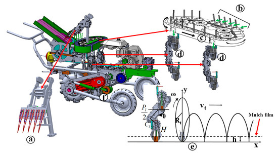
Figure 1.
Structure of the pepper transplanter under development: (a) seedling picking manipulator, (b) seedling supply, (c) conveying unit, (d) dibbling mechanism, (e) mathematical model of dibbling operations, and (f) soil-compacting device.
The dibbling mechanism for the two-row pepper transplanter designed in this study consisted of two dibbling hoppers continuously moving up and down, due to rotation of the mechanism. When the dibbling hopper goes into the top-up position, it collects a pepper seedling that has freely fallen from the supply unit. The hopper deposits the collected seedling inside the soil when it reaches the maximal down position. Here, a cam mechanism was used to open and close the hoppers of the mechanism to release the seedlings into the soil. A finger-type device is attached to the hopper to guide the seedlings to remain in a straight upright orientation from collection to planting. For every single rotation of the dibbling mechanism, two seedlings are collected and planted inside the soil. As seedlings freely fall into the dibbling mechanism, the seedlings’ physical properties were considered when selecting the rotating speed of the mechanism and seedling falling height.
2.2. Theoretical Analysis
2.2.1. Rotating Speed Selection of Dibbling Mechanism
For the design of the dibbling mechanism, it is important to first establish the rotating and forward speeds. Many walking-type transplanters that have been designed by researchers consider a forward speed of 245–390 mm/s [38,39]. In Korea, a walking-type Chinese cabbage transplanter was designed with a forward speed of 300 mm/s [17]. Following previous research, the forward speed of the transplanter was considered in the range of 250–350 mm/s, with analysis applied to determine the optimal speed. The rotational speed of the dibbling mechanism is dependent on the required planting interval and forward speed of the planter. Considering the forward speed range and the existing planting pattern, the rotating speed of the dibbling mechanism is calculated using Equation (1).
The planting supply rate to the mechanism can be determined using Equation (2), as suggested by Srivastava et al. [40].
Another important consideration for transplanting operations is that seedlings should be placed in the hopper in a straight and vertical orientation. The successful deposition of seedlings into the hopper depends on the required seedling supply rate, free-falling time, and falling distance. All of these factors must be synchronized with the rotating speed of the hopper to ensure the smooth deposition of seedlings into the hopper during operation. Seedlings should be deposited into the hopper when it goes into the top vertical point. For this reason, falling time in this case should be related to the horizontal velocity of the dibbling hopper. The falling time of the seedlings also has to be synchronized with the rotating speed of the dibbling mechanism and the seedling supply rate and manner. Seedling falling time can be determined using Equation (3), as the seedling supply system is involved in determining the rotational speed (n) of the planting mechanism.
The velocity of the free-falling pepper seedling is subject to aerodynamic drag, and depends on the physical properties of the seedlings; it can be expressed by Equations (4) and (5) [14].
Pepper seedlings that were 45 days old were suggested to be best suited for mechanical transplanting operations [36,37,41].
2.2.2. Constant Horizontal Speed of Seedling Deposition
Constant horizontal velocity should occur at the maximal lower point of the hopper working trajectory, where pepper seedlings are deposited inside the soil; this phenomenon is called zero-speed delivery. If this velocity of the dibbling hopper matches the forward speed of the transplanter, a seedling is released into the soil surface at the desired depth, which is crucial for this kind of transplanting [14]. In the maximal lower point of the hopper trajectory, there is no acceleration, such that the dibbling hopper can deposit the seedlings into the soil at the time of withdrawal from the soil. The constant horizontal velocity of seedling deposition should be equal but opposite to the forward velocity of the transplanter. The relation between forward velocity vt of the transplanter and horizontal velocity vx of the hopper should follow Equation (6).
To evaluate the zero-speed delivery of seedlings during transplanting operations, the working trajectory of the mechanism could provide a better overview. For developing the dibbling trajectory (Figure 1e), a mathematical model was derived on the basis of a Cartesian coordinate system. The forward speed of the transplanter was considered as the negative direction of the x-axis, and the vertical direction (upward to the soil) was considered as the positive direction of the y-axis. The lowest point of the dibbling trajectory was set in the original point. Further, the lowest point of the dibbling hopper was considered as the reference point; these phenomena can be described mathematically using Equation (7).
where rotational radius Rt of the dibbling hopper trajectory can be found using Equation (8).
2.2.3. Evaluation of Mulch Film Damage
During the manual transplanting process, farmers dig a hole, transplant a seedling, cover the hole, and move forward, and this process is repeated. In this way, seedlings are subjected to minimal stress and minimal damage is caused to the mulch film. For mechanical transplanting operations, the minimization of stress and mulch film damage should also be considered. Generally, the transplanting operation comprises two motions: first, the alternating motion in the vertical direction for drilling the holes; and second, the horizontal movement for moving forward. During mechanical transplanting in mulch film, the operation should ideally be executed as it would be by a human, without extra stress to the seedlings or any mulch film damage (Figure 2). Transplanting efficiency is not satisfactory because of the frequent starting and braking of the operation during transplanting. However, the gear-driven dibbling mechanism of a transplanter follows a trajectory during operation, where the part inside the film is close to a straight line and perpendicular to the soil surface. This is a continuous process, and provides both planting efficiency and no extra damage to the mulch film (Figure 1e). The trajectory (Figure 1e) specifies that the hopper of the dibbling mechanism should operate with a round-trip rectilinear motion within a short duration, confirming high acceleration. The high acceleration of the dibbling hopper imposes a substantial burden to the transplanter and possibly impacts seedlings during operation. To reduce acceleration, the restraints on the dibbling hopper motion are relaxed.
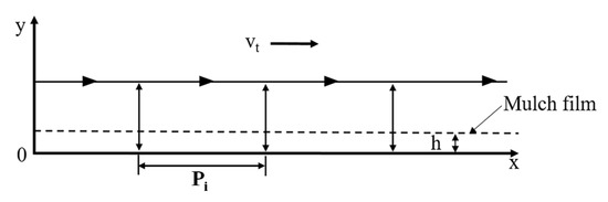
Figure 2.
Ideal transplanting operations in plastic film ridge with minimal mulch film damage, where h is the dibbling depth and Pi is the plant-to-plant distance after the transplanting operations.
Damage in the plastic film can be divided into two parts: on-film damage (w1) and beneath-film damage (w2) (Figure 3). Both parts contribute to the whole amount of damage, but the larger part causes more damage. On this basis, the larger part is responsible for almost the entirety of the damage. Hence, minimal damage occurs while both parts are the same and minimal in size. For determining the values of w1 and w2, the value of y was assumed to be zero. Then, from Equation (7), the required time (t) before reaching the dibbling hopper in the final point of the hole can be expressed by Equation (9).
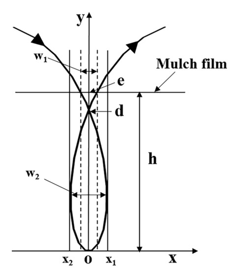
Figure 3.
Schematic representation of the working path of the hopper and resulting mulch film damage.
Half of the mulch film damage can be calculated using Equation (10).
where
considering that w1 = 2|x1| is true for the motion trajectory. Further, to determine the value of w2, the ratio of the derived values for x and y with respect to t was considered to be zero, which yielded Equation (12).
Putting the value of vt in Equation (7) gives . Hence, the value of x2 can be expressed by Equation (13).
The combination of x1 and x2 denotes the total mulch film damage, and the amount of x1 and x2 is the same but in the opposite direction.
The value of w2 = 2|x2|. Minimal plastic mulch damage occurs when w1 and w2 are the same. Hence, this equation is better for defining minimum mulch film damage because it offers an analytical relationship between vt, Rt, and ω [38].
2.3. Simulation and Validation
2.3.1. Motion Simulation
The planting trajectories were determined for different transplanting speeds, as illustrated in Figure 4, where different degrees of mulch film damage related to different trajectories are shown. The trajectories can be expressed on the basis of the characteristic coefficient (λ), which is the ratio of the circumferential speed of the dibbling mechanism and the transplanter forward speed [27]. Figure 4 shows that when the λ increases, the mulch film damage first decreases to a minimum and then increases again. Hence, mulch film damage is minimal at λ = 1. When the value of λ exceeds 1, mulch film damage also consistently increases. For both λ < 1 and λ > 1, on- and beneath-film damage was significant. However, for λ = 1, on- and beneath-film damage was the same, which was considered to be the minimal mulch film damage condition. It was important to determine the working speed to satisfy the required value of the characteristic coefficient.
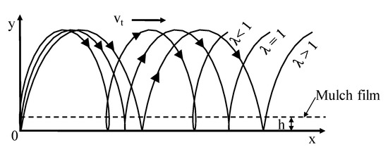
Figure 4.
Possible trajectory of the dibbling hopper during transplanting operations in a mulch film ridge for different forward speeds of the transplanter.
To derive the optimal working speed of the dibbling mechanism, a design and motion study was performed using a mechanical design and simulation software package (SolidWorks Simulation-2017, Dassault Systèmes SolidWorks Corp., Massachusetts, USA). A virtual prototype was designed and operated at different forward speeds in the range of comfortable human walking speed. The trajectories for different transplanter forward speeds were determined and analyzed to determine the speed corresponding to minimal mulch film damage. The rotational speed of the dibbling mechanism was determined to be in a range of 40 to 80 rpm on the basis of the planting interval and a suitable free-falling seedling height. The forward speed of the transplanter was considered to be in a range of 250–350 mm/s.
2.3.2. Validation Tests with Prototype
To evaluate the derived results from the simulation, a prototype of the dibbling mechanism was fabricated and operated using a test bench with a 30 × 30 mm aluminum profile. Four U-grooved wheels (bore diameter: 30 mm; outer diameter: 38 mm) were attached to the base of the test bench for free horizontal movement. A 1200 W three-phase electric motor and chain-sprocket mechanism were used for moving the test bench at the desired forward and backward speeds on parallel steel-pipe rails (Figure 5). Another set of parallel steel-pipes were used as a base of the rails. The diameter of the pipes were 35 mm and the distance between them was 900 mm. The height of the parallel pipes from the ground was 600 mm, which was adjusted for achieving the required planting depth. The required power for operating the dibbling mechanism was provided by another 1500 W three-phase electric motor with controlled rotational speeds. The speeds of the electric motors were controlled (0 to 60 Hz) using two separate inverters (SV-iG5A; LS Industrial Systems Co., Anyang, Republic of Korea). To determine the power requirements of the dibbling operation, a torque sensor (TRS605; FUTEK Co., CA, USA) was installed in the power-transmission line between the motor and dibbling mechanism. The torque sensor provided a 99.8% measurement accuracy during the operation. A data-acquisition device (NI 6212; National Instruments, Austin, TA, USA) was used to acquire signals from the sensor. A software program was developed for torque sensor data acquisition. Data from the torque sensor were smoothed using a 20-point symmetric moving average method [42].
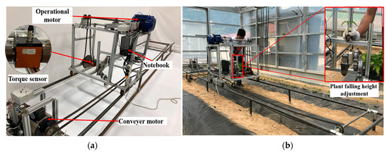
Figure 5.
Test bench for pepper transplantation using the dibbling mechanism (a), and field experiment photo (b).
Mulch film damage and the misplanting rate (i.e., the wrong position or the angle between the stem and ground is below 30° [18]) were evaluated for the dibbling mechanism, where pepper seedlings were planted at forward speeds of 250, 300, and 350 mm/s with a 60-rpm rotational speed of the dibbling mechanism (Figure 5). The 45-day-old pepper seedlings were manually dropped into the hopper from a certain height, and the seedling deposition rate in the dibbling hopper was noted. The transplanting operation was conducted five times in three mulched ridges (5000 × 350 × 150 mm). Mulch film damage, the misplanting rate, planting depth uniformity, and planting interval uniformity were evaluated during the experiment. Mulch film damage and planting depth uniformity were measured using Vernier calipers, and plant uprightness was measured using a protractor. All measurements were taken with five replications to achieve the accurate readings. The experiment was conducted inside a plastic greenhouse (36.367° N, 127.344° E) of the research field of Chungnam National University, Republic of Korea. The soil of the experimental site was sandy loam comprising 70% sand, 12% silt, and 18% clay [43]. Other soil properties were also measured with five replications, such as the Cone Index up to 150 mm using a handheld cone penetrometer (Penetrologger 6.00, Eijkelkamp, Giesbeek, The Netherlands), and soil water content, soil temperature, and soil electrical conductivity (EC) using a soil sensor (WT 1000N, RF sensor, Seoul, Korea). The measurement error of the penetrometer was less than 1%, and were ±1%, ±0.1 dS/m, and ±0.5 °C for soil water content, EC, and soil, respectively. The major properties of the soil in the experimental site are presented in Table 2.
Table 2.
Major soil properties of experimental field.
3. Results and Discussion
3.1. Rotational Mechanism Speed
The rotating speed of the dibbling mechanism depends on the forward speed of the planter and the desired planting interval. Considering a comfortable walking speed range of 250–350 mm/s and a 150 mm planting interval for pepper transplanting, the required rotating speeds of the planting mechanism ranged from 50 to 80 rpm, as shown in Figure 6. For 45-day-old pepper seedlings with heights of 230 ± 20 mm and masses of 43.45 ± 5 g (including both plant and soil), the successful deposition of seedlings into hoppers was considered. A greater falling height of the seedlings is subject to greater air drag, so there is a chance for inappropriately dropping the seedling in the hopper. Minimal clearance is also required between the seedling release point and the hopper working path. Under these conditions, the free-falling distance of the seedling was considered to be 80 mm. The rotating speed of the dibbling hopper was then calculated to be 60 rpm, as illustrated in Figure 6. In the validation tests, the success rate for seedling deposition in the hopper was 96.79% for a free-falling height of 80 mm. During the experiment, seedlings observed to contain more leaves were thereby subjected to more air drag. The inappropriate placement rate for the straight-shaped and less-leafed seedlings was insignificant. Machine vibration could also be a notable reason for the displacement of seedlings during free falling. However, the success rate of seedling deposition in the hopper might be increased if the transplanting operation is conducted using uniformly shaped seedlings and maintaining minimal machine vibration.
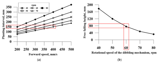
Figure 6.
The relation between the planting interval and the rotational speed of the dibbling mechanism for different forward speeds (a), and seedling free-falling height, according to the rotational speed of the dibbling mechanism (b).
For the desired planting depth of 40 mm, transplanter forward speeds of 250 and 350 mm/s provided planting depths of 37.68 ± 1.87 and 34.82 ± 2.17 mm, respectively (Figure 7). For the same desired planting depth, a 300 mm/s forward speed provided planting depths of 39.74 ± 0.48 mm. From the experiment, it was observed that a transplanter forward speed of 300 mm/s resulted in better planting depth uniformity than compared with forward speeds of 250 and 350 mm/s. Theoretically, this mechanism releases the seedlings in the lowest position of its working trajectory because of the difference in the horizontal speed of the hopper and the transplanting forward speed; significant depth variations were observed for 250 and 350 mm/s (Figure 7). If the seedlings are released before or after the hopper reaches to the lowest down position in terms of the working trajectory, greater nonuniformity in planting depths could occur. During 250 and 350 mm/s forward speed conditions, this phenomenon might occur.
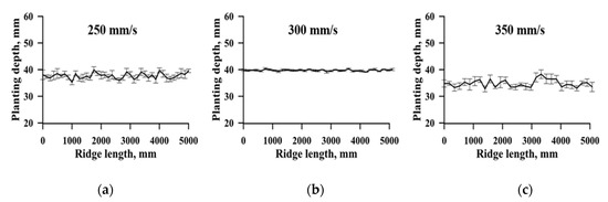
Figure 7.
Planting depth uniformity during transplanting operations for transplanter forward speed levels of 250 (a), 300 (b), and 350 mm/s (c).
3.2. Seedling Deposition with Constant Horizontal Speeds
The characteristic coefficient was considered for three different cases, namely λ > 1, λ = 1, and 0 < λ < 1 for transplanter forward speeds of 250, 300, and 350 mm/s, respectively. The trajectories of the dibbling mechanism for these cases are shown in Figure 8. At a transplanter forward speed of 250 mm/s, the characteristic coefficients were greater than 1. In this case, the trajectory of the dibbling mechanism formed a cycloid under the soil surface, and there was an inflection point at the lowest position of the cycloid (Figure 8). The direction of the horizontal speed on the cycloid was the same as the direction of the transplanter forward speed except for the inflection point. The speed at the inflection point could meet the requirements for constant horizontal speed. However, seedlings were bumped forward because the inflection point located at the lowest position of the working trajectory and the cycloid immediately moved forward after delivering the seedlings at the inflection point. On the other hand, the seedlings had a certain height, and it took a short time for the delivered seedlings to escape from the developed cycloid inside the soil. This indicates that the seedlings where the cycloid was sequentially moving forward did not completely escape from the cycloid that had formed under the soil. This may cause harm to the seedlings and even possibly break down the seedling stems. Furthermore, when the dibbling mechanism made a hole for seedling deposition into the soil, it went into one point and came out from another point of the surface, which caused uncertain mulch film damage. Thus, λ > 1 was not favorable for delivering the pepper seedlings using the dibbling mechanism.
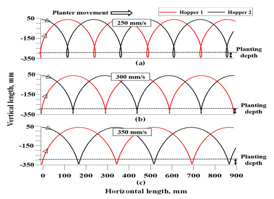
Figure 8.
Trajectory of dibbling hopper for forward speeds of 250 (a), 300 (b), and 350 mm/s (c).
A tangent point on the working trajectory of the dibbling mechanism was able to indicate the direction for the ultimate speed of seedling movement. For the transplanter forward speed of 350 mm/s, 0 < λ < 1 was yielded in the working trajectory of the dibbling mechanism, where a portion of the working trajectory under the soil surface generated a very short cycloid (Figure 8). The direction of the horizontal speed at every point of the short cycloid was the same as the direction of the forward speed of the transplanter. This indicates that, in this case, the horizontal forward speed direction of the transplanter and the inclination of the delivered pepper seedlings were severe because the dibbling mechanism did not have enough time for seedling deposition and to move out from the soil. As a result, the seedlings were not able to escape from the hopper for straight upright orientation. Thus, constant horizontal speed delivery was not obtained in this case. In addition, extra mulch film damage resulted for different entry and exit points of the dibbling mechanism.
Under the condition of λ = 1 (at a 300 mm/s transplanter forward speed), the trajectory under the soil was almost a straight line, which indicated that the hopper went inside the soil at a certain point, deposited the seedling, and came out from the same point. These phenomena happened because the speed of the dibbling hopper at the seedling deposition point was equal and opposite to the forward speed of the transplanter. Therefore, in this case, the seedlings were delivered at a constant horizontal speed, as shown in Figure 8, and the required degree of uprightness for the seedlings was also possible. Moreover, the cycloid movement could keep the seedlings in an upright orientation. In the field test, maximum uprightness of the planted seedlings was also found in this condition (Figure 9). As the dibbling mechanism entered and exited from the same point, mulch film damage was minimal. Thus, the value of the characteristic coefficient being equal to 1 was an essential condition for normal transplanting operations using the machine.
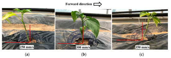
Figure 9.
Uprightness of pepper seedlings after transplantation at different forward speed levels of transplanting operations of 250 (a), 300 (b), and 350 mm/s (c).
From these results, it can be stated that, to plant seedlings with straight upright orientation, it is essential to maintain a 1:1 ratio of the circumferential speed of the dibbling mechanism and the transplanter forward speed during the operation. By maintaining this ratio, it would possible to minimize mechanical damage to the seedlings similarly to manual operation.
3.3. Mulch Film Damage and Power Consumption
Theoretically, minimal mulch film damage was calculated for a transplanter forward speed of 300 mm/s. During the field test, the lengths of torn plastic film in the planting hole for speeds of 250, 300, and 350 mm/s were 64.3 ± 1.91, 54.3 ± 1.91, and 65.7 ± 1.8 mm, respectively. The corresponding widths were 52.4 ± 1.6, 43.13 ± 1.51, and 54.1 ± 1.48 mm, respectively (Figure 10). Mulch film damage was minimal for a 300 mm/s forward speed. Maximal mulch film damage occurred at 350 mm/s forward speed because the dibbling hopper would drag forward, generating force horizontal to the film along with the forward direction of the transplanting operation. The transplanter forward speed of 300 mm/s satisfied λ = 1, where the dibbling hopper entered the soil to deliver the seedlings and exited from the same point. On the other hand, for the 250 and 350 mm/s transplanter forward speeds, the hopper entered at one point and exited from another, as previously discussed. This is why the transplanter forward speed of 300 mm/s resulted in minimal damage to the mulch film compared to the other speeds. Therefore, in order to maintain minimal mulch-film damage during operations using this mechanism, it is important to maintain the condition where λ = 1.
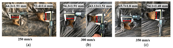
Figure 10.
Mulch film damage during 250 (a), 300 (b), and 350 mm/s (c) forward speeds of transplanting operations.
Transplantation was operated using the dibbling mechanism at three different forward speeds (i.e., 350, 300, and 250 mm/s), and power consumption was measured for all speeds. The measured power consumption data of the dibbling mechanism showed continuous reciprocating curves during the transplanting operation (Figure 11). The minimal power consumption value was recorded at a 0.25 s interval because both of the dibbling hoppers remained in the air in this position. The dibbling hoppers simultaneously contacted the soil for depositing the seedlings at 0.5 s intervals. For this reason, the power consumption value of the dibbling mechanism reached the maximum at a 0.5 s interval. Points A and B (Figure 11) indicate the soil interaction with dibbling hoppers 1 and 2, respectively. For the three different tested forward speeds, the power consumption of the dibbling mechanism was recorded as 48.09 ± 1.42, 40.91 ± 0.97, and 49.9 ± 1.29 W, respectively. Comparatively low power consumption was observed for a 300 mm/s forward speed because, in this condition, the forward speed was neutralized in the dibbling point by the developed horizontal speed of the dibbling hopper. Hence, no external force of the forward speed acted on the dibbling hopper during seedling delivery. For transplanter forward speeds of 350 and 250 mm/s, the dibbling hoppers were dragged in backward and forward directions, respectively. While the hoppers touched the soil for seedling delivery, the stress on the hopper varied for the different forward speed conditions. For a 250 mm/s forward speed, the hopper produced a cycloid inside the soil that forced the hopper to dig a hole with comparatively larger area, consuming greater power. For a 350 mm/s forward speed, the hopper also produced a hole with a larger area, but while it dragged forward, a portion of the forward speed helped to reduce power consumption. This was the reason that the power consumption of the dibbling mechanism at a 350 mm/s forward speed was a little lower than that at a 250 mm/s forward speed.
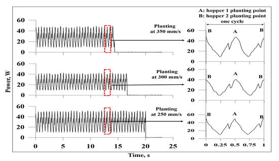
Figure 11.
Power consumption of the dibbling mechanism during transplanting operations at different forward speeds.
For the 300 mm/s forward speed, when the dibbling hopper entered and exited from the same point, a hole with a comparatively minimal area was produced; for this reason, power consumption was relatively greater for both of the other speed conditions. Test results with the dibbling mechanism at 250, 300, and 350 mm/s forward speeds and 60 rpm rotational speed are presented in Table 3. In comparing the theoretical and measured values at three different forward speeds for a 60 rpm rotational speed of the dibbling mechanism, the 300 mm/s forward speed provided better performance. The seedling upright angle was observed as 90° ± 3.26°, with a success rate of 91.8% for the 300 mm/s forward speed. Various researchers evaluated different dibbling mechanisms by performing transplanting operations with 150 to 200 mm/s forward speeds, where the soil water content was considered in a range from 15 to 25% and found the success rate of transplanting as 91–93% [21,24]. Based on the field experiments, the success rate of transplanting using the proposed dibbling mechanism was similar, although the transplanter forward speed was higher than the previous research results. The data of the power consumption experiment showed that minimal power consumption for the dibbling mechanism was obtained when λ = 1.
Table 3.
Results of field experiments for different forward speed levels of transplanting operations.
4. Conclusions
In this study, the working speed of a gear-driven dibbling mechanism for an automatic pepper transplanter was analyzed, considering three main aspects (i.e., appropriate deposition of free-fallen seedlings into the dibbling mechanism from the conveying mechanism, successful deposition of seedlings inside the soil with straight upright orientation, and minimal damage to the mulch film). According to the suggested planting interval for pepper transplantation, the ideal rotational speed was found to be 60 rpm for the dibbling mechanism, with a planting frequency of 2 seedlings/s per row. The free-falling height of the pepper seedlings was determined as 80 mm for appropriate dropping into the hopper. By deriving the working trajectory, it was confirmed that for a transplanter forward speed of 300 mm/s, the dibbling mechanism could plant the seedlings in a straight upright orientation with minimal disturbance and comparatively low mulch film damage. To evaluate the theoretical findings, a test bench was fabricated for operation of a physical prototype. In the field tests, seedling uprightness, the misplanting rate, mulch film damage, and power requirements were also measured for different working speeds. By comparing the results of the theoretical analysis, simulation, and field tests, it can be certified that the results from this study are identical. As a consequence, the field experiment revealed that the gear-driven hopper-type dibbling mechanism showed good feasibility for transplanting pepper seedlings into the mulch film ridge when a 1:1 ratio of the circumferential speed of the dibbling mechanism to the transplanter forward speed was maintained. According to the field tests, preferable seedling uprightness was found for only one condition (i.e., a 300 mm/s forward speed, and a 150 mm planting interval). Therefore, there is a scope to improve this mechanism by making it favorable for different speeds and planting intervals. Furthermore, it would be supportive to achieve more accurate results by considering the transvers and longitudinal inclination of the field. The outcomes of this study might be helpful to accelerate the mechanization process for seedling transplanting operations.
Author Contributions
Conceptualization, S.-O.C. and M.Z.I.; methodology, S.-O.C.; software, M.Z.I.; validation, M.Z.I., S.-O.C., Y.-J.K., and T.P.; formal analysis, M.Z.I., M.N.I., and S.I.; investigation, S.-O.C., T.P., and M.C.; resources, S.-O.C.; data curation, M.Z.I., M.N.I., and S.I.; writing—original draft preparation, M.Z.I.; writing—review and editing, S.-O.C., Y.-J.K., T.P., and M.C.; visualization, M.Z.I. and M.N.I.; supervision, S.-O.C.; project administration, S.-O.C.; funding acquisition, S.-O.C. All authors have read and agreed to the published version of the manuscript.
Funding
This work was supported by the Korea Institute of Planning and Evaluation for Technology in Food, Agriculture, Forestry, and Fisheries (IPET) through the Advanced Production Technology Development Program, funded by the Ministry of Agriculture, Food, and Rural Affairs (MAFRA) (project no. 317013-03), Republic of Korea.
Institutional Review Board Statement
Not applicable.
Informed Consent Statement
Not applicable.
Data Availability Statement
The data presented in this study are available within the article.
Conflicts of Interest
The authors declare no conflict of interest.
References
- Choi, Y.; Jun, H.J.; Lee, C.K.; Lee, C.S.; Yoo, S.N.; Suh, S.R.; Choi, Y.S. Development of a mechanical harvesting system for red pepper(i)—Surveys on conventional pepper cultivation and mechanization of pepper harvesting. J. Biosyst. Eng. 2010, 35, 367–372. [Google Scholar] [CrossRef][Green Version]
- Zamani, D. Development and evaluation of a vegetable transplanter. Int. J. Eng. Res. Appl. 2014, 2, 40–46. [Google Scholar]
- Tsuga, K. Development of fully automatic vegetable transplanter. Japan Agric. Res. Q. 2000, 34, 21–28. [Google Scholar]
- Kumar, G.V.P.; Raheman, H. Vegetable transplanters for use in developing countries—A review. Int. J. Veg. Sci. 2008, 14, 232–255. [Google Scholar] [CrossRef]
- Parish, R.L. Current developments in seeders and transplanters for vegetable crops. Horttechnology 2005, 15, 46–51. [Google Scholar] [CrossRef]
- Chowdhury, M.; Islam, M.N.; Iqbal, M.Z.; Islam, S.; Lee, D.H.; Kim, D.G.; Jun, H.J.; Chung, S.O. Analysis of overturning and vibration during field operation of a tractor-mounted 4-row radish collector toward ensuring user safety. Machines 2020, 8, 77. [Google Scholar] [CrossRef]
- Khadatkar, A.; Mathur, S.M.; Gaikwad, B.B. Automation in transplanting: A smart way of vegetable cultivation. Curr. Sci. 2018, 115, 84–92. [Google Scholar] [CrossRef]
- FAO (Food and Agriculture Organization of the United Nations). 2018. Available online: http://www.fao.org/faostat/en/#data/QC (accessed on 27 November 2020).
- Statistics Korea. 2018. Available online: http://kostat.go.kr/portal/eng/index.action (accessed on 27 November 2020).
- Nam, J.S.; Byun, J.H.; Kim, T.H.; Kim, M.H.; Kim, D.C. Measurement of mechanical and physical properties of pepper for particle behavior analysis. J. Biosyst. Eng. 2018, 43, 73–84. [Google Scholar]
- Kang, T.S. Identification of undeclared ingredients in red pepper products sold on the South Korea commercial market using real-time PCR methods. Food Control 2018, 90, 73–80. [Google Scholar] [CrossRef]
- Nandede, B.M.; Raheman, H. A tractor drawn vegetable transplanter for handling paper pot seedlings. AMA Agric. Mech. Asia Africa Lat. Am. 2016, 47, 87–92. [Google Scholar]
- Sun, J.F.; Li, X.Y.; Li, W.J.; Zhu, Y.Z.; Wang, J.; Wang, Q. Structure design of manipulator for pot seedling transplanter and simulation analysis. In Applied Mechanics and Materials; Liu, H., Kuroda, S., Zheng, L., Eds.; Trans Tech Publications Ltd.: Stafa-Zurich, Switzerland, 2014; Volume 670–671, pp. 829–833. [Google Scholar]
- Manilla, R.D.; Shaw, L.N. A high-speed dibbling transplanter. Trans. ASAE 1987, 30, 0904–0908. [Google Scholar] [CrossRef]
- Herrison, R.D.; Herrison, P.B.; Zuhoski, J. Computer Operated Automatic Seedling Plant Transplanting Machine. U.S. Patent 4947579, 14 August 1990. [Google Scholar]
- Dong, F.; Geng, D.; Wang, Z.; Dong, F.; Geng, D.Y.; Wang, Z.Y. Study on block seedling transplanter with belt feeding mechanism. Trans. Chin. Soc. Agric. Mach. 2000, 31, 42–45. [Google Scholar]
- Park, S.H.; Cho, S.C.; Kim, J.Y.; Choi, D.K.; Kim, C.K.; Kwak, T.Y. Development of rotary type transplanting device for vegetable transplanter. J. Biosyst. Eng. 2005, 30, 135–140. [Google Scholar] [CrossRef]
- Han, L.H.; Mao, H.P.; Hu, J.P.; Kumi, F. Development of a riding-type fully automatic transplanter for vegetable plug seedlings. Spanish J. Agric. Res. 2019, 17, 0205. [Google Scholar] [CrossRef]
- Xue, X.; Li, L.; Xu, C.; Li, E.; Wang, Y. Optimized design and experiment of a fully automated potted cotton seedling transplanting mechanism. Int. J. Agric. Biol. Eng. 2020, 13, 111–117. [Google Scholar] [CrossRef]
- Ji, J.; Cheng, Q.; Jin, X.; Zhang, Z.; Xie, X.; Li, M. Design and test of 2ZLX-2 transplanting machine for oil peony. Int. J. Agric. Biol. Eng. 2020, 13, 61–69. [Google Scholar]
- Jin, X.; Cheng, Q.; Zhao, B.; Ji, J.; Li, M. Design and test of 2ZYM-2 potted vegetable seedlings transplanting machine. Int. J. Agric. Biol. Eng. 2020, 13, 101–110. [Google Scholar] [CrossRef]
- Yin, D.Q.; Wang, J.Z.; Zhang, S.; Zhang, N.Y.; Zhou, M.L. Optimized design and experiments of a rotary-extensive-type flowerpot seedling transplanting mechanism. Int. J. Agric. Biol. Eng. 2019, 12, 45–50. [Google Scholar] [CrossRef]
- Liu, J.; Zhao, S.; Li, N.; Faheem, M.; Zhou, T.; Cai, W.; Zhao, M.; Zhu, X.; Li, P. Development and Field Test of an Autonomous Strawberry Plug Seeding Transplanter for Use in Elevated Cultivation. Appl. Eng. Agric. 2019, 35, 1067–1078. [Google Scholar] [CrossRef]
- Zhou, M.; Shan, Y.; Xue, X.; Yin, D. Theoretical analysis and development of a mechanism with punching device for transplanting potted vegetable seedlings. Int. J. Agric. Biol. Eng. 2020, 13, 85–92. [Google Scholar]
- Islam, M.N.; Iqbal, M.Z.; Ali, M.; Chowdhury, M.; Kabir, M.S.N.; Park, T.; Kim, Y.J.; Chung, S.O. Kinematic analysis of a clamp-type picking device for an automatic pepper transplanter. Agriculture 2020, 10, 627. [Google Scholar] [CrossRef]
- Jin, X.; Li, D.; Ma, H.; Ji, J.; Zhao, K.; Pang, J. Development of single row automatic transplanting device for potted vegetable seedlings. Int. J. Agric. Biol. Eng. 2018, 11, 67–75. [Google Scholar] [CrossRef]
- Ye, B.; Zeng, G.; Deng, B.; Yang, C.; Liu, J.; Yu, G. Design and tests of a rotary plug seedling pick-up mechanism for vegetable automatic transplanter. Int. J. Agric. Biol. Eng. 2020, 13, 70–78. [Google Scholar] [CrossRef]
- Ji, J.T.; He, Y.K.; Du, X.W.; He, Z.T.; Du, M.M.; Zheng, Z.H.; Jia, S.T.; Liu, J.J.; Liu, Q. Design of the up-film transplanter and kinematic analysis of its planting devices. In Proceedings of the International Conference on Advanced Mechatronic Systems, Luoyang, China, 25–27 September 2013; ICAMechS (IEEE): New York, NY, USA, 2013. [Google Scholar]
- Manes, G.; Anoop, D.; Arsdeep, S.; Mahal, J. Feasibility of mechanical transplanter for paddy transplanting in Punjab. AMA Agric. Mech. Asia Africa Lat. Am. 2013, 44, 4–7. [Google Scholar]
- Jiaodi, L.; Weibin, C.; Dongyang, T.; Haiyang, T.; Hongzheng, Z. Kinematic analysis and experiment of planetary five-bar planting mechanism for zero-speed transplanting on mulch film. Int. J. Agric. Biol. Eng. 2016, 9, 84–91. [Google Scholar]
- Chen, Z.; Sun, S.; Zhu, Z.; Jiang, H.; Zhang, X. Assessing the effects of plant density and plastic film mulch on maize evaporation and transpiration using dual crop coefficient approach. Agric. Water Manag. 2019, 225, 105765. [Google Scholar] [CrossRef]
- Zhang, X.; Yang, L.; Xue, X.; Kamran, M.; Ahmad, I.; Dong, Z.; Liu, T.; Jia, Z.; Zhang, P.; Han, Q. Plastic film mulching stimulates soil wet–dry alternation and stomatal behavior to improve maize yield and resource use efficiency in a semi-arid region. F. Crop. Res. 2019, 233, 101–113. [Google Scholar] [CrossRef]
- Jun, F.; Gui, Q.; Weitang, S.; Yajia, L. The kinematic analysis and design criteria of the dibble-type transplanters. Trans. Chin. Soc. 2002, 33, 48–50. [Google Scholar]
- Kim, G.W.; Das, S.; Hwang, H.Y.; Kim, P.J. Nitrous oxide emissions from soils amended by cover-crops and under plastic film mulching: Fluxes, emission factors and yield-scaled emissions. Atmos. Environ. 2017, 152, 377–388. [Google Scholar] [CrossRef]
- RDA. Rural Development Administration. Information about Pepper Farming Process. 2014. Available online: https://www.krei.re.kr/DATA/portlet-repositories/agri/files/1500615806032.pdf (accessed on 27 November 2020).
- Dihingia, P.C.; Prasanna Kumar, G.V.; Sarma, P.K. Development of a hopper-type planting device for a walk-behind hand-tractor-powered vegetable transplanter. J. Biosyst. Eng. 2016, 41, 21–33. [Google Scholar] [CrossRef]
- Kim, H.C.; Cho, Y.H.; Ku, Y.G.; Bae, J.H. Seedling qualities of hot pepper according to seedling growth periods and growth and yield after planting. Korean J. Hortic. Sci. Technol. 2015, 33, 839–844. [Google Scholar] [CrossRef]
- Du, S.; Yu, J.; Wang, W. Determining the minimal mulch film damage caused by the up-film transplanter. Adv. Mech. Eng. 2018, 10, 168781401876677. [Google Scholar] [CrossRef]
- Kumar, G.V.P.; Raheman, H. Development of a walk-behind type hand tractor powered vegetable transplanter for paper pot seedlings. Biosyst. Eng. 2011, 110, 189–197. [Google Scholar] [CrossRef]
- Ajit, K.S.; Carroll, E.G.; Roger, P.R.; Dennis, R.B. Engineering Principles of Agricultural Machines, 2nd ed.; American Society of Agricultural and Biological Engineers: St. Joseph, MI, USA, 2006. [Google Scholar]
- Seo, T.C.; An, S.W.; Kim, S.M.; Nam, C.W.; Chun, H.; Kim, Y.C.; Kang, T.K.; Woo, S.K.; Jeon, S.G.; Jang, K.S. Effect of the seedlings difference in cylindrical paper pot trays on initial root growth and yield of pepper. Prot. Hortic. Plant Fact. 2017, 26, 368–377. [Google Scholar] [CrossRef]
- Rohrer, R.A.; Luck, J.D.; Pitla, S.K.; Hoy, R. Evaluation of the accuracy of machine reported can data for engine torque and speed. Trans. ASAE 2018, 61, 1547–1557. [Google Scholar] [CrossRef]
- Oh, T.K.; Lee, J.H.; Kim, S.H.; Lee, H.C. Effect of biochar application on growth of Chinese cabbage (Brassica chinensis). Korean J. Agric. Sci. 2017, 44, 359–365. [Google Scholar]
Publisher’s Note: MDPI stays neutral with regard to jurisdictional claims in published maps and institutional affiliations. |
© 2021 by the authors. Licensee MDPI, Basel, Switzerland. This article is an open access article distributed under the terms and conditions of the Creative Commons Attribution (CC BY) license (http://creativecommons.org/licenses/by/4.0/).