1. Introduction
Compliant mechanism has been a popular device in precision systems due to the highly repeatable motions generated by elastic deformation of thin flexures. In addition, the backlash-free, friction-free, and maintenance-free allow compliant mechanisms to operate more reliably and accurately than traditional rigid mechanisms in micro/nano positioning/alignment systems [
1].
Compliant mechanisms can be synthesized based on both serial and parallel configurations. In precision engineering, compliant parallel mechanism (CPM) is preferred because of the insensitivity to external disturbances, high payload, and good dynamic performance [
2,
3]. To satisfy various requirements of precise positioning/alignment systems, CPMs are required to produce a variety of output motions. Based on previous literatures, a vast number of multiple degrees-of-freedom (DOF) CPMs have been developed, ranging from 2-DOF to 6-DOF [
4,
5,
6,
7,
8,
9,
10,
11,
12,
13,
14,
15,
16,
17,
18,
19,
20,
21,
22,
23]. Among them, the three-legged configuration has been widely used in three-DOF in-plane-motion (X-Y-θ
Z) CPMs [
9,
10,
11,
12,
13] and three-DOF out-of-plane-motion (θ
X-θ
Y-Z) CPMs [
14,
15,
16,
17,
18] because it offers stable structure and performs lower actuating stiffness as compared to the four-legged counterpart, which is often used to design two-DOF planar-motion (X-Y) CPMs [
4,
5,
6]. Furthermore, the three-legged configuration has also been employed to create six-DOF CPM [
19,
20,
21,
22,
23], a complicated design due to the challenges in synthesizing six individual motions based on parallel spring-systems. For six-DOF positioning stages, the motion decoupling capability, demonstrated by the elimination of parasitic motions [
24], is always desired in order to produce highly accurate output motions. Referring to previous works [
19,
20,
21,
22,
23], the motion decoupling of CPMs has not been clearly discussed even though it is important. Another drawback that could limit the application range of existing six-DOF CPMs is the small workspace, i.e., <1 mm for translations and <1° for rotations. In addition, the dynamic behaviors, which are essential for precise motion systems, have not been considered so that existing designs are unable to achieve targeted dynamic responses.
This research work aims to overcome the drawbacks of existing six-DOF CPMs, by proposing a novel design with decoupled motions and a large workspace. In this work, the criteria for designing three-legged CPMs with fully-decoupled motions presented in [
25] are employed and integrated into the beam-based structural optimization method [
26] to synthesize a novel six-DOF CPM with both stiffness property and six primary resonance frequencies being optimized. Typically, dynamic property of a CPM is determined by the stiffness and the mass distribution within the entire structure. Since the stiffness of CPM is minimized to obtain the desired DOF, the better dynamic responses can be obtained by reducing some masses. Past literatures show that large-workspace CPMs in precision systems can obtain the highest first resonance frequency of ~100 Hz [
12,
16,
17]. Normally, almost mass distributes at the end effector and limits the dynamic performance of CPM. Thus, designing a lighter end-effector while maintaining stiffness is a potential solution to enhance the dynamic behaviors for CPMs. Because the size of the end effector is constrained, the mass of the end effector can only be significantly reduced if it is constructed by cellular/lattice structures. A prototype of the CPM with cellular end effector will be built by electron beam melting (EBM) method as this method has been demonstrated to be suitable to fabricate compliant devices [
16,
17]. The behaviors of the 3D-printed prototype will be experimentally evaluated in terms of stiffness/dynamic characteristics and motion decoupling capability.
The remaining of this paper is organized as follows:
Section 2 presents the synthesis of a novel six-DOF CPM with decoupled motions and optimized mechanical characteristics. The application of cellular structure to improve dynamic behavior of the synthesized CPM is mentioned in
Section 3.
Section 4 describes the experiments to evaluate the stiffness, dynamic and motion properties of the prototype. Finally, some conclusions are conducted in
Section 5.
2. Synthesis of the Six-DOF CPM
In this section, the criteria for designing 3-legged CPMs with fully-decoupled motions derived in [
25] are integrated into the beam-based structural optimization method presented in [
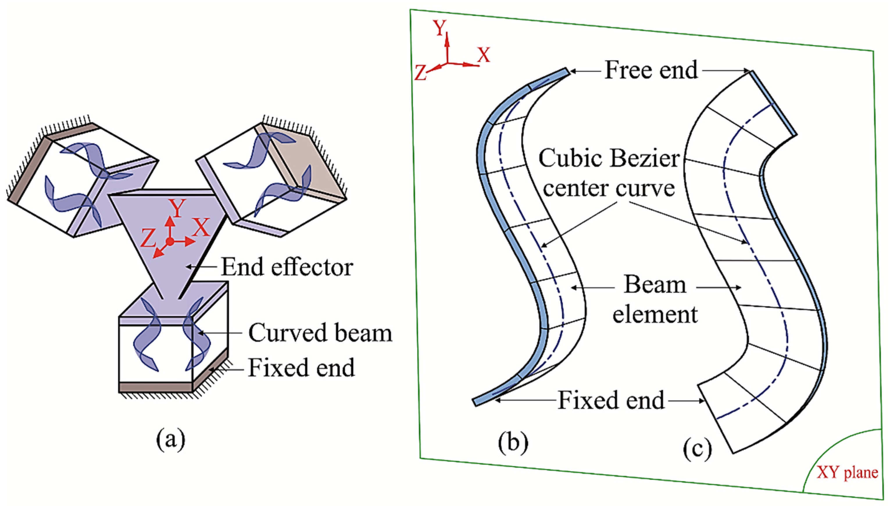
26] to synthesize a novel 6-DOF CPM. The general structure of a CPM created by the beam-based method is illustrated in
Figure 1a. The desired motions are generated by the elastic deformations of three symmetrical legs about the Z axis, each leg is constructed by a pair of specific beams with one end being fixed and another end being rigidly connected to the moving end-effector. Referring to the designing criteria in [
25], the motion decoupling capability can be achieved using the beam with zero twist angle. Hence, curved beams are directly used in this work to create the CPM with 6 DOF. The detailed modeling of these beams is described in [
26]. In particular, the center curves of the beams are defined in the XY plane and the orientation of the beam can only be 90° (perpendicular to the XY plane as shown in
Figure 1b) or 0° (parallel to the XY plane as shown in
Figure 1c) in order to obtain the decoupled output motions.
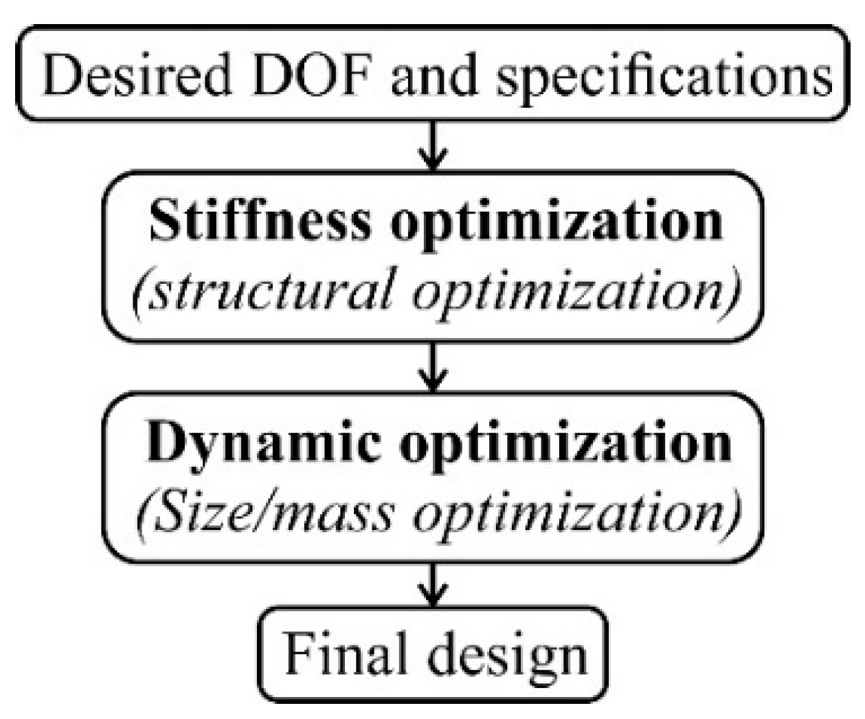
The optimization process of the beam-based method is shown in
Figure 2. The stiffness optimization is done first to find the optimal geometry of the curved beams and as a result, the CPM can produce 6 DOF at the end effector. The dynamic optimization is then carried out to determine the size of the curved beams as well as to distribute additional masses at suitable positions. Details of the stiffness and dynamic optimizations can be found in [
26].
By using beam-type flexures with the actuating stiffness being minimized, the 6-DOF CPM is desired to have large workspace. Furthermore, the first resonance frequency is targeted at 100 Hz and the differences between neighbor modes are required to be large to improve the dynamic behaviors. The design space of each leg shown in
Figure 1a is assigned as 50 × 50 mm
2. As mentioned above, the dimension along the Z axis is eliminated since the center curves of beams are located in the XY plane to ensure the motion decoupling capability of the entire CPM.
In order to generate 6 DOF at the end effector, geometry of the center curve that defines the curved beam is determined by the stiffness optimization process. The main purpose of this step is to minimize the six primary stiffness of the CPM. Referring to
Figure 1b, the CPM is constructed by a pair of curved beams in each compliant leg and each curved beam is created by a number of beam elements. Let
Ke and
Me be the [12 × 12] stiffness and mass matrices of each beam element respectively,
Ks and
Ms be the [
s ×
s] stiffness and mass matrices of the entire CPM respectively, the formulations of
Ks and
Ms are expressed as
where
N denotes the total number of beam elements in the CPM.
The [6 × 6] stiffness matrix,
K, represents the stiffness characteristics in the six DOF of the CPM can be obtained by the condensation of
Ks. Details of the matrix condensation are described in [
26].
The energy approach presented in [
26] is employed to formulate the objective function for the stiffness optimization. If
Ui is the displacement at the center of the end effector caused by the load
Pi (
i = 1, 2, …, 6 represent the six DOF Δ
X, Δ
Y, Δ
Z, θ
X, θ
Y, and θ
Z, respectively); the work,
Wi, done by
Pi can be addressed as
where
Kii denotes the
ith diagonal component in
K. As the beam-based optimization method is developed based on finite element method and the CPM is constructed by a number of beam elements, the expression of
Kii is in complicated numerical form with the design variables of the stiffness optimization included and not practical to be fully expressed here.
The CPM is able to obtain 6 DOF when the six corresponding works are maximized. To represent this requirement, the objective function is defined as
Under specific loads
Pi, κ is a constant factor and can be eliminated from the objective function. As a result, Equation (4) can be simplified as
Equation (5) is solved by the genetic algorithm (GA) solver in Matlab. During the stiffness optimization process, geometry of the curved beam changes after each iteration in order to minimize the stiffness property of the CPM. The process stops when the optimal values of
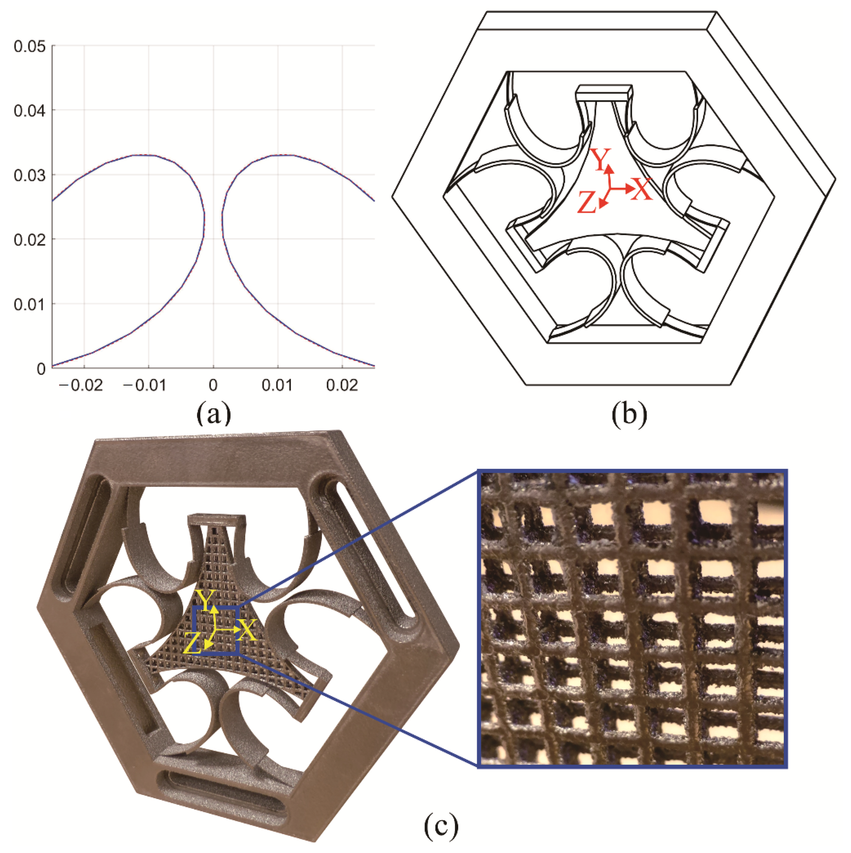
Kii that satisfy Equation (5) are obtained. The optimal geometry of two reflecting curved beams in a leg is illustrated in
Figure 3a. Note that the optimized orientation of the curved beams is 90°, which means that the beams are perpendicular to the XY plane as shown in
Figure 3b.
Next, the dynamic optimization process is carried out by determining the cross-sectional area of the curved beams, the size of the end effector as well as distributing additional masses at suitable positions. The detailed modeling of mass distribution along the curved beam is presented in [
26].
The dynamic property of the CPM can be expressed as
Here, ω and Fs are the bandwidth and natural frequency vectors of the CPM respectively; Fi, the ith component in Fs, represents the natural frequency of the ith vibration mode of the CPM.
The dynamic optimization can be done by solving the dynamic objective function represented by a set of two equations shown in Equation (7). The first equation is used to enhance the first resonance frequency,
F1, of the CPM to the desired value,
Fd = 100 Hz, and maximize the difference between two neighbor modes. In addition, the high flexibility of the entire CPM is maintained by the second equation.
The multi-objectives optimization using GA solver in Matlab is used to solve Equation (7). The structure of the entire CPM after the dynamic optimization process is shown in
Figure 3b with the optimized cross-section of the curved beams and the size of the end effector being determined. Moreover, an additional mass represented by a segment with bigger cross-sectional area is also added at the middle of each curved beam. In particular, the cross-sectional areas of the curved beams and the additional masses are 0.41 × 6.43 mm
2 and 1.20 × 12.44 mm
2, respectively, the size of the end effector is defined by the distance of 35.02 mm from its center to the moving end of each leg. Six primary resonance frequencies of the CPM, which are the first six components in
Fs, are represented by the frequency vector,
F. The stiffness characteristic of the CPM is represented by the compliance matrix,
C, which is the inverse of the stiffness matrix (
K). The obtained results of
C and
F are given in Equations (8) and (9), respectively.
Note that Ti6Al4V, a popular material for EBM process, is used to print the CPM. Ti6Al4V has Young’s modulus of 111 GPa, Poisson ratio of 0.34, density of 4.5 g/cm
3 and yield stress of 950 MPa. The obtained results can be verified by substituting the optimized geometrical parameters of the curved beams shown in
Figure 3a and the optimized values of design variables given above into the analytical approach of the beam-based method, which is presented in [
25].
In Equation (9), the first component of 100 Hz within
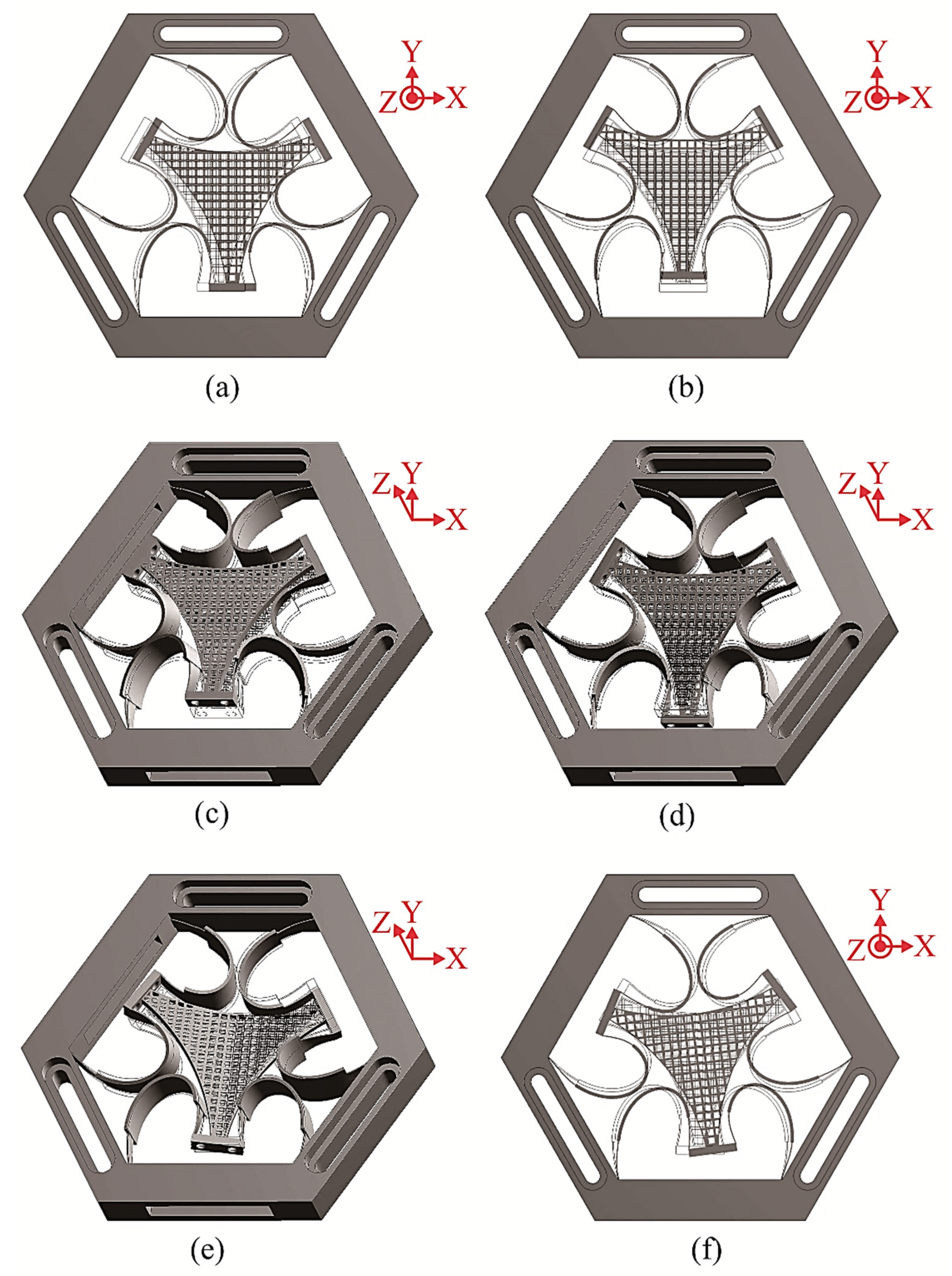
F is the resonance frequency of the translation along the Z axis, the second and third modes (148 Hz) are the translation along the X and Y axes, respectively, the resonance frequency of the rotation about the Z axis is 169 Hz and the last two modes shape (340 Hz) are the rotations about the X and Y axes. The elastic deformation of the CPM in each direction is demonstrated in
Figure 4. The simulation results via ANSYS show that the optimized CPM can produce a large workspace of ±3 mm × ±3 mm × ±6.5 mm × ±6° × ±6° × ±7.5°.
3. Improvement of Dynamic Property by Employing Cellular Structure
When designing a compliant mechanism for positioning systems, the dynamic response is desired to be as high as possible. Good dynamic response of any structure can be achieved with high stiffness and low mass. Due to the conflict between stiffness and dynamic properties, the first resonance frequency is targeted at 100 Hz to maintain the low actuating stiffness. Typically, the mass is lowered by reducing the volume of structure or using lighter materials. For CPM, the end effector is the only rigid part having significant mass and so it is chosen for reducing its mass to enhance the dynamic behaviors of the entire CPM. As the CPM will be 3D printed monolithically to eliminate assembly errors, the advantage of 3D printing technology in fabricating cellular/lattice structures [
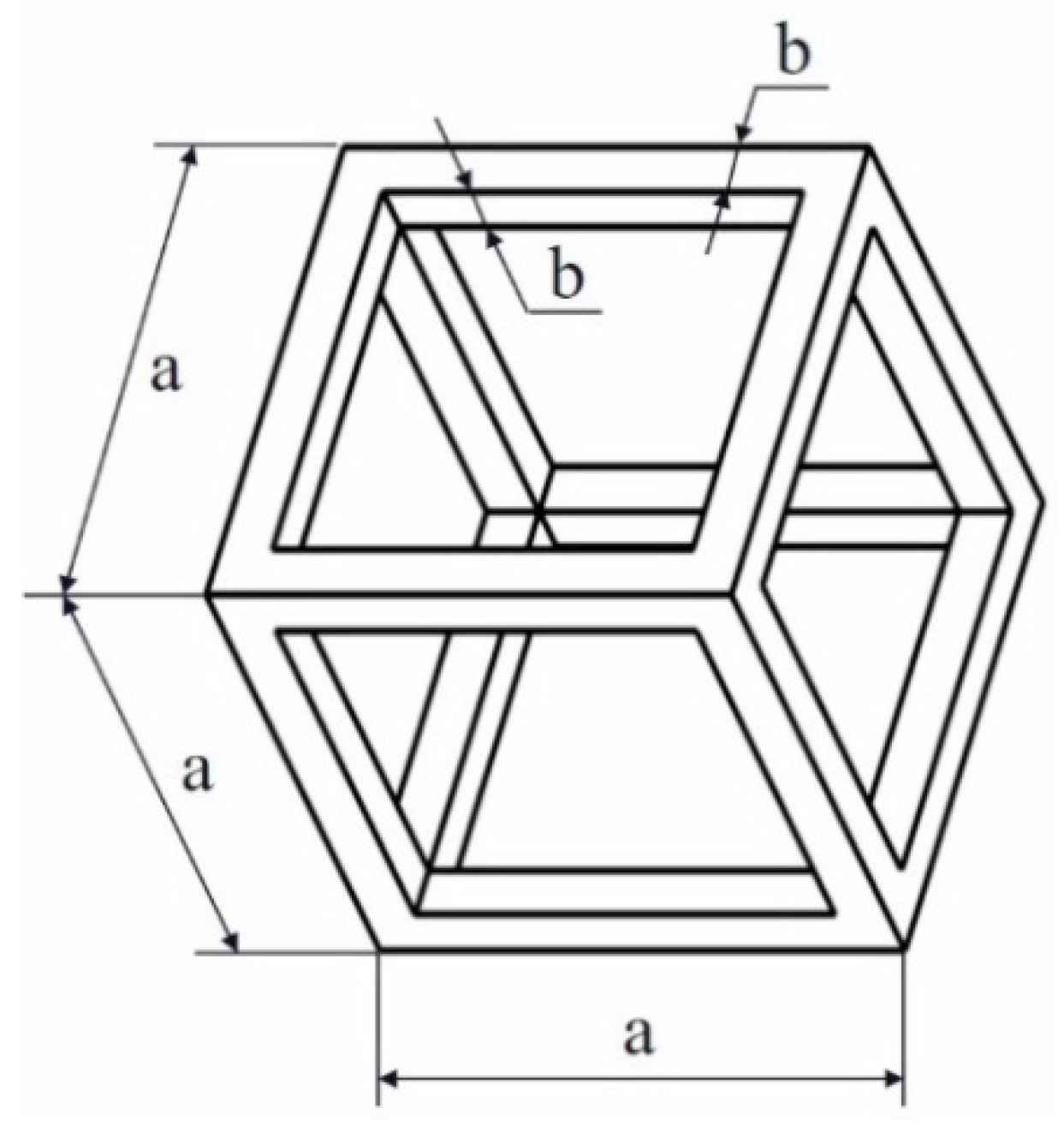
27] is exploited in this work to enhance the dynamic behavior of the CPM. In particular, a simple cellular structure illustrated in
Figure 5 is used to design the end effector to reduce its mass while its stiffness is maintained.
In
Figure 5, the cellular element is modeled by a hollow cube. It is created by a frame structure with the length and cross-sectional area of each beam being
a and
b2 respectively. Note that each beam has a square cross section. The relationship between
a and
b is given as
The volume of a cellular element as shown in
Figure 5,
Vcellular, is expressed as
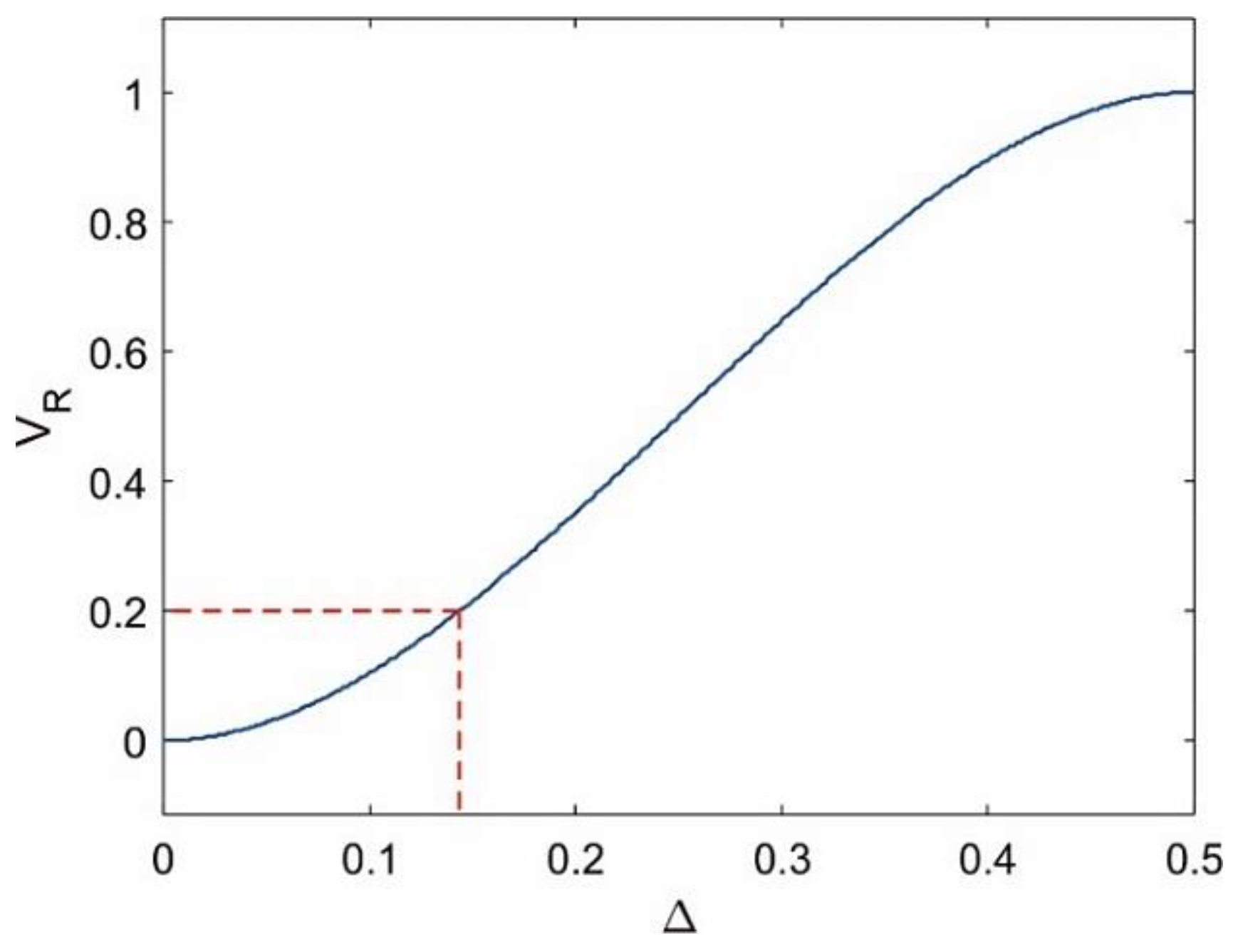
The volume ratio,
VR, representing the ratio between the volumes of cellular structure (
Vcellular) and solid structure (
Vsolid) is
Figure 6 illustrates the relationship between
VR and Δ. It is observed that the volume of cellular structure is equal to zero when Δ = 0 and equal to a solid structure when Δ = 0.5. This represents the CPM can achieve faster dynamic response with the smaller mass/volume of the end effector. However,
VR cannot be too small since it makes the cellular structure weaker and as a result, the end effector can be easily deformed and buckled under external loads. Many simulations have been done and the results suggest that
VR = 0.2 (corresponding to Δ = 0.144) is small enough to maintain the rigidity of the end effector and prevent the buckling failure while reducing its mass up to 80%. The CPM is reanalyzed with the cellular end-effector and the updated frequency vector,
Fcellular, is shown in Equation (13). Comparing Equation (13) to Equation (9), it is observed that the first resonance frequency has increased 33% and the total difference between neighbor modes is also improved.
Note that after applying the cellular structure to design the end effector, the order of six vibration modes is unchanged. In addition, the stiffness of the CPM is still represented by Equation (8) since the curved beams and the rigidity of the end effector are remained.
In summary, the application of cellular structure to improve the dynamic characteristics of CPMs has been demonstrated in this work. The obtained results show that the dynamic behavior of the CPM with cellular end effector is significantly better than the same counterpart with solid end effector. Together with the predictable mechanical properties of 3D-printed CPMs demonstrated in previous literatures [
16,
17,
25], the findings in this work on using cellular structures to enhance the dynamic characteristics of CPMs will be a useful reference for designers to further improve performances of compliant devices in precision motion systems.
4. Experimental Investigation and Results
A physical prototype of the synthesized CPM built by EBM technology with Ti6Al4V material is shown in
Figure 3c. It is observed that the end effector is constructed by cellular structure as illustrated in
Figure 5. Note that the building direction is along the Z axis of the prototype. As performance of EBM-printed CPM is determined by the effective thickness of flexures [
16], coefficient factors presented in [
28] have been used to compensate the difference between the designed and effective thicknesses of EBM-printed flexures. The effective thickness of an EBM-printed thin beam is determined by the product of the designed thickness and the corresponding coefficient factor. Referring to [
28], the coefficient factors for the thickness of the curved beam (0.41 mm) and the thickness of the additional mass (1.20 mm) are 1.29 and 0.88 respectively. After using these coefficient factors for compensating the thicknesses of the curved beams and the additional masses, the predicted stiffness and dynamic properties of the 3D-printed CPM are represented by
and
, respectively.
Note that and will be used to represent the stiffness and dynamic properties of the 3D-printed CPM in the remaining of the paper. After the thickness compensation, the workspace of ±3 mm × ±3 mm × ±6.5 mm × ±6° × ±6° × ±7.5° of the CPM is still maintained.
4.1. Evaluation of Stiffness Property
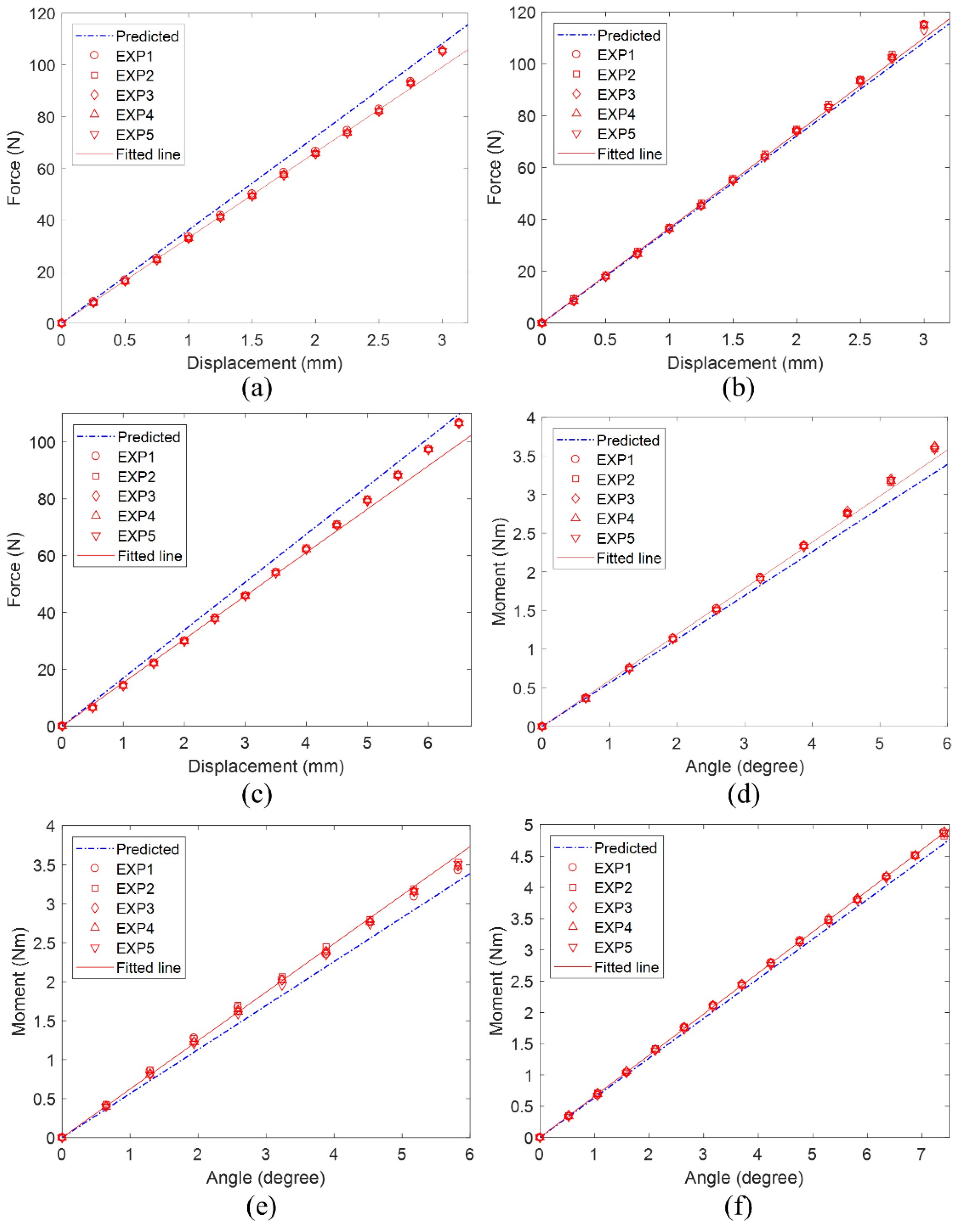
The stiffness property of the prototype is evaluated over the full workspace. Each experiment was measured at many positions and repeated five times to demonstrate the repeatability of the CPM. The experimental results were then compared to the predicted data in Equation (14).
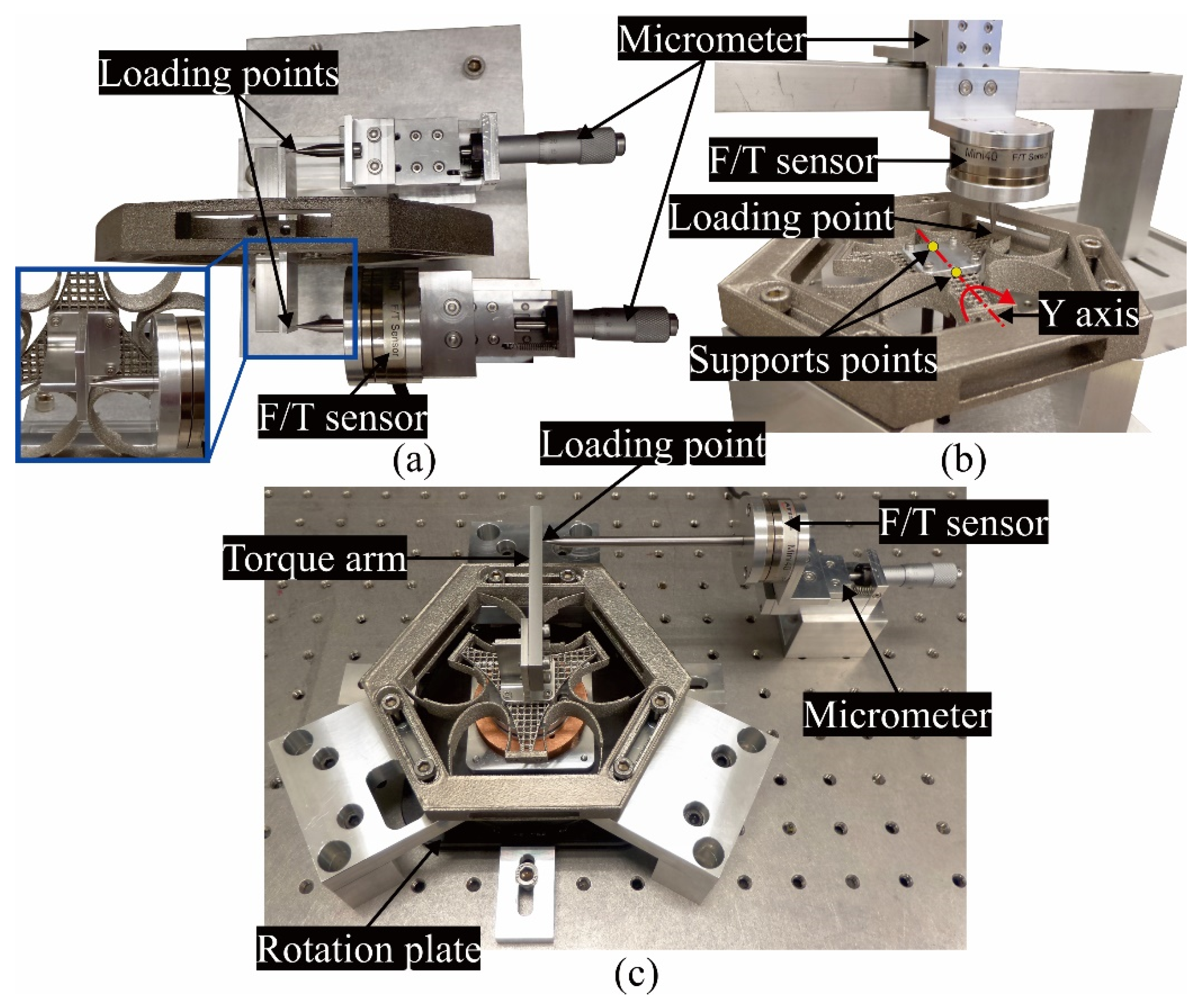
The experimental setup to evaluate the compliance along the X axis is shown in
Figure 7a. Two micrometers located at two opposite sides of the CPM were used to apply a pure force along the X axis to the end effector. A six-axes force/torque (F/T) sensor (ATI Mini40) was attached on one micrometer to measure the actuating force. Both micrometers were adjusted with the same displacement to ensure the end effector only displaced along the X axis. With this experimental setup, the reading from the F/T sensor indicated a haft of the total force applied to the CPM. A similar setup was adopted to measure the compliance along the Y axis. The experimental compliance along the X and Y axes are shown in
Figure 8a,b, respectively.
Figure 7b shows the experimental setup to measure the compliance about the Y axis of the CPM. Two contact points were installed at the bottom surface of the end effector, the input force along the Z direction from the micrometer was measured by the F/T sensor. The force was applied at a specific distance from the rotation axis, the bending moment and the rotation angle were calculated based on this distance and the corresponding input force. The similar setup was adopted to evaluate the compliance about the X axis. To measure the compliance along the Z axis, the support points were removed and the loading point was shifted to the center of the end effector. The experimental compliance along the Z axis, about the X and Y axes are shown in
Figure 8c–e, respectively.
To evaluate the compliance about the Z axis, a micrometer was used to apply the horizontal force to a torque arm rigidly mounted to the end effector as shown in
Figure 7c. A rotational plate was attached below the CPM to support its motion, only the rotation about the Z axis was allowed. Based on the force measured by the F/T sensor and the distance between the loading point and the rotation axis, the torque and rotation angle can be determined. The experimental result of the compliance about the Z axis is shown in
Figure 8f.
Referring to
Figure 8, it is seen that the CPM is able to perform good repeatability and the full workspace of ±3 mm × ±3 mm × ±6.5 mm × ±6° × ±6° × ±7.5° was experimentally achieved. The measured values, the predicted data and their deviations are summarized in
Table 1.
The data in
Table 1 demonstrates that the experimental stiffness characteristics of the prototype well agree with the predicted values with the highest deviation of ~10.5% over its large workspace. The deviations are mostly caused by fabrication errors, i.e., high surface roughness and lower accuracy as compared to traditional CNC machining processes. Based on the obtained results, it can be concluded that the synthesized CPM is able to produce large working range, repeatable motions, good and predictable stiffness property.
4.2. Evaluation of Decoupled Motions
Because the motion decoupling capability is an important characteristic of the synthesized six-DOF CPM, it is experimentally measured here. The direct way to verify decoupled-motion characteristic is to show that there is no parasitic motion generated when applying a specific actuating load in the desired direction and producing the required output motion. Due to the complexity in measuring both parasitic and desired motions simultaneously, the motion decoupling characteristic is verified by the energy approach. Through this approach, the desired motion in a specific direction is considered as decoupled when the energy caused by the actuating load and all undesired parasitic motions is zero. Energy of a motion generated by the CPM can be determined based on the actuating load and components in the stiffness matrix. Referring to [
25], the stiffness (or compliance) matrix of a general three-legged CPM has symmetrical form as shown in Equation (16). To evaluate the motion decoupling capability, five non-diagonal components, i.e.,
,
,
,
and
in the stiffness matrix (
) of the CPM must be experimentally measured to demonstrate that they are nearly equal to zero.
Assuming the non-diagonal components in
exist, the total energy (work done) in the
ith direction,
Wi, can be expressed as
In Equation (17),
Wi is the combination of the energy of desired motion (defined by
Pi and
) and the energies of undesired parasitic motions (defined by
Pi and
with j ≠ i). A motion can be considered as decoupled if the energies caused by parasitic motions have minor contributions over the total energy. Based on Equation (16), when applying a force along the X axis, two parasitic motions are generated, i.e., the rotations about the X and Y axes represented by
and
respectively. The bending moments about the X and Y axes were measured by the F/T sensor with the same setup as shown in
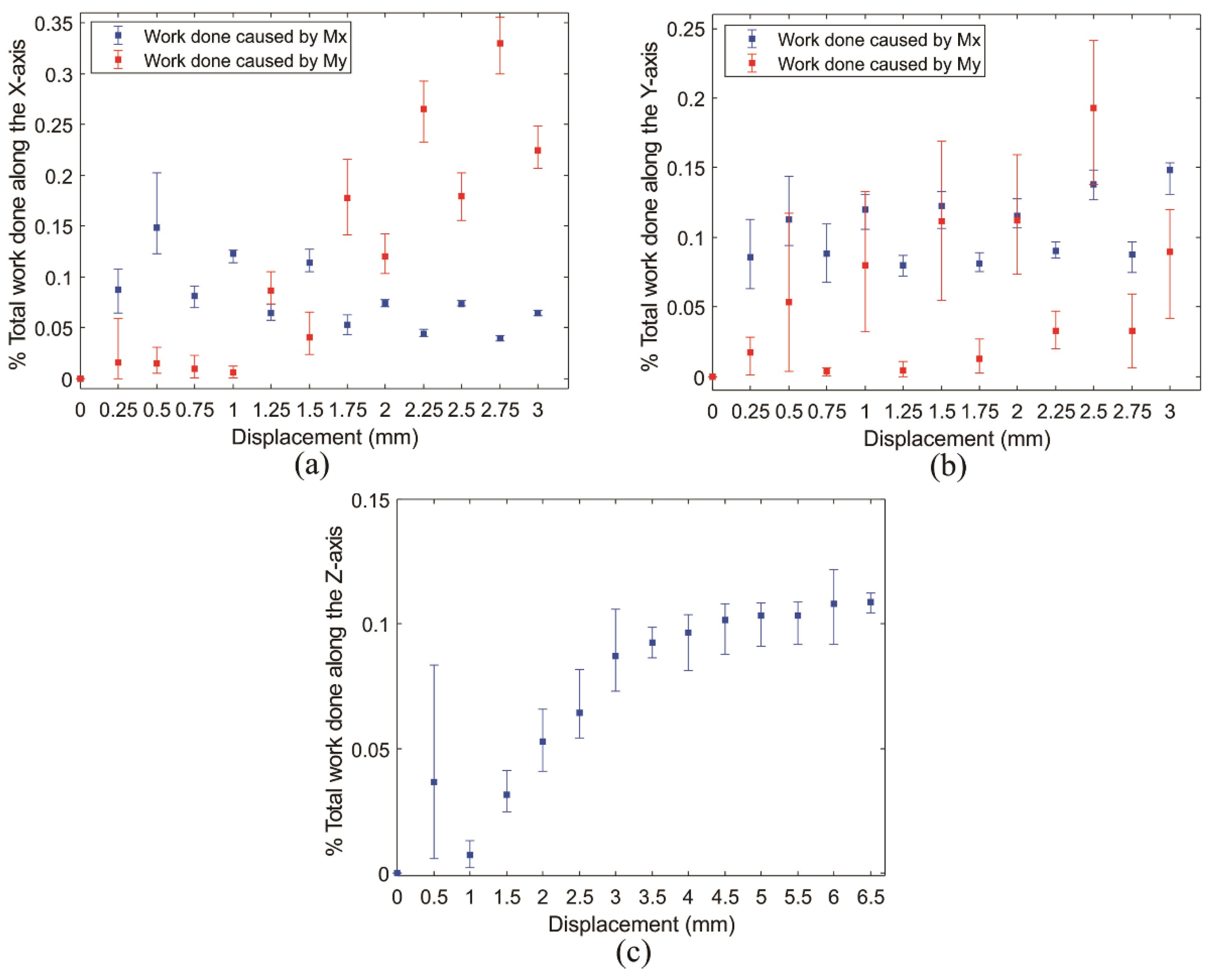
Figure 7a. The experiment was conducted five times and the graph shows the ratios between energies of parasitic motions and the total energy along the X axis is plotted in
Figure 9a. With similar experimental setups being adopted, the energy ratios along the Y and Z axes are illustrated in
Figure 9b,c, respectively.
Based on
Figure 9, the highest energies of parasitic motions only contribute about 0.35%, 0.2%, and 0.1% over the total energies along the X, Y, and Z axes, respectively. Those demonstrated that the parasitic motions are caused by the non-ideal experimental setups, i.e., the directions of input forces are not ideally parallel to the desired actuating directions. The obtained results suggested that almost input energy was transferred to create the desired motion while only a very small energy generates the parasitic motions. In summary, the synthesized CPM can produce decoupled motions.
4.3. Evaluation of Dynamic Property
In this work, all six primary resonance frequencies of the 3D-printed CPM will be experimentally measured and compared to the predicted data. An impact hammer (PCB PIEZOTRONICS 086C3) was used to apply the excitation, a single-axis accelerometer (PCB PIEZOTRONICS 353B15) was used to measure the acceleration, the readings from the hammer and accelerometer were acquired by a signal acquisition device (DATA TRANSLATION DT9837) and then analyzed by the Dewe-FRF 6.6 software.
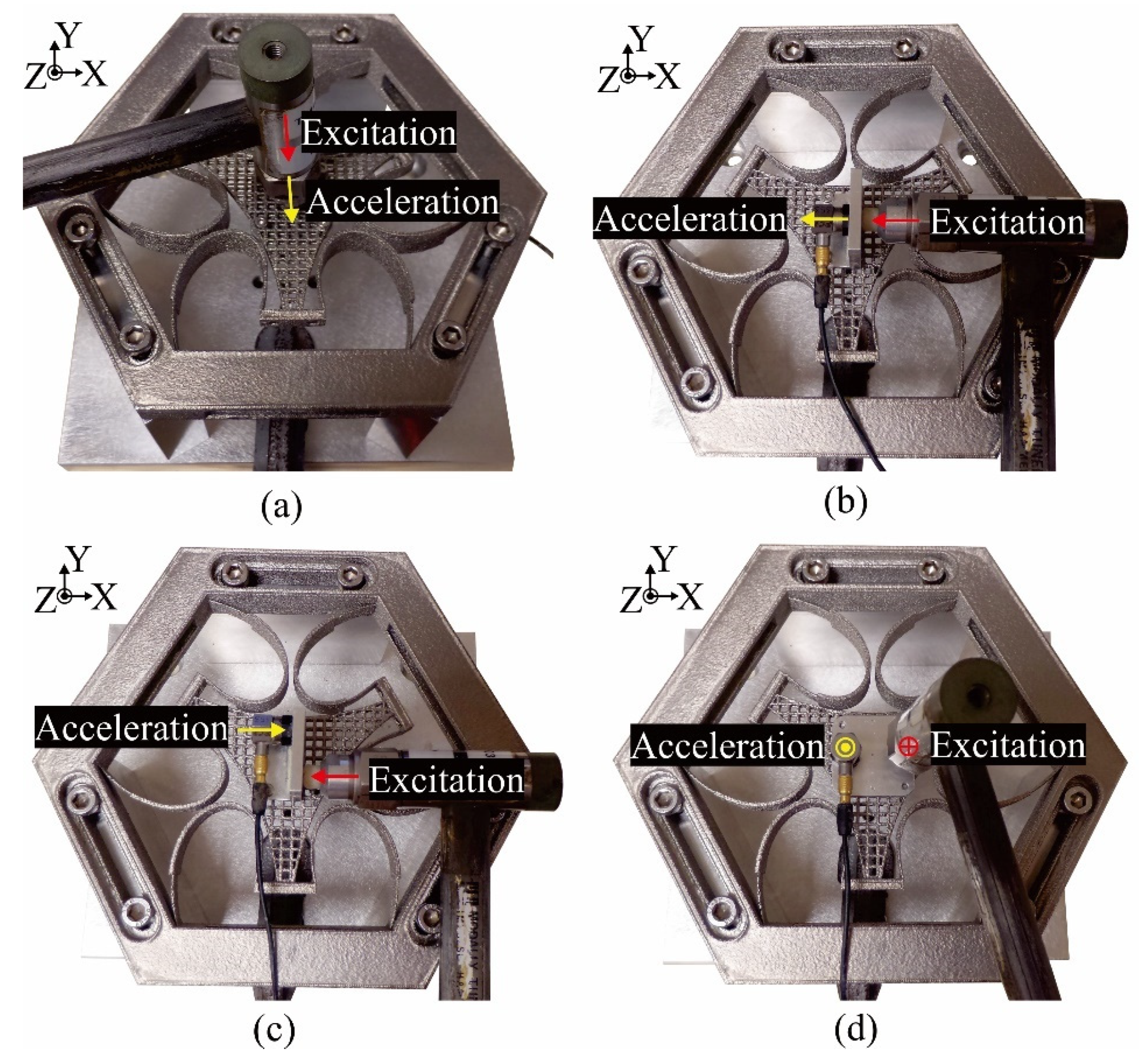
Referring to the experimental setups shown in
Figure 10, it is observed that some support parts were mounted on the end effector to attach the accelerometer and transmit the excitation to the CPM. As a result, the total mass of the end effector has increased due to the additional masses of support parts. These support parts were weighed by a precision balance (KERN 440-53N) and their masses were considered to accurately predict the dynamic behavior of the prototype that represented by the compensated frequency vector (
) shown in Equation (18). Note that the experimental results presented below will be compared to Equation (18).
Firstly, the evaluation for the first resonance mode along the Z axis was carried out. The accelerometer was attached below the end effector to measure the acceleration along the Z axis, an excitation in the same direction was applied by the impact hammer as shown in
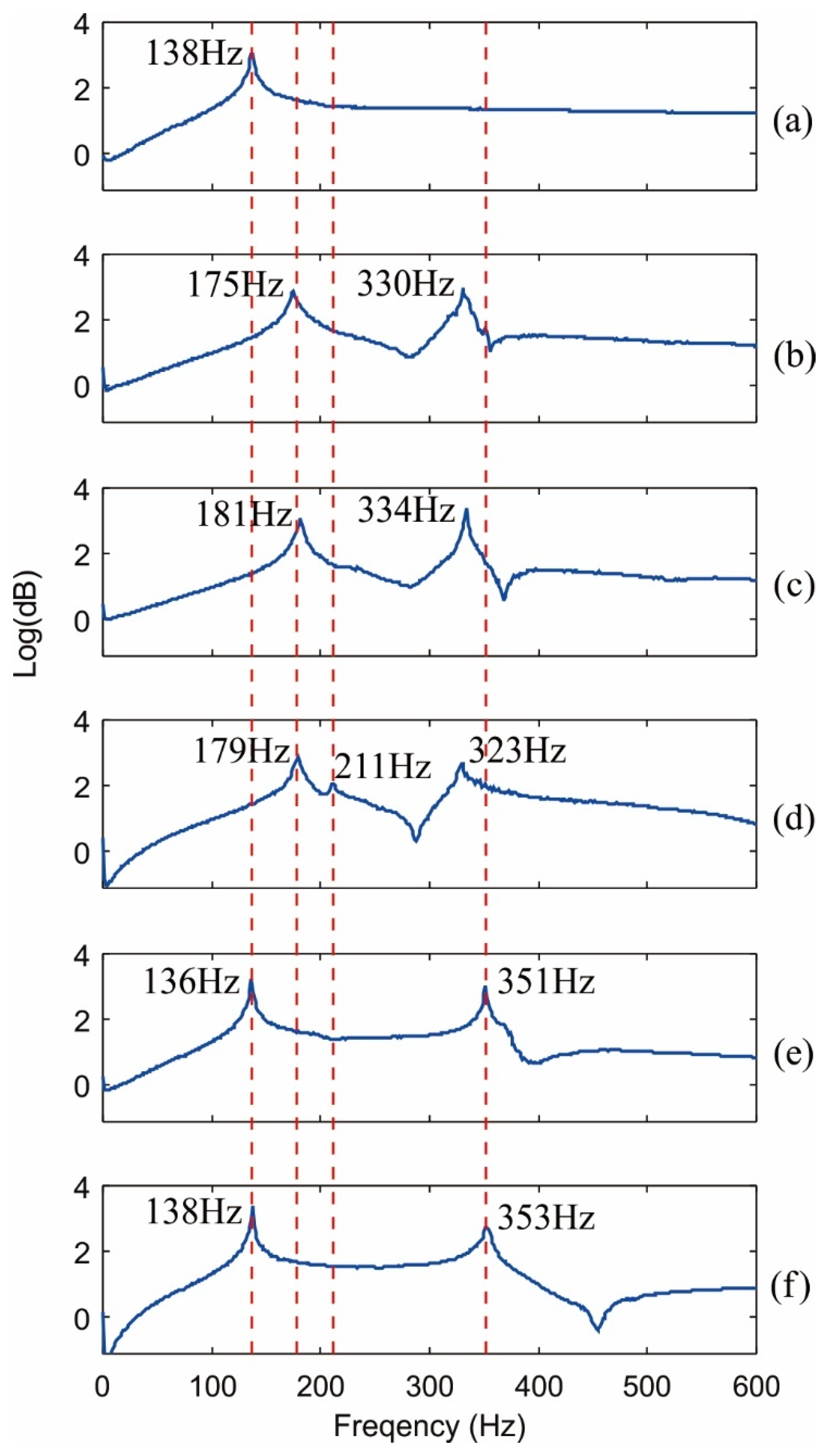
Figure 10a. The obtained result is plotted in
Figure 11a. It is seen that the experimental resonance frequency along the Z axis is 138 Hz, which has a small deviation of 3.5% compared to the predicted value of 143 Hz in Equation (18).
Next, the dynamic responses along the X and Y axes are evaluated.
Figure 10b shows the experimental setup to measure the dynamic response along the X axis. A L-shape support part was mounted on the top surface of the end effector. The accelerometer was attached to one side and the excitation was applied at the other side of the support part. Note that the directions of the acceleration and excitation are parallel to the X axis. Because the input force was measured at a specific distance along the Z axis from the end effector, a bending moment about the Y axis was also generated and the accelerometer was able to detect the response about the Y axis as well. Hence, the dynamic responses along the X axis and about the Y axis can be measured simultaneously by this experiment. Based on the obtained result plotted in
Figure 11b, two modes are clearly shown in the plot, the first peak represents the resonance frequency along the X axis while the second peak represents the resonance frequency about the Y axis. The measured dynamic response along the X axis is 175 Hz, which is close to the prediction of 191 Hz with the deviation of 8.38%. However, the measured resonance frequency about the Y axis of 330 Hz is significantly lower than the prediction of 361 Hz. Here, the difference is due to the non-ideal experimental setup to measure the dynamic response about the Y axis.
To overcome this limitation, a better setup which can measure the response about the Y axis more accurately is shown in
Figure 10d. A flat part used to attach the accelerometer was mounted on the end effector. The excitation was applied at a specific distance from the Y axis while the acceleration was measured at the opposite side. Since the directions of excitation and acceleration are along the Z axis, the first mode along the Z axis can also be detected by this setup. The obtained result is shown in
Figure 11f. It is seen that the first vibration mode is coincident with the previous measurement and the sixth vibration mode about the Y axis of 353 Hz well matches the prediction of 361 Hz with a small deviation of 2.22%. Two similar setups were adopted to measure the dynamic responses along the Y axis and about the X axis, the experimental results are plotted in
Figure 11c,e respectively.
Lastly, the fourth vibration mode (about the Z axis) of the CPM was evaluated by the setup shown in
Figure 10c. It is similar to the setup used to measure the response along the X axis but the accelerometer and impact position were shifted to two opposite sides of the support part. With this experimental setup, the dynamic responses along the X axis, about the Z and Y axes can be simultaneously measured and the obtained results are plotted in
Figure 11d. Similar to the previous setup shown in
Figure 10b, the response about the Y axis is lower than the prediction due to the non-ideal setup. The experimental dynamic responses together with the deviations compared to the predicted data are shown in
Table 2. It is seen that the highest deviation of the experimental results is less than 8.5%. This demonstrates that the use of cellular structure to construct the end effector is effective and the CPM has predictable dynamic property.
5. Conclusions
This paper presents a novel design of decoupled six-DOF CPM synthesized by the beam-based method with optimized dynamic characteristics by employing cellular structure. In particular, the cellular structure was applied to reduce the mass of the end effector as well as improve the dynamic behaviors of the CPM. With the cellular end-effector, the first resonance frequency of the CPM reaches 133 Hz, which is 33% higher than the design using the solid end-effector. In addition, the synthesized CPM is able to produce large workspace of ≥6 mm for the translations and ≥12° for the rotations.
Some experiments were carried out to verify the actual performance of the CPM prototype. The experimental results show that the characteristic of the prototype well agrees with the predicted data with the highest deviations of 10.47% and 8.38% for the stiffness and dynamic properties respectively. Moreover, the CPM is able to produce full workspace and the measured six vibration modes well match the prediction. The CPM in this work is constructed by 90°-oriented curved beam and its decoupled motions were also demonstrated, the experimental results suggest that the energies of parasitic motions only contribute less than 0.4% over the total input energy. Together with the previous work [
25], all design criteria for synthesizing CPMs with motion decoupling capability [
25] have been fully verified.
The synthesized CPM is able to produce large workspace based on the elastic deformation of the curved beams. However, the buckling of such long beams has not been considered. Hence, bucking analysis will be carried out in future based on relevant models presented in [
29,
30]. The results obtained from this work demonstrate that all six vibration modes of a CPM can be accurately predicted. Nevertheless, only the first resonance frequency was successfully optimized to the targeted value at this stage of the research. Therefore, the future work focuses on optimizing all six primary resonance frequencies as well as further exploiting the advantages of cellular structures in improving the dynamic characteristic for CPMs. The density of cellular structure, represents by
VR in this work, can be considered in the design process of CPMs in order to achieve desired dynamic behaviors. Moreover, the merits of 3D printing technologies, i.e., the ability to build complex structures and fabricate multiple materials in a single part, will be further investigated to develop new compliant devices with enhanced performances through lattice flexures, free-form flexible structures, multi-material CPMs, etc. The prediction and compensation models for manufacturing errors of 3D printing techniques should also be explored.


