Abstract
This paper proposes a method for improving machine tool linear feed system accuracy by considering the geometric error shape of the guideway. First, a mathematical model relating guideway errors to worktable pose errors is established using static force equilibrium principles and deformation coordination equations. The impact of different guideway geometric error-shape combinations of linear feed system accuracy is analyzed. It is determined under which combination of guideway error shapes the linear feed system achieves the highest accuracy. Second, a finite element analysis model of the machine tool linear feed system is developed to examine how guideway geometric error shapes affect the error-averaging effect. This is compared with conventional design methods that disregard error shapes. Finally, experimental verification confirms both the effectiveness and broader applicability of the guideway error-shape design methodology. The results show that controlling the error shape of guideways can relax the requirement for guideway amplitude, thereby reducing machining difficulty and production costs.
1. Introduction
As the requirements for machining accuracy increase, the demands placed on machine tool precision is also increasing [1]. The precision of machine tool linear feed systems is affected by multiple factors, including assembly, positioning, and machining errors. Among these, manufacturing and assembly errors in guideways prove particularly critical [2,3]. These errors cause spatial positioning and orientation deviations in the worktable during motion, rather than ideal linear movement. Due to multiple types of guideway errors and their interactions, both the accuracy and stability of the feed system are compromised. Therefore, studying the relationship between guideway geometric errors and positioning errors is essential for improving machine tool feed system precision. In response to this challenge, numerous scholars have conducted extensive research and proposed various effective methods for error suppression.
Accuracy design of machine tool feed systems is an important method for error suppression, and numerous researchers have proposed various accuracy design methodologies. Fan et al. [4] established a mathematical model for sliders geometric error induced by contact deformation from guideway wear, suppressing geometric errors by predicting guideway wear progression. Khim et al. [5] proposed a machining algorithm that repetitively measures linear and angular motion errors, enhancing guideway accuracy by estimating motion error equivalent guideway error shapes. Shamoto et al. [6] proposed a method of predicting guideway contour error using oil film reaction forces, and of suppressing guideway error by eliminating the estimated contour error shape through scraping and other methods. Ma et al. [7] and Wu et al. [8] introduced a mathematical theoretical model of the impact of guideway assembly errors of the precision of linear feed systems. This model calculates the positional and angular deviations of the worktable under three distinct conditions: manufacturing error conditions, structural influence conditions, and actual conditions. Based on this, a method is proposed for reducing guideway errors. Zha et al. [9] proposed a method for modeling and compensating for straightness errors. A model of errors was created using a method of averaging error based on pressurized oil films. This model suppressed errors in hydrostatic guideways. Guo et al. [10] analyzed outputs from geometric error vectors within the linear feed system workspace, using a method analyzing error sensitivity to determine the impact of guideway geometric errors on linear feed system precision and improved precision by suppressing important errors. Wu H et al. [11,12] proposed a tolerance-optimization model for static geometric precision of motion guideways in CNC machine tool linear axes. Optimization of guideway assembly tolerances enhanced machining accuracy from a tolerance design perspective. Wang et al. [13] introduced a geometric accuracy-optimization method using B-splines which clarifies the relationships involving spatial errors, geometric errors, and guideway setting errors. Through a collaborative swarm intelligence algorithm, parallel optimization of guideway shape and dimensions was realized to suppress guideway errors.
Error-averaging effects must be considered during accuracy design of feed systems. Park et al. [14,15] established an error model for hydrostatic guideways, analyzing the relationship between slider posture deviation under a single error shape and guideway assembly errors using the finite element method. This work theoretically quantified the error propagation effect of oil films on motion errors, thereby providing a valuable insight into the dynamics of such systems. Wang et al. [16] established a mathematical model for error propagation between guideway construction errors and geometric errors of movement components based on the rigid body assumption, thereby unveiling the error-averaging principle in machine tool linear feed systems. Ni et al. [17] analyzed the error-averaging mechanism of rolling guideway pairs under roller deformation, quantified the error-averaging effect in rolling guideway systems, and established a four-slider static model reflecting the impact of error-averaging effects on pose error of motion pairs. Sun et al. [18] considered elastic deformation in linear feed systems and performed finite element analysis to determine how the error-averaging mechanism is affected by guideway geometric errors. The analysis indicates that the straightness error in the vertical direction of the guideway significantly affects the error-averaging mechanism. Song et al. [19] established an error motion calculation model for closed hydrostatic guideways with external sliders, analyzed the distribution of error-averaging coefficients, and used averaging coefficients to constrain guideway design and assembly processes. Lin et al. [20] analyzed error transmission laws through a finite element model based on spring elements, deriving an assembly process to improve moving-component precision. Hu et al. [21] proposed the generality of error-averaging for enhancing moving-platform accuracy in parallel mechanisms, demonstrating the importance of error-averaging effects for machine tool accuracy design.
However, previous studies on feed system accuracy design have not considered the influence of guideway geometric error shape. This paper proposes an extensive investigation into the effects of guideway geometric error-shape pairing on pose errors in machine tool feed systems and proposes an accuracy design methodology incorporating error-shape considerations. The remaining content is structured as follows. Section 2 establishes a linear feed system error model via the static force equilibrium method, analyzing worktable pose error under different error-shape combinations. It further enhances guideway error amplitudes under the optimal combination and compares them with worktable pose error without shape design. Section 3 presents a finite element model and uses simulations to establish the applicability and generalizability of the methodology. Section 4 details the implementation of experiments on a machine tool linear feed system, with experimental data providing verification of the guideway error-shape accuracy design proposed in this study. Conclusions are presented in Section 5. The specific flowchart of this paper is presented in Figure 1.
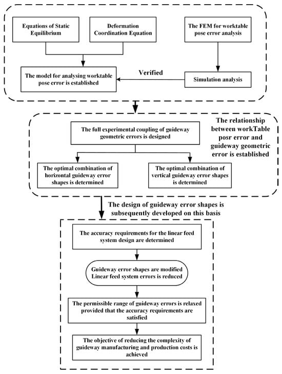
Figure 1.
Flowchart for design methodology of guideway geometric error shapes.
2. Theoretical Analysis
This study focuses on the linear feed system of a typical double-guide four-slider structure in machine tools. The worktable pose error is determined through static equilibrium equations and deformation coordination equations. First, the combination forms of machine tool error shapes are analyzed, and the worktable pose error under various error shapes are calculated. Second, the resulting data revealing the influence mechanism between worktable pose error and guideway errors is analyzed. Finally, the optimal shape matching of guideway geometry error to suppress worktable motion error is obtained through analysis of the results.
2.1. Theoretical Model
As shown in Figure 2, the geometric error of the guideway impacts the pose error of the linear feed system, which red denotes the vertical direction and blue denotes the horizontal direction. Based on the static equilibrium method, the mechanical equilibrium equation can be obtained as shown in Equation (1).
where Ph1, i, Ph2, i, Ph3, I, and Ph4, i are the reverse elastic force in the horizonal direction generated by the installation of the slider on the guideway. Pv1, i, Pv2, i, Pv3, I, and Pv4, i are the reverse elastic force in the vertical direction generated by the installation of the slider on the guideway. Fz and Fy are the forces applied by the worktable in the vertical and horizonal directions. The moments acting on the worktable in the X-direction, Y-direction, and z Z-direction are represented by Mx, My, and Mz, respectively.
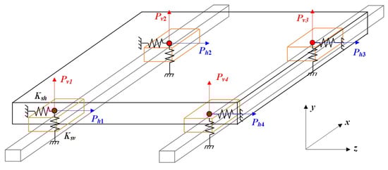
Figure 2.
Force analysis of the worktable feed system.
Solving pose errors in linear feed systems requires applying deformation coordination equations in addition to static equilibrium equations [22]. The deformation compatibility equation can be obtained by following this process, given that the table is rigid, as shown in Equation (2).
where l1 and l2 denote the straight-line distances between slider 1 and slider 2 in the horizontal direction, and between slider 2 and slider 3 in the horizontal direction, respectively. eh1(xi) and eh2(xi) denote the horizontal-direction guideway geometric error shapes at the guideway locations of slider 1 and slider 4, respectively. eh1(xi+l1) and eh2(xi+l1) denote the horizontal-direction guideway geometric error shapes at the guideway locations of sliders 2 and 3, respectively. Similarly, ev1(xi) and ev2(xi) denote the vertical-direction guideway geometric error shapes at the guideway locations of slider 1 and slider 4, respectively. ev1(xi+l1) and ev2(xi+l1) are the vertical geometry error shapes of the guide rails at the locations of sliders 2 and 3, respectively. δh1, i, δh2, i, δh3, i, δh4, i, and δh0, i denote the horizontal elastic deformation caused by the mutual contact between sliders 1 to 4 and the guideways, as well as the horizontal elastic deformation of the worktable. In contrast, δv1, i, δv2, i, δv3, i, δv4, I, and δv0, i denote the vertical elastic deformation.
The error relationship between the guideway and the slider is shown in Figure 2 and Figure 3. By combining the deformation coordination equation and the static equilibrium equation, the precision error of the linear feed system can be solved, as shown in Equation (3).
where Ksh and Ksv denote the equivalent stiffness in the vertical and horizontal directions of the sliders, respectively.
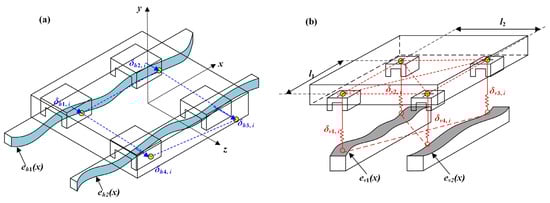
Figure 3.
Relationship between slider elastic deformation and guideway error: (a) Horizontal-direction elastic deformation; (b) Vertical-direction elastic deformation.
2.2. Analysis of the Geometric Error Shape of Guideways
Three common error shapes exist in guideways: sine-shaped errors, arch-shaped errors, and incremental-shaped errors, as shown in Figure 4. Due to the periodic nature of incremental-shaped errors, they are the same as arch-shaped errors in performing analysis, considered as half an arch-shaped error. This paper exclusively analyzes the interaction effects of arch-shaped error and sine-shaped error combinations on pose error in rolling guideway feed systems.
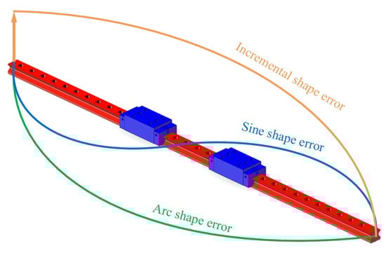
Figure 4.
Guideway error shape.
2.3. Full Experimental Design of Guideway Error Shapes
The model in this paper is established using THKSRGR45 linear rolling guideways. The material parameters of the guideways can be found in the THK guideway manual, and the specific parameters are shown in Table 1.

Table 1.
Feed system parameters.
The formulas for positive and negative arch-shaped errors of the guideway are as follows (Equations (4) and (5)).
The formulas for positive and negative sine-shaped errors of the guideway are as follows (Equations (6) and (7)).
where Z denotes the position of the worktable center during movement.
The linear feed system described in this paper includes two guideways, each of which contains two types of errors: arch-shaped errors and sine-shaped errors. To analyze the impact of the guideway geometric error shapes on the accuracy of the linear feed system, the full experiment is designed with two guideways as the factor and four error types as the levels [23], as shown in Table 2 and Table 3 and Figure 5. In Figure 5, the red curve represents errors applied in the vertical direction, while the blue curve represents errors applied in the horizontal direction.
Table 2.
Vertical error full experiment.
Table 3.
Horizontal error full experiment.
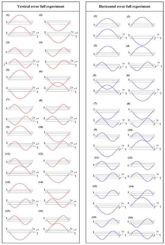
Figure 5.
Guideway error arrangement.
2.4. Analysis of Theoretical Results
Vertical guideway errors impact worktable pitch error, roll error, and vertical straightness error. Horizontal guideway errors affect worktable yaw error and horizontal straightness error. According to the error-coupling test results in Table 2 and Table 3, combined with Equation (3), the X-direction straightness error, the Y-direction straightness error, the yaw error, the pitch error, and the roll error are calculated. The results are shown in Table 4.
Table 4.
Theoretical calculation results.
It is permissible to present the following conclusions, according to data presented in Table 4. Under vertically opposed identical error shape on dual guideways, Y-direction straightness errors undergo mutual cancelation, thereby minimizing worktable pitch error. Under identical vertical error shape with aligned orientation on dual guideways, worktable roll error is minimized. Under horizontally opposed identical error shape on dual guideways, both X-direction straightness errors and yaw errors undergo mutual cancelation. It can be concluded that identical guideway error shape with opposing direction provide optimal suppression of pose errors in linear feed systems.
3. Finite Element Analysis
3.1. Single-Slider Modeling
In the finite element simulation of linear rolling guideway pairs, the equivalent method for the contact stiffness of rolling elements is the most important. To simulate various guideway geometric errors, rolling elements are modeled as spring elements. Compression and extension of these springs modify the guideway contact surface geometry, thereby generating different geometric error types, as shown in Figure 6.
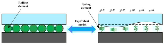
Figure 6.
Relationship between rolling element equivalence and guideway geometric errors.
The contact interface geometry between the rolling element and raceway can be modified by adjusting parameter g. The first length of the equivalent spring between the contact surface of each rolling element and the raceway can be formulated as follows (Equation (8)).
The parameter d denotes the original size of the rolling part, while g denotes the combined error of the guideway (assuming zero initial guideway error), and δ0 denotes the preload of the slider.
Guideway geometric error shape demonstrates complex, coupled, and variable characteristics, requiring simultaneous consideration of multiple error parameters. Consequently, error-coupling effects are examined by varying the straightness error magnitudes and phases on both guideways. Finite element models of all constituent components are established in the simulation software ABAQUS 6.14, followed by meshing procedures. During finite element simulation analysis, rolling elements at the guideway–slider contact surfaces are simplified into nonlinear line connection elements, as shown in Figure 7 and Figure 8.
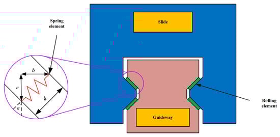
Figure 7.
Equivalent model of contact between guideway raceway and slide.
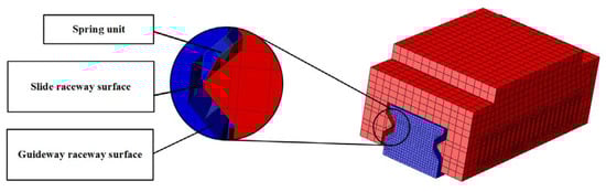
Figure 8.
Geometric relationship between the slider roller and the raceway surface.
Finite element analysis characterizes worktable pose errors at various guideway positions during motion through static simulation of dynamic conditions, enabling investigation of guideway geometric error-shape impacts on linear feed system precision, as shown in Figure 9.
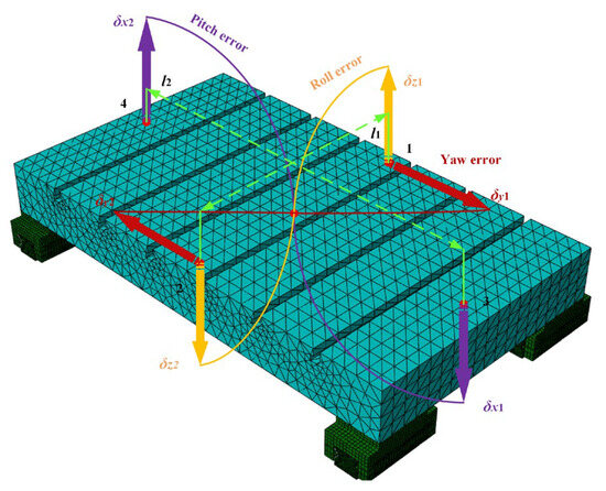
Figure 9.
Finite element model for solving worktable pose errors.
In the coordinate system where the linear feed system is located, the z-direction is defined as the positive direction of movement. The worktable pose error at each position is calculated using the simulation results of the worktable at that position.
The yaw error is calculated as shown in Equation (9).
The pitch error is calculated as shown in Equation (10).
The roll error is calculated as shown in Equation (11).
where l1 is the horizontal length between data point 1 and data point 2, and l2 is the horizontal length between data point 3 and data point 4.
3.2. Analysis of Finite Element Simulation Result
The worktable pose error under different guideway error combinations is analyzed and solved by using finite element analysis. The finite element results are shown in Table 5.
Table 5.
Results of the worktable pose error by finite element analysis.
The correctness of the theoretical model is verified by comparing the variation trends of pose errors between the theoretical results and the finite element results. According to the conclusions from Section 2, the variation trends of various error shapes are compared in vertical experiment 5 to experiment 8 and horizontal experiment 2, experiment 5, experiment 11, and experiment 16. The results are shown in Figure 10 and Figure 11.
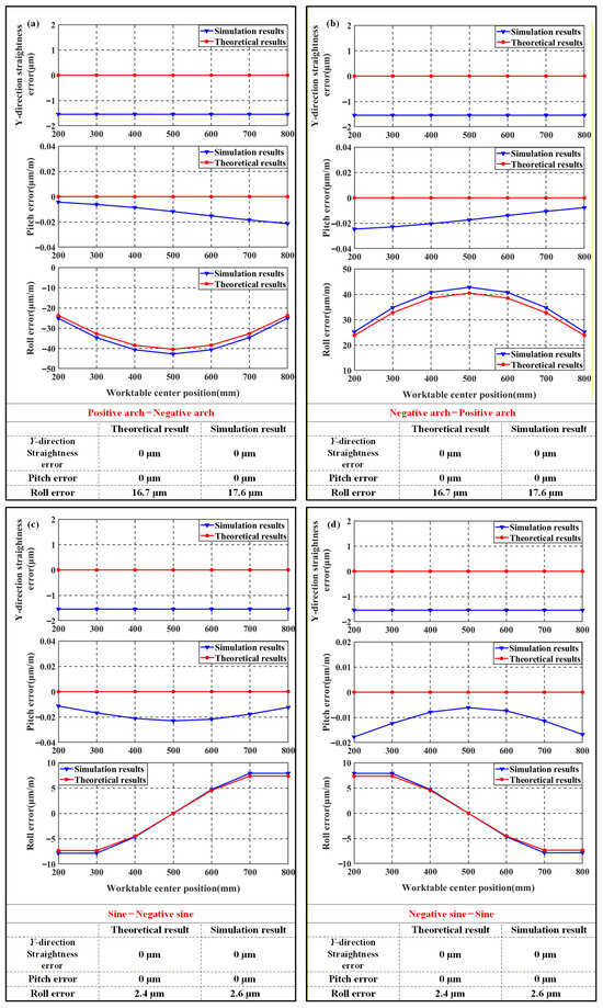
Figure 10.
Comparison of vertical finite element results with theoretical results: (a) Vertical experiment 5; (b) Vertical experiment 6; (c) Vertical experiment 7; (d) Vertical experiment 8.
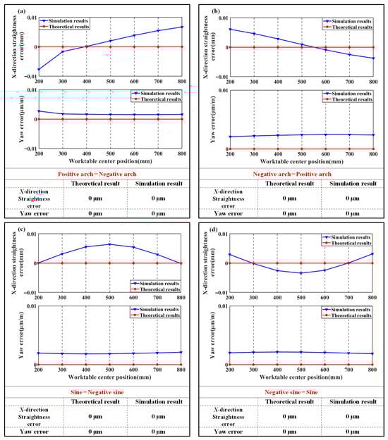
Figure 11.
Comparison of horizontal finite element results with theoretical results: (a) Horizontal experiment 2; (b) Horizontal experiment 5; (c) Horizontal experiment 11; (d) Horizontal experiment 16.
From Figure 10, it can be seen that under identical arch-shaped geometric error with opposing directions on Y-direction guideways, both straightness and pitch errors of the machine tool worktable are minimized, while significant roll error occurs with measured values of 42.76 μm/m and 42.78 μm/m, respectively. Under identical sine-shaped guideways with opposing direction in the Y-direction, both straightness and pitch errors approach zero, while roll error remains below arch-profile levels at measured values of 7.983 μm/m and 7.897 μm/m.
Figure 11 shows that under identical arch-shaped geometric error shape with opposing direction on X-direction guideways, machine tool straightness and yaw errors are minimized. During application of sine error shapes with identical form and opposite directions to X-direction guideways, X-direction straightness and pitch errors similarly approach near-zero values.
However, Table 4 and Table 5 reveal significant discrepancies in yaw error between simulation and theoretical results. This divergence stems from the theoretical model neglecting elastic deformation effects on worktable pose errors, while the finite element analysis treats the entire assembly as an elastic body. Data normalization enables clearer comparison of trend variations between theoretical and finite element models, as shown in Figure 12.
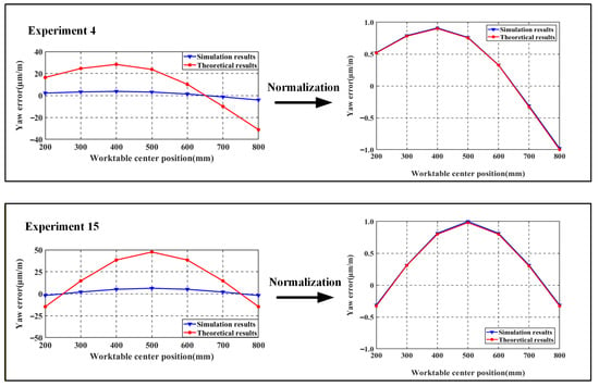
Figure 12.
Yaw error comparison plot.
By comparing the trends in the four sets of yaw error changes, it can be observed that the theoretical model results are consistent with the trends in the finite element calculation results, which proves the correctness of the above theory and establishing a theoretical basis for the guideway error shapes that will be designed subsequently. The roll error value is less than 15% of the theoretical error and the trend of change is consistent with the theoretical results.
3.3. Error-Averaging Coefficient Analysis
The ratio of the worktable pose error to the guideway error is regarded as the error-averaging coefficients, as shown in Equation (12).
where nX and nY denote the error-averaging coefficients for X- and Y-directions. δg denotes the geometric errors of guideways.
Table 6 lists error-averaging coefficients under various guideway error-coupling conditions. The error transmitted to the worktable is minimal where the guideway errors are combined in the same form but in opposite directions.
Table 6.
Error-averaging coefficient under various error conditions of guideways.
3.4. Design of Guideway Error Shapes
Building on the integration of the impact of guideway error shape on error-averaging coefficients (Section 3) with guideway shape design effects on worktable pose errors (Section 2), this section conducts a comparative analysis between conventional and profile-based guideway error design methods, as shown in Figure 13.
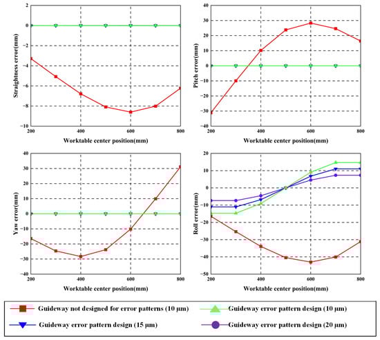
Figure 13.
Comparison of guideway errors in geometric error-shape design.
Analysis of the above results reveals the following:
Compared with traditional guideway error design methods, the error-shape design method incorporates consideration of counterbalancing effects between initial errors on dual guideways. Under the condition of identical error shape with opposing direction on dual guideways, mutual cancelation of guideway errors occurs, resulting in near-zero pose errors at the worktable.
This error-shape-based design methodology allows increasing guideway error amplitudes from 10 μm to 20 μm while maintaining equivalent worktable motion accuracy. The amplified errors remain smaller than those in conventional non-profile-optimized guideway configurations.
4. Experiment Verification
Experimental validation is conducted to investigate the influence of geometric error shapes in rolling guideway assemblies on worktable pose errors. Comparative analysis is performed against the aforementioned accuracy design method theory and simulation results.
4.1. Experimental Setup
The experiments are conducted within an environment that maintain a constant temperature of 20 ± 0.5 °C. To investigate the impact of guideway error shapes on machine tool linear feed system accuracy design, a dedicated test bench is developed, as shown in Figure 14. Worktable pose errors are measured using a laser interferometer, while straightness of guideways and the worktable are measured using an Optical collimator. Specifications of required instruments are listed in Table 7.
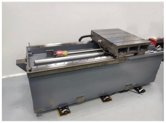
Figure 14.
Experimental test platform.
Table 7.
Experimental apparatus.
To identify straightness errors on each mounting surface, numerous additional devices are required, as shown in Table 7.
The experimental procedure comprised three stages. First, geometric errors of guideways and the worktable are measured to ensure high initial accuracy is achieved. These measurements are used to eliminate pre-existing worktable pose errors. Second, the geometric errors of the horizontal guideways are modified. Finally, in the experimental stage, worktable pose errors are measured using identical procedures, with subsequent result analysis. Measurement methodologies for worktable pose errors and straightness errors are shown in Figure 15.
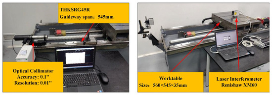
Figure 15.
Error measurement method.
4.2. Experimental Results
4.2.1. Analyzing Guideways Without Additive Geometric Errors
First, the original straightness errors of the guideways were measured using an Optical collimator, with results shown in Figure 16. In the vertical direction, maximum error values for the left and right guideways measured 4.9 μm and 0.56 μm, respectively. In the horizontal direction, maximum errors measured 1.45 μm and 1.25 μm, respectively.
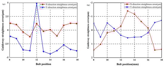
Figure 16.
Straightness error of guideways without additional geometric errors: (a) left guideway; (b) right guideway.
Following initial guideway error measurement, the worktable was mounted. Straightness errors and pose errors of the worktable were measured using an Optical collimator and laser interferometer, respectively. The worktable traversed ten steps along the guideway with 100 mm per step. Initial worktable errors were obtained as shown in Figure 17. Maximum X-direction and Y-direction straightness errors measured 5.12 μm and 8.97 μm, respectively. Maximum yaw error, pitch error, and roll error values measured 9.95 μm/m, 32.871 μm/m, and 6.33 μm/m, respectively.
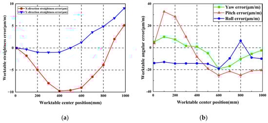
Figure 17.
Worktable errors without additional geometric errors: (a) Worktable straightness error; (b) Worktable pose error.
To modify the geometric error shapes of the guideway, feeler gauges are inserted at midpoints between adjacent screws uniformly distributed between the guideway base surface and the guideway. Different geometric error shapes of the guideway are simulated by varying feeler gauge specifications, with gauge dimensions and shimming configurations shown in Figure 18.
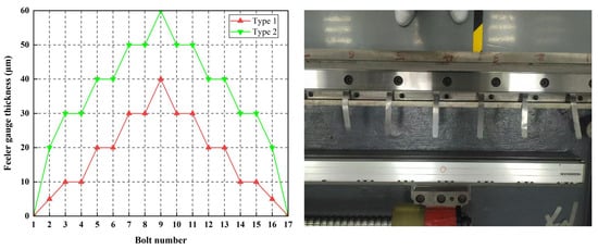
Figure 18.
Feeler gauge arrangement method.
4.2.2. Identical Horizontally Arched Geometrishijiaxiangtongc Error of Guideway Is Applied
To modify the error shape in the Y-direction of the guideway to an arch-shaped error, shimming is performed between the guideway base surface and the guideway using feeler gauges. Measurements are conducted with 40 μm specification feeler gauges, employing methodologies identical to Step 1; the outcomes are shown in Figure 19 and Figure 20.
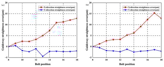
Figure 19.
Straightness error of guideways with identical positive arched errors: (a) left guideway; (b) right guideway.
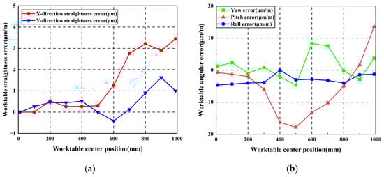
Figure 20.
Worktable errors with identical positive arched errors: (a) Worktable straightness error; (b) Worktable pose error.
Measurement results indicate maximum straightness errors in the horizontal direction measured 14.71 μm and 15.19 μm for the left and right guideways, respectively. Maximum worktable straightness error and yaw error measured 3.45 μm/mm and 8.33 μm/mm, respectively.
4.2.3. Reverse Horizontally Arched Geometric Error of Guideway Is Applied
By using the 40 μm feeler gauge, the horizontal errors of the two guideways are modified into a positive arch–negative arch error shape. The geometric errors of the guideways are measured using the same method as in Step 1, as shown in Figure 21 and Figure 22.
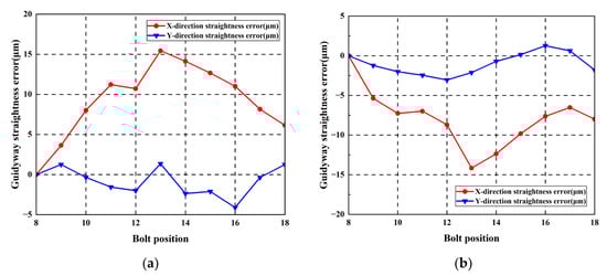
Figure 21.
Straightness error of guideways with 40 μm reverse arched errors: (a) left guideway; (b) right guideway.
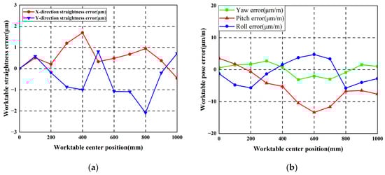
Figure 22.
Worktable errors with 40 μm reverse arched errors: (a) Worktable straightness error; (b) Worktable pose error.
Measurement results show that maximum straightness errors in the horizontal direction measured 15.44 μm and 14.16 μm for the left and right guideways, respectively. Maximum worktable straightness error and yaw error measured 1.69 μm/mm and 3.15 μm/mm, respectively.
Subsequently, larger guideway errors are simulated by increasing the feeler gauge size, while the experimental procedure remains unchanged. The guideway errors and the worktable pose error are measured, as shown in Figure 23 and Figure 24.
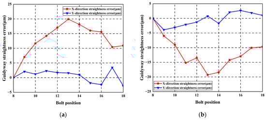
Figure 23.
Straightness error of guideways with 60 μm reverse arched errors: (a) left guideway; (b) right guideway.
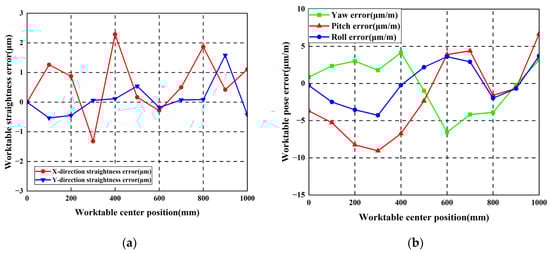
Figure 24.
Worktable errors with 60 μm reverse arched errors: (a) Worktable straightness error; (b) Worktable pose error.
Measurement results show that maximum straightness errors in the horizontal direction measured 19.92 μm and 19.28 μm for the left and right guideways, respectively. Maximum worktable straightness error and yaw error measured 2.29 μm/mm and 6.56 μm/mm, respectively.
4.2.4. Analysis of Experimental Results
To verify that machining linear feed system tolerance requirements can be relaxed through guideway shape design, the worktable X-straightness error and yaw error under positive arch–positive arch horizontal error and positive arch–negative arch horizontal error are compared, as shown in Figure 25.
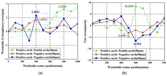
Figure 25.
Worktable error comparison results: (a) X-straightness error; (b) Yaw error.
It can be seen from Figure 25 that after guideway error design is implemented in the horizontal direction, the worktable straightness error and yaw error are both smaller than those without guideway error design, compared to the worktable pose error without guideway error design. After the amplitude of the geometric errors of the guideways following guideway error design is enlarged, a similar level of accuracy to the linear feed system without guideway error design can still be maintained. This demonstrates the effectiveness of performing guideway error-shape design and analysis and verifies the correctness of the theoretical and finite element results.
5. Conclusions
This paper proposed an accuracy design method incorporating geometric error shape for linear feed systems, investigated through theoretical analysis, simulation, and experimental validation. The following conclusions are drawn:
- (1)
- The research results indicate that the pose error of the worktable is influenced by the amplitude and shape of the guideway geometric errors in the linear feed system. Consequently, conducting guideway shape design is meaningful.
- (2)
- The highest accuracy for the linear feed system is achieved under the guideway condition of sine–negative sine or positive arch–negative arch error shapes in the horizontal direction, and under the condition of sine–negative sine error shapes in the vertical direction.
- (3)
- Implementing accuracy design based on the optimal guideway shape combination significantly relaxes the geometric tolerance requirements for guideways, thereby reducing manufacturing difficulty and production costs.
- (4)
- The proposed accuracy design method provides a valuable reference for the development and manufacturing of other precision equipment.
Author Contributions
Methodology, Conceptualization, Project administration, Writing—original draft, Writing—review and editing, Funding acquisition, X.G.; Writing—original draft, Data curation, Formal analysis, Methodology, Validation, H.W.; Data curation, Visualization, Validation, G.S.; Supervision, Writing—review and editing, D.Z.; Data curation, Validation, Z.S.; Data curation, Visualization, G.H. All authors have read and agreed to the published version of the manuscript.
Funding
This work was supported in part by the Shenyang Science and Technology Major Special Project (No. 23-401-1-01); the National Nature Science Foundation of China under Grant No. U23B20102 and No. 52205535; and the Tianjin Natural Science Foundation Project 25JCYBJC00260 and 22JCQNJC01000, Tianjin Science and Technology Plan Project 24PTLYHZ00030, Tianjin Key Laboratory of High-Performance Manufacturing Technology and Equipment (TUTE) Open Research Projects (No. TKL-TUTE2501).
Data Availability Statement
The original contributions presented in this study are included in the article. Further inquiries can be directed to the corresponding author.
Conflicts of Interest
The authors declare that they have no known competing financial interests or personal relationships that could have appeared to influence the work reported in this paper.
References
- Liu, C.; Zheng, P.; Xu, X. Digitalisation and servitisation of machine tools in the era of Industry 40: A review. Int. J. Prod. Res. 2023, 61, 4069–4101. [Google Scholar] [CrossRef]
- Ilangkumaran, M.; Sasikumar, R.; Sakthivel, G. Parametric optimization for the production of nanostructure in high carbon steel chips via machining. Ain Shams Eng. J. 2015, 6, 957–965. [Google Scholar] [CrossRef]
- Yang, K.Z.; Pramanik, A.; Basak, A.; Dong, Y.; Prakash, C.; Shankar, S.; Dixit, S.; Kumar, K.; Vatin, N.I. Application of coolants during tool-based machining—A review. Ain Shams Eng. J. 2023, 14, 101830. [Google Scholar] [CrossRef]
- Fan, K.C.; Chen, H.M.; Kuo, T.H. Prediction of machining accuracy degradation of machine tools. Precis. Eng. 2012, 36, 288–298. [Google Scholar] [CrossRef]
- Khim, G.; Park, C.H.; Shamoto, E.; Kim, S.W. Prediction and compensation of motion accuracy in a linear motion bearing table. Precis. Eng. 2011, 35, 393–399. [Google Scholar] [CrossRef]
- Shamoto, E.; Park, C.H.; Moriwaki, T. Analysis and improvement of motion accuracy of hydrostatic feed table. CIRP Ann. 2001, 50, 285–290. [Google Scholar] [CrossRef]
- Ma, J.; Lu, D.; Zhao, W. Assembly errors analysis of linear axis of CNC machine tool considering component deformation. Int. J. Adv. Manuf. Technol. 2016, 86, 281–289. [Google Scholar] [CrossRef]
- Wu, J.; Wang, J.; Wang, L.; Li, T.; You, Z. Research on the stiffness of a 5-DOF hybrid machine tool with actuation redundancy. Mech. Mach. Theory 2009, 44, 289–305. [Google Scholar] [CrossRef]
- Zha, J.; Xue, F.; Chen, Y.L. Straightness error modeling and compensation for gantry type open hydrostatic guideways in grinding machine. Int. J. Mach. Tools Manuf. 2017, 112, 1–6. [Google Scholar] [CrossRef]
- Guo, S.; Mei, X.; Jiang, G. Geometric accuracy enhancement of five-axis machine tool based on error analysis. Int. J. Adv. Manuf. Technol. 2019, 105, 137–153. [Google Scholar] [CrossRef]
- Wu, H.; Li, X.; Sun, F.; Zheng, H.; Zhao, Y. Optimization design method of machine tool static geometric accuracy using tolerance modeling. Int. J. Adv. Manuf. Technol. 2022, 118, 1793–1809. [Google Scholar] [CrossRef]
- Wu, H.; Zheng, H.; Li, X.; Wang, W.; Xiang, X.; Meng, X. A geometric accuracy analysis and tolerance robust design approach for a vertical machining center based on the reliability theory. Measurement 2020, 161, 107809. [Google Scholar] [CrossRef]
- Wang, S.; He, G.; Zhang, D.; Yang, Y.; Yan, Y.; Song, Y. B-Spline Curve-Based Machine Tool Guideways Geometric Accuracy Design. Int. J. Mech. Sci. 2025, 301, 110550. [Google Scholar] [CrossRef]
- Park, C.H.; Jeong, J.H.; Lee, H.S.; Kim, S.T. Finite Element Analysis on the Motion Accuracy of Hydrostatic Table (1st Analysis and Experimental Verification on Single-side Table). J. Korean Soc. Precis. Eng. 2000, 17, 137–144. [Google Scholar]
- Park, C.H.; Lee, H.S.; Kim, T.H.; Kim, M.G. Finite Element Analysis on the Motion Accuracy of Hydrostatic Table (2nd Analysis and Experimental Verification on Double Sides Table). J. Korean Soc. Precis. Eng. 2002, 19, 65–70. [Google Scholar]
- Wang, S.; He, G.; Zhang, D.; Chen, F.; Yao, C.; Yan, Y. Innovative design methods for the geometric accuracy of machine tool guideway oriented to spatial accuracy. J. Manuf. Process. 2024, 119, 483–498. [Google Scholar] [CrossRef]
- Ni, Y.; Zhou, H.; Shao, C.; Li, J. Research on the error averaging effect in a rolling guide pair. Chin. J. Mech. Eng. 2019, 32, 72. [Google Scholar] [CrossRef]
- Sun, G.; Chen, S.; Sun, M.; Gao, R.; Zhang, D.; Guo, X.; Zhao, J. Research on the error averaging effect of linear feed systems for precision machine tools. Ain Shams Eng. J. 2024, 15, 103101. [Google Scholar] [CrossRef]
- Song, L.; Zhang, Q.; Xu, L.; Zhao, X.; Sun, T. Investigation of the error averaging effect on design and assembly of external slider closed hydrostatic guideways. Tribol. Int. 2024, 199, 110036. [Google Scholar] [CrossRef]
- Lin, Z.; Tian, W.; Zheng, Y.; Xu, Y.; Shi, K.; Chen, J.; Zhang, D.; Gao, W. Analysis of the Finite Element Simulation of the Linear Rolling Guide Pair Error Averaging Effect. In Artificial Intelligence Technologies and Applications; IOS Press: Amsterdam, The Netherlands, 2024; pp. 200–206. [Google Scholar]
- Hu, P.H.; Yu, C.W.; Fan, K.C.; Dang, X.M.; Li, R.J. Error averaging effect in parallel mechanism coordinate measuring machine. Appl. Sci. 2016, 6, 383. [Google Scholar] [CrossRef]
- Sun, G.; Wang, Y.; Wang, W.; Liu, J.; Yu, M.; Zhao, J. Stiffness effects on repeatability of positioning of linear axes. J. Mech. Sci. Technol. 2022, 36, 4659–4669. [Google Scholar] [CrossRef]
- Wu, H.; Zheng, H.; Wang, W.; Xiang, X. A method for tracing key geometric errors of vertical machining center based on global sensitivity analysis. Int. J. Adv. Manuf. Technol. 2020, 106, 3943–3956. [Google Scholar] [CrossRef]


Disclaimer/Publisher’s Note: The statements, opinions and data contained in all publications are solely those of the individual author(s) and contributor(s) and not of MDPI and/or the editor(s). MDPI and/or the editor(s) disclaim responsibility for any injury to people or property resulting from any ideas, methods, instructions or products referred to in the content. |
© 2026 by the authors. Licensee MDPI, Basel, Switzerland. This article is an open access article distributed under the terms and conditions of the Creative Commons Attribution (CC BY) license.