Abstract
To address the lack of inertia in full-power converter wind turbines and the inability of existing mechanical speed regulation technologies to achieve power smoothing without converters, this paper proposes a novel hybrid wind energy storage system integrating a Continuously Variable Transmission (CVT) and an electromechanical flywheel. This system establishes a cascaded topology featuring “CVT-based source-side speed regulation and electromechanical flywheel-based terminal power stabilization.” By utilizing the CVT for speed decoupling and introducing the flywheel via a planetary differential branch, the system retains physical inertia by eliminating large-capacity converters and overcomes the bottleneck of traditional mechanical transmissions, which struggle to balance constant frequency with stable power output. Simulation results demonstrate that the proposed system reduces the active power fluctuation range by 47.60% compared to the raw wind power capture. Moreover, the required capacity of the auxiliary motor is only about 15% of the rated power, reducing the reliance on power electronic converters by approximately 85% compared to full-power converter systems. Furthermore, during a grid voltage dip of 0.6 p.u., the system restricts rotor speed fluctuations to within 0.5%, significantly enhancing Low Voltage Ride-Through (LVRT) capability.
1. Introduction
With the maturation of wind power technology and the continuous expansion of its application scale, the penetration rate of wind power in the energy supply is steadily increasing [1,2,3,4,5]. However, the inherent stochastic nature of wind speed results in significant fluctuations and intermittency in wind power output [6,7,8]. This exacerbates the source–load mismatch in the grid and poses a serious threat to the power quality and operational stability of the power system. Currently, mainstream Variable Speed Constant Frequency (VSCF) wind turbines rely heavily on power electronic converters for energy conversion [9,10,11]. Although this technology effectively facilitates maximum wind energy capture, the decoupling effect of power electronic devices severs the physical link between the generator rotor and the grid frequency. Consequently, the system lacks the physical inertia support inherent in rotating machinery, thereby weakening the grid’s ability to withstand disturbances [12,13,14]. Furthermore, high-capacity converters face challenges such as high maintenance costs, limited service life, and harmonic pollution, which restrict their further application in modern power systems [15].
To mitigate power fluctuations and provide necessary frequency support, the integration of energy storage systems is considered an effective approach [16,17,18]. However, existing storage solutions are mostly connected to the DC bus via power electronic interfaces [19,20]. Constrained by the inherent physical isolation of converters, these solutions—while capable of smoothing power fluctuations—fail to fundamentally resolve the issue of missing physical inertia at the grid connection point [21,22].
Addressing the inertia deficiency inherent in converter-based technologies, mechanical speed regulation schemes offer an alternative technical solution [23,24]. By utilizing the flexible adjustment of the drivetrain speed ratio, this approach enables the constant frequency grid connection of synchronous generators without converters, thereby fully preserving the physical inertia of the generator rotor [25,26]. However, it is worth noting that existing mechanical speed regulation systems mostly focus on speed stabilization. Due to the lack of integrated energy buffering mechanisms and the instantaneous nature of mechanical transmission, they struggle to achieve flexible power smoothing comparable to systems equipped with energy storage units [27,28]. Therefore, exploring a novel transmission topology that eliminates the need for large-capacity converters to retain native inertia and optimize costs, while simultaneously ensuring both constant frequency grid connection and power smoothing capabilities, has become a critical bottleneck needing to be overcome in both academia and industry.
To further enhance the grid integration performance of wind turbines, this paper proposes a novel hybrid wind energy storage system integrating CVT speed regulation and electromechanical flywheel energy storage. Drawing on advanced modeling perspectives—which have been applied across diverse turbine structures including vertical axis wind turbines [29]—a multi-physics coupling control architecture is constructed, covering mechanical speed regulation, aerodynamic pitch control, and electromechanical power distribution. Through the deep synergy of these subsystems, the proposed system effectively addresses inertia deficiency and power fluctuation issues without large-capacity converters, achieving smooth power output and constant frequency grid connection. Finally, Section 5 presents a comparative analysis against standard industry solutions (DFIG and PMSG), validating that the proposed topology significantly enhances operational robustness and LVRT capability by eliminating failure-prone high-power switches.
2. Topology Configuration and Multibody Dynamics Modeling of the Hybrid Wind Energy Storage System
2.1. Cascaded Topology and Transmission Principle of the CVT-Electromechanical Flywheel System
The basic architecture of the continuously variable speed wind power system integrated with electromechanical flywheel energy storage is illustrated in Figure 1. Unlike traditional discrete designs, this system deeply integrates aerodynamic energy capture, CVT mechanical speed regulation, and electromechanical flywheel energy storage units, forming a unified mechatronic–hydraulic coupled system. Its core drivetrain establishes a cascaded topology featuring “CVT-based source-side speed regulation and electromechanical flywheel-based terminal power stabilization.” Here, the CVT serves as the primary speed regulation unit, responsible for the preliminary conditioning of stochastic rotor speed fluctuations and driving the coaxial system composed of the downstream planetary gear mechanism and the synchronous generator (SG) rotor. This “mechanical decoupling–electrical direct connection” topology physically realizes a strong coupling between the generator stator and the grid. Consequently, it enables wind energy grid integration without converters while fully preserving the inherent physical inertia of the rotating machinery.
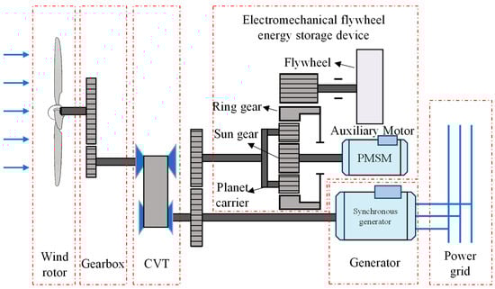
Figure 1.
Topology of the CVT and Flywheel-based Wind-Storage System.
In the electromechanical flywheel energy storage branch, a planetary gear mechanism is configured as a torque superposition and energy splitting device to construct a parallel electromechanical flywheel architecture. The planet carrier is rigidly connected to the main shaft of the synchronous generator, serving as the mechanical power confluence node of the main drivetrain. The sun gear is connected to the Auxiliary Permanent Magnet Synchronous Motor (Auxiliary PMSM), functioning as the active torque control terminal, while the floating ring gear is coupled to the high-inertia flywheel rotor via a gear transmission mechanism, acting as the energy storage and buffering terminal. Leveraging the three-port differential characteristics of the planetary gear train, this topology enables the flywheel branch to perform torque compensation and power exchange with the main drivetrain. This is achieved by applying control torque to the sun gear via the auxiliary motor, while the main shaft speed remains constrained by the grid frequency.
2.2. Kinematic Constraints and Dynamic Modeling of the Drivetrain
2.2.1. Kinematic Constraints for Source-Side Speed and Terminal Differential Regulation
To establish the physical foundation for the control strategy, it is essential to clarify the system’s kinematic constraints and dynamic transmission relationships. First, to ensure the direct grid connection of the synchronous generator, the CVT must strictly regulate the input-output speed ratio in real time to compensate for wind rotor speed fluctuations. This ensures that the planet carrier speed is dynamically maintained near the mechanical synchronous speed corresponding to the grid frequency, thereby establishing a mechanical decoupling mechanism between the source-side speed and the grid-side frequency. The kinematic constraint can be expressed as:
where , , and denote the rotational speeds of the planet carrier, synchronous generator, and wind rotor, respectively (rad/s); and represent the input-output speed ratios of the CVT and the gearbox, respectively; and is the mechanical synchronous speed corresponding to the grid frequency (rad/s).
Secondly, the electromechanical flywheel branch adheres to the Willis Theorem for planetary gear trains, with the kinematic equation governed by:
where and denote the rotational speeds of the sun gear and the ring gear (flywheel), respectively (rad/s); represents the characteristic parameter of the planetary gear mechanism; and is the gear ratio between the ring gear and the flywheel, defined as .
Since the main drivetrain dynamically maintains at the constant , the equation indicates a linear coupling between the flywheel speed and the auxiliary motor speed. Based on this constraint, regulating the auxiliary motor speed allows for linear control of the flywheel rotor’s charging and discharging states via differential coupling, all while ensuring the generator operates at a constant frequency.
2.2.2. Nonlinear Dynamic Modeling Considering Time-Varying Transmission Characteristics
To characterize the transient behavior during variable transmission ratio regulation, a multibody dynamic model encompassing the main shaft system and the flywheel branch is established. To focus on the macroscopic power flow characteristics, the drivetrain is modeled as a multi-body rigid system in this study; thus, torsional stiffness and damping effects are neglected in the dynamic formulation. Given the transient time-varying nature of the CVT ratio change, the angular acceleration of the CVT output shaft, , is influenced not only by the input shaft state but also exhibits nonlinear coupling with the rate of change in the speed ratio, :
where and represent the angular accelerations of the planet carrier and wind rotor, respectively (rad/s2); and denotes the time-varying rate of the CVT speed ratio (the time derivative of the speed ratio).
Consequently, the equivalent driving torque referred to the planet carrier side must account for the additional inertial term introduced by the rate of change in the speed ratio:
where and are the aerodynamic torque of the wind rotor and the equivalent driving torque referred to the planet carrier side, respectively (N·m); and represents the equivalent moment of inertia of the wind rotor and gearbox referred to the planet carrier side (kg·m2).
Simultaneously, the planet carrier main shaft system is subjected to the driving torque from the CVT, the electromagnetic resistance torque of the generator, and the coupling torque from the planetary gear train. The dynamic equilibrium equation is given by (Equation (5)):
where denotes the equivalent inertia of the planet carrier (kg·m2); and and represent the generator electromagnetic resistance torque and the coupling torque, respectively (N·m).
Furthermore, the energy interaction mechanism of the electromechanical flywheel depends on the dynamic equilibrium of the sun gear and the ring gear. To rigorously analyze the motion and interaction forces within the differential gear train, a force analysis of its internal components is performed, as illustrated in Figure 2.

Figure 2.
Dynamic force analysis of components in the planetary differential gear train.
Consequently, the integrated equations governing the torque and angular acceleration of the differential gear train components are derived as follows:
where is the number of planet gears; , , , denote the radii of the respective components (m); , , represent the transmission torques of the ring gear, sun gear, and planet carrier, respectively (N·m); , denote the corresponding moments of inertia (kg·m2); and is the mass of the planet gear (kg).
The aforementioned model elucidates the system’s energy coupling mechanism: by leveraging the differential characteristics of the planetary gear train, the inertial power flow of the flywheel rotor is precisely managed via auxiliary motor speed control. This allows for the dynamic reconstruction of the planet carrier coupling torque, , establishing the physical basis for the system’s “peak shaving and valley filling” capabilities.
2.3. Multi-Mode Energy Flow Mechanism Driven by Power Supply and Demand
Based on the dynamic model described above, the system transitions smoothly between multiple operational modes according to the instantaneous power supply and demand status of the source-grid interface, thereby maintaining dynamic power balance. When captured wind energy is excessive (), the system enters the energy surplus (charging) mode. The auxiliary motor drives the flywheel to accelerate, diverting the excess torque at the planet carrier and converting it into flywheel kinetic energy for physical storage. Conversely, under wind energy deficit conditions (), the system switches to the energy deficit (discharging) mode. The auxiliary motor speed is controlled to utilize the planetary differential action to force the flywheel to decelerate and release kinetic energy, compensating the torque on the main shaft via the ring gear to maintain stable generator output. During the power balance stage, the system operates in the power holding mode, where the flywheel performs only minor charging and discharging cycles to smooth the output power.
3. Adaptive Cooperative Control Strategy Based on Multi-Dimensional State Perception
To address the conflict between the stochastic nature of wind energy and the finite capacity of the electromechanical flywheel, single-dimensional control methods are no longer sufficient to meet system stability requirements under complex operating conditions. Consequently, this paper moves beyond traditional independent layered control approaches to construct a holistic coordinated control architecture that deeply integrates mechanical transmission, aerodynamic regulation, and electromechanical power distribution. This architecture is founded on source-side mechanical speed regulation, utilizes aerodynamic fuzzy logic as the energy boundary constraint, and employs adaptive power feasible region shaping on the electromechanical side as the core execution mechanism, aiming to optimize energy flow across the entire link.
3.1. Fuzzy Pitch Control Considering Energy Storage State Perception
At the source side of the mechanical transmission, the system leverages the speed ratio regulation characteristics of the CVT to dynamically stabilize the planet carrier (i.e., generator input shaft) speed at the grid synchronous frequency . This achieves a strong physical coupling between the generator rotor and the grid. Building on this mechanical decoupling, the control system fine-tunes the CVT ratio to alter the equivalent load impedance at the wind rotor side. This ensures the wind rotor speed tracks the optimal power curve in real-time, thereby achieving Maximum Power Point Tracking (MPPT). However, given the finite physical moment of inertia of the electromechanical flywheel, a pure MPPT strategy is prone to causing overcharging or deep discharging of the energy storage unit during continuous high winds or turbulent conditions.
To mitigate this, an Energy-Aware fuzzy logic controller is introduced on the aerodynamic side to establish a nonlinear mapping between the State of Energy (SOE) and pitch control behavior. Based on the flywheel SOE deviation and power capture deviation , the controller dynamically outputs a correction coefficient through fuzzy reasoning, with its mathematical model described as:
where represents the maximum captured power (MW), and denotes the rated power of the unit (MW).
In this strategy, the normalized universe of discourse for power capture deviation and SOE is defined as [0, 1], with the fuzzy subsets {VS (Very Small), MS (Medium Small), S (Small), B (Big), MB (Medium Big), VB (Very Big)}; The normalized universe of discourse for the compensation power coefficient β is [−0.2, 0.8], with the fuzzy subsets {ES (Extremely Small), VS (Very Small), MS (Medium Small), S (Small), M (Medium), B (Big), MB (Medium Big), VB (Very Big), EB (Extremely Big)}. The specific distributions of these membership functions are illustrated in Figure 3. The fuzzy control rules are presented in Table 1.
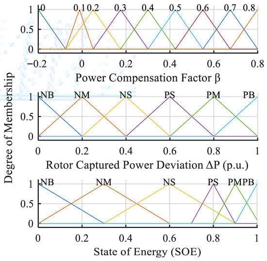
Figure 3.
Membership functions of the fuzzy controller variables.

Table 1.
Fuzzy control rule table.
Following defuzzification using the center of gravity method, the control law exhibits significant Sigmoidal-like dynamic characteristics, as shown in Figure 4. This nonlinear characteristic ensures that the SOE follows a “slow-fast-slow” smooth transition trend during regulation, achieving intelligent and flexible limiting of input mechanical energy while guaranteeing mechanical safety.
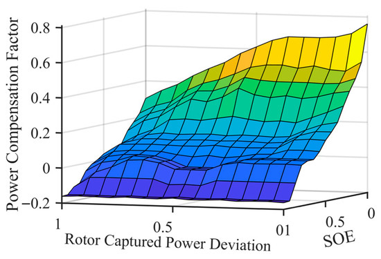
Figure 4.
Three-dimensional surface of energy-aware fuzzy controller.
This strategy embodies the control philosophy of “reverse compensation and asymmetric suppression”: when the SOE is in the high saturation zone, the controller outputs a negative gain to lower the upper limit of pitch power, forcing the blades to pitch early to suppress excess energy capture at the source. Conversely, in a low SOE state, short-term over-generation is permitted to replenish kinetic energy. This nonlinear regulation mechanism maximizes the system’s energy utilization efficiency while ensuring flywheel safety.
3.2. Target Power Synthesis Under Source-Grid-Storage Multi-Dimensional Synergy
Following the establishment of energy input boundaries at the source and aerodynamic sides, this section focuses on the target power synthesis mechanism on the electromechanical side. The core objective of the electromechanical control system is to compute the ideal target grid power for the synchronous generator based on current wind conditions, SOE, and generator operational status. The generation of this command deeply integrates the multidimensional requirements of steady-state smoothing and transient support, where the latter is realized through a virtual damping control mechanism based on speed feedback to effectively suppress bidirectional rotor oscillations. In terms of steady-state operation, to establish a dynamic balance between “smoothing grid fluctuations” and “maintaining flywheel kinetic energy,” the system employs a discretized first-order Low-Pass Filter (LPF) to shape the frequency domain of the random power captured by the wind rotor, filtering out high-frequency turbulence components to extract a stable power baseline. Simultaneously, a proportional Droop Control based on the deviation of the flywheel’s current State of Energy is introduced as an energy feedback correction term to prevent the SOE from deviating from the reference value for extended periods.
To address rotor speed fluctuations potentially triggered by grid voltage dips or sudden load changes, a Bidirectional Active Damping Control strategy based on speed feedback is further embedded. This module constructs a virtual strong damping channel: when the generator speed deviates from the synchronous speed , the damping term rapidly generates a reverse power correction command. This mechanism possesses bidirectional regulation characteristics: when the rotor accelerates (), a negative command is generated to force the auxiliary motor to absorb energy; conversely, when the rotor decelerates (), a positive command is generated to release flywheel kinetic energy. Physically, this simulates high moment of inertia characteristics, effectively suppressing bidirectional rotor oscillations. Letting the sampling time be , the filtering time constant be , be the filtering coefficient, be the droop gain, and be the damping gain, the synthesis logic for the generator target grid power at time is as follows:
The tuning of the key control parameters is based on the following principles:
- 1.
- Low-Pass Filter Time Constant (): Designed based on the bandwidth requirement to filter out high-frequency turbulence components (above 0.8 Hz) while retaining power command tracking capability.
- 2.
- Droop Gain (): Determined by the allowable energy buffer capacity of the flywheel, ensuring that a 20% deviation in SOE corresponds to a 10% power adjustment to prevent over-charging/discharging.
- 3.
- Active Damping Gain (): Tuned via parameter sensitivity analysis to achieve a critically damped response (). This setting ensures that the generator speed converges rapidly to the reference without exhibiting dangerous overshoot that could trigger overspeed protection mechanisms.
3.3. Power Constraint Strategy Based on Adaptive Tuning of the Power Feasible Region
Given the strict physical limits of flywheel speed and the necessity for the generator to possess short-term overload capability during transient faults, this paper further establishes a dual adaptive constraint mechanism based on SOE perception and speed transient perception. This mechanism models the power output feasible region as a piecewise function of multi-dimensional state variables, achieving a balance between system safety and transient performance by dynamically adjusting power boundaries. To ensure the smoothness of boundary adjustments, the algorithm first defines linear state transition factors and based on the degree to which the current energy storage state SOE deviates from the warning thresholds.
To balance the physical safety constraints of the flywheel speed with the generator’s short-term overload requirements during transient faults, this paper proposes an adaptive power constraint mechanism that fuses SOE perception and speed deviation perception. This mechanism models the synchronous generator’s grid-connected power feasible region as a piecewise function of multi-dimensional state variables. By dynamically shaping the power boundaries in real-time, it achieves an effective balance between operational safety and transient support performance.
Once the state transition factors are determined, the lower boundary of the power feasible region is shaped to avoid the risk of flywheel low-energy stall. When the flywheel SOE enters the low-charge warning zone , the transition factor is utilized to linearly contract the discharge power lower limit , making it transition smoothly from the steady-state lower limit to the limit value , thereby restricting excessive energy release from the flywheel:
Correspondingly, the setting of the upper power boundary is a composite process that integrates the needs for transient speed support and high-SOE dumping protection. First, a transient overload unblocking logic based on speed deviation perception is introduced to determine the power upper limit baseline . When the generator speed drop is detected to exceed the dead zone threshold , indicating that the grid urgently requires flywheel energy release to boost speed and support voltage, the control strategy actively relaxes the power upper limit baseline to the transient allowable overload value , thereby prioritizing the system’s transient stability:
Furthermore, to prevent flywheel overcharging under energy saturation conditions, the final power upper limit is synthesized in combination with the energy dumping protection logic under high SOE. If the flywheel SOE is in the high-level warning zone (), the transition factor is used to dynamically elevate the boundary from the preliminary baseline toward the maximum dumping power , allowing the generator to output more power to drain the accumulated energy in the flywheel. This hierarchical boundary design ensures that under both extreme conditions of urgent transient need and energy saturation, the system can break through conventional limits to achieve optimal energy throughput:
Integrating the aforementioned target power synthesis and adaptive boundary constraint modules, the final generator target grid power command , after safety boundary correction, is determined by the saturation limiter (Equation (14)):
In summary, the holistic coordinated control architecture constructed in this paper effectively resolves the contradiction between the stochastic nature of wind energy and the finite capacity of the flywheel through the deep coupling of multiple physical fields. This strategy organically fuses the frequency stability foundation established by source-side mechanical speed regulation, the energy defense boundary constructed by aerodynamic-side fuzzy logic, and the dynamic power regulation realized by electromechanical-side adaptive power feasible region shaping, forming a closed-loop collaborative system from the mechanical source to the electrical terminal. This full-chain energy flow optimization mechanism not only breaks the limitations of fragmentation in response speed and constraint management found in traditional layered controls but also maximizes the flywheel’s transient support potential while ensuring physical safety. This significantly enhances the dynamic adaptability and operational robustness of the hybrid wind storage system under complex conditions, laying a solid theoretical foundation for subsequent simulation verification.
4. Simulation Verification and Operational Characteristic Analysis
To validate the topological advantages of the proposed hybrid wind-storage system and the effectiveness of the multi-mode coordinated control strategy, a full-dimensional model encompassing aerodynamics, mechanical transmission, and electrical systems was constructed on the Simulink platform. The simulation target is configured as a 2 MW wind turbine, The key parameters are listed in Table 2.
Table 2.
Key parameters of the simulation system.
Furthermore, to realistically reflect the dynamic response characteristics and physical constraints of the CVT during actual speed regulation, this study eschews the ideal transient ratio model. Instead, a dynamic model incorporating actuator delay and rate limiting is established.
Letting the target speed ratio command of the CVT be and the actual speed ratio be , the dynamic process is described using a first-order inertial link to account for the response lag of the hydraulic actuator:
Constrained by the build-up speed of the CVT pulley clamping force and the mechanical structural strength, there exists a physical limit on the rate of change in the speed ratio. Consequently, the actual speed ratio dynamic response equation is modified as:
In this study, the time constant is set to = 0.2 s and the maximum rate of change is set to = 2.0/s, simulating the mechanical speed regulation hysteresis effect under realistic operating conditions.
To comprehensively evaluate the system’s adaptability across all operating conditions, three typical turbulent wind scenarios covering the cut-in to cut-out range were selected as inputs, as shown in Figure 5a: low (8 m/s, 14% turbulence intensity), medium (12 m/s, 20% turbulence intensity), and high (18 m/s, 20% turbulence intensity). The analysis is conducted across three dimensions: steady-state speed regulation, power smoothing efficiency, and transient fault ride-through capability.
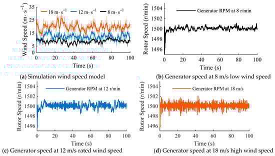
Figure 5.
Control accuracy of generator speed under different wind speeds.
4.1. Analysis of Speed Regulation Accuracy and Power Smoothing Characteristics
Based on the high-fidelity model, the steady-state operational indicators of the system under stochastic wind conditions were first analyzed. As illustrated in Figure 5b–d, the simulation results across the full wind speed range demonstrate that the differential speed regulation system exhibits exceptional speed rigidity. Statistical data indicate that even under severe conditions with an average wind speed of 18 m/s and 20% turbulence intensity, the generator input speed is effectively constrained within the extremely narrow range of [1495.75, 1502.05] r/min. Relative to the rated speed, the maximum positive peak error is merely 0.13%, the maximum negative peak error is contained within 0.28%, and the mean absolute error (MAE) over the entire time domain is as low as 0.02%. Notably, system performance at wind speeds of 8 m/s and 12 m/s surpasses that at 18 m/s. These results strongly validate the robustness of the “CVT source-side speed regulation and electromechanical flywheel terminal power stabilization” strategy in isolating mechanical disturbances, ensuring strict frequency stability for the directly connected synchronous generator.
Regarding power smoothing characteristics, the system achieves real-time exchange and dynamic modulation of stochastic wind energy via active torque control of the electromechanical flywheel branch. As shown in Figure 6, influenced by the coupling of turbulence shear effects, the raw mechanical power captured by the wind rotor exhibits intense wide-frequency oscillations, with a peak-to-valley fluctuation range reaching 2.71 MW. However, through the smoothing action of the electromechanical flywheel system, the grid-connected active power effectively eliminates large-amplitude instantaneous pulsations, demonstrating a significant smoothing trend. Test results indicate that the output power fluctuation range is compressed to 1.42 MW, a reduction of 47.60%, while the power standard deviation is significantly reduced from 0.40 MW to 0.27 MW, a decrease of 32.58%.These results physically validate that the proposed topology, leveraging the rapid regulation capability of the electromechanical branch, possesses superior “peak shaving and valley filling” capabilities and high-frequency disturbance suppression performance. This high-quality power injection effectively alleviates the frequency regulation pressure on the grid, thereby reducing the system’s demand for spinning reserve capacity
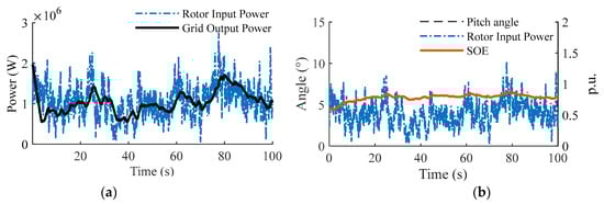
Figure 6.
Power smoothing characteristics and system response under random wind conditions. (a) Comparison between rotor captured power and grid active power. (b) Dynamic response of pitch angle and flywheel SOE.
Furthermore, the energy throughput requirement of the auxiliary motor is significantly superior to that of traditional mainstream power electronic solutions. As shown in Figure 7, under severe turbulence at 18 m/s, the power splitting capability of the planetary gear train ensures that the majority of power fluctuations are absorbed by the flywheel. Consequently, the operating Root Mean Square (RMS) power of the auxiliary motor is only 67.2 kW, with the steady-state power ratio controlled within 15%.Compared to the approximate 30% slip power capacity of typical Doubly Fed Induction Generator (DFIG) units and the 100% capacity of full-power converters in Permanent Magnet Synchronous Generator (PMSG) units, the proposed topology reduces the installed capacity of power electronic devices by approximately 50% and 85%, respectively. This distinct characteristic of “leveraging large inertia with small capacity” not only significantly reduces the converter’s installed capacity but also effectively mitigates the high switching losses associated with full-power conversion.
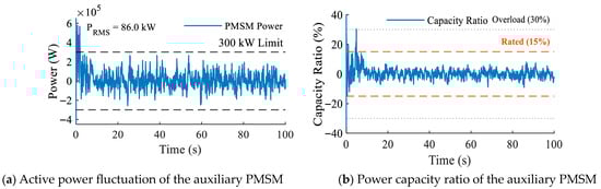
Figure 7.
Power profile of the auxiliary motor.
To further analyze the efficacy of the control strategy under complex conditions, a dynamic process involving sudden wind speed drops and strong gust ramps was selected as the test scenario (as shown in Figure 8). This allowed for a full-time domain verification of the “target power synthesis” and “power constraint based on power feasible region shaping” mechanisms. First, as shown in Figure 8a, during the low wind speed and energy deficit interval (t = 0~60 s), although the pitch angle remains at 0°, the output power does not oscillate with the same amplitude as the wind speed. Notably, during the power trough at t = 30~50 s, the grid connection curve exhibits a distinct smooth transition. This indicates that the electromechanical control system successfully executed the frequency domain shaping based on the discretized first-order LPF and the bidirectional active damping algorithm, actively releasing flywheel kinetic energy to fill the power gap and maintain output stability.
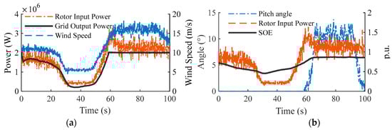
Figure 8.
Full-time domain dynamic response characteristics of the system under gust disturbance. (a) Wind speed excitation and active power regulation curves. (b) Coordinated response of pitch angle and flywheel SOE.
Subsequently, when the system encounters a gust impact and enters the rated load zone (t > 60 s), the grid power rises rapidly and is precisely clamped at 2.0 MW. Significantly, even during the strong gust phase with violent wind speed fluctuations, the output power remains highly smooth and constant without significant overshoot or oscillation. At this point, the flywheel SOE and pitch angle in Figure 8b demonstrate high synergy: as the SOE approaches the high-level warning threshold, the asymmetric feasible region shaping mechanism is activated. This forces the aerodynamic subsystem to intervene deeply, rapidly increasing the pitch angle to implement “source-side power curtailment,” thereby eliminating residual power fluctuations in coordination with the fine-tuning of the electromechanical flywheel while cutting off excess wind energy. Thanks to this multi-dimensional synergy from active compensation in low wind zones to curtailment in high wind zones, the flywheel SOE is strictly constrained within the safety interval, achieving energy boundary management and superior power smoothing across all operating conditions.
Finally, the analysis of grid-connected power quality reveals that this topology possesses inherent harmonic suppression advantages. Figure 9 presents the time-domain waveform of the generator stator current, exhibiting extremely high sinusoidal fidelity with no obvious waveform distortion. Further spectrum analysis indicates that the Total Harmonic Distortion (THD) is only 0.81%, with the 5th, 7th, 11th, and 13th harmonics at 0.17%, 0.12%, 0.08%, and 0.06%, respectively. These levels are extremely low, far below the typical 2%~5% values of DFIG and PMSG wind turbines [30,31]. This superior characteristic is attributed to the “mechanical decoupling–electrical direct connection” architecture of the drivetrain, which fundamentally eliminates the high-frequency Pulse Width Modulation (PWM) switching harmonics associated with power electronic converters in traditional DFIG or direct-drive units. Consequently, as a pure rotating mechanical power source, the system directly satisfies stringent grid interconnection standards without the need for complex passive or active filtering devices, demonstrating exceptional grid friendliness.
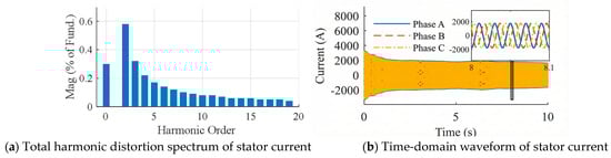
Figure 9.
Analysis of steady-state grid-connected power quality.
4.2. Evaluation of Low Voltage Ride-Through (LVRT) Capability Under Grid Voltage Dips
To further highlight the superiority of the proposed topology in handling grid faults, a three-phase deep voltage dip at the grid connection point (a dip depth of 0.6 p.u. lasting for 500 ms) was simulated. The dynamic response of the proposed system was compared with that of a DFIG unit under identical conditions. At the instant of the fault, the two types of units exhibited distinct transient characteristics. As shown in Figure 10a, when the grid voltage dip occurs, the electromagnetic torque of the traditional DFIG unit drops precipitously. Consequently, the rotor severely overspeeds under the influence of the residual mechanical torque, with the peak speed soaring to 1.07 p.u., posing a significant risk of runaway overspeed and grid disconnection. In contrast, the proposed system benefits from the intervention of the “speed-aware active damping” strategy. The auxiliary motor responds rapidly, diverting excess mechanical energy to the electromechanical flywheel. This strictly confines generator speed fluctuations to the range of 0.98–1.02 p.u., demonstrating strong “equivalent inertia” characteristics.
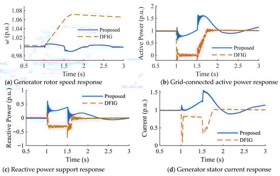
Figure 10.
Comparison of fault ride-through characteristics during grid voltage dip.
Regarding grid support, as shown in Figure 10b,c, the active and reactive power of the DFIG exhibit violent oscillations and drops during the initial fault stage, failing to provide effective support to the grid. Figure 10d illustrates the stator current response. Further examination reveals that the DFIG, constrained by rotor-side protection strategies (such as Crowbar activation or converter blocking), experiences a significant collapse in output current during the fault, rendering it unable to contribute the necessary short-circuit current. Conversely, the proposed system demonstrates superior electromechanical transient regulation capabilities: although its active power decreases due to the voltage dip, the recovery process is much smoother. More critically, the synchronous generator excitation system is able to rapidly and continuously inject approximately 0.5 p.u. of reactive power. Simultaneously, the stator current responds rapidly under strong excitation, maintaining a high level above 1.2 p.u. This continuous and controlled fault current injection not only enhances voltage support but also provides the necessary short-circuit capacity to ensure the correct operation of grid relay protection devices.
Observation of internal control variables reveals that at the instant of the voltage dip, the speed perception logic successfully triggered the “transient unblocking” of the power upper limit. This instantaneously relaxed the power feasible region boundary, ensuring the auxiliary motor could absorb surplus rotor energy without restriction. Unlike conventional control strategies that often lead to generator overspeed protection tripping due to delayed power adjustment, this proactive energy diversion strategy ensures continuous grid connection during severe faults. This decoupled response mechanism of “mechanical-side energy absorption for speed stabilization and electrical-side reactive support” is significantly superior to that of traditional units. It effectively supports the rapid recovery of the voltage at the point of common coupling (PCC), thereby substantially enhancing the transient stability of the power system.
Furthermore, to verify the operational robustness of the proposed control strategy against parameter uncertainties—a critical concern raised for practical implementation—a sensitivity analysis was conducted on the active damping gain . As illustrated in Figure 11, the system’s dynamic response under the grid voltage dip was evaluated with varying from 0 (No Control) to 1.5 times the nominal value (). The results indicate that in the absence of damping control (), the generator speed exhibits severe oscillations with a peak exceeding 1.13 p.u., posing a high risk of triggering overspeed protection. Conversely, upon activating the control, the oscillations are effectively suppressed. Notably, the system demonstrates strong robustness: even when deviates by 50% from the nominal design, the rotor speed converges rapidly to the synchronous speed without divergence. The nominal setting () achieves an optimal critically damped response, balancing recovery speed and overshoot suppression.
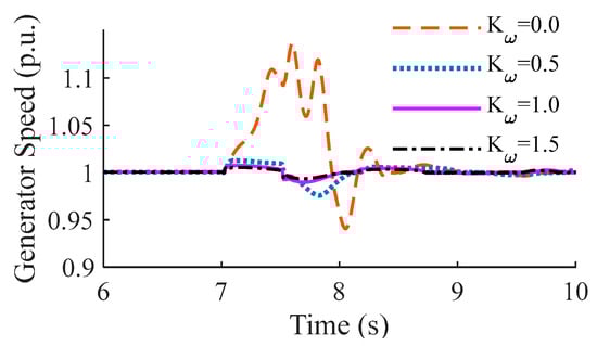
Figure 11.
Sensitivity analysis of generator speed dynamic response under grid voltage dip with varying active damping gains. The gain values are normalized relative to the nominal tuning value (). The comparison validates that the system maintains stability across a wide parameter range.
5. Discussion on Practical Implementation and Performance Comparison
The topology proposed in this study demonstrates significant superiority in theory and simulation. However, to facilitate the transition from theoretical research to industrial application, it is essential to objectively discuss the feasibility of megawatt-scale mechanical transmission, the trade-off in reliability, and to conduct a quantitative comprehensive comparison with existing mainstream wind power technologies.
5.1. Feasibility of Megawatt-Scale CVT
Scaling friction-based CVTs to the 2 MW level faces physical constraints regarding heat dissipation and tensile strength, though the dynamic model established here explicitly incorporates critical nonlinear constraints like response time constants and ratio rate limiters to capture necessary transient behaviors. For industrial implementation, mature power-split solutions such as Hydro-Mechanical Transmissions (HMT) or Speed-Regulating Differential Planetary Gearboxes serve as viable hardware carriers [32,33,34]. Unlike pure friction drives, these topologies utilize a planetary gear train to shunt the majority of power through a high-efficiency mechanical path. While such differential systems typically introduce losses of 10–15%—exceeding the 2–3% loss of the removed back-to-back converter—this penalty is partially mitigated by the elimination of active cooling systems for IGBTs and the reduction in harmonic-induced iron losses. Even if peak efficiency is slightly compromised, this trade-off is scientifically justified by the system’s unique capability to provide native physical inertia and enhance LVRT performance, and the core control principle proposed in this paper remains effective when transplanted onto these robust platforms to address power scaling bottlenecks.
5.2. Comparative Analysis of Mechanical and Electrical Reliability
Regarding system maintenance, it must be admitted that the proposed mechanical-hydraulic system introduces requirements for lubrication, sealing, and wear management. However, from the perspective of system robustness, this design exchanges full-power converters for unique reliability advantages. In traditional wind turbines (especially direct-drive PMSG units), IGBT modules and DC-link capacitors are the components most sensitive to thermal cycling and environmental stress, often being the primary causes of sudden shutdowns. In contrast, mechanical wear typically exhibits progressive degradation, which can be effectively predicted and planned for through vibration monitoring or oil analysis. By reducing the converter capacity requirement to approximately 15% of the rated power (used only for the auxiliary motor) and removing fragile power electronic devices from the main power flow path, the system greatly reduces the risk of high-frequency harmonic pollution and thermal runaway, offering potential long-term operational advantages in difficult-to-maintain environments such as remote or offshore locations.
5.3. Comprehensive Performance Comparison
To further clarify the positioning of this system relative to existing mainstream technologies, Table 3 provides a horizontal comparison between the CVT-flywheel system proposed in this study and Doubly Fed Induction Generators (DFIGs) as well as Permanent Magnet Synchronous Generators (PMSGs) across four dimensions: inertia support mechanism, converter capacity requirement, harmonic characteristics, and fault ride-through capability.
Table 3.
Comparative analysis between the proposed system and traditional wind turbines.
As illustrated in Table 3, while the proposed system involves increased mechanical complexity, its superiority in reducing reliance on power converters (an ~85% reduction compared to PMSG) and ensuring pristine power quality is unmatched by traditional models. These attributes position the proposed topology as a highly competitive and ‘grid-friendly’ alternative for future power systems characterized by high renewable energy penetration.
6. Conclusions
Addressing the inertia deficiency in large-capacity converter-based wind turbines and the limitations of existing mechanical speed regulation technologies regarding power smoothing, this paper constructs a novel hybrid wind energy storage system integrating a Continuously Variable Transmission (CVT) and an electromechanical flywheel. Through an in-depth analysis of the energy transmission mechanism and full-dimensional numerical modeling, combined with an adaptive multi-mode coordinated control strategy based on power feasible region shaping, the system was comprehensively validated via simulation across three dimensions: steady-state speed regulation accuracy, power smoothing efficiency, and transient fault ride-through capability. The main conclusions are as follows:
- The proposed cascaded topology of “CVT source-side speed regulation and electromechanical flywheel terminal power stabilization” achieves physical-layer decoupling of mechanical transmission and electrical energy conversion via the planetary differential mechanism. Simulation results demonstrate that under severe turbulence, the synchronous generator’s input speed steady-state error is confined within 0.28%, with a full-time domain mean error of only 0.02%. The auxiliary motor operates with an RMS power of just 67.2 kW, keeping the steady-state power ratio within 15%. This verifies the architecture’s superior capability for constant frequency grid connection and speed rigidity retention without requiring large-capacity converters.
- The collaborative control architecture, which fuses the aerodynamic fuzzy boundary with electromechanical-side power feasible region shaping, effectively resolves the conflict between wind stochasticity and the flywheel’s finite capacity. In multi-scenario testing, the electromechanical flywheel system’s active energy exchange reduced the grid power fluctuation range by 47.60% and the standard deviation by 32.58%. Furthermore, the stator current Total Harmonic Distortion (THD) was only 0.81%, far lower than that of traditional converter-based units, highlighting the system’s significant advantages in enhancing power quality and achieving “peak shaving and valley filling.”
- Under extreme conditions of deep grid voltage dips, the fault ride-through mechanism based on active damping and energy diversion significantly enhances the system’s transient stability. The speed-aware transient unblocking strategy successfully diverts excess mechanical energy to the flywheel rotor, limiting generator speed fluctuations to within 0.5% and completely eliminating the risk of runaway overspeed and grid disconnection associated with traditional units. Simultaneously, in coordination with the strong excitation of the excitation system, the system achieves the stable injection of 0.5 p.u. reactive power and sustained short-circuit current. This decoupled response mode of “mechanical-side energy absorption for speed stabilization and electrical-side reactive support” provides a novel technical pathway for the safe and stable operation of power systems with high renewable energy penetration.
In summary, the hybrid wind-storage topology proposed in this paper theoretically alleviates the contradiction between “constant frequency” and “stable power” inherent in traditional mechanical transmission technologies. It preliminarily validates the advantages of this solution in reducing the proportion of electrical equipment and enhancing grid friendliness, providing a solid theoretical foundation and practical basis for the design and optimization of future wind power grid integration equipment. Future work will focus on the hardware implementation based on mature hydro-mechanical transmission (HMT) platforms to further validate the system’s scalability and reliability in megawatt-level industrial applications.
Author Contributions
Conceptualization, S.-K.L.; Data curation, D.O.; Formal analysis, T.L.; Investigation, D.O.; Methodology, T.L. and Z.Q.; Project administration, Z.Q.; Software, Y.-T.W.; Supervision, S.-K.L.; Validation, Y.-T.W.; Writing—original draft, T.L.; Writing—review and editing, S.-K.L. and Z.Q. All authors have read and agreed to the published version of the manuscript.
Funding
This research was supported by the Shandong Provincial Natural Science Foundation under Grants ZR2024ME088, ZR2025QC573 and ZR2024ME003, the NRF-NSFC Bilateral Collaboration Program (52411540234), the National Research Foundation of Korea (NRF) grant funded by the Korea government (MSIT) (No. RS-2019-NR040067), and the Material and Components Technology R&D Project of the Korea Ministry of Trade, Industry and Energy (Grant No: RS-2024-00434150).
Data Availability Statement
The original contributions presented in this study are included in the article. Further inquiries can be directed to the corresponding author.
Conflicts of Interest
Author Yu-Ting Wu was employed by the company Zhejiang Shuanghuan Driveline Co., Ltd. The remaining authors declare that the research was conducted in the absence of any commercial or financial relationships that could be construed as a potential conflict of interest.
References
- Roga, S.; Bardhan, S.; Kumar, Y.; Dubey, S.K. Recent technology and challenges of wind energy generation: A review. Sustain. Energy Technol. 2022, 52, 102239. [Google Scholar] [CrossRef]
- Ahmed, M.; Mirsaeidi, S.; Koondhar, M.A.; Karami, N.; Tag-Eldin, E.M.; Ghamry, N.A.; El-Sehiemy, R.A.; Alaas, Z.M.; Mahariq, I.; Sharaf, A.M. Mitigating Uncertainty Problems of Renewable Energy Resources Through Efficient Integration of Hybrid Solar PV/Wind Systems Into Power Networks. IEEE Access 2024, 12, 30311–30328. [Google Scholar] [CrossRef]
- Catalán, P.; Wang, Y.B.; Arza, J.; Chen, Z. A Comprehensive Overview of Power Converter Applied in High-Power Wind Turbine: Key Challenges and Potential Solutions. IEEE Trans. Power Electron. 2023, 38, 6169–6195. [Google Scholar] [CrossRef]
- Cakiroglu, C.; Demir, S.; Ozdemir, M.H.; Aylak, B.L.; Sariisik, G.; Abualigah, L. Data-driven interpretable ensemble learning methods for the prediction of wind turbine power incorporating SHAP analysis. Expert Syst. Appl. 2024, 237, 121464. [Google Scholar] [CrossRef]
- Budanko, M.; Guzovic, Z. Design Methodology and Economic Impact of Small-Scale HAWT Systems for Urban Distributed Energy Generation. Machines 2024, 12, 886. [Google Scholar] [CrossRef]
- Abdelsattar, M.; Ismeil, M.A.; Menoufi, K.; Abdelmoety, A.; Emad-Eldeen, A. Evaluating Machine Learning and Deep Learning models for predicting Wind Turbine power output from environmental factors. PLoS ONE 2025, 20, e0317619. [Google Scholar] [CrossRef]
- Patel, K.N.; Patel, N.A.; Patel, J.; Sarda, J.; Sain, M. Enhanced Voltage Stability and Fault Ride-Through Capability in Wind Energy Systems Using FACTS Device Integration. Machines 2025, 13, 805. [Google Scholar] [CrossRef]
- Wang, P.; Guo, J.; Cheng, F.J.; Gu, Y.F.; Yuan, F.; Zhang, F.Q. A MPC-based load frequency control considering wind power intelligent forecasting. Renew. Energy 2025, 244, 122636. [Google Scholar] [CrossRef]
- Chen, H.; El-Refaie, A.; Zuo, Y.F.; Cai, S.; Tang, J.F.; Liu, Y.J.; Lee, C. A Permanent Magnet Brushless Doubly Fed Electric Machine for Variable-Speed Constant-Frequency Wind Turbines. IEEE Trans. Ind. Electron. 2023, 70, 6663–6674. [Google Scholar] [CrossRef]
- Nasim, F.; Khatoon, S.; Nasiruddin, I.; Shahid, M.; Urooj, S.; Bilal, B. Support-Vector-Regression-Based Intelligent Control Strategy for DFIG Wind Turbine Systems. Machines 2025, 13, 687. [Google Scholar]
- Deng, Z.W.; Xu, C.; Huo, Z.H.; Han, X.X.; Xue, F.F. Sliding Mode Based Load Frequency Control and Power Smoothing of Power Systems with Wind and BESS Penetration. Machines 2022, 10, 1225. [Google Scholar] [CrossRef]
- Blaabjerg, F.; Yang, Y.H.; Kim, K.A.; Rodriguez, J. Power Electronics Technology for Large-Scale Renewable Energy Generation. Proc. IEEE 2023, 111, 335–355. [Google Scholar] [CrossRef]
- Pathak, P.K.; Yadav, A.K.; Kamwa, I. Resilient Ratio Control Assisted Virtual Inertia for Frequency Regulation of Hybrid Power System Under DoS Attack and Communication Delay. IEEE Trans. Ind. Appl. 2025, 61, 2721–2730. [Google Scholar] [CrossRef]
- Talani, R.A.; Kaloi, G.S.; Ali, A.; Bijarani, M.A.; Abbas, G.; Hatatah, M.; Mercorelli, P.; Touti, E. Dynamic Performance Analysis and Fault Ride-Through Enhancement by a Modified Fault Current Protection Scheme of a Grid-Connected Doubly Fed Induction Generator. Machines 2025, 13, 110. [Google Scholar] [CrossRef]
- Jiang, M.; Niu, S.; Chuen Chan, C. A High-Order-Harmonic Compound-Rotor Based Brushless Doubly-Fed Machine for Variable Speed Constant Frequency Wind Power Generation. IEEE J. Emerg. Sel. Top. Power Electron. 2025, 13, 1492–1502. [Google Scholar] [CrossRef]
- Zhang, Y.S.; Yuan, C.Y.; Du, X.Y.; Chen, T.; Hu, Q.R.; Wang, Z.; Lu, J.Z. Capacity configuration of hybrid energy storage system for ocean renewables. J. Energy Storage 2025, 116, 116090. [Google Scholar] [CrossRef]
- Tome-Amador, D.; Varela-Aguilera, C.; Rivera-López, D.A.; Muñoz Tabora, J. Application of Battery and Flywheel Energy Storage Systems for Frequency Regulation in the Honduran Power Grid. Energies 2025, 18, 6287. [Google Scholar] [CrossRef]
- Zhang, Y.; Yu, Y.; Zhang, Y.; Chen, B.; Liu, Z. Frequency Regulation Performance of a Wind–Energy Storage Hybrid System During Turbine Shutdown Due to Extreme Wind. Processes 2025, 13, 3383. [Google Scholar] [CrossRef]
- Ji, W.M.; Hong, F.; Zhao, Y.Z.; Liang, L.; Du, H.; Hao, J.H.; Fang, F.; Liu, J.Z. Applications of flywheel energy storage system on load frequency regulation combined with various power generations: A review. Renew. Energ. 2024, 223, 119975. [Google Scholar] [CrossRef]
- Duan, J.D.; Ni, H.; Tao, J.X.; Li, Z.F.; Zhang, Y.; Wang, J.H. Adaptive primary frequency regulation method based on energy perspective for integrated unit-level wind storage systems. Int. J. Electr. Power Energy Syst. 2025, 169, 110822. [Google Scholar] [CrossRef]
- Yan, K.F.; Li, G.Q.; Zhang, R.F.; Xu, Y.; Jiang, T.; Li, X. Frequency Control and Optimal Operation of Low-Inertia Power Systems with HVDC and Renewable Energy: A Review. IEEE Trans. Power Syst. 2024, 39, 4279–4295. [Google Scholar]
- Boyle, J.; Littler, T.; Foley, A.M. Coordination of synthetic inertia from wind turbines and battery energy storage systems to mitigate the impact of the synthetic inertia speed-recovery period. Renew. Energy 2024, 223, 120037. [Google Scholar] [CrossRef]
- Dai, F.Q.; Lin, Y.G.; Gu, Y.J.; Liu, H.W.; Chen, W.T.; Zhao, X.C. Design and Characteristic Analysis of Reflux Type Mechanical Hydraulic Hybrid Transmission for Wind Turbines. Wind. Energy 2025, 28, e70036. [Google Scholar] [CrossRef]
- Yin, W.L.; Liu, L.; Zhang, W.H.; Li, M.; Guo, Y.G. Performance Improving of Wind Power Generation Systems Through Parameter Optimization and Dynamic Analysis of the Speed-Regulating Differential Transmission. J. Energy Resour. Technol. 2023, 145, 121302. [Google Scholar] [CrossRef]
- Li, Y.; Cui, J.; Li, H.; Zhao, B. Control strategy of the novel stator free speed regulating wind turbine generation system. PLoS ONE 2024, 19, e314226. [Google Scholar] [CrossRef]
- Esquivel-Puentes, H.A.; Vacca, A.; Pulletikurthi, V.; Doosttalab, A.; Garcia-Bravo, J.; Warsinger, D.M.; Chamorro, L.P.; Castillo, L. On the design and power output response of hydraulic wind turbines. Energy Convers. Manag. 2023, 293, 117425. [Google Scholar] [CrossRef]
- Gerber, R.; Kamper, M. Stability Analysis of Grid-Strengthening Geared Direct Grid-Connected Dual-Speed Slip-Synchronous Wind Turbines. IEEE Open J. Ind. Appl. 2025, 7, 3–23. [Google Scholar]
- Yin, X.X.; Jiang, Z.S. A novel continuously variable-speed offshore wind turbine with magnetorheological transmission for optimal power extraction. Energy Source Part A 2023, 45, 6869–6884. [Google Scholar]
- Lin, J.; Yang, X.; Niu, S.; Yu, H.; Zhong, J.; Jian, L. Inflatable Savonius wind turbine with rapid deployment and retrieval capability: Structure design and performance investigation. Energy Convers. Manag. 2024, 310, 118480. [Google Scholar] [CrossRef]
- Jiang, Z.H.; Zhang, J.B. Machine-side Harmonic Suppression Strategy for Direct Driven Five-phase PMSG of Wind Power Generation System. Adv. Electr. Comput. Eng. 2024, 24, 85–92. [Google Scholar]
- Sachs, C.; Allgeier, J.; Stamer, F.; Neuburger, M. A Comprehensive Review of Modulation-Induced Motor Losses: Assessing the Impact of Voltage Source Inverters. IEEE Access 2025, 13, 180069–180090. [Google Scholar] [CrossRef]
- Wang, Z.W.; Yin, W.L.; Liu, L.; Wang, Y.; Zhang, C.S.; Rui, X.M. Fractional-order Sliding Mode Control of Hybrid Drive Wind Turbine for Improving Low-voltage Ride-through Capacity. J. Mod. Power Syst. Clean Energy 2023, 11, 1427–1436. [Google Scholar] [CrossRef]
- Yin, W.; Liu, L.; Wang, Y.; Wang, Z.; Li, J. Optimal allocation and energy management of a wind–hydrogen generation system equipped with the speed regulating differential mechanism. J. Renew. Sustain. Energy 2023, 15, 023302. [Google Scholar] [CrossRef]
- Mantriota, G. Power split transmissions for wind energy systems. Mech. Mach. Theory 2017, 117, 160–174. [Google Scholar] [CrossRef]
Disclaimer/Publisher’s Note: The statements, opinions and data contained in all publications are solely those of the individual author(s) and contributor(s) and not of MDPI and/or the editor(s). MDPI and/or the editor(s) disclaim responsibility for any injury to people or property resulting from any ideas, methods, instructions or products referred to in the content. |
© 2026 by the authors. Licensee MDPI, Basel, Switzerland. This article is an open access article distributed under the terms and conditions of the Creative Commons Attribution (CC BY) license.