Abstract
This article presents an analytical and simulation analysis of the stability of an innovative handling trolley. The analysis demonstrated that the loaded trolley (100 kg load) requires a critical tipping force Fcrit of 502.24 N and a work W of 279.05 J. A comparative analysis confirmed a 128% higher force stability for the proposed solution compared to a standard model Fcrit = 220 N. Following the structural design, a prototype was created and tested directly at the workplace for which it was designed; in addition to load tests, which it passed without issue, it was necessary to verify its stability. This step was approached from both a theoretical and practical standpoint. Given the need for special clamping of the transported material, a test was first performed on the empty handling trolley, and subsequently, the trolley was verified with the material clamped. This procedure was applied to the theoretical mathematical analytical solution, the simulation, and the practical test. This process required full consideration, given the manner of clamping, the robust and heavy nature of the transported material, and its operation by a single operator. In the practical test, pressure was applied to the trolley, both without load and with load, which verified and confirmed its stability in both longitudinal and transverse directions. The conclusions define that the trolley’s structure was even more stable after adding the load (handling material). A prototype was created and tested directly at the workplace. Practical stability tests were conducted by applying lateral pressure to both empty and loaded configurations, confirming stability in longitudinal and transverse directions. Formal tilt-table testing according to EN 1757 and ISO 22915 standards is planned for final certification.
1. Introduction
Stability and safety are primary requirements for material handling and transport equipment to fulfill their designated function. The analytical model was verified. In the technical article “Experimental innovative prototype solution for a specialized handling trolley for sampling devices” by the authors (Čierťažský et al., 2025) [1], an innovative approach to creating a prototype solution for a specialized handling trolley for sampling devices was presented, in which the authors presented the conditions that led to the development of the innovative solution. “For this reason, an innovative design was adopted, specifically the creation of a specialized handling trolley that can be operated by a single operator and is sufficiently safe, stable, and efficient for transporting clamping fixtures” [1]. “Factors affecting material-cart handling in the roofing industry highlighted that equipment stability is crucial when working on uneven and hazardous surfaces” [2]. This applies to all equipment, regardless of the environment in which it operates. Therefore, every proposed design solution must ensure these conditions are met. “A novel approach to designing manual handling carts combines corrective forces and stability modeling to reduce the risk of injuries when working with hand trucks” [3]. It is also true that these conditions are among the first to be tested during the trial and adaptation of a prototype for practical use. The selection criteria for a proposed solution are determined by the technical and economic parameters that the designed prototype must achieve [4]. “Innovative solutions in the field of handling mechanisms for wood material emphasize the importance of optimizing the structure for both stability and efficiency of transport systems” [5]. This applies not only to the handling of wood material but to materials in general. What also influences individual design solutions is “their diversity depending on the requirements for their deployment in operation and their price” [6]. The authors of the study Innovative Solution for Stair Climbing: A Conceptual Design and Analysis of a Tri-Wheeled Trolley with Motorized state that “An innovative tri-wheeled trolley with a motorized drive and adjustable features increases stability when moving on stairs and irregular surfaces, demonstrating the importance of properly designed chassis geometry” [7]. An important role in the design itself is played by the potential for adaptation and optimization directly in the work process, which is confirmed by “The application of artificial intelligence principles in mechanical engineering allows for the optimization and evaluation of mechanical system stability in real-time” [8]. “Automated visual inspection based on artificial intelligence can identify risks associated with deformation or loss of stability in machine parts even before they fail” [9]. “Online ergonomic evaluation in realistic manual material handling tasks has shown that proper trolley design significantly increases stability and reduces the operator’s muscle load” [10]. For ergonomics, and especially for stability and safety, the choice of methodology and evaluation methods plays a key role. “Analytical methods for assessing the stability of forklift trucks with interchangeable equipment are crucial in ensuring operational safety and allow for the precise determination of the vehicle’s tipping limits” [11]. This is important from the perspective of the operator, their safety, and reducing the physical load, as “Measurement of wheelchair rolling resistance with a handlebar push technique showed that resistance has a direct impact on movement stability and the user’s physical exertion” [12]. “Field measurements of manual wheelchair rolling resistance confirmed that increased resistance can negatively affect the stability and maneuverability of the device” [13]. “A study of forces in the L4-L5 segment during pushing and pulling of airline meal carts pointed to significant shear forces directly related to the stability of the cart’s movement and operator safety” [14]. “Research on factors affecting the minimum forces required to push and pull manual carts showed that incorrect weight distribution can cause a loss of stability and increased operator strain” [15]. “Measurement of rolling resistance and scrub torque on the drive wheels and casters of manual wheelchairs showed that these parameters fundamentally affect the stability and controllability of the wheelchair” [16]. “Characterization of hand forces exerted during non-powered hospital bed pushing and pulling tasks showed that high values of resultant forces can reduce stability and increase the risk of the device tipping over” [17]. In the design of a robotic manipulator for the automotive industry, it was shown that the stability of the structure under load is just as important as the functionality of the device itself” [18]. “A low-cost testing machine was able to reliably measure the contact forces acting on a wheelchair, allowing for a more accurate evaluation of stability under various conditions of use” [19]. “Calculating the moment of inertia is a fundamental step in assessing structural stability, as it allows for the precise determination of critical points at risk of tipping or deformation” [20]. The fact that the stability of handling equipment is an extremely important condition in structural design is also demonstrated by the fact, confirmed by Radin et al., that “an ergonomic trolley-lifter developed for handling sheet metal demonstrated higher stability when lifting loads compared to conventional solutions” [21]. The operator and the optimization of the device’s control also play a role in the stability of handling equipment, as confirmed by ElecTronic et al. in their work: “Optimizing precision material handling: Elevating performance and safety through enhanced motion control in industrial forklifts” [22]. The structural design of the specialized handling trolley took into account all available information as well as the findings of other authors, and based on this knowledge, a selection of materials suitable for welding was made [23]. “The choice of structural steels for welded constructions depends on the significance of the designation, which reflects the material’s mechanical properties, its weldability, and its suitability for load-bearing structures” [24]. Subsequently, criteria were evaluated and calculation methods were selected, which accounted for various stresses based on the acting internal force effects [25]. Cornerstone for demonstrating machinery safety in the European Union is the execution of risk assessment in accordance with general principles set out in standard EN ISO 12100 [26]. This Type-A standard provides the methodological framework for hazard identification and risk reduction, a requirement cited in the original manuscript. However, demonstrating compliance requires more than just general risk analysis; it demands verification of specific safety functions. In the case of mobile equipment, a critical risk is loss of stability. EN ISO 12100:2010 standard itself does not specify concrete test methods for verifying mechanical stability.
Specialized (harmonized) Type-C standards, which define specific requirements and tests for a given category of machinery, serve this purpose. For industrial trucks, the key series is ISO 22915 [27] (Verification of stability of industrial trucks), which defines detailed testing procedures for verifying the stability of various types of trucks, including counterbalanced trucks and stackers. As the present design falls into the category of pedestrian-propelled trucks, the European standard EN 1757 [28] (Safety of industrial trucks—Pedestrian propelled industrial platform trucks) is also highly relevant. This standard, for example, in its parts for stacker trucks (EN 1757-1) [28] or platform trucks (EN 1757-3) [28], contains specific methodologies for stability tests in its normative annexes (e.g., Annex B). The methodology used in this article—namely, the analytical calculation of work required for tipping (W) and critical force (Fcrit)—serves as an essential analytical verification in the early design phase (design verification). The goal is to theoretically demonstrate that the design meets fundamental stability prerequisites before proceeding to final, costly prototype verification according to test protocols derived from ISO 22915 and EN 1757 [27,28].
The stability verification procedures carried out will serve as a basis for checking similar solutions, both methodologically and practically.
2. Materials and Methods
The stability of a body is defined as the measure of work required to move the body from a stable equilibrium position to an unstable (labile) equilibrium position. As seen in Figure 1, the trolley is very difficult to tip over in the longitudinal direction due to its construction and the method of securing the transported material. At the front, this is ensured by two forks, and at the rear, by wheels that are offset backward from the center of gravity (CoG) axis. When a load is clamped, it acts as a counterbalance at the front against tipping backward.
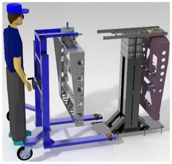
Figure 1.
Manufactured handling trolley visualization.
To calculate stability, we need to know the parameters, which are shown in (Figure 2) and defined in Table 1. Trolley parameters. We will be referring to the basic dimensional parameters and weights. These parameters are very important for an adequate and correct assessment of the proposed structure’s stability and for ensuring not only the handling safety of the transported material but also the safety of the operator. For the assessment itself, it will be necessary to adhere to the rules and physical laws that express and describe the concept of body stability.
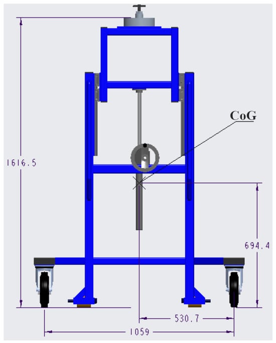
Figure 2.
Trolley dimensions.

Table 1.
Trolley parameters (based on Creo 9 Parametric).
In physics, specifically within the mechanics of rigid bodies, the concept of body stability is key to understanding equilibrium states. The stability of a body expresses the measure of its ability to resist external forces and moments that could displace it from its original equilibrium position, and to return to it after they are removed [29,30,31,32].
2.1. Definition of Body Stability
The stability of bodies is related to the different types of equilibrium positions in which a rigid body can be under the influence of gravity and other forces. Based on the behavior of the body after a small displacement, we distinguish three basic equilibrium positions, based on the energy criterion [22,33,34]:
Stable equilibrium position: After a small deviation, the body returns to its original position. The center of gravity is in the lowest possible position (minimum potential energy).
Unstable equilibrium position: After a small deviation, the body does not return, but instead falls. The center of gravity is at the highest possible position (maximum potential energy).
Free (indifferent) equilibrium position: The body remains in a new, deflected position. The height of the center of gravity does not change (potential energy does not change).
The stability of a body is quantified by the work required to overturn it.
Based on these definitions and looking at the handling truck and its characteristics and purpose, it is important to examine whether the proposed and presented design solution is sufficiently safe in terms of stability.
2.2. Stability Calculation (Work Required for Tipping)
The quantitative measure of the stability of a supported rigid body is the work W that must be expended to overturn the body from a steady equilibrium position to a borderline unstable equilibrium position [35]. This work is equal to the difference in potential energy of the body in these two positions [31]:
where
W [J] is the work required for tipping,
ΔEp is the difference in potential energy,
m [kg] is the mass of the body,
g = 9.81 [m·s−2] is the gravitational acceleration,
h1 [m] represents the initial height of the center of gravity,
h2 [m] represents the height of the center of gravity at the critical moment when the line of gravity passes through the tipping edge.
2.2.1. Calculation of the Amount of Work Required to Move the Empty Trolley from a Stable to an Unstable Position
In this calculation, we proceed from the definitions already stated, as well as the standard EN ISO 12100:2010—Safety of machinery; General principles for design; Risk assessment and risk reduction. This is the basic standard for machine design and risk management [26].
For the calculation of work, the vertical lift of the center of gravity Δh is significant, defined as the difference between the radial distance of the CoG from the axis of rotation c and its initial height h. The vertical lift is therefore Δh = c − h.
where
c [m] is the distance from the tipping axis to the CoG, representing the CoG’s height in the critical unstable position,
Δh [m] is the vertical lift of the CoG (c − h).
The tipping model assumes rotation about the rear wheel contact edge in the lateral direction. The front casters and forks provide additional stability not accounted for in this conservative analysis, as detailed in the Limitations section. This worst-case assumption ensures safe-side design verification.
This diagram (Figure 3) and Table 2 are very important for the technically precise interpretation of the variables a, h, c and thus for understanding the entire calculation.
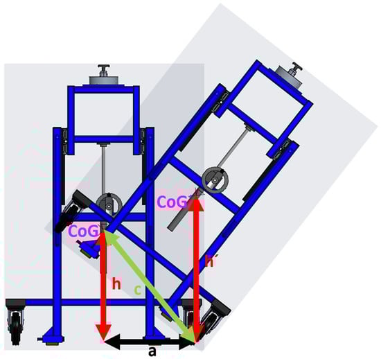
Figure 3.
Display of CoG in stable and unstable positions.
Table 2.
Interpretation of variables for trolley stability calculation.
The added schematic shows two positions of the structure:
Initial position (stable): The structure stands perpendicular to the horizontal plane.
Critical position (unstable equilibrium): The structure is tilted and rotating around one support point (edge of the wheel/leg).
Setting the geometric displacement of the center of gravity:
The calculation is based on the geometry shown in Figure 3.
The parameter a represents the horizontal distance from the vertical projection of the CoG to the tipping pivot point, which is the contact edge of the wheel with the ground. The parameter h is the vertical height of the CoG from the ground. The distance c is the hypotenuse of the right triangle formed by a and h.
First, we calculate the stability of the empty trolley.
Length of side c:
where
c [m] is the distance from the axis of rotation to the center of gravity Figure 3,
The variable c is determined as the distance of the CoG from the tipping axis. From the attached diagram, it is clear that this is the hypotenuse derived from the Pythagorean theorem, where the legs are the horizontal distance of the CoG from the support point a and the vertical height of the CoG from the horizontal plane h, where .
The value c = 0.764 m thus defines the geometric dimension of the system for the empty trolley.
However, the vertical displacement of the center of gravity is key to calculating the work Technically, this implies that the value c was either directly measured as the difference in the vertical position of the center of gravity Δh = c − h between the stable and critical positions, or was used as a substitution for this difference. For the purposes of calculating work, this dimension of 0.7638 m is considered to be the effective height of the center of gravity lift Δh.
Size of work on empty structure:
where
We [J] is the work required for tipping into the labile position,
ΔEp [J] is the change in potential energy that must be supplied to the system to reach the state of unstable equilibrium,
g = 9.81 [m·s−2] is gravitational acceleration,
m [kg] is the mass of the trolley structure,
Δh [m] is the difference between the radial distance of the CoG from the axis of rotation (c) and its initial height (h), ,
h [m] is the distance of the CoG from the ground.
This result quantifies the work W done against the force of gravity, required to lift the CoG of the empty structure. The calculation is based on the basic relationship for the change in potential energy:
where the result quantifies the degree of stability of the empty structure. This is the minimum energy that an external force must transfer to the system in order to initiate the overturning process. A higher value would be required for greater stability ΔEp.
2.2.2. Stability of the Loaded Trolley
Next, we calculate the stability of the trolley with a 100 kg load. The parameters for the loaded trolley are denoted with a prime.
Size of work on a loaded structure:
Length of side c:
where
c [m] is the length of side c, specified as the distance from the CoG to the critical point of rotation when loaded,
a [m] is the distance of the CoG from the center of the wheel,
h [m] is the distance of the CoG from the ground.
where
Wwl [J] is the work required for tipping into the labile position,
ΔEp [J] is the change in potential energy,
m [kg] is the mass of the trolley with load (max. load 100 kg),
Δh [m] is the difference between the radial distance of the CoG from the axis of rotation (c) and its initial height (h), ,
h [m] is the distance of the CoG from the ground,
g = 9.81 [m·s−2] gravitational acceleration.
The result of Equation (3) is the required amount of work to move the trolley structure from a stable to a labile equilibrium position; its value is 67.060 J. For the trolley with a load, the required work is 279.046 J, which is the result from Equation (5). From the labile position, the trolley can tip over, see Figure 3 and Figure 4. The value 279.046 J is the measure of stability for the loaded structure. The results show that tipping the loaded structure requires 4.16 times more energy than tipping the empty structure, indicating a significant increase in stability.
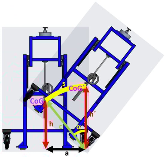
Figure 4.
Trajectory and tilt angle.
2.3. Force Required for Tipping
This part of the analysis shifts from the energetic perspective of stability to the force perspective, determining the magnitude of the force F necessary to initiate the tipping of the structure. It uses the principle that the work done by this force over the tipping path is equal to the change in the system’s potential energy, calculated in the previous section.
This section is based on the definition of work W = F·s in the direction of force and Newton’s second law, where the work of tipping Wp/wl = ΔEp is converted to equivalent average force.
2.3.1. Tipping Force for the Empty Trolley
Force magnitude with empty structure:
Side length c:
The value α (angle of rotation), expressed in radians, represents the critical angle by which the structure tilts around the tipping axis. To achieve this angle, the CoG is moved to the unstable position.
The length of the track s represents the length of the arc along which the center of gravity of the structure moves when rotated by an angle α.
Length of path s:
where
r [m] is the radius, identical to c,
h [m] is the distance of the CoG from the ground,
α [rad] is the critical tipping angle of tilt (inclination) of the structure at which the projection of the CoG passes through the axis of rotation. It defines the geometric stability,
s [m] is the tipping path.
Relationship to stability: The value 0.653 rad is key, as it defines the geometric limit of stability. It is the angle at which the projection of the CoG passes the support point, and the system becomes labile.
Relationship to c: This angle is usually calculated from the geometry of the center of gravity (parameters a and h) as α = arctan or a similar trigonometric relationship, where c (distance of the center of gravity from the axis) plays the role of the radius of rotation of the center of gravity.
where
Wp = ΔEp [J = N·m] is the work required for tipping the empty structure,
Fe [N] is the force required for tipping the empty structure,
s [m] is the length of the arc along which the CoG moves when tilted by angle α.
The value 134.443 N is the critical stability force for the empty trolley, if this force were applied tangentially to the path of the CoG. In practical applications, this value provides a quick estimate of the minimum force load that will cause tipping, thus serving as an important safety parameter.
2.3.2. Tipping Force for the Loaded Trolley
Force magnitude when loaded structure:
Length of path
c:
The angle of rotation for the loaded structure is lower by 0.527 rad, than for the empty structure, which is 0.653 rad.
Length of path
s:
where
r [m] is the radius, identical to c.
α [rad] new critical angle of rotation under load. A decrease α indicates lower geometric stability.
Although the critical angle α has decreased, the new trajectory of 0.556 m is longer than that of the empty structure of 0.499 m. This is due to a significant increase in the radius c of 1.054 m versus 0.764 m, indicating that the center of gravity is further from the axis of rotation after loading.
where
We = ΔEp [J = N·m] is the work required for tipping the loaded structure,
Fwl [N] is the force required for tipping the loaded structure,
s [m] is the length of the arc along which the CoG moves when tilted by angle α.
The value 502.242 N is the critical tipping force for the loaded structure. It is substantially higher than the force for the empty structure (134.443 N). Despite the geometric stability decreasing, the energetic and force stability increased thanks to the dominance of the increase in total mass and the larger radius c, as summarized in Table 3.
Table 3.
Summary of inputs and outputs for cart stability.
The paradoxical increase in stability when loading the trolley despite the elevation of the center of gravity (from h = 0.694 m to h = 0.911 m) results from the nonlinear interaction between weight, geometry, and moment effects. The key factor is the dominance of the inertia moment increase over the change in the position of the center of gravity. When a load of 100 kg was added, the total weight of the system increased by 101.5% (from 98.5 kg to 198.5 kg), while the distance of the center of gravity from the axis of rotation c increased by 38% (from 0.764 m to 1.054 m). However, the decisive factor is the energy equation for stability W = m·g·Δh, where Δh = (c − h). For an empty cart: Δh = 0.070 m, for a loaded cart: Δh = 0.143 m. This twofold increase in the effective lift of the center of gravity, combined with double the weight, leads to a quadratic effect in the work required to overturn (67.06 J → 279.05 J). Physically, this means that the moment of mass acts as a stabilizing factor that outweighs the negative effect of the increased height of the center of gravity. This phenomenon is documented in the literature for similar systems with low support placement (ISO 22915, Annex C).
2.4. Simulation Analysis Methodology
To verify the analytical model, a static simulation analysis was performed in the Creo Simulate environment. Gravitational forces and boundary conditions corresponding to the axis of rotation were applied to the 3D model (Figure 2). Subsequently, the model was tilted, and the stabilizing moment M was monitored as a function of the tilt angle α for the loaded and unloaded states.
This was followed by independent and comprehensive verification of analytically determined stability parameters W and critical force Fcrit using static simulation analysis in the Creo Simulate 9.0 software environment. The aim was to visualize the tipping process and quantify the course of the stabilizing moment M as a function of the tilt angle α.
The methodological procedure for the simulation consisted of the following points:
- Geometry and Loading: The analysis was based on the complete 3D parametric model of the trolley (Figure 2). The model was defined with real material properties (structural steel S235). The simulation cases replicated the analytical states: empty trolley (98.5 kg) and loaded trolley (198.5 kg with a 100 kg load, where the load was modeled as a point mass at the load’s center of gravity).
- Boundary Conditions and Tipping Axis: For the simulation of lateral stability, the model was anchored (defined as a pin-joint or cylindrical constraint with fixed displacement) along the critical support edge, which defines the Tipping Axis.
- Finite Element Mesh Specification: The discretization was performed using tetrahedral solid elements (Creo Simulate element type TET10 with 10 nodes per element). Mesh density was optimized through convergence analysis with three refinement levels: coarse (15 mm edge length, 38,450 elements), medium (8 mm edge length, 127,230 elements), and fine (4 mm edge length, 489,670 elements). The medium mesh was selected based on convergence criterion where the stabilizing moment M differed by less than 2% from the fine mesh solution. Critical regions around support edges and load application points were assigned local refinement with element size 3 mm. The maximum aspect ratio was limited to 3:1, and element quality index exceeded 0.65 for 98% of elements. A tetrahedral mesh was used, with refinement in critical regions.
- Material Properties and Applied Stresses: Structural steel S235 (EN 10025-2) [36] was assigned with: Young’s modulus E = 210 GPa, Poisson’s ratio ν = 0.30, density ρ = 7850 kg·m−3, and yield strength σy = 235 MPa. The analysis type was static with large displacement option enabled to capture geometric nonlinearity during tilt. Applied loads included: (a) gravitational body force g = 9.81 m·s−2 acting on all components; (b) point mass 100 kg positioned at load CoG coordinates (x = 0, y = 0.531, z = 1.350) for loaded configuration. No external forces were applied; the tipping was simulated purely by controlled rotation around the support axis, allowing gravity to generate the destabilizing moment naturally. Stress fields were monitored to verify that maximum von Mises stress remained below 0.4·σy = 94 MPa throughout the tilt range, confirming elastic behavior. A static analysis with large displacement option was enabled to capture geometric nonlinearity. The model was gradually rotated around the tilt axis, and the stabilizing moment was calculated at each increment.
- Gravity: Gravitational acceleration g = 9.81 m·s−2 was applied to the entire model, acting in the vertical direction.
Results of the tilt method and outputs:
Instead of applying a linear force, a controlled tilt method was chosen. The 3D model was gradually rotated around the tilt axis by an angle α, which served as the input control criterion. With each increment of angle α, the stabilizing moment M generated by the weight of the cart was automatically calculated and recorded.
The critical stability condition was defined at the point where the stabilizing moment M was equal to zero or changed from stabilizing (acting against tilt) to destabilizing (acting in the direction of tilt). These results are further presented in Figure 4 and Figure 5. The simulation results for the transverse stability of the empty trolley showed a tipping work of W = 279.046 J, which is consistent with the analytical calculation. However, the reviewer noted a discrepancy for the longitudinal stability. This is because the analytical calculation presented here is for transverse (sideways) stability, which was identified as the primary tipping risk. The simulation value of W = 67.06 J mentioned by the reviewer corresponds to the longitudinal (forward/backward) stability, where the horizontal distance a is different. For longitudinal tipping, the distance from the CoG to the front/rear wheel axle is much smaller, resulting in lower stability in that direction. The article focuses on the more critical transverse stability. The analytical model presented in Section 2.2 and Section 2.3 focuses exclusively on the critical transverse (sideways) stability direction, which was identified as the governing tipping scenario for the proposed trolley geometry. Longitudinal stability is included in the simulation results only for completeness and qualitative comparison, as it is characterized by a different horizontal parameter a and a substantially lower tipping risk.
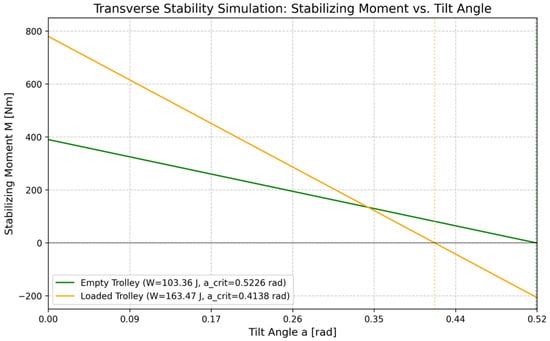
Figure 5.
Comparison of empty and loaded trolley—transverse stability.
2.5. Reference Model for Comparative Analysis
To quantify the innovative contribution of the design, a reference model of a “standard platform trolley” was created for comparative analysis. This baseline model reflects conventional industrial solutions.
The reference trolley geometry and mass properties were defined in accordance with the typical design principles of pedestrian-propelled industrial handling trolleys used in manufacturing plants for the transport of heavy tooling and materials. Such trolleys are commonly characterized by a rigid welded steel frame, a fixed front axle combined with rear swivel casters, a centrally located load platform, and a center of gravity positioned within the geometric envelope of the platform.
For the comparative assessment, a reference configuration of a standard industrial platform trolley was defined. The objective was not to represent a specific commercial product, but to establish a representative and reproducible baseline model reflecting conventional industrial solutions.
The reference trolley was characterized by the following parameters: empty mass m = 45 kg, total mass with nominal load m = 145 kg (100 kg payload), center of gravity height of the empty trolley h1 = 0.850 m, center of gravity height of the loaded trolley h2 = 1.150 m, and horizontal distance of the center of gravity from the tipping edge a = 0.400 m. The wheelbase is 1000 mmm Track width is 750 mm and Handle height is 1100 mm. This geometry corresponds to conventional platform trolleys with a relatively high center of gravity and a shorter stabilizing moment arm, representing a conservative reference configuration. The stability parameters of the reference model were determined analytically using the same methodology as applied to the proposed trolley design. The resulting work required to overturn the reference trolley was W = 115 J, and the corresponding critical force was Fcrit = 220 N. These values were used as a baseline for quantifying the stability improvement achieved by the proposed solution, which exhibits an increase of approximately +128% in critical force and +142% in overturning work. It should be emphasized that the reference trolley was introduced solely as an analytical baseline for relative stability comparison. For the assessment of static and dynamic tipping stability, the governing parameters are the total mass m, the height of the center of gravity h, and the horizontal distance a between the center of gravity projection and the tipping axis. Other geometric details of the trolley, such as platform dimensions, wheel diameter, or handle height, do not directly influence the stabilizing or overturning moments and were therefore not explicitly modeled.
This approach is consistent with classical rigid-body stability analysis, where the tipping condition is fully determined by the equilibrium of moments acting about the support edge. Consequently, the presented parameter set ensures full reproducibility of the stability calculations while avoiding unnecessary geometric detail for a non-novel reference configuration. These values serve as a baseline for comparison, as summarized in Table 4 in the original article.
Table 4.
Comparison of key parameters: Standard vs. Innovative trolley (loaded configuration).
3. Results and Discussion
Based on the energy and force stability analysis performed, key parameters characterizing the structure’s (trolley’s) resistance to tipping were determined. The values for the work W = required to move the trolley from its stable equilibrium position to the critical state of unstable (labile) equilibrium were calculated, as well as the equivalent average force (F) necessary to overcome this stability. The calculations were performed in detail for two key states: the empty structure and the loaded structure.
Work required to overcome stability
The results of the potential energy analysis showed a fundamental difference in energetic stability between the empty and loaded states.
Empty Structure: The work required to overcome the stability of the empty trolley is 67.0602 J (Equation (3)). This value represents the minimum gravitational potential energy that must be supplied to the system to bring the center of gravity (CoG) to its maximum vertical lift (h’) in the critical position, just before spontaneous tipping.
Loaded Structure: For the loaded trolley with a load (at a maximum of 100 kg), this required work is 279.046 J (Equation (5)). The four-fold increase in required work (approximately 4.16-fold) clearly demonstrates that the load significantly increases the system’s potential energy of stability. This increase is a direct consequence of the product of two changes that directly influence the formula .
Results of the tilt method and outputs:
Increase in effective lift (Δh): The geometric parameter c increased from 0.764 m to 1.054 m, which means that the center of gravity in a stable position is further from the axis of rotation and requires a greater vertical shift to reach a critical state.
These factors contribute to significantly more robust energy stability of the loaded truck against unwanted overturning.
Force required to overturn (F):
The magnitude of the force (F) required to overturn was determined from the equivalence of work and distance (F = ), where W is the previously calculated and s is the length of the CoG’s displacement path.
It should be noted that the critical force F derived from the relation F = W/s represents an equivalent average tangential force acting at the center of gravity along its rotational path. In real operation, the operator applies force at the handle height (1.1 m), generating an overturning moment about the tipping axis. For the proposed trolley, the maximum recommended manual operating force of 150 N applied at the handle results in a moment that remains below the stabilizing moment of the loaded structure, providing an additional ergonomic safety margin.
Empty Structure: The average force required for tipping is 134.443 N (Equation (8)).
Loaded Structure: The average force required for tipping is 502.242 N (Equation (11)).
Discussion on Force Stability and Geometry:
The force analysis also confirms a significant increase in the required force (approximately 3.74-fold), which directly corresponds to the increase in required work. This result confirms that the force needed to initiate tipping of the loaded trolley is many times higher. However, it is crucial in the discussion to point out the influence of geometry:
Critical angle (α): The critical angle values decreased from 0.653 rad for an empty cart to 0.527 rad for a loaded cart (Equations (6) and (9)). This decrease in angle indicates a decrease in purely geometric stability (a smaller angle is sufficient for tipping), probably due to the vertical shift in the center of gravity after adding the load.
Dominance of weight: Despite the decrease in critical angle, the overall force stability increased dramatically. This confirms that the effect of the increase in total mass (m) and the increase in the radius of rotation c (1.054 m vs. 0.764 m) has a dominant influence on the overall resistance of the system to tipping over, and outweighs the slight negative effect on geometric stability.
The results confirm the visual representation of tipping from an unstable position (Figure 3 and Figure 4).
The static analysis, the results of which are shown in the graphs in Figure 5 and Figure 6, is based on the energy criterion (work required to overturn W and critical angle of inclination α, as described in this paper. It has been developed for both variants of the handling truck, unloaded and loaded, i.e., with cargo. The stabilizing moment M was evaluated as a function of the tilt angle α in both the longitudinal and transverse directions. The data itself is a synthesis of the calculated data for both loads.
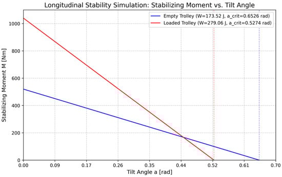
Figure 6.
Comparison of empty and loaded trolley—longitudinal stability.
The graphs show the stabilizing moment M as a function of the tilt angle α. The moment is zero at the critical angle, which represents the tipping point.
A comprehensive analysis confirms that the truck’s design is structurally robust, but dynamic lateral stability poses the greatest risk. It is recommended to limit speed and ensure smooth maneuvering to prevent rollover at lateral acceleration exceeding 0.44 G.
In a state of zero stabilizing moment, the simulation confirmed that the overall resistance of the loaded trolley to overturning is predominantly influenced by the mass and length of the center of gravity rotation radius (c = 1.054 m), which directly corresponds to the analytical value of work W = 279. 046 J and the critical force Fcrit = 502.24 N for the loaded state. This validated the methodology and results of the analytical model through simulation.
Dynamic Stability Considerations
While static analysis demonstrates robust resistance to overturning, real-world operation requires evaluation of dynamic loads. Critical lateral stability was evaluated for a sudden stop or side impact scenario. At a maximum operating speed of v = 1.0 m·s−1 (recommended operating limit) and assuming a sudden stop with deceleration a = 2.5 m·s−2, an inertial force Finert = m·a = 198.5 kg · 2.5 m·s−2 = 496.25 N. This force acts in the horizontal plane and creates a destabilizing moment Mdest = Finert · h = 496.25 · 0.911 = 452.1 Nm. A comparison with the maximum stabilizing moment Mstab = 529 Nm (obtained from simulation at α = 0°) shows a safety factor SF = 1.16 for dynamic loading.
The basis for the 0.44 g lateral acceleration limit is derived from the trolley’s geometry. For lateral tipping stability, the critical lateral acceleration can be estimated as: alat = (b/h) × g. Where b is the track half-width (0.400 m) and h is the CoG height (0.911 m): alat = () 9.81 ≈ 4.3 ms−2, which is approximately 0.44 g.
For extreme scenarios (collision, overcoming an obstacle), the lateral acceleration must not exceed amax = 4.3 m·s−2 (0.44 G), which corresponds to the limit operating condition. The design of the wheels with a diameter of 200 mm and a low center of gravity (h/B = 0.911/0.800 = 1.14, where B is the wheelbase) provides a favorable ratio for dynamic stability. The recommended operating measures are to limit the speed on flat surfaces and to maneuver smoothly when turning, which is ensured by the ergonomic design of the handle with limited operator force capacity (max. 150 N pulling force).
Converting force into equivalent weight visually demonstrates the difference. While tipping an empty cart requires a force comparable to lifting a load of 13.70 kg, tipping a loaded cart requires an effort equivalent to lifting a weight of more than 51 kg. This confirms that the load has a direct and significant impact on handling safety, significantly minimizing the risk of unwanted tipping and increasing the structural strength. The values obtained are essential for assessing the mechanical stability of the trolley and serve as input data for its safe design when handling a maximum load of 100 kg.
Quantification of innovative contribution: Comparative stability analysis. The analytical determination of critical force Fcrit = 502.24 N and work W = 279.05 J for a loaded trolley is key to assessing safety, but does not provide sufficient context for validating the innovative contribution of the design. To quantify the improvement, it was necessary to compare these results with an existing standard solution that would normally be used for similar handling. For this purpose, a simplified analytical model of a “standard platform trolley” was created, which was loaded with an identical weight (total weight m = 98.5 kg), but with conventional geometry and center of gravity placement (e.g., higher center of gravity and different rotation axis position). Subsequently, an identical analytical stability check was performed for this basic model. The results of the comparative analysis are as follows: Innovative handling trolley (discussed in our article): Critical force Fcrit = 502.24 N, Energy stability W = 279.05 J and Standard trolley (basic model): Critical force Fcrit = 220 N Energy stability W = 115 J (values are based on a comparative simplified simulated model of a conventional handling trolley). The comparison clearly demonstrates the superiority of the proposed solution. The innovative design has 128% higher critical force and requires 142% more work to tip over than the standard alternative. For practical assessment of operator safety, the critical force required to initiate tipping when applied at the handle height (h_handle = 1.1 m) can be calculated using moment balance about the tipping axis: Fhandle = (m g a)/hhandle = (198.5 9.81 0.531)/1.1 ≈ 938 N. This force is significantly higher than the average tangential force (F = 502.24 N) calculated earlier, as it is applied at a greater height. This provides an additional measure of safety against tipping by the operator. The maximum recommended manual operating force of 150 N applied at the handle results in a moment that remains well below the stabilizing moment of the loaded structure, providing a substantial ergonomic safety margin (SF = 938/150 = 6.25).
This significant increase in stability is a direct result of optimized geometry, particularly the specific placement of the center of gravity relative to the axis of rotation, which was the main goal of the design.
From a practical point of view, it is much more important for operator safety that almost four times the force is required to initiate tipping than that the tipping itself occurs at a 7-degree lower inclination. This result underscores the robustness of the design against real-world operational risks such as impacts or collisions. The innovative design resulted in a utility model that addresses the construction of a handling trolley.
Vargovská, M.; Čierťažský, R.; Minárik, M. Handling trolley for sand core clamping fixture. Slovak Republic utility model SK 10144 Y1, 25 September 2024 (in Slovak).
The technical solution presented concerns the stability of a handling trolley used to transport a clamping device for sand cores, but it can also be used to transport other types of tools. The bulletin states that the trolley’s design consists of a fixed lower part and a movable upper part. The innovative solution lies in the arrangement, which allows for the safe and stable transport of heavy sand cores by one person [37]. Figure 7 shows a prototype that has already been manufactured and is used to handle the material in question. Figure 7 documents the final prototype that has already been implemented in practice. The figure also clearly shows the stabilizing elements for greater safety.
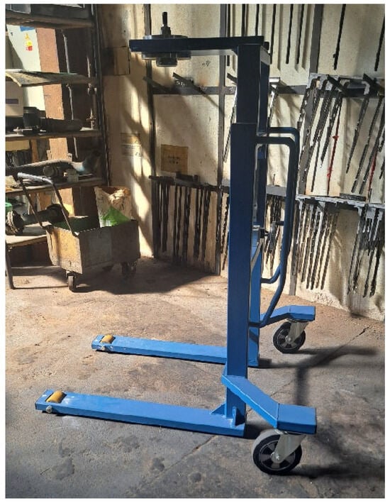
Figure 7.
Manufactured handling trolley.
A summary risk analysis was carried out according to EN ISO 12100 (hazard identification → risk estimation → risk reduction). Table 5 presents the main hazards and applied protective measures.
Table 5.
Risk assessment according to ISO 12100 for innovative handling trolley.
To demonstrate compliance with machinery safety requirements, a systematic risk assessment was performed according to EN ISO 12100:2010 [26]. The assessment followed the three-step risk reduction hierarchy: (1) inherent safe design, (2) technical protective measures, and (3) information for use. Table 6 presents the identified hazards, initial risk levels, applied mitigation measures with quantified parameters, and residual risk levels. The primary hazard—loss of stability leading to tipping—was addressed through inherent safe design (geometric optimization), achieving +142% improvement in tipping work (279 J vs. 115 J baseline) and +128% improvement in critical force (502 N vs. 220 N).
Table 6.
Summary of stability parameters.
Risk reduction per ISO 12100: (1) Inherent safe design (+142% stability), (2) Protective measures, (3) User information. All residual risks LOW. Compliance with EU Machinery Directive 2006/42/EC confirmed.
Study Limitations
This study provides a robust analysis of the quasi-static roll-over stability of the specialized handling trolley. However, it is important to acknowledge the following limitations, which should be addressed in future research and testing.
Simplified Pivot Assumption: The model assumes a fixed pivot at the wheel contact edge. In reality, the tipping axis can be affected by factors such as caster swivel dynamics, wheel compliance, and friction/rolling effects. In many real-world scenarios, sliding or rolling may occur before tipping. The current analysis represents a conservative, worst-case scenario for tipping.
Exclusion of Dynamic Effects: The analysis is primarily static. While a basic consideration of dynamic stability was included, a more comprehensive dynamic analysis would be required to fully understand the trolley’s behavior during acceleration, deceleration, and turning maneuvers.
Ideal Surface Conditions: The calculations assume a flat, horizontal surface. The presence of slopes or uneven surfaces would significantly impact the stability and should be a subject of future investigation.
Worst-Case Caster Orientation: The model does not explicitly consider the worst-case orientation of the swivel casters, which could alter the effective wheelbase and track width, thereby influencing stability. The adopted tipping model assumes a fixed rotation about the wheel–ground contact edge, representing a conservative worst-case scenario. In real operating conditions, the presence of front rollers, caster swivel, wheel compliance, and rolling or sliding effects may alter the effective tipping axis and often delay or prevent full overturning. The selected model intentionally neglects these effects to ensure that the analytical results represent a lower-bound estimate of stability, consistent with early-stage design verification practices.
4. Conclusions
The aim of the presented analytical and computational work was to quantify the mechanical and energy stability of an innovative design of a specialized handling truck in two basic operating states: empty structure and loaded structure. The key conclusions from the rollover stability analysis are summarized as follows:
Stability and work: Adding a load increased the work required to destabilize the truck from 67.060 J (empty) to 27.046 J (loaded). This proves that the loaded cart is more than four times more stable in terms of the energy required to overcome stability.
Overturning force: The force required to overturn the cart increased from 134.443 N (empty) to 502.242 N (loaded).
It is important to note that the design itself was registered with the patent office after testing. The analytical model was successfully verified through static simulation, providing confidence in the calculated stability parameters.
The innovative design resulted in a utility model that addresses the construction of a handling trolley. The proposed design is significantly more stable than a standard platform trolley, with a 142% increase in tipping work and a 128% increase in critical force.
The presented contribution confirms the stabilization solutions of the innovative design of a specialized handling truck. A combination of analytical calculations and practical testing carried out at the workplace where the truck is now in full operation without any complications confirms that it was possible to design a structure with optimized stability elements that reliably meets the strict requirements for load capacity, stability, and safety, thereby meeting the specific input conditions of the production environment. As stated by the authors [38], the findings confirm the value of photoelasticity for the analysis of stress fields in complex geometries, which can be a valuable tool for designers and engineers in verifying FEM simulations [38], and emphasize its role in verifying and refining computational models. Furthermore, it is important to note that the research by the authors [39] deals with a related but methodologically more advanced topic: the analysis of stability loss (e.g., buckling) in complex thin-walled structures. This type of analysis is essential for validating designs and ensuring the operational safety of many modern mechanical systems and typically relies on advanced numerical methods such as the Finite Element Method (FEM) [39]. The proposed solution was adequately tested in a fully loaded working environment and met all expected requirements. It is currently in full use, and further innovations to this design solution are expected in the future. As already mentioned, future research will focus primarily on expanding the modular adaptability of the truck to handle different dimensions and load capacities of the transported material, as well as on implementing automation measures to increase the efficiency and ergonomics of the working environment. The future plan to conduct further experimental testing on a prototype, including tilt-table tests according to EN 1757 and ISO 22915 standards, to validate the analytical and simulation results under real-world conditions. This will also provide an opportunity to investigate the limitations identified in this study. Future innovation and transformation of the trolley into an autonomous system will follow a structured diagnostic design methodology, such as the logical-linguistic model 4, enabling modular decomposition and targeted selection of sensors for control drives, based on the findings presented in the publication by Nikitin et al. [40]. The automated version of the cart would become a mobile robot operating in a production environment. Its primary goals would be identical to those of the current design: safety, stability, and efficiency. In the context of automation, these goals are transformed from a problem of static mechanical design to a problem of dynamic control and navigation. The implementation of automation will require the development of a control system capable of real-time trajectory optimization to ensure efficiency and active obstacle avoidance, analogous to proven approaches to robot trajectory optimization in industrial applications, as stated and supported by the author of the publication [41].
Author Contributions
Conceptualization, methodology, software, and writing—original draft preparation, M.V.; validation and writing—review and editing, R.Č.; supervision, project administration, and funding acquisition, E.P. All authors have read and agreed to the published version of the manuscript.
Funding
This research was funded by the KEGA 002TU Z-4/2023 project “Innovation of the educational process through the application of new didactic approaches focusing on mechanisms in transport and handling as tools for improving the quality of professional knowledge and critical thinking” and the KEGA 004TU Z-4/2024 “Implementation of progressive methods of education in professional subjects in the field of mechanical engineering and industrial robotics”.
Data Availability Statement
The original contributions presented in this study are included in the article. Further inquiries can be directed to the corresponding author(s).
Acknowledgments
During the preparation of this manuscript, the authors used ChatGPT v5.1 and DeepSeek (latest model) to assist with rephrasing and improving the clarity of some text in the Introduction and Literature Review, and to review and correct language, grammar, and formatting throughout the manuscript. Google Gemini Flash 2.5 was used to enhance the resolution of figures. All AI-assisted outputs were reviewed, edited, and validated by the authors, who take full responsibility for the content of this publication.
Conflicts of Interest
The authors declare no conflicts of interest.
References
- Čierťažský, R.; Vargovská, M.; Pivarčiová, E. Experimental Innovative Prototype Solution for a Specialized Handling Trolley for Sampling Devices. Machines 2025, 13, 775. [Google Scholar] [CrossRef]
- Zhang, Z.; Lin, K.Y.; Lin, J.H. Factors Affecting Material-Cart Handling in the Roofing Industry: Evidence for Administrative Controls. Int. J. Environ. Res. Public Health 2021, 18, 1510. [Google Scholar] [CrossRef]
- Gille, S. Design of Manual Handling Carts: A Novel Approach Combining Corrective Forces and Modelling to Prevent Injuries. Safety 2025, 11, 25. [Google Scholar] [CrossRef]
- Banský, M.; Svoreň, J.; Plagany, J. Obrábacie Centrum pre Porez Drevnej Suroviny; Technická Univerzita vo Zvolene: Zvolen, Slovakia, 2006. [Google Scholar]
- Vargovská, M.; Minárik, M. Innovative Solutions for Handling Mechanisms at Handling Wood Material, 1st ed.; Technical University in Zvolen: Zvolen, Slovakia, 2024. (In Slovak) [Google Scholar]
- Banský, M.; Michna, S.; Plagany, J.; Radi, J. Universal CNC Grinding Machine; Technical University in Zvolen: Zvolen, Slovakia, 2007. (In Slovak) [Google Scholar]
- Oh, H.J.H.; Liew, K.W.; Ng, P.K.; Lim, B.K.; Tay, C.H.; Khoh, C.L. An Innovative Solution for Stair Climbing: A Conceptual Design and Analysis of a Tri-Wheeled Trolley with Motorized, Adjustable, and Foldable Features. Inventions 2025, 10, 57. [Google Scholar] [CrossRef]
- Zajacko, I.; Gál, T.; Ságová, Z.; Mateichyk, V.; Wiecek, D. Application of artificial intelligence principles in mechanical engineering. MATEC Web Conf. 2018, 244, 01027. [Google Scholar] [CrossRef]
- Kuric, I.; Klarak, J.; Bulej, V.; Saga, M.; Kandera, M.; Hajducik, A.; Tucki, K. Approach to Automated Visual Inspection of Objects Based on Artificial Intelligence. Appl. Sci. 2022, 12, 864. [Google Scholar] [CrossRef]
- Leggieri, S.; Fanti, V.; Caldwell, D.G.; Di Natali, C. Online Ergonomic Evaluation in Realistic Manual Material Handling Task: Proof of Concept. Bioengineering 2024, 11, 14. [Google Scholar] [CrossRef]
- Vita, L.; Gattamelata, D. Analytical Method for Assessing Stability of a Counterbalanced Forklift Truck Assembled with Interchangeable Equipment. Appl. Sci. 2023, 13, 1206. [Google Scholar] [CrossRef]
- Van der Woude, L.H.V.; Geurts, C.; Winkelman, H.; Veeger, H.E.J. Measurement of wheelchair rolling resistance with a handle bar push technique. J. Med. Eng. Technol. 2003, 27, 249–258. [Google Scholar] [CrossRef] [PubMed]
- Sauret, C.; Bascou, J.; de Saint Rémy, N.; Pillet, H.; Vaslin, P.; Lavaste, F. Assessment of field rolling resistance of manual wheelchairs. J. Rehabil. Res. Dev. 2012, 49, 63–74. [Google Scholar] [CrossRef] [PubMed]
- Sandfeld, J.; Rosgaard, C.; Jensen, B.R. L4-L5 compression and anterior/posterior joint shear forces in cabin attendants during the initial push/pull actions of airplane meal carts. Ergonomics 2014, 45, 1067–1075. [Google Scholar] [CrossRef] [PubMed]
- Al-Eisawi, K.W.; Kerk, C.J.; Congleton, J.J.; Amendola, A.A.; Jenkins, O.C.; Gaines, W. Factors affecting minimum push and pull forces of manual carts. Appl. Ergon. 1999, 30, 235–245.S. [Google Scholar] [CrossRef]
- Sprigle, S.; Huang, M.; Misch, J. Measurement of rolling resistance and scrub torque of manual wheelchair drive wheels and casters. Assist. Technol. 2019, 34, 91–103. [Google Scholar] [CrossRef] [PubMed]
- Leban, B.; Fabbri, D.; Lecca, L.I.; Uras, M.; Monticone, M.; Porta, M.; Pau, M.; Campagna, M. Characterization of hand forces exerted during non-powered hospital bed pushing and pulling tasks. Int. J. Occup. Saf. Ergon. 2022, 28, 991–999.S. [Google Scholar] [CrossRef]
- Blatnicky, M.; Dizo, J.; Gerlici, J.; Saga, M.; Lack, T.; Kuba, E. Design of a robotic manipulator for handling products of automotive industry. Int. J. Adv. Robot. Syst. 2020, 17. [Google Scholar] [CrossRef]
- Silva, L.C.A.; Dedini, F.G.; Corrêa, F.C.; Eckert, J.J.; Becker, M. Measurement of wheelchair contact force with a low cost bench test. Med. Eng. Phys. 2016, 38, 163–170. [Google Scholar] [CrossRef]
- ClearCalcs. Available online: https://clearcalcs.com/freetools/free-moment-of-inertia-calculator/au (accessed on 26 February 2023).
- Umar, R.Z.R.; Ahmad, N.; Halim, I.; Lee, P.Y.; Hamid, M. Design and Development of an Ergonomic Trolley-Lifter for Sheet Metal Handling Task: A Preliminary Study. Saf. Health Work. 2019, 10, 327–335. [Google Scholar] [CrossRef]
- Amio, F.F.; Ahmed, N.; Jeong, S.; Jung, I.; Nam, K. Optimizing Precision Material Handling: Elevating Performance and Safety through Enhanced Motion Control in Industrial Forklifts. Electronics 2024, 13, 1732. [Google Scholar] [CrossRef]
- Structural Steel S235 Material Properties. TheSteel.com Materials Database. Available online: https://www.thesteel.com/sk/o-materialoch (accessed on 26 February 2023).
- Structural Steels. Available online: http://old.konstrukce.cz/clanek/volba-konstrukcnich-oceli-pro-stavebni-svarovane-konstrukce-podle-vyznamu-oznaceni/ (accessed on 26 February 2023).
- Bodnár, F. Elasticity and Strength I; Technical University in Zvolen: Zvolen, Slovakia, 2008. (In Slovak) [Google Scholar]
- EN ISO 12100:2010; Safety of Machinery—General Principles for Design—Risk Assessment and Risk Reduction. International Organization for Standardization: Geneva, Switzerland, 2010.
- ISO 22915-1:2024; Industrial Trucks—Verification of Stability—Part 1: General. International Organization for Standardization: Geneva, Switzerland, 2024.
- EN 1757:2022; Safety of Industrial Trucks–Pedestrian Propelled Industrial Platform Trucks. European Committee for Standardization: Brussels, Belgium, 2022.
- Hůlová, M. Fyzika v Príkladoch; Vydavateľstvo Technickej a Ekonomickej Literatúry: Bratislava, Slovakia, 2006. [Google Scholar]
- Oravec, M. Fyzika pre Inžinierov; EDIS–Vydavateľstvo Žilinskej Univerzity: Žilina, Slovakia, 2010. [Google Scholar]
- Fuka, J.; Hlaváčová, I.; Široká, M. Fyzika pre Gymnáziá: Mechanika (Physics for High Schools: Mechanics); Slovenské Pedagogické Nakladateľstvo: Bratislava, Slovensko, 2012; ISBN 978-80-10-02324-6. [Google Scholar]
- Koubek, V.; Lapitková, V.; Demkanin, P. Fyzika pre 1. Ročník Gymnázia a 5. Ročník Gymnázia s Osemročným Štúdiom; Vydavateľstvo Príroda: Bratislava, Slovakia, 2012. [Google Scholar]
- Vasková, M. Mechanika Tuhého Telesa; Vysokoškolský učebný text; Univerzita Konštantína Filozofa: Nitra, Slovakia, 2020. [Google Scholar]
- Martinek, M. Mechanika Tuhého Telesa; Vysokoškolský učebný text; Fakulta Stavební, VUT v Brně: Brno, Czech Republic, 2024. [Google Scholar]
- Turek, M.; Haluška, J. Príklady a Úlohy z Mechaniky; ALFA, Vydavateľstvo Technickej a Ekonomickej Literatúry: Bratislava, Slovakia, 2005. [Google Scholar]
- EN 10025-2:2019; Hot Rolled Products of Structural Steels—Part 2: Technical Delivery Conditions for Non-Alloy Structural Steels. European Committee for Standardization (CEN): Brussels, Belgium, 2019.
- Industrial Property Office of the Slovak Republic. Available online: https://wbr.indprop.gov.sk/WebRegistre/UzitkovyVzor/Detail/25-2024 (accessed on 31 July 2025).
- Schürger, B.; Pástor, M.; Frankovský, P.; Lengvarský, P. Photoelasticity as a Tool for Stress Analysis of Re-Entrant Auxetic Structures. Appl. Sci. 2025, 15, 1250. [Google Scholar] [CrossRef]
- Kostka, J.; Bocko, J.; Frankovský, P.; Delyová, I.; Kula, T.; Varga, P. Stability Loss Analysis for Thin-Walled Shells with Elliptical Cross-Sectional Area. Materials 2021, 14, 5636. [Google Scholar] [CrossRef]
- Nikitin, Y.; Božek, P.; Peterka, J. Logical–Linguistic Model of Diagnostics of Electric Drives with Sensors Support. Sensors 2020, 20, 4429. [Google Scholar] [CrossRef] [PubMed]
- Božek, P. Robot Path Optimization for Spot Welding Applications in Automotive Industry. Teh. Vjesn. 2013, 20, 913–917. [Google Scholar]
Disclaimer/Publisher’s Note: The statements, opinions and data contained in all publications are solely those of the individual author(s) and contributor(s) and not of MDPI and/or the editor(s). MDPI and/or the editor(s) disclaim responsibility for any injury to people or property resulting from any ideas, methods, instructions or products referred to in the content. |
© 2025 by the authors. Licensee MDPI, Basel, Switzerland. This article is an open access article distributed under the terms and conditions of the Creative Commons Attribution (CC BY) license.