Abstract
This paper proposes a new Asymmetric Permanent Magnet Vernier Motor (A-PMVM) for low-speed high-torque applications. Unlike conventional symmetric V-shaped PMVMs (SV-PMVMs), the A-PMVM features irregular U-shaped magnet arrays composed of asymmetric V-shaped magnets. Finite element analysis confirms its superior performance: 10.6% higher torque (19.67 N·m vs. 17.78 N·m), 22% reduced PM volume (37,500 mm3 vs. 48,000 mm3), and 53% lower cogging torque (0.32 N·m vs. 0.68 N·m peak-peak). While exhibiting higher initial torque ripple ratio (8.65%), multi-objective optimization suppresses torque ripple ratio by 5.32% (from 8.65% to 8.19%), reduces cogging torque 12.5% (from 0.32 N·m to 0.28 N·m), and enhances torque by 0.76% (from 19.67 N·m to 19.82 N·m). The optimized A-PMVM achieves a significant reduction in cogging torque and torque ripple ratio, demonstrating significant potential for applications like wind turbines and electric vehicles. Additionally, this paper confirms that the proposed motor maintains consistent performance during both clockwise and counterclockwise operation.
1. Introduction
Permanent magnet motors (PMMs) have been extensively employed in industrial and residential applications due to their high torque density and efficiency [1,2]. With advancing industrial technologies, performance requirements for electric motors—particularly regarding compactness, weight reduction, and energy efficiency—have become increasingly stringent [3,4]. PMMs must deliver exceptional starting load capacity in low-speed high-torque applications such as wind turbines and cranes, while high-precision domains like robotics and CNC machining demand higher torque-to-inertia ratios and miniaturization [5]. Conventional PMMs generate mechanical energy through the interaction of fundamental permanent magnet field and armature field sharing identical pole-pair number (PPN) in the air gap. However, their reliance on a single working harmonic, i.e., fundamental harmonic, renders them inadequate for modern low-speed high-torque applications [6,7,8,9].
To address these limitations, permanent magnet Vernier motors (PMVMs) have emerged as a promising solution. While structurally similar to conventional PMMs, PMVMs feature unequal pole-pair numbers (PPNs) between the permanent magnets (PMs) and armature windings. Typically, the number of pole pairs in PMs significantly exceeds that in armature windings. Through the field modulation by the irregular air gap, the multi-pole low-speed magnetomotive force (MMF) generates few pole high-speed magnetic flux density harmonics. This modulated magnetic flux density harmonics interacts with those magnetic flux density harmonics generated by armature field to produce torque [10]. Consequently, PMVMs emulate the torque-amplifying behavior of a “geared high-speed PM motor” while offering superior torque density and eliminating mechanical gearboxes [11,12]. These advantages make PMVMs particularly suitable for volume-constrained applications including wind power generation, electric vehicles, and marine propulsion [13,14,15,16]. Nevertheless, emerging applications with strict size/weight limitations, harsh environments, and limited cooling require further improvements in torque density [17,18].
References [19,20] comprehensively elucidate the operating principles of PMVMs, identifying three key design elements: field excitation sources, field modulation units, and harmonic filters. Specifically, the field excitation sources typically comprise PMs and armature currents; field modulation units are implemented via slotted iron cores in the stator/rotor, and harmonic filters refer to armature windings wound with specific pole-pair numbers, whose function is to selectively interact with modulated magnetic field harmonics and armature field harmonics for torque generation. From the perspective of these three elements, enhancing PMVM torque density primarily involves three approaches:
- Intensifying magnetic fields of the field excitation sources through flux-concentrating topologies (tangential-excitation, V-shaped, U-shaped and Halbach PM arrays, etc.) [21,22,23,24].
- Increasing permeance harmonic amplitudes induced by field modulation units. For example, PMVM with alternate-pole design further enhance the modulation effectiveness of the field modulation unit, reducing PM consumption by 50% while amplifying fundamental permeance component [25].
- Introducing multiple working harmonics via asymmetric designs. For instance, asymmetric stator/rotor tooth pitches produce additional permeance harmonics [26], achieving >20% torque density improvement across pole-slot combinations. Based on this method, reference [27] proposed a coded-tooth PMVM and optimized harmonic utilization.
Guided by asymmetric structural design, this paper proposes a new asymmetric permanent magnet Vernier motor (A-PMVM) to further enhance the torque capability. Distinct from conventional symmetric V-shaped permanent magnet Vernier motors (SV-PMVMs), the proposed motor features asymmetric V-shaped magnets, where two asymmetric V-shaped magnets constitute an irregular U-shaped magnetic array. The work presents the motor’s structure and working principle, validates its electromagnetic performance through finite element analysis (FEA), and demonstrates its advantages over a conventional SV-PMVM in torque density and PM consumption. Finally, multi-objective optimization is applied to enhance torque performance [28].
2. Structure and Working Principle
Figure 1 illustrates the structure of the proposed asymmetric permanent magnet Vernier motor (A-PMVM), comprising a stator and a rotor. The armature windings are housed within the slotted stator, while asymmetric V-shaped magnets are embedded in the rotor. Two asymmetric V-shaped magnets form an irregular U-shaped magnet array. In this design, the PMs serve as the field excitation source, whereas the slotted stator functions as the field modulation unit where the stator teeth play the role of magnetic field modulation.
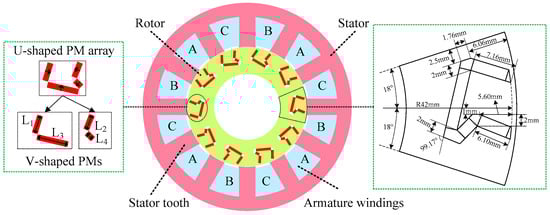
Figure 1.
Structure of the proposed A-PMVM.
The proposed motor belongs to the category of field-modulated motors, whose working principles are typically analyzed using the magnetomotive force (MMF)-permeance model [29].
Firstly, the MMF generated by these irregular U-shaped magnet arrays in the air gap can be represented as
where represents the MMF generated by irregular U-shaped magnet arrays unaffected by the stator teeth. Fh is the amplitude of the h-th harmonic MMF. Pr is the pole-pair number (PPN) of the magnetic field formed by the irregular U-shaped magnet arrays. is the mechanical angular speed of the rotor. is the initial angle of the magnetomotive force.
Secondly, the field modulation effect induced by the slotted stator arises primarily from the significant difference in magnetic permeability between stator teeth and slots. The air-gap permeance () caused by an open-slot stator can be expressed as
where denotes the DC component of the air-gap permeance, represents the amplitude of the k-th harmonic of the air-gap permeance, is the number of the stator teeth, and is the initial angle of the air-gap permeance.
Thirdly, the MMF is modulated by the slotted stator into multiple magnetic field harmonics. These magnetic field harmonics are calculated as the product of the magnetomotive force and the air-gap permeance. Neglecting higher-order harmonics of the MMF and air-gap permeance, the expression for the magnetic field harmonics is given by
where denotes the air-gap flux density generated by the U-shaped magnet arrays under the field modulation effect of the slotted stator [30,31].
It can be seen from Equation (3) that (I) the PPN of the air-gap flux density harmonic in the first term is Pr, which matches that of the magnetic field generated by the irregular U-shaped magnet arrays. The rotational speed of this harmonic is , identical to the rotor speed. (II) The PPN of the air-gap flux density harmonic in the second term is , which differs from that of the magnetic field generated by the magnet arrays. The rotational speed of this harmonic is , unequal to the rotor speed. (III) The PPN of the air-gap flux density harmonic in the third term is , which also differs from that of the magnetic field generated by the magnet arrays. The rotational speed of this harmonic is , likewise unequal to the rotor speed.
To achieve stable electromagnetic torque by matching the armature magnetic field, the PPN of the armature windings (Ps) in PMVMs is designed to be
Thus, the PPN of the armature windings (Ps) in the proposed A-PMVM is designed to be
and the rotational speed of the armature magnetic field must comply with the following condition:
It can be seen from Equation (5) that the PPN of the armature windings in PMVMs differs from that of the magnetic field generated by the magnet arrays. From Equation (6), it is observed that the rotor speed is unequal to the rotational speed of the armature magnetic field, exhibiting a gear-like speed transmission ratio.
Additionally, for 3-phase A-PMVMs, the pole-pair number of the armature windings and stator slot number must satisfy the following condition to accommodate the armature windings within the stator slots [32,33].
where GCD denotes the greatest common divisor.
3. Analysis of Electromagnetic Performance
In this paper, a 3-phase 12/10 (/) A-PMVM is selected for electromagnetic performance analysis. Based on Equation (5), the PPN of the armature windings (Ps) is 2. The basic parameters are listed in Table 1, the rotor’s dimensional specifications are clearly marked in Figure 1, and the connection of the 3-phase armature windings is shown in Figure 2. Two-dimensional (2D) finite element (FE) analysis is performed in JMAG software (Version 23). The FE results are as follows:

Table 1.
Basic parameters of A-PMVM.
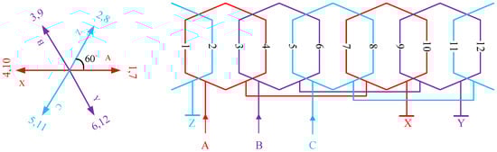
Figure 2.
Winding connection of the A-PMVM.
Figure 3 shows the waveform of the air-gap flux density generated by the U-shaped magnet arrays and its harmonic spectrum. Evidently, the waveform in Figure 3a contains significant harmonic components due to the field modulation effect (FME) of the slotted stator. As observed in Figure 3b, the air-gap flux density harmonic with PPN = 10 exhibits the highest amplitude, which is attributed to the magnetic field generated by the irregular U-shaped magnet arrays having a PPN of 10. Here, 10 corresponds to the PPN of the harmonic in the first term of Equation (3). PPN = 22 and 2 correspond to the harmonic pole-pair numbers in the second and third terms of Equation (3), respectively.
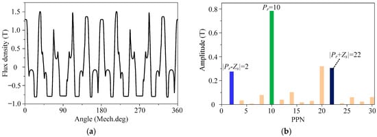
Figure 3.
Air-gap flux density generated by irregular U-shaped magnet arrays. (a) Waveform. (b) Spectrum.
Figure 4 depicts the waveform of the air-gap flux density generated by armature currents and corresponding harmonic spectrum. As can be seen from Figure 4a, the magnetic field generated by the armature currents also contains rich harmonic components due to the FME of the slotted stator. Figure 4b demonstrates that the air-gap flux density harmonic with PPN = 2 exhibits the highest amplitude, which is attributed to the armature windings having a PPN of 2. The torque can be generated by the interaction between the air-gap flux density harmonic with PPN = 2 and the harmonic of the same PPN produced by the magnet arrays. As further observed in Figure 4b, the armature magnetic field, modulated by the slotted stator, generates air-gap flux density harmonics with PPN = 10, which also contribute to torque production via interaction with the 10-pole-pair harmonics from the magnet arrays. It can be concluded that the proposed motor primarily relies on the synergistic interaction of magnetic field harmonics for torque generation. Unlike conventional permanent magnet synchronous motors (PMSMs), they predominantly depend on the fundamental magnetic field to produce torque.
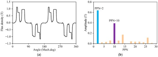
Figure 4.
Air-gap flux density generated by armature currents. (a) Waveform. (b) Spectrum.
Cogging torque serves as a critical indicator for evaluating the torque performance of an electric motor. Since the proposed A-PMVM belongs to the category of PMVMs, its cogging torque period is determined by the following equation [34]:
where LCM represents the least common multiple. Thus, substituting the values of and from Table 1 into Equation (8) yields a cogging torque period of 6° for the proposed A-PMVM. In the FE simulation model established using JMAG software, the rotor speed was set to 300 r/min with a time step of 0.1 ms and simulation duration of 20 ms, yielding the cogging torque waveform shown in Figure 5. Clearly, the period obtained through FE simulation is also 6°, which is consistent with the result obtained by Equation (8). Moreover, the peak-to-peak value is about 0.32 N·m.
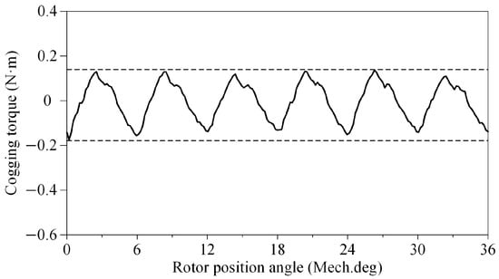
Figure 5.
Waveform of cogging torque.
In the FE simulation model established using JMAG software, the 3-phase armature windings were configured as open-circuit. With the rotor speed set to 300 r/min, a time step of 0.4 ms, and simulation duration of 20 ms, the waveform of the resulting no-load back-electromotive force (Back-EMF) and corresponding harmonic spectrum are presented in Figure 6. At this speed, the no-load Back-EMF waveform demonstrates a period of 20 ms and an amplitude of 116.86 V, corresponding to a fundamental frequency of 50 Hz. Based on the harmonic amplitudes in Figure 6b and the definition of total harmonic distortion (THD), the calculated THD value considering harmonics up to the 32nd order is 4.58%.
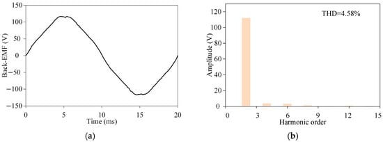
Figure 6.
No-load Back-EMF at the speed of 300 r/min. (a) Waveform. (b) Spectrum.
Blocking torque is used to evaluate the torque output capability of an electric motor. Figure 7 shows the blocking torque waveform over one electrical cycle under rated phase current, which is obtained through FEA in JMAG software. As can be seen, at t = 5.6 ms corresponding to a current phase angle of 101°, the blocking torque reaches its maximum value of 19 N·m, indicating the maximum torque output of the A-PMVM under the rated phase currents.
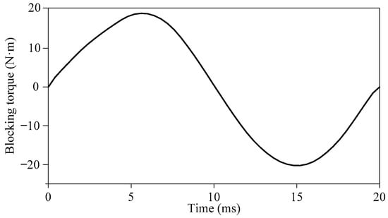
Figure 7.
Waveform of blocking torque at the speed of 0 r/min (Im = 4 A).
Based on the FE model for blocking torque simulation, with the rotor speed set to 300 r/min, current amplitude to 4 A, current frequency to 50 Hz, and current phase angle to 101°, the electromagnetic torque waveform presented in Figure 8 was obtained. Since both current and rotor speed are at rated values, the torque in Figure 8 essentially defines the rated output torque of the proposed A-PMVM. It can be observed that the average torque and the torque ripple ratio are19.67 N·m and 8.65%, respectively. Figure 9 presents the flux lines generated by the combined action of the armature magnetic field and PM field under rated output torque. The zoomed-in area clearly shows one flux envelope. Evidently, the total number of flux envelopes is four. This indicates that despite the PMs having 10 pole-pairs, the armature and PM fields collectively exhibit an equivalent 2 pole-pairs due to FME by the slotted stator. This phenomenon aligns with the field modulation effect in regular PMVMs.
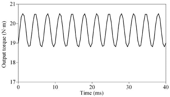
Figure 8.
Waveform of electromagnetic torque at the rated speed of 300 r/min (Im = 4 A).
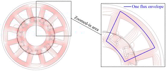
Figure 9.
Flux lines at rated output torque.
Based on the rated speed and average torque, the rated power of the A-PMVM is about 618 W. Additionally, Table 2 presents the losses of the proposed A-PMVM at rated condition. When mechanical losses and stray losses are neglected, the efficiency (η) is calculated as follows [35]:
where Ta denotes average torque, represents the mechanical angular speed of the rotor. Pcu, Piron and PPM correspond to copper loss, iron loss, and eddy loss of PMs, respectively. Substituting Ta =19.67 N·m and rad/s along with the loss data from Table 2 into Equation (9), the efficiency of the proposed A-PMVM under rated condition yields 93%.
Table 2.
The losses of the proposed A-PMVM at rated condition.
The phase inductance (L), including both self-inductance and mutual inductance, can be calculated by the following expression [36]:
where I denotes the current in the phase winding; is the resultant magnetic flux produced by the combined excitation of the current and PMs; and represents the magnetic flux solely generated by the PMs.
With the help of JMAG software, the magnetic flux () produced jointly by PMs and the phase current of 4 A is first obtained via 2D FEA. To account for the saturation effects of stator and rotor cores, the frozen permeability method is then employed to derive magnetic flux () produced solely by PMs. Finally, the phase inductance at rated current (Im = I = 4 A) is calculated according to Equation (10), as illustrated in Figure 10. As can be seen, the average values of the self-inductance and mutual-inductance are 112 mH and 8 mH, respectively. Based on the phase inductances and Park transformation, the d-axis inductance (Ld) and q-axis inductance (Lq) are derived as shown in Figure 11. The figure indicates values of 127 mH and 105 mH for the d-axis and q-axis inductances, respectively.
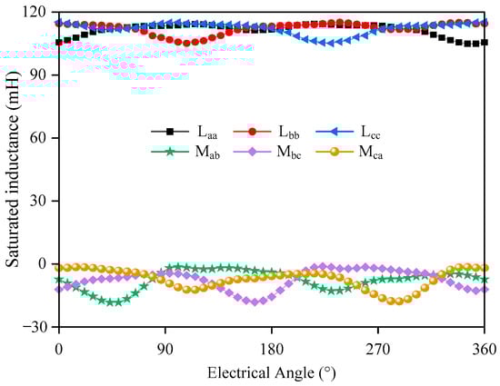
Figure 10.
Phase inductance at rated current (Im = I = 4 A). Self-inductance: Laa, Lbb, Lcc; mutual-inductance: Mab, Mbc, Mca.
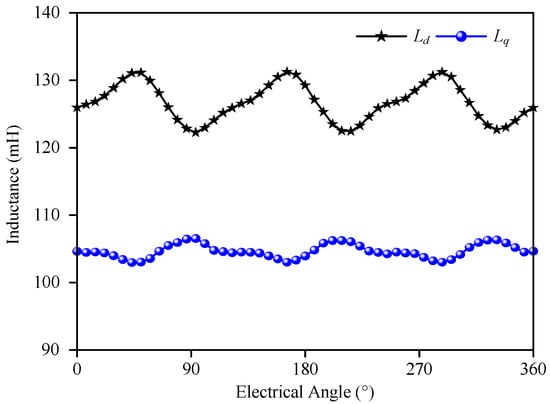
Figure 11.
d-axis inductance (Ld) and q-axis inductance (Lq).
Power factor (PF) serves as a critical performance indicator for motor evaluation, calculable through the following expression [35]:
where E0 denotes the RMS value of Back-EMF; represents the RMS value of phase current; Ra signifies the per-phase winding resistance; corresponds to the mechanical angular speed of the rotor; Lq stands for q-axis inductance. Thus, substituting E0= V, Ra =1.3 Ω, A, Pr=10, rad/s along with Lq = 0.105 H into Equation (11), the PF of the proposed A-PMVM under rated condition yields 0.68.
Figure 12 illustrates the torque output under different phase currents. When the current is below the rated amplitude, the torque output is proportional to the current, whereas when the current exceeds the rated amplitude, the torque ceases to scale linearly with the current due to saturation of the stator and rotor cores. Through linear-region characteristic curve analysis, the motor’s torque constant is established as 4.6 N·m/A.
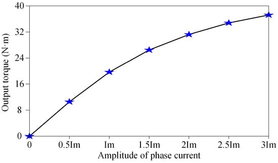
Figure 12.
Torque output under different phase currents at the rated speed of 300 r/min.
Due to the irregular U-shaped magnet array of the proposed A-PMVM, the rotor exhibits an asymmetric structure. It is crucial to investigate the operational consistency of an electric motor with asymmetric structure under both rotation conditions. The following presents the results obtained from the FEA performed using the JMAG software. It should be noted that the counterclockwise rotation direction is set as positive in JMAG software.
Figure 13 shows a comparison of the cogging torque waveforms under clockwise rotation (−300 r/min) and counterclockwise rotation (300 r/min). The waveforms exhibit striking similarity, with the counterclockwise rotation cogging torque measuring 3.2 N·m peak-to-peak and the clockwise rotation cogging torque measuring 0.31 N·m peak-to-peak.
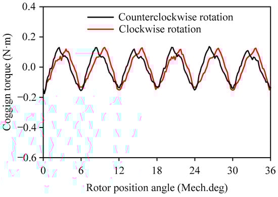
Figure 13.
Waveforms of the cogging torque under clockwise and counterclockwise rotation.
Figure 14 and Figure 15 display waveforms of PM flux-linkage and Back-EMF under clockwise rotation (−300 r/min) and counterclockwise rotation (300 r/min). These figures demonstrate that counterclockwise rotation produces A-B-C phase sequencing (120 electrical degrees apart) for both the PM flux linkage and Back-EMF waveforms, while clockwise rotation results in a reversed A-C-B sequence, as expected. Furthermore, the amplitudes of both the PM flux linkage and Back-EMF remain virtually identical under both rotational directions.
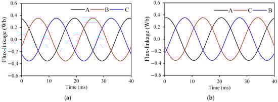
Figure 14.
Waveforms of PM flux-linkage. (a) 300 r/min. (b) −300 r/min.
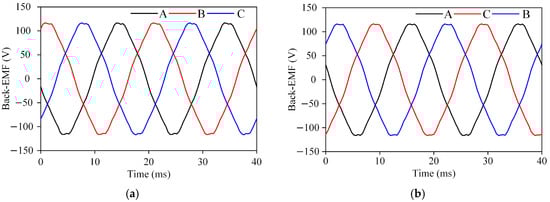
Figure 15.
Waveforms of Back-EMF. (a) 300 r/min. (b) −300 r/min.
Figure 16 shows a comparison of the blocking torque waveforms under clockwise and counterclockwise rotation. It should be noted that the blocking torque for counterclockwise rotation is obtained with the rotor speed set to zero while applying balanced 3-phase currents (4 A amplitude, 50 Hz frequency, 0° initial phase angle, 120° electrical phase separation) in A-B-C sequence. Conversely, the blocking torque for clockwise rotation is obtained under identical excitation conditions but with phase sequence reversed to A-C-B. As can be seen from Figure 16, both curves exhibit essentially identical amplitudes and periods.
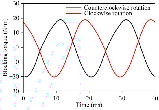
Figure 16.
Waveforms of blocking torque under clockwise and counterclockwise rotation.
According to Figure 16, the times corresponding to the maximum blocking torque during counterclockwise and clockwise rotation are 11.2 ms and 18.8 ms, respectively, with corresponding current phase angles of 202° and 338.4°. Based on the finite element models for the blocking torque waveforms in Figure 16, the output torque waveforms under counterclockwise and clockwise rotation are obtained as shown in Figure 17. Specifically, in the finite element model for blocking torque under counterclockwise rotation, the rotor speed was set to 300 r/min, the current amplitude to 4 A, the current frequency to 50 Hz, and the current phase angle to 202°. In the finite element model for blocking torque under clockwise rotation, the rotor speed was set to −300 r/min, the current amplitude to 4 A, the current frequency to 50 Hz, and the current phase angle to 338.4°. As can be seen from Figure 17, the torque waveforms show close agreement, with counterclockwise rotation exhibiting 19.6656 N·m average output torque and 8.66% torque ripple ratio, while clockwise rotation yields 19.6742 N·m average output torque and 8.70% torque ripple ratio. According to rotor speed and average output torque, the power of the A-PMVM is about 618 W. Additionally, Table 1 presents the losses under clockwise and counterclockwise rotation. It can be observed from Table 3 that the losses and efficiency exhibit virtually identical values under both rotational directions.
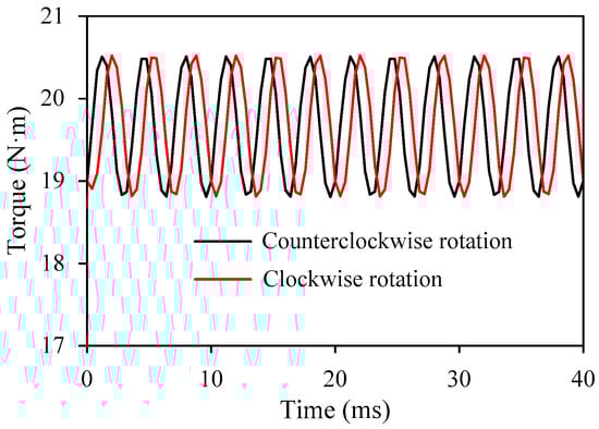
Figure 17.
Waveforms of output torque under clockwise and counterclockwise rotation.
Table 3.
Other performance during clockwise and counterclockwise rotation.
To investigate the proposed motor’s performance under different speeds and operating conditions, torque–speed curves and power–speed curves under both clockwise and counterclockwise rotation are obtained through FEA in JMAG software, as shown in Figure 18. It can be observed from these curves that the proposed A-PMVM maintains consistent performance during both clockwise and counterclockwise rotation.
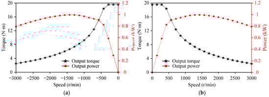
Figure 18.
Torque–speed and power–speed curves. (a) Clockwise rotation. (b) Counterclockwise rotation.
4. Comparative Analysis
Numerous studies have demonstrated that the symmetric V-shaped permanent magnet Vernier motor (SV-PMVM) possesses commendable torque output capability [37,38]. Therefore, this paper selects it for comparative analysis with the proposed A-PMVM. Figure 19 illustrates the structure of the two PMVMs for comparison. It should be noted that the PM volume of A-PMVM in Figure 19 is less than that of SV-PMVM in Figure 19, with volumes of 37,500 mm3 and 48,000 mm3, respectively. Apart from this, both PMVMs share identical stator, winding connection, and key parameters per Table 1 and Table 4.
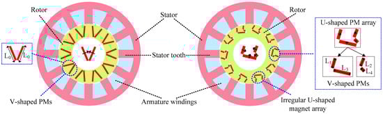
Figure 19.
Structure of two PMVMs for comparison. (left) SV-PMVM. (right) A-PMVM.
Table 4.
Supplementary parameters of SV-PMVM and A-PMVM.
Figure 20 compares the air-gap flux density generated by the PMs in the two PMVMs. The waveforms (Figure 20a) reveal that, under the FME of identical slotted stators, both PMVMs exhibit significant harmonic components. Furthermore, due to the irregular U-shaped magnet arrays in the A-PMVM being composed of asymmetric V-shaped PMs, the maximum and minimum values of its air-gap flux density demonstrate asymmetry. From their harmonic spectra (Figure 20b), it can be observed that since both PMVMs have a pole-pair number of 10, both PMVMs exhibit air-gap flux density harmonics with the maximum amplitude and a pole-pair number of 10. Under the FME of the slotted stators, the magnetic fields generated by the PMs in both PMVMs also contain harmonic components with PPN = 2, matching the pole-pair number of the armature windings to generate torque. Notably, the amplitude of air-gap flux density harmonic with PPN = 10 generated by PMs in the A-PMVM is smaller than that of the harmonic in the SV-PMVM, while the amplitude of air-gap flux density harmonic with PPN = 2 generated by PMs in the A-PMVM is larger than that of the harmonic in the SV-PMVM.
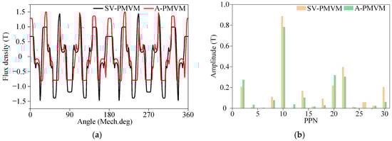
Figure 20.
Air-gap flux density generated by PMs. (a) Waveforms. (b) Spectra.
Figure 21 presents the air-gap flux density generated by the armature currents in the two PMVMs. It should be noted that the results in Figure 21 were obtained through transient FEA. Specifically, in JMAG’s transient field module for both the PMVMs, permanent magnet materials were replaced with air; rotor speed was set to 300 r/min; 3-phase armature windings were excited with symmetric currents of identical amplitude (Im = 4 A), frequency (50 Hz), and initial phase angle (0°); the simulation time step and duration were configured to 0.4 ms and 0.04 s, respectively; and, finally, the results presented in Figure 21 correspond to the first solution step at t = 0 ms. Based on the waveforms in Figure 21a, it can be observed that under the same current amplitude (Im = 4 A), the armature magnetic fields of both PMVMs also contain rich harmonics due to the influence of slotted stators. Differing in performance, the armature magnetic field of the A-PMVM is significantly stronger than that of the SV-PMVM. The spectra in Figure 21b reveal that both PMVMs exhibit a maximum-amplitude air-gap flux density harmonic with PPN = 2, as their 3-phase armature windings are wound for a 4-pole configuration. Similarly, under the FME of the slotted stators, the armature magnetic fields in both PMVMs also contain harmonic components with PPN = 10, matching the pole-pair number of the PMs to generate torque. The spectra also reveal that the amplitudes of the air-gap flux density harmonics with PPN = 2 and PPN = 10 generated by armature currents in the A-PMVM are visibly larger than those in the SV-PMVM.
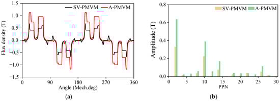
Figure 21.
Air-gap flux density generated by armature currents (Im = 4 A). (a) Waveforms. (b) Spectra.
Figure 22 presents the magnetic field distributions corresponding to Figure 21, including both flux line plots and magnetic field contours. As can be seen from the flux line plots, the presence of four flux envelope loops in both PMVMs indicates identical 4-pole fundamental armature fields (PPN = 2), attributable to identical stator configurations (geometric dimensions, PPN of armature windings, connection of armature windings) and equivalent phase currents. Given identical slotted stator topologies, both PMVMs exhibit essentially equivalent harmonic pole-pair numbers in their armature fields under the field modulation effect of slotted stators. However, the rotor structures differ: the proposed A-PMVM features irregular U-shaped slots, whereas SV-PMVM has V-shaped slots. These distinct rotor slot shapes result in different magnetic flux paths within the rotor. Comparing the color distribution in the magnetic field contours, it is readily apparent that the irregular U-shaped slots significantly enhance the armature field. Additionally, for SV-PMVM, the yoke thickness is minimized with the aim of reducing magnetic leakage flux from the V-shaped magnets in the rotor yoke. This, however, leads to magnetic leakage flux in the yoke region for the armature field. In summary, this explains why, despite having identical stator structures, the proposed A-PMVM exhibits a notably stronger armature field compared to SV-PMVM.
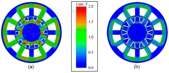
Figure 22.
Magnetic field distributions generated by armature currents. (a) A-PMVM. (b) SV-PMVM.
Figure 23 compares the Back-EMFs when the two PMVMs operate at 300 r/min. As can be seen from Figure 23a, since the two PMVMs share the same slot-pole combination and rotor speed, their Back-EMFs exhibit identical periods of 20 ms. However, as can be seen from Figure 23b, the amplitude of the fundamental Back-EMF of the A-PMVM is higher than that of the SV-PMVM, and the THD of the Back-EMF in the A-PMVM is significantly lower than that in the SV-PMVM, with corresponding THD values of 4.58% and 10.85%, respectively.
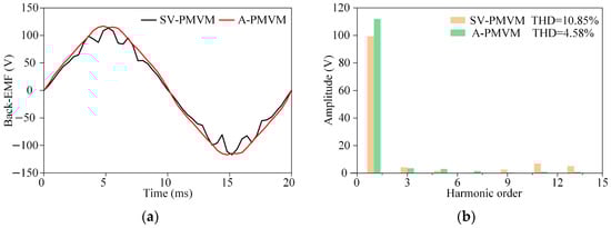
Figure 23.
Back-EMF (300 r/min). (a) Waveforms. (b) Spectra.
Figure 24 compares the cogging torque waveforms of the two PMVMs. The A-PMVM shows a peak-to-peak value of 0.32 N·m, while the SV-PMVM reaches 0.68 N·m. Furthermore, Figure 25 indicates that the rated output torques of the A-PMVM and SV-PMVM are 19.67 N·m and 17.78 N·m, respectively. Consequently, the peak-to-peak cogging torque of the A-PMVM represents 1.63% of its rated output torque, while the corresponding value for the SV-PMVM constitutes 3.82%. Evidently, this demonstrates that asymmetric structures can reduce the cogging torque of electric motors, which aligns with conclusions documented in the literature [39].
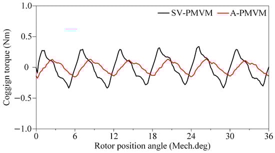
Figure 24.
Cogging torque waveforms of A-PMVM and SV-PMVM.
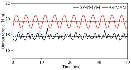
Figure 25.
Output torque curves under rated current and rated speed.
Figure 25 compares the torque of two PMVMs under rated current and rated speed. It is evident that A-PMVM exhibits a significantly higher output torque than SV-PMVM, with corresponding values of 19.67 N·m and 17.78 N·m, respectively. However, A-PMVM demonstrates a slightly larger torque ripple ratio compared to SV-PMVM, registering 8.65% and 7.06%, respectively. According to the magnet volume, motor volume, and motor mass provided in Table 4, the calculated torque-to-magnet-volume ratio, torque-to-motor-volume ratio, and torque-to-motor-mass ratio of A-PMVM are 530 N·m/L, 16.5 N·m/L, and 2.58 N·m/kg, respectively, whereas those of SV-PMVM are 370 N·m/L, 14.9 N·m/L, and 2.32 N·m/kg. The rated-condition losses obtained through 2D FEA are presented in Table 5. Substituting these losses into Equation (9) yields calculated efficiencies of 93.0% for the A-PMVM and 93.5% for the SV-PMVM. Correspondingly, the rated power factors are 0.68 and 0.73, respectively. Clearly, despite minor compromises in torque ripple, efficiency and power factor, the A-PMVM exhibits significantly higher torque output relative to magnet usage, motor volume, and total motor mass compared to the SV-PMVM.
Table 5.
The losses of two machines at rated condition.
5. Multi-Objective Optimization
As evidenced by the comparative analysis above, with lower PM consumption, A-PMVM exhibits a larger output torque yet smaller cogging torque than SV-PMVM. However, A-PMVM demonstrates a higher torque ripple ratio. Therefore, this section conducts multi-objective optimization on the A-PMVM by virtue of JMAG software, aiming to further enhance its output torque while minimizing torque ripple. Figure 26 illustrates the schematic diagram of the optimization parameters for A-PMVM. The ranges of these optimization parameters are listed in Table 6. It should be noted that during the optimization process, the outer radius of stator, inner radius of rotor, and stack length are kept unchanged—meaning the multi-objective optimization is performed while maintaining a constant active volume.
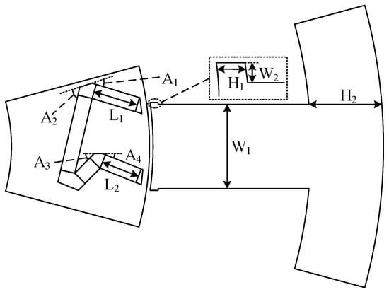
Figure 26.
Schematic diagram of the optimization parameters for A-PMVM.
Table 6.
Ranges of optimization parameters for A-PMVM.
To minimize cogging torque and torque ripple while enhancing output torque, the optimization objectives are written as
where Tave is the output torque, Trip is the torque ripple ratio, and Tcogging is the peak-to-peak value of the cogging torque. Note that throughout the optimization process, the current amplitude is 4 A and the speed of the A-PMVM is 300 r/min.
To reduce experimental iterations and computational complexity, this study employs a hierarchical optimization strategy, with the optimization flowchart illustrated in Figure 27. The optimization procedure is as follows: first, establish a parametric geometric model in JMAG’s built-in Geometry Editor; next, quantitatively analyze the parameter sensitivity of the optimization objectives based on the parametric model; then, categorize the parameter sensitivity into high-sensitivity level (first level) and low-sensitivity level (second level); subsequently optimize high-sensitivity parameters using a genetic algorithm, while optimizing low-sensitivity parameters via parameter sweep; finally, compare pre- and post-optimization results to validate whether the optimization goals are achieved. It should be noted that JMAG is a professional electromagnetic field simulation software developed by JSOL Corporation and creating a parametric geometric model with the built-in Geometry Editor is highly efficient. This is because Geometry Editor offers a comprehensive set of geometric constraint functions, such as radius constraints, distance constraints, angle constraints, parallel constraints, perpendicular constraints, tangent constraints, concentric constraints with the origin, and fixation constraints. These constraint features enable the rapid creation of models with defined dimensions. Subsequently, a parametric model can be constructed by parameterizing these geometric constraints which involve specific values. Taking W1 in Figure 26 as an example, within the sketch drawn in Geometry Editor, select the upper and lower edges of the stator tooth, first apply a parallel constraint, then apply a distance constraint, which yields a value of 11.59 mm. Finally, defining a parameter W1 = 11.59 completes the parameterization of the stator tooth width. For complex geometric configurations, such as the irregular U-shaped magnetic array in Figure 26, auxiliary lines or reference lines (shown as dashed lines in the figure) can be introduced to facilitate geometric relationship constraints and parameterization. For JMAG software, the auxiliary or reference lines introduced in Geometry Editor are only visible in the sketch and are not displayed in the resulting simulation model, because the simulation model only shows the generated regions.
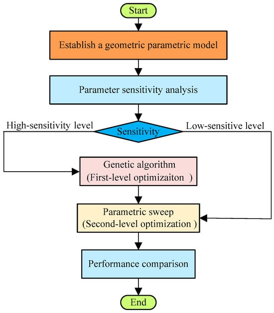
Figure 27.
Flowchart of multi-objective optimization.
Figure 28 illustrates the sensitivity of the optimization objectives (Tave, Trip, Tcogging) to ten optimization parameters in Table 6. As indicated in Figure 28, the sensitivities of Tave, Trip and Tcogging to parameters (A1, A2, A3, H2, W1 and W2) exceed 0.11. Consequently, A1, A2, A3, H2, W1 and W2 are classified as high-sensitivity parameters, whereas the remaining parameters (A4, L1, L2, H1) are low-sensitivity parameters. The high-sensitivity parameters (A1, A2, A3, H2, W1, W2) serve as the first-level optimization variables and undergo NSGA-II optimization by using JMAG software. Subsequently, leveraging the Pareto-optimal solutions from this multi-objective NSGA-II analysis, low-sensitivity parameters (A4, L1, L2, H1) are designated as second-level optimization variables for parametric sweep optimization. Figure 29 displays the multi-objective optimization results for high-sensitivity parameters (first-level optimization). Building upon the first-level optimization results, parametric sweep optimization identified the optimal configuration of A-PMVM, with final parameters detailed in Table 7. As can be seen from Table 7, after optimization, the dimensions of H1 and W2 are still small which may pose challenges for actual prototype manufacturing.
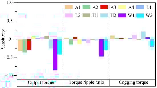
Figure 28.
Result of sensitivity analysis.
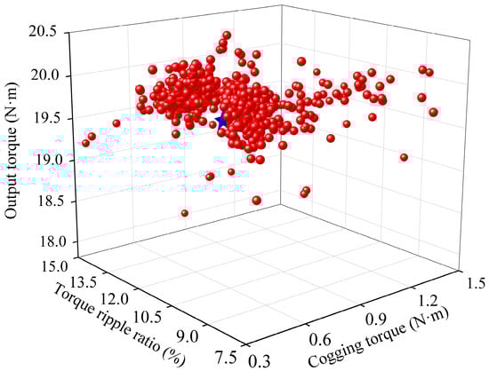
Figure 29.
Multi-objective optimization results for high-sensitivity parameters.
Table 7.
Parameters before and after optimization.
Figure 30 compares the Back-EMF of the A-PMVM at 300 r/min before and after optimization. From Figure 30a, it can be observed that the Back-EMF waveform becomes more sinusoidal after optimization. Figure 30b shows that the fundamental Back-EMF amplitudes before and after optimization are 116.86 V and 118.37 V, respectively, indicating a slight increase after optimization.
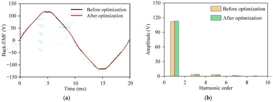
Figure 30.
Back-EMF before and after optimization at 300 r/min. (a) Waveforms. (b) Spectra.
Figure 31a illustrates the output torque waveforms before and after optimization at a phase current of 4 A. It is evident that the output torque has increased 0.76% after optimization, rising from 19.67 N·m to 19.82 N·m. Additionally, the torque ripple ratio after optimization has decreased 5.32%, from 8.65% to 8.19%. Concurrently, Figure 31b presents the cogging torque waveforms before and after optimization. From the figure, it can be seen that the peak-to-peak value of the optimized cogging torque has decreased 12.5% from 0.32 N·m to 0.28 N·m. The peak-to-peak value of cogging torque before and after optimization accounts for 1.63% and 1.41% of the output torque, respectively.
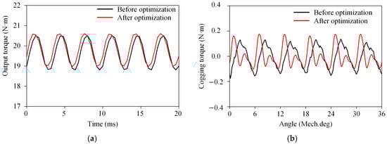
Figure 31.
Torque performance before and after optimization. (a) Output torque. (b) Cogging torque.
Figure 32 compares the magnetic field contour of the A-PMVM before and after optimization under a phase current of 4 A during torque output. Since the stator and rotor cores of the A-PMVM are made of electrical steel grade 50CS400, whose B-H curve has a knee point at a magnetic flux density (B) of 1.5 T, a core is considered saturated when its magnetic flux density is B > 1.5 T, and unsaturated when B < 1.5 T. As indicated by the scale, the yellow and red regions exhibit a magnetic flux density greater than 1.5 T, meaning that these areas represent saturated parts of the core. Observation of the rotor yoke from Figure 32a reveals that localized saturation already occurs in the pre-optimization design. From Figure 32b, it can be observed that the optimized A-PMVM alleviates core saturation primarily by increasing the stator yoke thickness, with a particularly noticeable improvement in mitigating stator core saturation. However, since the rotor inner radius and active volume of the motor are fixed during optimization, although the angles A2 and A3 (Figure 26 and Table 7) are increased to slightly enlarge the rotor yoke thickness, the effect on reducing rotor core saturation is less pronounced. Therefore, during the experimental prototype stage, the rotor yoke will be optimized to reduce the saturation level of the rotor core and further enhance the motor’s performance.
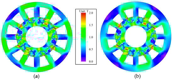
Figure 32.
Magnetic field distributions. (a) Before optimization. (b) After optimization.
6. Conclusions
In this paper, an Asymmetric Permanent Magnet Vernier Motor (A-PMVM) is proposed. Its electromagnetic performance-including air-gap flux density, cogging torque, Back-EMF, and electromagnetic torque-is analyzed by 2D FEA in JMAG software. The results demonstrate operational consistency under both rotational directions. Comparative studies with a conventional symmetric V-shaped PMVM (SV-PMVM) reveal that under reduced PM consumption, the A-PMVM significantly enhances the air-gap flux density generated by armature currents while demonstrating distinct advantages in cogging torque reduction (53% lower peak-peak value) and output torque (10.6% increase). To further improve the torque performance, a multi-objective optimization was implemented, resulting in a 12.5% decrease in cogging torque (from 0.32 N·m to 0.28 N·m), a 5.32% reduction in torque ripple ratio (to 8.19%), alongside a 0.76% increase in torque (from 19.67 N·m to 19.82 N·m). However, it is undeniable that the optimized H1 and W2 are small, which may pose challenges for actual prototype manufacturing. Additionally, the reduction in the core saturation level of the rotor yoke is not very significant. Therefore, during the experimental prototype stage, we will further optimize the rotor yoke to reduce core saturation and enhance the motor’s performance, while taking into account current machining precision limitations.
Author Contributions
Conceptualization, Y.S. and Q.L.; methodology, Q.L. and W.Z.; software, Q.L. and W.Z.; validation, Y.S. and Q.L.; formal analysis, H.L. and J.W.; investigation, Q.L.; resources, Y.L.; data curation, Q.L.; writing—original draft preparation, Q.L.; writing—review and editing, Y.S. and J.W.; visualization, Q.L. and W.Z.; supervision, Y.S. and H.L.; project administration, Y.S.; funding acquisition, Y.S. All authors have read and agreed to the published version of the manuscript.
Funding
This work was supported in part by the Tianchi Talent Projects of Xinjiang Urumqi Autonomous Region of China under Grant 51052401512 and 5105240151s, and in part by the Research Startup Fund for Excellent Talents at Xinjiang University under Grant 620323005 and 620323007.
Data Availability Statement
The original contributions presented in this study are included in the article. Further inquiries can be directed to the corresponding author.
Conflicts of Interest
Author Yaogang Liu was employed by the company Integrated Electronic Systems Lab Co., Ltd. The remaining authors declare that the research was conducted in the absence of any commercial or financial relationships that could be construed as a potential conflict of interest.
References
- Ozdincer, B.; Aydin, M. Design of innovative radial flux permanent magnet motor alternatives with non-oriented and Grain-oriented electrical steel for servo applications. IEEE Trans. Magn. 2022, 58, 1–4. [Google Scholar] [CrossRef]
- Barzkar, A.; Ghassemi, M. Electric power systems in more and all electric aircraft: A Review. IEEE Access 2020, 8, 169314–169332. [Google Scholar] [CrossRef]
- Wu, D.Y.; Xiang, Z.X.; Zhu, X.Y.; Quan, L.; Jiang, M.; Liu, Y. Optimization design of power factor for an In-Wheel vernier PM machine from the perspective of air-gap harmonic modulation. IEEE Trans. Ind. Electron. 2021, 68, 9265–9276. [Google Scholar] [CrossRef]
- Xiang, Z.X.; Wei, J.Q.; Zhu, X.Y. Torque ripple suppression of a PM vernier machine from perspective of time and space harmonic magnetic field. IEEE Trans. Ind. Electron. 2024, 71, 10150–10161. [Google Scholar] [CrossRef]
- Xiang, Z.X.; Zhou, Y.T.; Zhu, X.Y.; Quan, L.; Fan, D.; Liu, Q. Research on characteristic airgap harmonics of a double-rotor flux-modulated PM motor based on harmonic dimensionality reduction. IEEE Trans. Transp. Electrif. 2024, 10, 5750–5761. [Google Scholar] [CrossRef]
- Jia, C.; Ji, J.H.; Ling, Z.J.; Zhao, W.X.; Zeng, Y.; Luo, Z.Y. Mechanism of winding Factor enhancement permanent magnet motor based on non-air-gap side modulation. Proc. CSEE 2025, 45, 1260–1271. [Google Scholar]
- Zhao, F.; Yang, K.; Wang, Y. Design and analysis of a modular permanent magnet vernier machine for electric vehicle application. Proc. CSEE 2021, 41, 332–342. [Google Scholar]
- Gong, C.; Deng, F. Design and optimization of a high-torque-density low-torque-ripple vernier machine using ferrite magnets for direct-drive applications. IEEE Trans. Ind. Electron. 2022, 69, 5421–5431. [Google Scholar] [CrossRef]
- Xu, L.; Wu, W.J.; Zhao, W.X. Airgap magnetic field harmonic synergetic optimization approach for power factor improvement of PM vernier machines. IEEE Trans. Ind. Electron. 2022, 69, 12281–12291. [Google Scholar] [CrossRef]
- Liu, G.H.; Jing, S.; Zhao, W.X.; Chen, Q. A new modeling approach for permanent magnet vernier machine with modulation effect consideration. IEEE Trans. Magn. 2017, 53, 1–12. [Google Scholar] [CrossRef]
- Zhao, Y.; Li, D.; Ren, X.; Qu, R. Investigation of permanent magnet vernier machines from armature field perspective. IEEE J. Emerg. Sel. Top. Power Electron. 2022, 10, 2934–2945. [Google Scholar] [CrossRef]
- Ma, Y.; Xiao, Y.; Wang, J.; Zhou, L. Multicriteria optimal latin hypercube design-based surrogate-assisted design optimization for a permanent-magnet vernier machine. IEEE Trans. Magn. 2022, 58, 1–5. [Google Scholar] [CrossRef]
- Wu, L.L.; Qu, R.H. A novel dual-stator vernier permanent magnet machine with improved power factor. IEEE Trans. Ind. Appl. 2022, 58, 3486–3496. [Google Scholar] [CrossRef]
- Zhao, Y.; Ren, X.; Fan, X.G.; Li, D.; Qu, R. A high power factor permanent magnet vernier machine with modular stator and yokeless rotor. IEEE Trans. Ind. Electron. 2023, 70, 7141–7152. [Google Scholar] [CrossRef]
- Zhang, H.L.; Hua, W.; Gerada, D.; Li, Y.; Zhang, G. Comparative study on two modular spoke-type PM machines for in-wheel traction applications. IEEE Trans. Energy Convers. 2019, 34, 2137–2147. [Google Scholar] [CrossRef]
- Liang, Z.Y.; Ren, X.; Li, D.W.; Qu, R.; Han, X. Analysis of a spoke-array brushless dual-electrical-port dual-mechanical-port machine with reluctance rotor. IEEE Trans. Ind. Electron. 2021, 68, 2999–3011. [Google Scholar] [CrossRef]
- Qu, R.H.; Li, D.W.; Zhao, Y. The origin, development and challenge of flux modulation machine. Proc. CSEE 2024, 44, 7361–7381. [Google Scholar]
- Fang, L.; Qu, R.H.; Li, D.W. Topology orientation construction methodology of high-torque density vernier permanent magnet machine. Proc. CSEE 2025, 45, 1284–1299. [Google Scholar]
- Li, D.W.; Qu, R.H.; Li, J. Topologies and analysis of flux-modulation machines. In Proceedings of the 2015 IEEE Energy Conversion Congress and Exposition, Montreal, QC, Canada, 20–24 September 2015. [Google Scholar]
- Cheng, M.; Han, P.; Hua, W. General airgap field modulation theory for electrical machines. IEEE Trans. Ind. Electron. 2017, 64, 6063–6074. [Google Scholar] [CrossRef]
- Yu, J.C.; Mi, W.Y.; Cai, Z.; Song, Z.; Liu, S.; Liu, C. Design principle considering structural mutual effects of double-stator V-shape-PM vernier machines for electric ship propulsion. IEEE Trans. Transp. Electrific. 2024, 10, 496–508. [Google Scholar] [CrossRef]
- Zhao, G.S.; Hua, W. Comparative study between a novel multi-tooth and a v-shaped flux-switching permanent magnet machines. IEEE Trans. Magn. 2019, 55, 1–8. [Google Scholar] [CrossRef]
- Qu, H.; Zhu, Z.Q. Analysis of spoke array permanent magnet flux reversal machines. IEEE Trans. Energy Convers. 2020, 35, 1688–1696. [Google Scholar] [CrossRef]
- Zhang, Y.W.; Zhao, Y.; Li, D.W.; Qu, R.H. A novel high torque density spoke-array permanent magnets vernier machine with magnets bridge. In Proceedings of the 2023 26th International Conference on Electrical Machines and Systems (ICEMS), Zhuhai, China, 5–8 November 2023. [Google Scholar]
- Zou, T.J.; Li, D.W.; Qu, R.H.; Jiang, D.; Li, J. Advanced high torque density PM vernier machine with multiple working harmonics. IEEE Trans. Ind. Appl. 2017, 53, 5295–5304. [Google Scholar] [CrossRef]
- Fang, L.; Li, D.W.; Ren, X.; Qu, R.H. A novel permanent magnet vernier machine with coding-shaped tooth. IEEE Trans. Ind. Electron. 2022, 69, 6058–6068. [Google Scholar] [CrossRef]
- Li, J.; Wang, K. A novel spoke-type PM machine employing asymmetric modular consequent-pole rotor. IEEE Trans. Mecha-tron. 2019, 24, 2182–2192. [Google Scholar] [CrossRef]
- Zhao, W.X.; Yao, T.; Xu, L.; Chen, X.; Song, X. Multi-objective optimization design of a modular linear permanent-magnet vernier machine by combined approximation models and differential evolution. IEEE Trans. Energy Convers. 2021, 68, 4634–4645. [Google Scholar] [CrossRef]
- Fang, L.; Li, D.W.; Qu, R.H. Torque improvement of vernier permanent magnet machine with larger rotor pole pairs than stator teeth number. IEEE Trans. Ind. Electron. 2023, 70, 12648–12659. [Google Scholar] [CrossRef]
- Li, J.; Yang, G.; Rao, F. Analysis and design of novel axial field flux-modulation permanent magnet machines for direct drive application. Machines 2022, 10, 495. [Google Scholar] [CrossRef]
- Lyeo, M.-G.; Hwang, K.-Y.; Lee, S.-H. Design of dual winding flux modulation machine for performance improvement in vari-able speed application. Machines 2024, 12, 535. [Google Scholar] [CrossRef]
- Qu, H.; Zhu, Z.Q. Analysis of split-tooth stator slot PM machine. IEEE Trans. Ind. Electron. 2021, 68, 10580–10591. [Google Scholar] [CrossRef]
- Afinowi, I.A.A.; Zhu, Z.Q.; Guan, Y.; Mipo, J.-C.; Farah, P. A novel brushless AC doubly salient stator slot permanent magnet machine. IEEE Trans. Energy Convers. 2016, 31, 283–292. [Google Scholar] [CrossRef]
- Guendouz, W.; Tounzi, A.; Rekioua, T. Design of quasi-Halbach permanent-magnet vernier machine for direct-drive urban vehicle application. Machines 2023, 11, 136. [Google Scholar] [CrossRef]
- Li, R.; Shi, C.J.; Qu, R.H.; Li, D.; Ren, X.; Fedida, V. A novel modular stator fractional pole-pair permanent-magnet vernier machine with low torque ripple for servo applications. IEEE Trans. Magn. 2021, 57, 1–6. [Google Scholar] [CrossRef]
- Shi, Y.J.; Cheng, Z.H.; Jian, L.N. Comparative analysis of two typical field modulated permanent-magnet machines. Diangong Jishu Xuebao/Trans. China Electrotech. Soc. 2021, 36, 120–130. [Google Scholar]
- Shi, Y.J.; Lu, H.F.; Wang, J.W.; Du, T.; Liu, Q.; Zhao, W. Design and Analysis of a Field-Modulated Permanent-Magnet Direct-Drive Wind Power Generator with Non-uniform Distribution of V-shaped Magnets. In Proceedings of the 2024 International Conference on HVDC (HVDC), Urumqi, China, 8–9 August 2024; pp. 311–316. [Google Scholar]
- Xiang, Z.X.; Pu, W.L.; Zhu, X.; Quan, L. Design and analysis of a V-Shaped Permanent magnet vernier motor for high torque density. IEEE Trans. Ind. Electron. 2022, 6, 20–28. [Google Scholar] [CrossRef]
- Xie, S.; Lee, C.H.T. A new design concept for permanent magnet vernier machine: Positive-mutual-coupling for improved power factor and higher field-weakening capability. IEEE Trans. Ind. Electron. 2025, 72, 5669–5680. [Google Scholar] [CrossRef]


Disclaimer/Publisher’s Note: The statements, opinions and data contained in all publications are solely those of the individual author(s) and contributor(s) and not of MDPI and/or the editor(s). MDPI and/or the editor(s) disclaim responsibility for any injury to people or property resulting from any ideas, methods, instructions or products referred to in the content. |
© 2025 by the authors. Licensee MDPI, Basel, Switzerland. This article is an open access article distributed under the terms and conditions of the Creative Commons Attribution (CC BY) license (https://creativecommons.org/licenses/by/4.0/).