Article

Stability Enhancement and Bifurcation Mitigation in Nonlinear Inner Plate Oscillations Through PD Control

by
Ashraf Taha EL-Sayed
1,*,
Rageh K. Hussein
2,
Yasser A. Amer
3 and
Marwa A. EL-Sayed
4
1
Department of Basic Science, Modern Academy for Engineering and Technology, Elmokattam, Cairo 11439, Egypt
2
Physics Department, College of Science, Imam Mohammad Ibn Saud Islamic University (IMSIU), Riyadh 11623, Saudi Arabia
3
Department of Mathematics, Faculty of Science, Zagazig University, Zagazig 44519, Egypt
4
Department of Mathematics, High Institute of Computer Science and Information System, Fifth Settlement, Cairo 11835, Egypt
*
Author to whom correspondence should be addressed.
Machines 2025, 13(9), 828; https://doi.org/10.3390/machines13090828 (registering DOI)
Submission received: 12 August 2025 / Revised: 2 September 2025 / Accepted: 5 September 2025 / Published: 8 September 2025

Abstract

Axially moving wings offer remarkable aerodynamic efficiency and adaptability; however, they are highly susceptible to detrimental vibrations that may compromise flight stability and structural integrity. Previous studies have mainly focused on simplified linear models or passive control approaches, leaving the nonlinear dynamic behavior and active vibration suppression insufficiently addressed. To overcome these limitations, this study models the wing as a simplified cantilever plate and investigates its nonlinear dynamics under varying load conditions. A proportional–derivative (PD) controller is employed, and approximate analytical solutions to the governing equations are derived using the multiple-scale perturbation method (MSPM). The system’s response under primary resonance is analyzed through frequency response and bifurcation studies, while stability is assessed using the Routh–Hurwitz criterion. Analytical findings are validated with numerical simulations in MATLAB R2023b. Furthermore, the influence of key structural parameters on system dynamics and controller performance is examined. The results demonstrate that the PD controller effectively suppresses vibrations, offering a reliable solution for enhancing the stability of axially moving wing systems.

1. Introduction

Nonlinear dynamical phenomena in aerospace structures have received considerable attention because understanding them is essential for ensuring structural integrity and flight performance. Zhang et al. [1] investigated the nonlinear dynamics of deploying wings in subsonic airflow, providing important insights into the complex aeroelastic interactions of morphing-wing systems. Sanders et al. [2] presented an overview of the DARPA Smart Materials and Structures Demonstration Program, highlighting the potential of advanced smart structures to improve aerospace performance and reliability. Building on these developments, Lu et al. [3] examined the dynamic stability of axially moving graphene-reinforced laminated composite plates under constant and varying velocities, emphasizing the effect of reinforcement on nonlinear vibration characteristics.
Torres and Mendonça [4] advanced the modeling of smart structures by analyzing piezoelectric laminates using the generalized finite element method and mixed layer-wise higher-order shear deformation theories, offering accurate techniques for modeling electromechanical coupling. More recently, Zhang et al. [5] performed theoretical, numerical, and experimental studies on the time-varying dynamics of telescopic wings, yielding valuable insights into the aeroelastic response of extendable aerospace structures. Liu [6] conducted a nonlinear dynamic analysis of axially moving composite laminated cantilever beams, while Liu and Ma [7] extended this work to composite stepped piezoelectric cantilever plates subjected to aerodynamic loading and external excitation, revealing pronounced nonlinear oscillatory behavior. Beyond structural modeling, considerable research has focused on controller design for vibration suppression. Bauomy and El-Sayed [8] proposed a six-degrees-of-freedom model for a composite plate controlled using a PPF controller, demonstrating the effectiveness of this strategy for vibration mitigation. Li and Laima [9] experimentally investigated nonlinear flutter behavior of bridge decks with varying leading and trailing edges, underscoring the influence of aerodynamic geometry on dynamic stability. Finally, Amer et al. [10] studied a hybrid Rayleigh–Van der Pol–Duffing oscillator under PD control, demonstrating the capability of PD controllers to suppress nonlinear oscillations in complex dynamical systems.
Hamed et al. [11] investigated the vibration performance, stability, and energy transfer of a wind turbine tower controlled by a PD controller. Their findings confirmed the effectiveness of PD control in enhancing system stability under aerodynamic excitations. Similarly, Ren and Ma [12] analyzed the dynamics and control of a twelve-pole active magnetic bearing system, demonstrating the ability of PD control to maintain stability and suppress vibrations in high-speed rotating machinery. Hamed et al. [13] extended this line of research by exploring the nonlinear vibration responses of a vertical conveyor system subjected to PD control, where they confirmed that PD control significantly improves system robustness against dynamic disturbances. Bahnasy et al. [14] examined the stability and bifurcation of a two-degrees-of-freedom system with a piezoelectric device and feedback control, demonstrating the interplay between nonlinear dynamics and active control. Jamshidi and Collette [15] developed optimal negative derivative feedback controllers using H2 and H∞ techniques, while Amer and Abd El-Salam [16] applied a negative derivative feedback controller to a Rayleigh–Van der Pol–Duffing oscillator, confirming its efficiency in vibration suppression. Alluhydan et al. [17] employed a Positive Position Feedback (PPF) controller for generator regulation in hybrid electric vehicles, extending the application of PPF beyond aerospace structures. Bahnasy et al. [18] analyzed chaotic dynamics of quasi-zero stiffness vibration isolators using multiple control methods, emphasizing stability under strong nonlinearities. Hamed et al. [19] investigated nonlinear resonance in a Cartesian manipulator system, and Ngouabo et al. [20] studied electrostatic MEMS resonators with delayed PD control, highlighting the impact of time delay.
Seth et al. [21] explored bifurcations in a two-degrees-of-freedom impacting system, while Alluhydan et al. [22] examined nonlinear integral PPF control for beam flutter phenomena. Nussbaumer et al. [23] developed a modular test rig for in-flight validation of aerodynamic devices, and Taufik et al. [24] analyzed trimmable vertical stabilizers to enhance aircraft maneuverability. Zhu et al. [25] proposed an adaptive feedforward control method for piezoelectric cantilever beams, advancing active vibration control strategies. Kandil et al. [26] applied multiple time-scale analysis to thin-walled beams under resonance, and Saeed et al. [27] investigated active dampers for multistability suppression in a nonlinear rotor model. Fyrillas and Szeri [28] addressed the control of ultra- and subharmonic resonances, while Azimov and Ikhsanova [29] modeled the stability of agricultural machinery on slopes. Kandil et al. [30] studied rotor active magnetic bearings under nonlinear saturation oscillators, and Bauomy [31] developed an active vibration controller for beams subjected to moving loads. Saeed et al. [32] analyzed the stability and bifurcation of a discontinuous rotor model under rub-impact, and Elashmawey et al. [33] extended this to asymmetric rotor systems with mixed excitations, confirming the effectiveness of active control in complex nonlinear settings.
In summary, while previous studies have explored nonlinear dynamics and vibration control in aerospace and mechanical systems using various strategies, the combined effect of axial motion, geometric nonlinearity, and proportional–derivative control has not been rigorously addressed in a unified theoretical framework. The present study contributes to filling this gap by formulating a reduced-order nonlinear model for axially moving wings, applying the multi-scale perturbation method to derive solvability conditions and amplitude evolution equations, and conducting a detailed bifurcation and stability analysis. These results provide new insights into the effectiveness of proportional–derivative control for vibration suppression and offer a solid theoretical foundation for guiding future numerical and experimental investigations.

2. Dynamic Loop Model

2.1. Describe the PD Controller

A proportional–derivative (PD) controller is a sort of feedback control system that enhances a system’s stability and responsiveness. Physically, it consists of two main components:
  • Proportional (P) Control: This controller component generates an output that is proportional to the fault (the difference between the desired and actual outputs). It responds to the current error and helps move the system toward the desired state. However, adopting simply proportional control may cause steady-state errors and oscillations.
  • Derivative (D) Control: This component considers the rate of change (or derivative) of the mistake. It predicts future error patterns and takes corrective action to reduce oscillations and increase system stability. It functions as a “shock absorber” by mitigating fast fluctuations in the error signal, reducing overshoot, and improving transient response.

2.2. Physical Interpretation

A PD controller can be considered equivalent to a spring-damper mechanism. The P term acts like a spring, pulling the system toward the intended location (reference point). The D term functions as a damper, resisting rapid motion and preventing excessive oscillations. In real-world applications, PD controllers are often employed in robotics, motor control, and aerospace systems, where quick and stable responses are required.

2.3. Justification for the Reduced-Order Model

To investigate the essential dynamic behavior of the system, a reduced-order model with two degrees of freedom (2DOF) was adopted. This simplification is based on the assumption that the dominant vibration modes contributing to the internal and principal resonance phenomena can be captured by considering only the translational motion of the main mass and the internal plate. Higher-order modes and out-of-plane deformations were neglected due to their minimal contribution within the frequency range of interest. A preliminary modal analysis confirmed that the first two modes carry the majority of the system’s kinetic and potential energy, thereby justifying the 2DOF approximation. This approach provides a balance between model simplicity and the ability to accurately capture the key nonlinear dynamic features, including internal resonance. Although more complex modeling techniques—such as finite element analysis or higher-mode modal truncation—could offer greater fidelity, the 2DOF model is sufficient for the objectives of this study. It enables analytical tractability and allows for the effective investigation of the nonlinear resonance phenomena without excessive computational complexity.

2.4. Motivation and General Relevance of the Model

Although the current model does not directly represent a specific mechanical system, it serves as a generalized framework for studying fundamental nonlinear dynamic behaviors such as internal resonance and chaotic oscillations. The 2DOF configuration with an inner oscillating component is commonly used in the literature as a simplified prototype to investigate the core mechanisms underlying energy exchange, mode coupling, and control strategies in complex systems. Such models provide valuable insight and are frequently employed as benchmarks in theoretical studies prior to extension to more detailed representations involving flexible structures, fluid–structure interactions, or multi-body systems. Therefore, despite its abstract form, the proposed model captures essential features that are relevant to a wide range of engineering applications, including aerospace structures, mechanical vibration absorbers, and energy harvesting devices.

2.5. System Dynamics Without Control

The derivation of the equation system is concluded in Appendix B.
This section describes the mathematical model of the uncontrolled inner plate [7].
x ¨ + ω 1 2 x + ε μ 1 x ˙ + ε f 11 cos Ω 1 t + f 12 cos Ω 2 t + f 13 cos Ω 3 t x + ε α 1 x 2 y + ε α 2 x y 2 + ε α 3 x 3 + ε α 4 y 3 = ε f 1 cos Ω 4 t .
y ¨ + ω 2 2 y + ε μ 2 y ˙ + ε f 21 cos Ω 1 t + f 22 cos Ω 2 t + f 23 cos Ω 3 t y + ε β 1 y 2 x + ε β 2 x 2 y + ε β 3 y 3 + ε β 4 x 3 = ε f 2 cos Ω 4 t .

2.6. System Dynamics with Control

After adding PD control, engineers frequently use simplified models to analyze the behavior of inner plate systems. A proportional–derivative (PD) feedback controller can dampen vibrations caused by external forces acting on the system.
x ¨ + ω 1 2 x + ε μ 1 x ˙ + ε f 11 cos Ω 1 t + f 12 cos Ω 2 t + f 13 cos Ω 3 t x + ε α 1 x 2 y + ε α 2 x y 2 + ε α 3 x 3 + ε α 4 y 3 = ε f 1 cos Ω 4 t ε λ 1 x + λ 2 x ˙ .
y ¨ + ω 2 2 y + ε μ 2 y ˙ + ε f 21 cos Ω 1 t + f 22 cos Ω 2 t + f 23 cos Ω 3 t y + ε β 1 y 2 x + ε β 2 x 2 y + ε β 3 y 3 + ε β 4 x 3 = ε f 2 cos Ω 4 t ε λ 3 y + λ 4 y ˙ .
Equations (3) and (4) describe the structure’s performance in these states, integrating the effects of both the harmonic force and the PD controller. To facilitate the analysis, the physical system is simplified and represented as a two-degrees-of-freedom model, as illustrated in Figure 1. The inner plate is considered to move axially along the x-direction with constant speed, while undergoing transverse vibrations in both x and y directions. The structure is subjected to external aerodynamic excitations denoted by a combination of steady and oscillatory pressure components (Δp), which act on the flexible surface of the plate. The PD controller, as shown in the block diagram of Figure 1, receives feedback signals from the vibration responses (x, y), processes them through proportional and derivative gains, and generates actuation forces to suppress undesired vibrations. The mathematical formulation of this control mechanism is integrated into the governing equations.

3. Mathematical Investigation

3.1. Perturbation Study

This section uses the multiple time-scale technique (MTST) to establish an approximate analytical solution for the nonlinear dynamic system controlled by the suggested proportional–derivative (PD) controller. This approach yields a first-order approximation, which provides useful insights into the system’s dynamic behavior under primary resonance conditions [34,35,36]. The governing equations of motion are developed using the simplified cantilever plate model, and the control forces produced by the PD regulator are clearly included. The derivation methodology, assumptions, and perturbation techniques used are well described, providing reproducibility and methodological transparency. Furthermore, numerical simulations are used to confirm the analytical conclusions, reinforcing the trustworthiness and suitability of the described technique.
t = T 0 + T 1 + , x ( t ; ε ) = x 0 ( T 0 , T 1 ) + ε x 1 ( T 0 , T 1 ) + O ( ε 2 ) , y ( t ; ε ) = y 0 ( T 0 , T 1 ) + ε y 1 ( T 0 , T 1 ) + O ( ε 2 ) .
where the wild ruler is T 0 and the leisurely ruler is T 1 = ε t . The offshoots via the MTST income are the following formulae:
d d t = D 0 + ε D 1 + ε 2 D 2 + , d 2 d t 2 = D 0 2 + 2 ε D 0 D 1 + ,      D j = T j    ( j = 0 , 1 ) .
inserting Equations (5) and (6) into Equations (3) and (4) such that
D 0 2 + ω 1 2 x 0 + ε D 0 2 + ω 1 2 x 1 = ε λ 1 x 0 λ 2 D 0 x 0 2 D 0 D 1 x 0 μ 1 D 0 x 0 α 1 x 0 2 y 0 α 2 y 0 2 x 0 α 3 x 0 3 α 4 y 0 3 f 11 cos Ω 1 t + f 12 cos Ω 2 t + f 13 cos Ω 3 t x 0 + f 1 cos Ω 4 t + O ε 2
D 0 2 + ω 2 2 y 0 + ε D 0 2 + ω 2 2 y 1 = ε λ 3 y 0 λ 4 D 0 y 0 2 D 0 D 1 y 0 μ 2 D 0 y 0 β 1 y 0 2 x 0 β 2 x 0 2 y 0 β 3 y 0 3 β 4 x 0 3 f 21 cos Ω 1 t + f 22 cos Ω 2 t + f 23 cos Ω 3 t y 0 + f 2 cos Ω 4 t + O ( ε 2 )
associating the terms of the equal power of ε
O ε 0
D 0 2 + ω 1 2 x 0 = 0
D 0 2 + ω 2 2 y 0 = 0
O ε 1
D 0 2 + ω 1 2 x 1 = f 1 cos Ω 4 t λ 1 x 0 λ 2 D 0 x 0 2 D 0 D 1 x 0 μ 1 D 0 x 0 α 1 x 0 2 y 0 α 2 y 0 2 x 0 f 11 cos Ω 1 t + f 12 cos Ω 2 t + f 13 cos Ω 3 t x 0 α 3 x 0 3 α 4 y 0 3
D 0 2 + ω 2 2 y 1 = f 2 cos Ω 4 t λ 3 y 0 λ 4 D 0 y 0 2 D 0 D 1 y 0 μ 2 D 0 y 0 β 1 y 0 2 x 0 β 2 x 0 2 y 0 f 21 cos Ω 1 t + f 22 cos Ω 2 t + f 23 cos Ω 3 t y 0 β 3 y 0 3 β 4 x 0 3
from Equations (9) and (10). Solving the homogeneous differential equations, we obtain
x 0 ( T 0 , T 1 ) = A ( T 1 )   e i ω 1 T 0 + A ¯ ( T 1 )   e i ω 1 T 0
y 0 ( T 0 , T 1 ) = B ( T 1 )   e i ω 2 T 0 + B ¯ ( T 1 )   e i ω 2 T 0
Substituting Equations (13) and (14) into Equations (11) and (12) yields
D 0 2 + ω 1 2 x 1 = 2 i   ω 1 D 1 A λ 1 A λ 2 i   ω 1 A 3 α 3 A 2 A ¯ μ 1 i   ω 1 A 2 α 2 B B ¯ A e i ω 1 T 0 + f 1 2 e i Ω 4 T 0 2 α 1 A A ¯ B + 3 α 4 B 2 B ¯ e i ω 2 T 0     α 1 A 2 B   e i 2 ω 1 + ω 2 T 0   α 1 A ¯ B 2   e i 2 ω 2 ω 1 T 0 α 3 A 3 e 3 i ω 1 T 0 α 4 B 3 e 3 i ω 2 T 0     α 2 A B 2   e i ω 1 + 2 ω 2 T 0   α 2 A B ¯ 2   e i ω 1 2 ω 2 T 0 f 11 2 A e i Ω 1 + ω 1 T 0 + f 12 2 A e i Ω 2 + ω 1 T 0 + f 13 2 A e i Ω 3 + ω 1 T 0 + f 11 2 A ¯ e i Ω 1 ω 1 T 0 + f 12 2 A ¯ e i Ω 2 ω 1 T 0 + f 13 2 A ¯ e i Ω 3 ω 1 T 0 + C . C .
D 0 2 + ω 2 2 y 1 = 2 i   ω 2 D 1 B λ 3 B λ 4 i   ω 2 B 3 β 3 B 2 B ¯ μ 2 i   ω 2 B 2 β 2 A A ¯ B e i ω 2 T 0 2 β 1 B B ¯ A + 3 β 4 A 2 A ¯ e i ω 1 T 0     β 1 A B 2   e i ω 1 + 2 ω 2 T 0   β 1 A B ¯ 2   e i ω 1 2 ω 2 T 0 β 3 B 3 e 3 i ω 2 T 0 β 4 A 3 e 3 i ω 1 T 0     β 2 A 2 B   e i 2 ω 1 + ω 2 T 0   β 2 A 2 B ¯   e i 2 ω 1 ω 2 T 0 f 21 2 B e i Ω 1 + ω 2 T 0 + f 22 2 B e i Ω 2 + ω 2 T 0 + f 23 2 B e i Ω 3 + ω 2 T 0 + f 21 2 B ¯ e i Ω 1 ω 2 T 0 + f 22 2 B ¯ e i Ω 2 ω 2 T 0 + f 23 2 B ¯ e i Ω 3 ω 2 T 0 + f 2 2 e i Ω 4 T 0 + C . C .
The composite conjugate portions are composed in the tenure C.C. After eliminating the secular terms, the particular solutions of these equations will be in the following form:
x 1 = f 1 2 ω 1 2 Ω 4 2 e i Ω 4 T 0 2 α 1 A A ¯ B + 3 α 4 B 2 B ¯ ω 1 2 ω 2 2 e i ω 2 T 0     α 1 A 2 B ω 1 2 2 ω 1 + ω 2 2   e i 2 ω 1 + ω 2 T 0   α 1 A ¯ B 2 ω 1 2 2 ω 2 ω 1 2   e i 2 ω 2 ω 1 T 0 + α 3 A 3 8 ω 1 2 e 3 i ω 1 T 0 α 4 B 3 ω 1 2 9 ω 2 2 e 3 i ω 2 T 0     α 2 A B 2 ω 1 2 ω 1 + 2 ω 2 2   e i ω 1 + 2 ω 2 T 0   α 2 A B ¯ 2 ω 1 2 ω 1 2 ω 2 2   e i ω 1 2 ω 2 T 0 f 11 2 ω 1 2 Ω 1 + ω 1 2 A e i Ω 1 + ω 1 T 0 + f 12 2 ω 1 2 Ω 2 + ω 1 2 A e i Ω 2 + ω 1 T 0 + f 13 2 ω 1 2 Ω 3 + ω 1 2 A e i Ω 3 + ω 1 T 0 + f 11 2 ω 1 2 Ω 1 ω 1 2 A ¯ e i Ω 1 ω 1 T 0 + f 12 2 ω 1 2 Ω 2 ω 1 2 A ¯ e i Ω 2 ω 1 T 0 + f 13 2 ω 1 2 Ω 3 ω 1 2 A ¯ e i Ω 3 ω 1 T 0 + C . C .
y 1 = f 2 2 ω 2 2 Ω 4 2 e i Ω 4 T 0 2 β 1 B B ¯ A + 3 β 4 A 2 A ¯ ω 2 2 ω 1 2 e i ω 1 T 0     β 1 A B 2 ω 2 2 ω 1 + 2 ω 2 2   e i ω 1 + 2 ω 2 T 0   β 1 A B ¯ 2 ω 2 2 ω 1 2 ω 2 2   e i ω 1 2 ω 2 T 0 + β 3 B 3 8 ω 2 2 e 3 i ω 2 T 0 β 4 A 3 ω 2 2 9 ω 1 2 e 3 i ω 1 T 0     β 2 A 2 B ω 2 2 2 ω 1 + ω 2 2   e i 2 ω 1 + ω 2 T 0   β 2 A 2 B ¯ ω 2 2 2 ω 1 ω 2 2   e i 2 ω 1 ω 2 T 0 f 21 2 ω 2 2 Ω 1 + ω 2 2 B e i Ω 1 + ω 2 T 0 + f 22 2 ω 2 2 Ω 2 + ω 2 2 B e i Ω 2 + ω 2 T 0 + f 23 2 ω 2 2 Ω 3 + ω 2 2 B e i Ω 3 + ω 2 T 0 + f 21 2 ω 2 2 Ω 1 ω 2 2 B ¯ e i Ω 1 ω 2 T 0 + f 22 2 ω 2 2 Ω 2 ω 2 2 B ¯ e i Ω 2 ω 2 T 0 + f 23 2 ω 2 2 Ω 3 ω 2 2 B ¯ e i Ω 3 ω 2 T 0 + C . C .
From Equations (17) and (18), we can conclude the available resonance case as follows:
(i)
Primary resonance: Ω 4 ω n   (n = 1, 2).
(ii)
Sub-harmonic resonance: Ω 1 2 ω n ,   Ω 2 2 ω n ,   Ω 3 2 ω n .
Internal resonance: ω 1 ω 2 ,   ω 1 3 ω 2 ,   ω 2 3 ω 1 .
(iii)
Simultaneous or incident resonance: Any combination of the above resonance cases is considered as simultaneous or incident resonance.
We study in this article one of the worst resonance cases, as PR Ω 4 ω 1 and IR ω 2 = ω 1 .
By applying this condition in Equations (15) and (16), we can delete the new secular terms as follows:
2 i ω 1 D 1 A λ 1 A λ 2 i ω 1 A 3 α 3 A 2 A ¯ μ 1 i ω 1 A 2 α 2 B B ¯ A e i ω 1 T 0 +   f 1 2 e i Ω 4 T 0 2 α 1 A A ¯ B + 3 α 4 B 2 B ¯ e i ω 2 T 0     α 1 A ¯ B 2   e i 2 ω 2 ω 1 T 0 = 0
2 i ω 2 D 1 B λ 3 B λ 4 i ω 2 B 3 β 3 B 2 B ¯ μ 2 i ω 2 B 2 β 2 A A ¯ B e i ω 2 T 0   + f 2 2 e i Ω 4 T 0 2 β 1 B B ¯ A + 3 β 4 A 2 A ¯ e i ω 1 T 0 = 0

3.2. The Periodic Solution

In this section, the selected tone situation, Ω 4 ω 1 , ω 2 ω 1 & ω 1 = ω 2 is used to deliberate the solubility settings, and we will set up detuning parameters ( σ 1 )   &   ( σ 2 ) so that
Ω 4 = ω 1 + ε σ 1 , ω 2 = ω 1 + ε σ 2 .
We include Equation (21) hooked on the lay and minor division standings in Equations (19) and (20) for gathering the solvability circumstances as follows:
2 i   ω 1 D 1 A λ 1 A λ 2 i   ω 1 A 3 α 3 A 2 A ¯ μ 1 i   ω 1 A 2 α 2 B B ¯ A + f 2 e i   σ 1 T 1 2 α 1 A A ¯ B + 3 α 4 B 2 B ¯ e i σ 2 T 1   α 1 A ¯ B 2   e 2 i σ 2 T 1 = 0
2 i   ω 2 D 1 B λ 3 B λ 4 i   ω 2 B 3 β 3 B 2 B ¯ μ 2 i   ω 2 B 2 β 2 A A ¯ B + f 2 2 e i σ 1 σ 2 T 0 2 β 1 B B ¯ A + 3 β 4 A 2 A ¯ e i σ 2 T 1 = 0
To scrutinize the explanation of (22) and (23), exchanging A and B by the polar formula as follows:
A ( T 1 ) = 1 2 a 1 ( T 1 )   e i θ 1 T 1 , D 1 A ( T 1 ) = 1 2 a ˙ 1 ( T 1 )   + i a 1 θ ˙ 1 ( T 1 ) e i θ 1 T 1
B ( T 1 ) = 1 2 a 2 ( T 1 )   e i θ 2 ( T 1 ) ,    D 1 B ( T 1 ) = 1 2 a ˙ 2 ( T 1 )   + i a 2 θ ˙ 2 ( T 1 ) e i θ 2 ( T 1 )
where a 1 and a 2 refer to the phases and magnitudes of both the controlled system and the controller when they have reached a stable, unchanging state. In other words, it describes the long-term behavior of their oscillations after any transient effects have died out and ϕ 1   &   ϕ 2 are the segments of the signal. Interleaving (24) and (25) into (22) and (23), we obtain the subsequent amplitude–phase modifying reckonings:
a ˙ 1 = 1 2 λ 2 a 1 1 2 μ 1 a 1 + f 1 2 ω 1 sin ϕ 1 3 α 4 8 ω 1 a 2 3 sin ϕ 2 α 1 4 ω 1 a 1 2 a 2 sin ϕ 2 α 2 8 ω 1 a 2 2 a 1 sin 2 ϕ 2
a 1 θ ˙ 1 = λ 1 2 ω 1 a 1 + 1 4 ω 1 α 2 a 2 2 a 1 f 1 2 ω 1 cos ϕ 1 + 3 α 3 8 ω 1 a 1 3 cos ϕ 2   + 3 α 4 8 ω 1 a 2 3 cos ϕ 2 + α 1 4 ω 1 a 1 2 a 2 cos ϕ 2 + α 2 8 ω 1 a 2 2 a 1 cos 2 ϕ 2
a ˙ 2 = 1 2 λ 4 a 2 1 2 μ 2 a 2 + f 2 2 ω 2 sin ϕ 1 ϕ 2 + 3 β 4 8 ω 2 a 1 3 sin ϕ 2 + β 1 4 ω 2 a 2 2 a 1 sin ϕ 2
a 2 θ ˙ 2 = 3 β 3 8 ω 2 a 2 3 + β 4 4 ω 2 a 1 2 a 2 + 1 2 ω 2 λ 3 a 2 f 2 2 ω 2 cos ϕ 1 ϕ 2   + 3 β 4 8 ω 2 a 1 3 cos ϕ 2 + β 1 4 ω 2 a 2 2 a 1 cos ϕ 2
where ϕ 1 = σ 1 T 1 θ 1 & ϕ 2 = σ 2 T 1 + θ 2 θ 1 spinal to the foremost structure restrictions, and we consume the resulting comparisons:
a ˙ 1 = 1 2 λ 1 a 1 1 2 μ 1 a 1 + f 1 2 ω 1 sin ϕ 1 3 α 4 8 ω 1 a 2 3 sin ϕ 2 α 1 4 ω 1 a 1 2 a 2 sin ϕ 2 α 2 8 ω 1 a 2 2 a 1 sin 2 ϕ 2
a 1 ϕ ˙ 1 = σ 1 a 1 λ 1 2 ω 1 a 1 1 4 ω 1 α 2 a 2 2 a 1 + f 1 2 ω 1 cos ϕ 1 3 α 3 8 ω 1 a 1 3 cos ϕ 2   3 α 4 8 ω 1 a 2 3 cos ϕ 2 α 1 4 ω 1 a 1 2 a 2 cos ϕ 2 α 2 8 ω 1 a 2 2 a 1 cos 2 ϕ 2
a ˙ 2 = 1 2 λ 4 a 2 1 2 μ 2 a 2 + f 2 2 ω 2 sin ϕ 1 ϕ 2 + 3 β 4 8 ω 2 a 1 3 sin ϕ 2 + β 1 4 ω 2 a 2 2 a 1 sin ϕ 2
a 2 ϕ ˙ 2 = ( σ 2 σ 1 ) a 2 + a 2 ϕ ˙ 1 + 3 β 3 8 ω 2 a 2 3 + β 4 4 ω 2 a 1 2 a 2 + 1 2 ω 2 λ 3 a 2 f 2 2 ω 2 cos ϕ 1 ϕ 2 + 3 β 4 8 ω 2 a 1 3 cos ϕ 2 + β 1 4 ω 2 a 2 2 a 1 cos ϕ 2

3.3. Frequency Response Equations

Equations (30)–(33) may possess a secure theme aimed at a steady-state resolution, which can be determined by setting a ˙ 1 = a ˙ 2 = ϕ ˙ 1 = ϕ ˙ 2 = 0 .
f 2 ω 1 sin ϕ 1 = 1 2 λ 1 a 1 + 1 2 μ 1 a 1 + 3 α 4 8 ω 1 a 2 3 sin ϕ 2 + α 1 4 ω 1 a 1 2 a 2 sin ϕ 2 + α 2 8 ω 1 a 2 2 a 1 sin 2 ϕ 2
f 2 ω 1 cos ϕ 1 = λ 1 2 ω 1 a 1 + 1 4 ω 1 α 2 a 2 2 a 1 σ 1 a 1 + 3 α 3 8 ω 1 a 1 3 cos ϕ 2 + 3 α 4 8 ω 1 a 2 3 cos ϕ 2 + α 1 4 ω 1 a 1 2 a 2 cos ϕ 2 + α 2 8 ω 1 a 2 2 a 1 cos 2 ϕ 2
3 β 4 8 ω 2 a 1 3 + β 1 4 ω 2 a 2 2 a 1 sin ϕ 2 = 1 2 λ 4 a 2 + 1 2 μ 2 a 2 f 2 2 ω 2 sin ϕ 1 ϕ 2
3 β 4 8 ω 2 a 1 3 + β 1 4 ω 2 a 2 2 a 1 cos ϕ 2 = ( σ 1 σ 2 ) a 2 3 β 3 8 ω 2 a 2 3 β 4 4 ω 2 a 1 2 a 2 1 2 ω 2 λ 3 a 2 + f 2 2 ω 2 cos ϕ 1 ϕ 2
Equations (34)–(37), which describe the system’s frequency response, are used to analyze the conduct of the steady-state explanations under typical operating conditions. ( a 1 0 , a 2 0 ).

3.4. Stability Analysis via Linearizing the Overhead Structure

To evaluate the stability of the steady resolution, the eigenvalues of the Jacobian matrix associated with the equations are investigated. Asymptotic stability is confirmed when all eigenvalues have negative real components. In contrast, if any eigenvalue has a positive real portion, the equilibrium is unstable. Stability analysis examines the behavior of tiny perturbations around steady-state solutions a 10 , a 20 , ϕ 10 and ϕ 20 . Thus, we assume the following:
a 1 = a 11 + a 10 ,   a 2 = a 21 + a 20 ,   ϕ 1 = ϕ 11 + ϕ 10 ,   ϕ 2 = ϕ 21 + ϕ 20 , a ˙ 1 = a ˙ 11 ,   a ˙ 2 = a ˙ 21 ,   ϕ ˙ 1 = ϕ ˙ 11 ,   ϕ ˙ 2 = ϕ ˙ 21 .
where a 10 , a 20 , ϕ 10 and ϕ 20 satisfy (30)–(33) and a 11 , a 21 , ϕ 11 and ϕ 21 are perturbations which are assumed to be small compared to a 10 , a 20 , ϕ 10 and ϕ 20 . Substituting (38) into (30)–(33), expanding for small a 11 , a 21 , ϕ 11 and ϕ 21 , and keeping linear terms in a 11 , a 21 , ϕ 11 and ϕ 21 , we obtain
a ˙ 11 = r 11 a 11 + r 12 ϕ 11 + r 13 a 21 + r 14 ϕ 21
ϕ ˙ 11 = r 21 a 11 + r 22 ϕ 11 + r 23 a 21 + r 24 ϕ 21
a ˙ 21 = r 31 a 11 + r 32 ϕ 11 + r 33 a 21 + r 34 ϕ 21
ϕ ˙ 21 = r 41 a 11 + r 42 ϕ 11 + r 43 a 21 + r 44 ϕ 21
where r i j , i = 1 , 2 , 3 , 4 and   j = 1 , 2 , 3 , 4 are provided in Appendix A.
Equivalences (39) to (42) are accessible in the resulting matrix:
a ˙ 11   ϕ ˙ 11   a ˙ 21   ϕ ˙ 21 T = J a 11   ϕ 11   a 21   ϕ 21 T
J = r 11 r 12 r 13 r 14 r 21 r 22 r 23 r 24 r 31 r 32 r 33 r 34 r 41 r 42 r 43 r 44
J is the Jacobian matrix.
So, the stability of the steady-state solutions is strongminded by the eigenvalues of the Jacobian matrix. The ensuing eigenvalue equivalence can be derived:
r 11 λ r 12 r 13 r 14 r 21 r 22 λ r 23 r 24 r 31 r 32 r 33 λ r 34 r 41 r 42 r 43 r 44 λ = 0
Anywhere the ensuing polynomial’s roots are situated, the following equation applies:
λ 4 + Γ 1 λ 3 + Γ 2 λ 2 + Γ 3 λ + Γ 4 = 0
The quantities of Equation (46) Γ i   ;   i = 1 , , 4 are pigeon-holed inside Appendix A. The solution to the above-mentioned system will be firm if it satisfies the Routh–Hurwitz criterion, which means the following:
Γ 1 > 0 ,   Γ 1 Γ 2 Γ 3 > 0 , Γ 3 ( Γ 1 Γ 2 Γ 3 ) Γ 1 2 Γ 4 > 0 , Γ 4 > 0

4. Results and Discussion

4.1. Time History Performance Without and with a PD Controller

This work looks at the stability of a forced, self-excited nonlinear beam system with the inner plate phenomenon. The system’s dynamic response is numerically investigated using the fourth-order Runge–Kutta method, which is implemented in MATLAB via the built-in ode45 function. The results are visually shown, demonstrating the link between steady-state amplitudes and detuning parameters using specified system parameters σ 1 , σ 2 [7,8].
ω 1 = 4.7 ; ω 2 = 4.7 ; μ 1 = 0.05 ; μ 2 = 0.05 ; f 1 = 4 ; f 2 = 4 ; f 11 = 0.1 ; f 12 = 0.2 ; f 13 = 0.5 ; f 21 = 0.1 ; f 22 = 0.2 ; f 23 = 0.5 ; α 1 = 1.5 ; α 2 = 0.4 ; α 3 = 0.01 ; α 4 = 0.01 ; β 1 = 1.5 ; β 2 = 0.4 ; β 3 = 0.01 ; β 4 = 0.01 ; Ω 1 = 6.4 ; Ω 2 = 6.1 ; Ω 3 = 2 ; Ω 4 = 4.7 ; λ 1 = 20 ; λ 2 = 25 ; λ 3 = 20 ; λ 4 = 25 ;
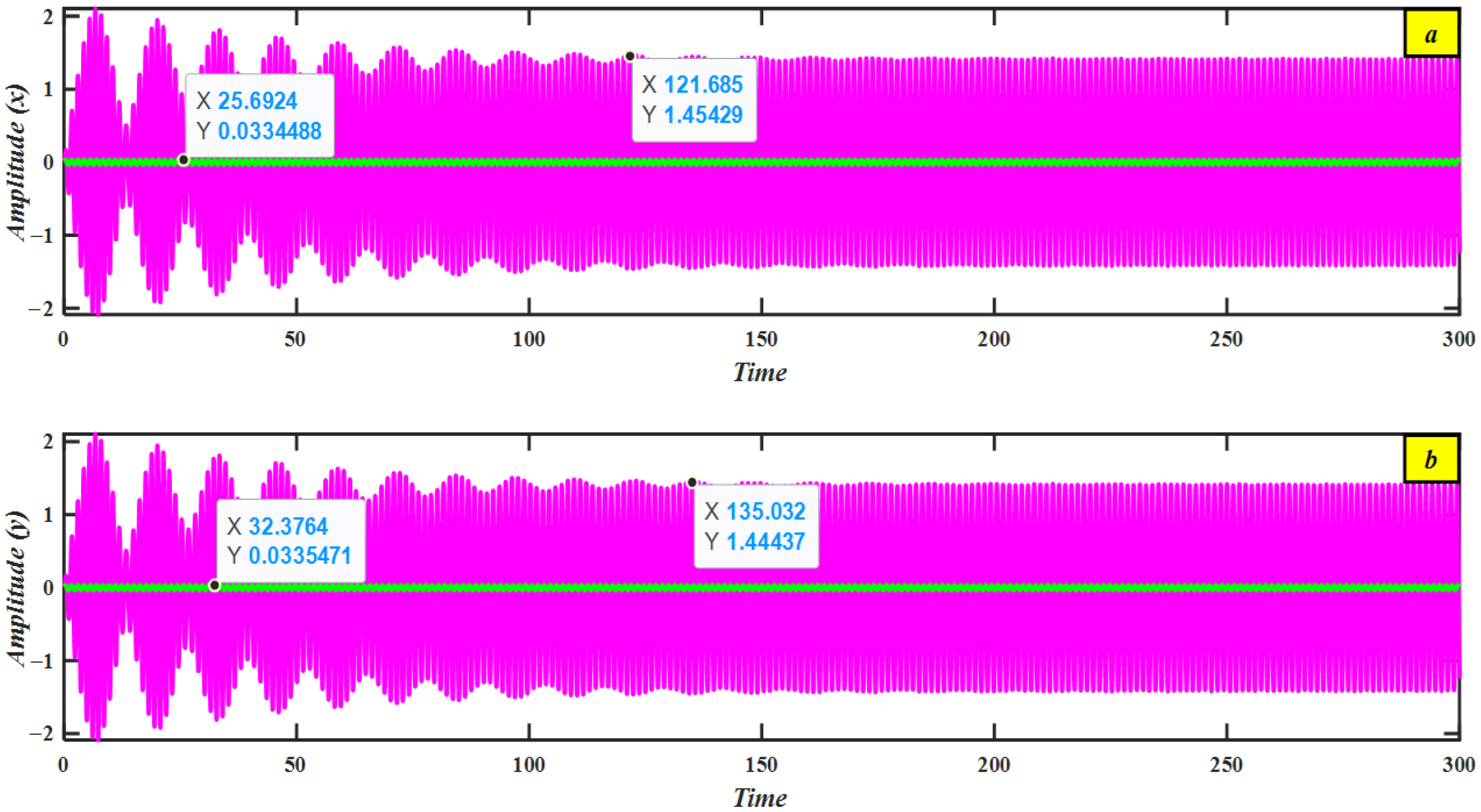
Figure 2 illustrates the steady-state amplitudes of the system before implementing PD controllers at the worst resonance case (approximately 1.4 and 1.4, respectively). After, the addition of PD controllers significantly reduces the system amplitudes to 0.03 and 0.03, respectively. This illustrates the effectiveness of the PD controllers, with Ea. = 46.6, Ea. = 46.6, and a reduction in vibrations by about 97.8% compared to their uncontrolled value.

4.2. Discussion of Frequency–Response Curve (FRC)

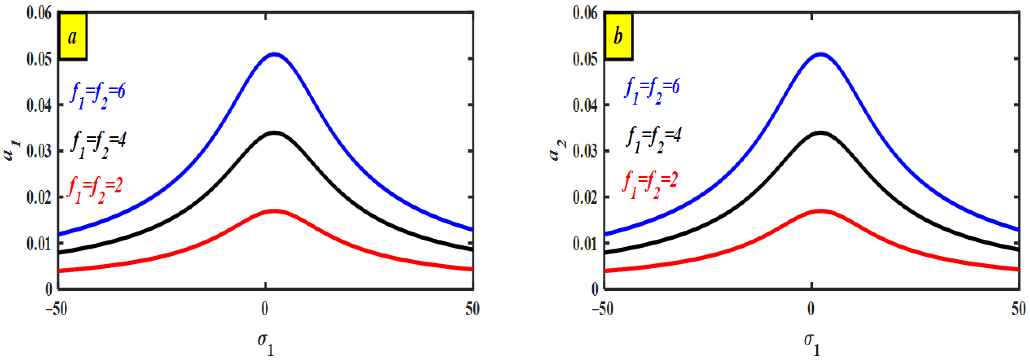
The rejoinder amplitude is determined by both the detuning parameters σ 1 , σ 2 and the excitation amplitude   f . FRE is explained numerically and graphically to determine solutions for the system and PD controller amplitudes, respectively. The graphical solution is obtained with respect to the detuning parameter σ 1 , σ 2 , giving a visual description of how the amplitudes of these systems vary as this parameter changes in the detuning parameter σ 1 , σ 2 , and one beak is used to indicate this. Figure 3, Figure 4, Figure 5, Figure 6, Figure 7, Figure 8, Figure 9 and Figure 10 demonstrate that the amplitudes of the frequency response curves can sometimes be asymmetrical, but adjusting various parameters can improve symmetry. Figure 3 presents the frequency response curves of the system with the PD controller. Subfigure (a) illustrates the first mode, and subfigure (b) illustrates the second mode, where solid lines indicate stable solutions. This figure enables a clear comparison of system responses across different frequencies and highlights the corresponding stability regions. The minimum amplitude of the primary system can also be observed in this graph σ 1 = 0 . Although the PD controller effectively suppresses vibrations under simultaneous resonance conditions, the amplitudes of the controlled system still increase as the harmonic excitation force f grows. The jump phenomenon occurs, resulting in the minimum achievable amplitude for the main system ensuing at σ 1 = σ 2 = 0 , as illustrated in Figure 4.
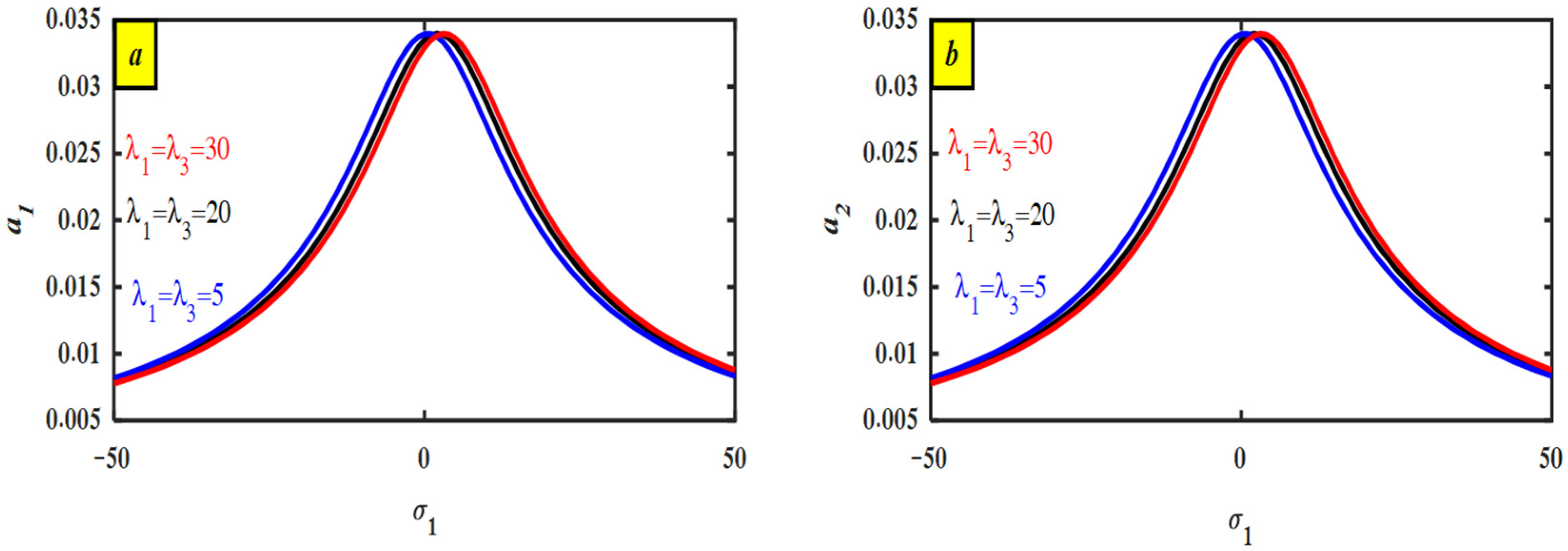
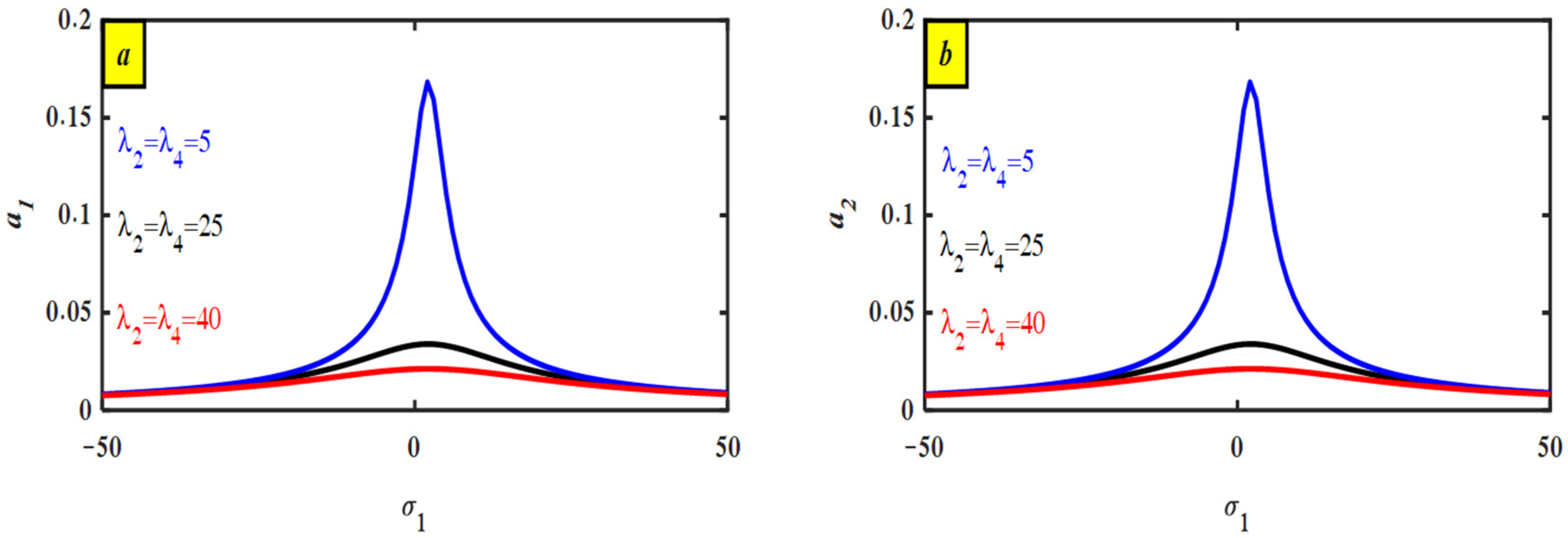
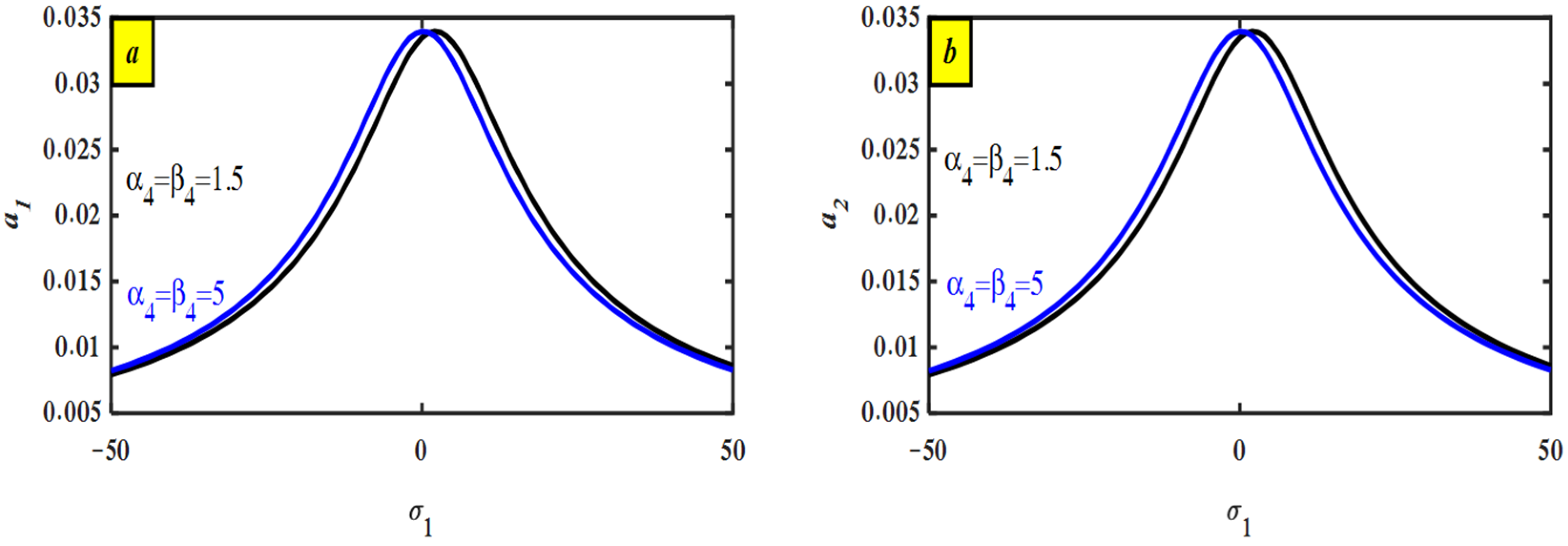
Figure 5, Figure 6, Figure 7, Figure 8, Figure 9 and Figure 10 illustrate the impact of a PD controller on system behavior under various conditions. Specifically, Figure 5 highlights the controller’s ability to suppress vibrations even in the presence of simultaneous resonance, with the smallest primary system amplitude observed at σ 1 = 0 . Interestingly, the figures also reveal a consistent pattern of amplitude shifting to the right as control parameters λ 1 , λ 3 are adjusted. This phenomenon is visible in Figure 5. Furthermore, the data indicates that increasing the control gain λ 2 , λ 4 leads to a further reduction in system amplitude. This trend is evident in Figure 6, where a monotonic decrease in amplitude is observed with increasing gain. Similarly, Figure 6 demonstrates the same effect of control gain λ 2 , λ 4 on system response. Overall, the results presented in Figure 5 and Figure 6 provide strong evidence for the efficiency of the PD controller in mitigating system vibrations across a range of frequencies and operating conditions. Figure 7 illustrates the stimulus of the damping μ 1 , μ 2 on the system’s vibration retort. The figure demonstrates that increasing the damping coefficient effectively reduces both the focal system’s amplitude and the corresponding controller amplitude, particularly around the frequency of simultaneous resonance. This suggests that the damping coefficient plays a significant role in the controller’s ability to suppress vibrations. Figure 8 illustrates the relationship between the nonlinear parameter α 4 = β 4 and system amplitudes. The data suggests that increasing the value of this nonlinear parameter corresponds to a shift to left in overall amplitudes. This implies that the nonlinear parameter plays a role in mitigating system response, with higher values leading to greater suppression. Figure 9 illustrates how the PD controller behaves at low natural frequencies of σ 2 = 0  (i.e.,) ( ω 1 = ω 2 ). The figure illustrates that, at low frequencies, both primary systems equipped with PD controllers exhibit increased peak amplitudes. Nevertheless, the controller maintains effective performance within this frequency range, indicating its suitability for systems characterized by low natural frequencies.
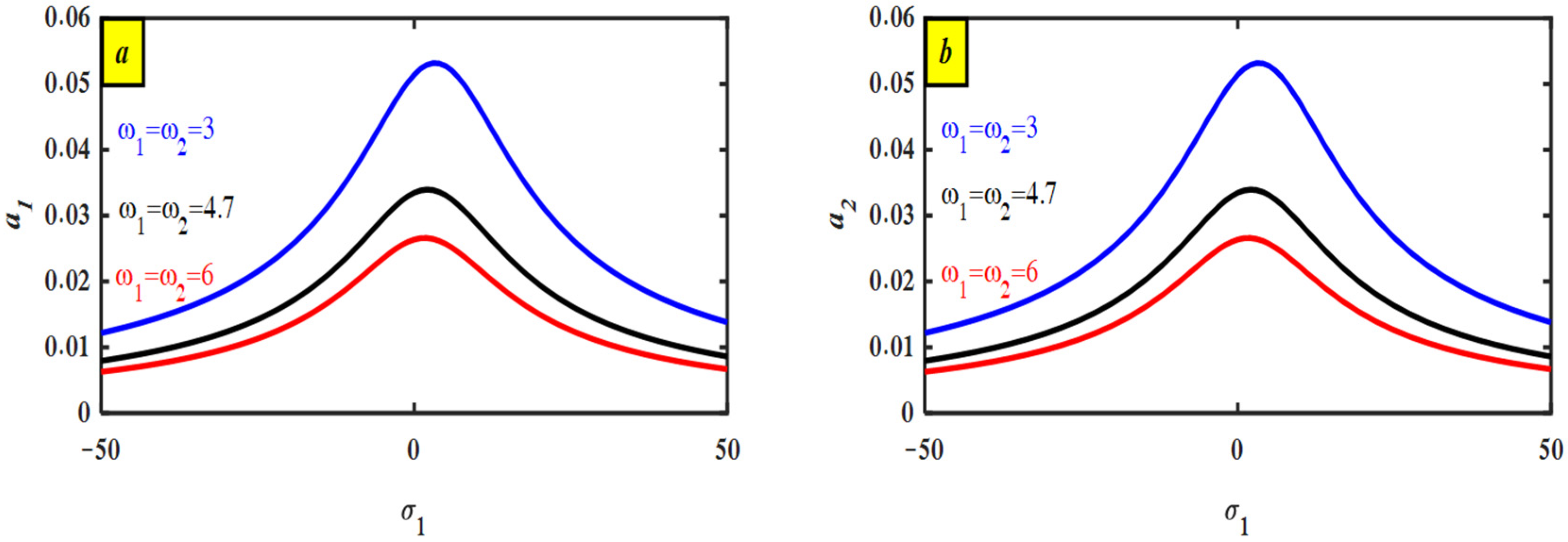
Figure 10 further explores the controller’s performance by examining three different values of the parameter indicated. The figure reveals that the focal structure’s amplitude reaches its tiniest rate at the time that this parameter is set to σ 1 = σ 2 . This finding highlights the PD controller’s enhanced efficiency in mitigating vibrations, particularly at resonance, where precise parameter tuning leads to optimal performance.

5. Bifurcation Diagrams

This subsection examines the system’s chaotic behavior, which is fundamental to understanding the complexity of nonlinear dynamical systems [37]. As system parameters vary, the system undergoes transitions that give rise to diverse dynamic responses, ranging from quasiperiodic motion to fully developed chaos. These transitions are visualized through the bifurcation diagram, which highlights how the system’s structure evolves in response to changes in a critical parameter.
The bifurcation analysis was conducted using the dimensionless form of Equations (3) and (4). To facilitate the analysis, these second-order differential equations were reformulated into an equivalent set of first-order equations. The resulting bifurcation diagrams, Poincaré maps, and phase portraits were generated using MATLAB and are presented in the subsequent results.
Figure 11 presents the bifurcation diagram, which identifies critical points where the system’s behavior shifts typically from quas-periodic motion to increasingly complex or chaotic dynamics ( Ω 4 ). These bifurcation points are essential for characterizing changes in the system’s stability. Notably, as the bifurcation parameter increases, the system often transitions from quas-periodic to chaotic behavior, a hallmark of many nonlinear systems.
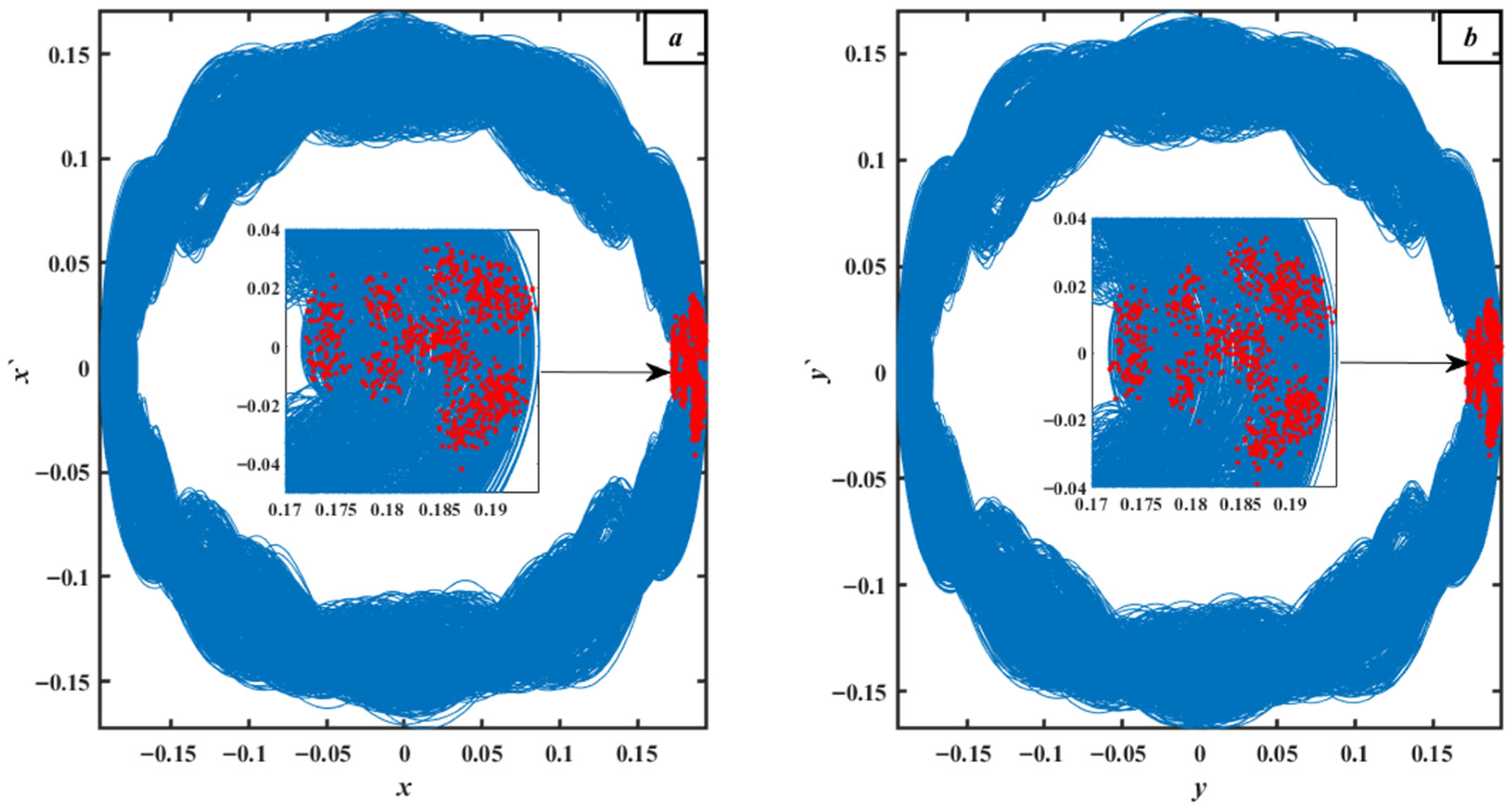
Figure 11a,b present the bifurcation graphs for λ 1 = λ 2 = λ 3 = λ 4 = 0.01 , revealing the following behavior: Within the ranges of Ω 4 < 1.9 , the bifurcation graph’s dispersed spots within this range, which show the breakdown of regular oscillations, make this clear. The presence of chaotic motion is further supported by the equivalent Poincaré sketch in Figure 12a,b, at Ω 4 = 0.75 , which shows randomly distributed red spots. The system shows a remarkable sensitivity to beginning conditions in this chaotic regime, where slight changes over time lead to noticeably different trajectories.
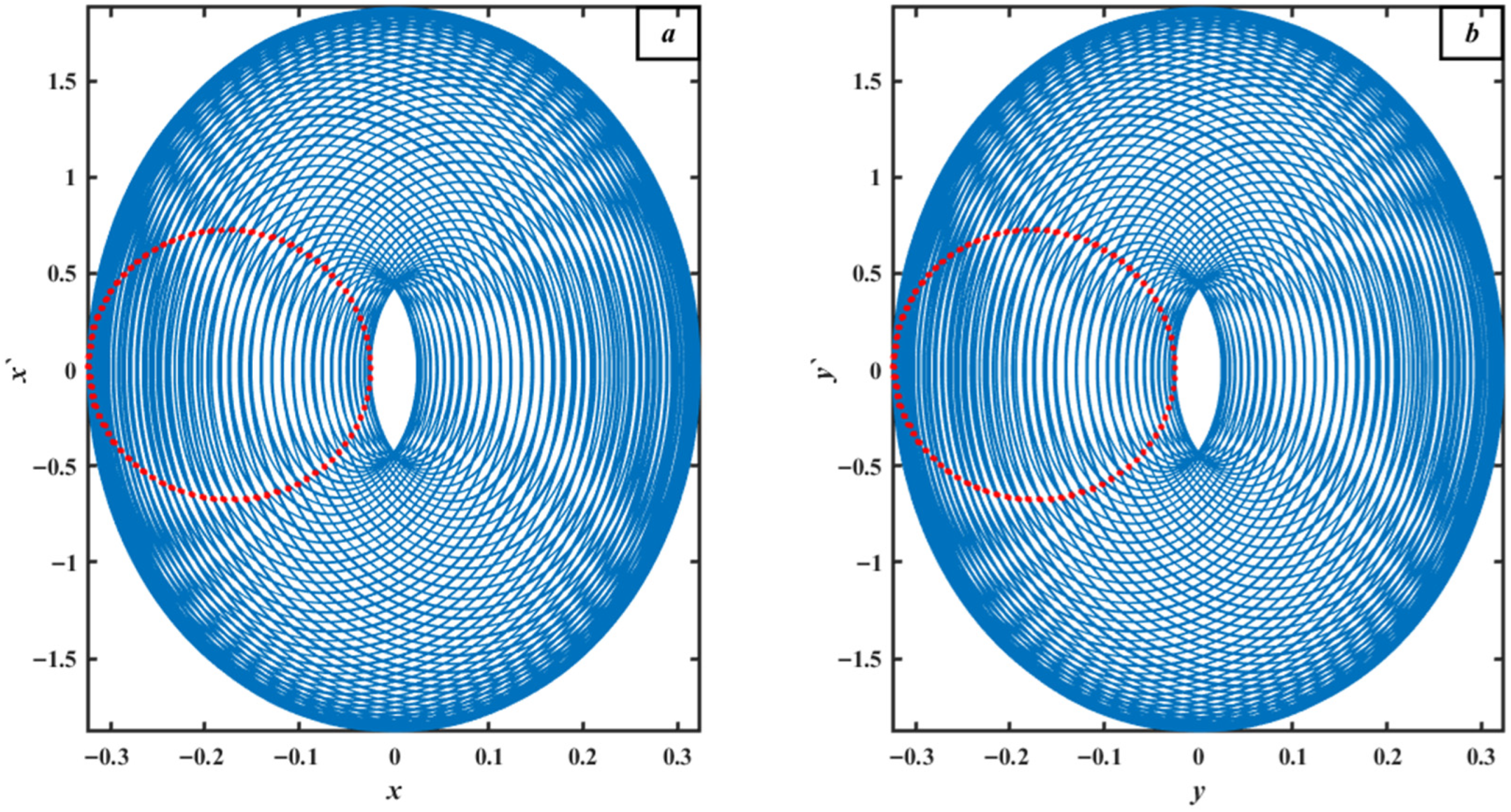
As Ω 4 increases to values between 1.9 and 10, the structure transitions from chaotic to quasiperiodic performance. This is evident in the bifurcation diagram within this range, indicating sustained regular oscillations. The resultant Poincaré map in Figure 13a,b at Ω 4 = 6.76 displays a closed loop, further confirming the quasiperiodic nature of the system’s dynamics. This phase is characterized by regular, non-chaotic oscillations with multiple incommensurate frequencies, resulting in quasiperiodic motion.

6. Comparison Graphs

6.1. Comparison Graphs via Time History Before and After the Controller

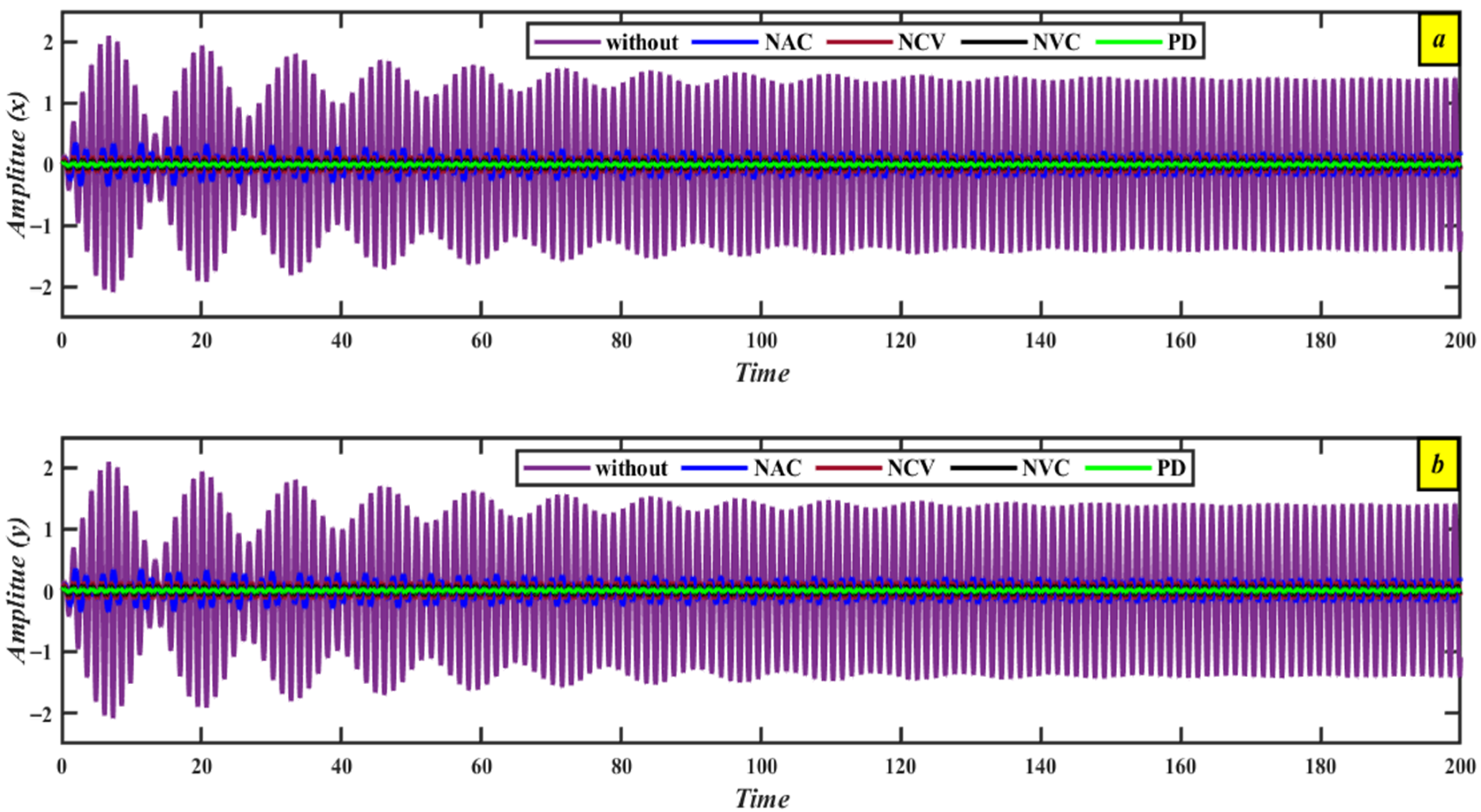
Figure 14 depicts the results of several control mechanisms implemented in the worst-case scenario. Several control kinds, including NAC, NCV, NVC, and PD, were tested to determine the effectiveness of each strategy. The results clearly show that the PD controller was the most successful at suppressing vibrations in the main system.

6.2. Assessment Graph via Perturbation Explanation and Numerical Reproduction

Figure 15 shows a high agreement between numerical and estimated results for systems managed by a PD controller. This tight connection supports the correctness and reliability of both approaches in recording system behavior under a variety of control settings. The consistency of these results illustrates the robustness of both numerical and approximate methods in studying the system’s dynamic response. We can present this comparison in Table 1.

6.3. Comparison with Previous Exertion

This paper introduces a PD controller based on the nonlinear vibration model of an axially moving wing aircraft, which models the wing as a stepped cantilever plate with aerodynamic forces, piezoelectric excitation, and in-plane excitation. The model is based on Reddy’s higher-order shear deformation theory and Hamilton’s principle, which are simplified by Galerkin’s technique. The examination of the system’s time history and important parameters shows that the PD controller is successful in lowering vibration amplitude by roughly 97% with a control effort of around 47. The strong agreement between numerical and approximate solutions confirms the accuracy of the method. While previous research has looked into nonlinear oscillations of composite piezoelectric plates under aerodynamic forces, such as [7], these studies did not specifically address the challenges posed by axially moving structures experiencing simultaneous resonance, nor did they use active PD control strategies for vibration suppression. Similarly, ref. [10] investigated PD control in a hybrid Rayleigh–Van der Pol–Duffing oscillator, concentrating on nonlinear dynamics but not axial motion or simultaneous resonance events. Furthermore, ref. [11] used PD control to improve the vibration performance and stability of wind turbine towers but did not account for the complex dynamics caused by simultaneous resonance in axially moving systems. In contrast, this study closes the gap by offering a PD-based control framework for nonlinear axially moving structures subjected to simultaneous resonance. The integration of axial motion, nonlinear dynamic modeling, and active PD control under simultaneous resonance conditions constitutes a novel contribution that, to our knowledge, has not been thoroughly explored in the existing literature.

7. Conclusions

This work explored the nonlinear dynamic behavior of an inner plate subjected to shuddering caused by contact-induced excitations, which resulted in complicated lateral vibrations perpendicular to its surface. To suppress these oscillations, a PD controller was proposed as an active control technique, with system dynamics represented using coupled nonlinear differential equations. Approximate analytical solutions produced through perturbation techniques were tested against numerical simulations to confirm the results’ credibility. The data reveal that the PD controller is highly effective in regulating the system response, with an amplitude decrease of nearly 97% compared to the uncontrolled condition. This demonstrates its excellent ability to dampen high-amplitude vibrations in nonlinear systems. Furthermore, the research demonstrated that steady-state amplitude increases with increasing excitation forces while decreasing inversely with both the damping factor and natural frequency. Frequency response analysis confirmed that the PD controller influences resonance characteristics by shifting response curves as control gains are varied; increasing the derivative gain moves the curves to the right, while increasing the proportional gain shifts them to the left, providing a useful mechanism for fine-tuning system performance. Stability tests using frequency response and numerical simulations confirmed that the closed-loop system is limited and avoids uncontrolled oscillations. Furthermore, the good agreement between analytical frequency response solutions and numerical findings obtained using the Runge–Kutta method validates the suggested strategy. Overall, the redesigned PD controller successfully reduced peak overshoot, shortened settling time, and improved structural stability, establishing it as a reliable technique for controlling nonlinear aeroelastic vibrations in axially moving wing systems.

Author Contributions

A.T.E.-S.: conceptualization, resources, methodology, writing—original draft preparation, visualization, reviewing, and editing. R.K.H.: investigation, methodology, formal analysis, reviewing and editing, and funding acquisition. Y.A.A.: investigation, methodology, data curation, validation, reviewing, and editing. M.A.E.-S.: formal analysis, validation, investigation, methodology, data curation, conceptualization, validation, and writing—review and editing. All authors have read and agreed to the published version of the manuscript.

Funding

This work was supported and funded by the Deanship of Scientific Research at Imam Mohammad Ibn Saud Islamic University (IMSIU) (grant number IMSIU-DDRSP2503).

Data Availability Statement

All data generated or analyzed during this study are included in this published article.

Acknowledgments

The authors extend their appreciation to the Deanship of Scientific Research at Imam Mohammad Ibn Saud Islamic University (IMSIU), KSA, for funding this research work through the project number “IMSIU-DDRSP2503”.

Conflicts of Interest

The authors declare no conflicts of interest.

List of Abbreviations and Symbols

The SymbolThe Meaning
MTSTMultiple time-scale technique
PDProportional derivative Feedback controller
SMSimultaneous resonance
FREsFrequency–response equations
IRInternal resonance
x , x ˙ , x ¨ Movement, speed, and acceleration of the primary mood of the system, consistently.
y , y ˙ , y ¨ Movement, speed, and acceleration of the second mood of system, respectively.
μ 1 , μ 2 System damping coefficients of the main system, respectively.
ω 1 , ω 2 The constancy of nature of the main system, respectively.
f 1 , f 2 , f 1 n , f 2 n   ( n = 1 , 2 , 3 ) Excitation forces
α 1 , α 2 , α 3 , α 4 , β 1 , β 2 , β 3 , β 4 Nonlinear coefficients of the main system
λ 1 , λ 2 , λ 3 , λ 4 The quantity of the PD control signal
Ω n   ( n = 1 , 2 , 3 , 4 ) Excitation frequency
ε Minor perturbation constraint

Appendix A

r 11 = 1 2 λ 1 1 2 μ 1 α 1 2 ω 1 a 1 a 2 sin ( ϕ 20 ) α 2 8 ω 1 a 2 2 sin ( 2 ϕ 20 ) , r 12 = f 1 2 ω 1 cos ( ϕ 10 ) , r 13 = 9 α 4 8 ω 1 a 2 2 sin ( ϕ 20 ) α 1 4 ω 1 a 1 2 ( ϕ 20 ) α 2 4 ω 1 a 2 a 1 sin ( 2 ϕ 20 ) , r 14 = 3 α 4 8 ω 1 a 2 3 cos ( ϕ 20 ) α 1 4 ω 1 a 1 2 a 2 cos ( ϕ 20 ) α 2 8 ω 1 a 2 2 a 1 cos ( 2 ϕ 20 ) , r 21 = σ 1 a 10 λ 1 2 ω 1 a 10 1 4 ω 1 a 10 α 2 a 20 2 9 α 3 8 ω 1 a 10 cos ϕ 20 α 1 2 ω 1 a 20 cos ϕ 20 α 2 8 ω 1 a 1 0 a 2 2 cos 2 ϕ 2 , r 22 = f 1 2 ω 1 a 10 sin ( ϕ 10 ) r 23 = 1 2 ω 1 α 2 a 20   9 α 4 8 ω 1 a 10 a 20 2 cos ϕ 20 α 1 4 ω 1 a 10 cos ϕ 20 α 2 4 ω 1 a 20 cos 2 ϕ 20 , r 24 = 3 α 3 8 ω 1 a 10 2 sin ϕ 20   + 3 α 4 8 ω 1 a 10 a 20 3 sin ϕ 20 + α 1 4 ω 1 a 10 a 20 cos ϕ 20 + α 2 8 ω 1 a 20 2 cos 2 ϕ 20 , r 31 = 9 β 4 8 ω 2 a 1 2 sin ϕ 20 + β 1 4 ω 2 a 2 2 sin ϕ 2 , r 32 = f 2 2 ω 2 cos ϕ 10 ϕ 20 , r 33 = 1 2 λ 4 1 2 μ 2 + β 1 2 ω 2 a 20 a 10 sin ϕ 20 , r 34 = f 2 2 ω 2 cos ϕ 1 ϕ 2 + 3 β 4 8 ω 2 a 10 3 cos ϕ 20 + β 1 4 ω 2 a 20 2 a 10 cos ϕ 20 r 41 = β 4 2 ω 2 a 10   + 9 β 4 8 ω 2 a 20 a 10 2 cos ϕ 20 + β 1 4 ω 2 a 20 cos ϕ 20 + r 21 , r 42 = f 2 2 ω 2 a 20 sin ϕ 10 ϕ 20 + r 22 , r 43 = σ 2 σ 1 a 20 + 9 β 3 8 ω 2 a 20 + β 4 4 ω 2 a 20 a 10 2 + 1 2 ω 2 a 20 λ 3 + β 1 2 ω 2 a 10 cos ϕ 20 + r 23 , r 44 = f 2 2 ω 2 a 20 sin ϕ 10 ϕ 20 3 β 4 8 ω 2 a 20 a 10 3 sin ϕ 20 + β 1 4 ω 2 a 20 a 10 cos ϕ 20 + r 24 Γ 1 = r 11 + r 22 + r 33 + r 44 , Γ 2 = r 22 r 11 + r 33 + r 44 + r 44 r 11 + r 33 + r 11 r 33 r 12 r 21 r 13 r 31 r 14 r 41 r 24 r 42 r 34 r 43 , Γ 3 = r 11 r 24 r 42 + r 34 r 43 r 22 ( r 33 + r 44 ) r 33 r 44 + r 22 r 13 r 31 + r 14 r 41 r 33 r 44 + r 34 r 43 + r 33 r 12 r 21 + r 14 r 41 + r 24 r 42 + r 44 r 12 r 21 + r 13 r 31 + r 12 r 23 r 31 + r 24 r 41 + r 14 r 21 r 42 + r 31 r 43 + r 34 r 13 r 41 + r 23 r 42 , Γ 4 = r 11 r 22 ( r 33 r 44 r 34 r 43 ) r 42 ( r 24 r 33 + r 23 r 34 ) r 22 r 41 ( r 14 r 33 + r 13 r 34 ) + r 31 ( r 13 r 44 + r 14 r 43 ) r 33 r 12 ( r 21 r 44 + r 24 r 41 ) + r 14 r 21 r 42 r 12 r 31 ( r 23 r 44 + r 24 r 43 ) r 34 ( r 21 r 43 r 23 r 41 ) + r 42 r 31 ( r 13 r 24 r 14 r 23 ) r 13 r 21 r 34

Appendix B

Derivation of Modal Equations
The modal equations are most often derived from the nonlinear vibration analysis of a plate or beam utilizing methods such as perturbation approaches. Here is an overview of how they are derived:
  • Begin with the governing equations of motion for a thin plate or beam, which are typically expressed by the Kirchhoff–Love plate theory or the Euler–Bernoulli beam equation:
    D   4 ω + ρ h 2 ω t 2 + n o n l i n e a r   t e r m s = F x   , y   , t
    where D is the flexural rigidity, ρ is density, h is thickness, and F x   , y   , t is external forcing.
  • Expand the displacement function ω x   , y   , t into modal shapes using the separation of variables:
    ω x   , y   , t = m , n Φ m , n x   , y q m , n t
    where Φ m , n x   , y are mode shapes and q m , n t are time-dependent modal coordinates.
  • Apply Galerkin’s method, multiplying by mode shapes and integrating over the plate domain, which reduces the PDE to ordinary differential equations (ODEs) for each mode.
  • Include nonlinear terms, which arise from geometric nonlinearity (von Kármán-type equations). These lead to terms like x 2 y , y 2 x , and cubic terms.
  • Introduce external forcing, such as periodic excitation f 1 cos Ω 1 t which drives the vibration.
  • Reference [7] provided a more comprehensive derivation of the equations and arrived at the equations referred to as (15) and (16). We have conducted the analysis and worked on these equations accordingly.

References

  1. Zhang, W.; Chen, L.L.; Guo, X.Y.; Sun, L. Nonlinear dynamical behaviors of deploying wings in subsonic air flow. J. Fluids Struct. 2017, 74, 340–355. [Google Scholar] [CrossRef]
  2. Sanders, B.; Crowe, R.; Garcia, E. Defense advanced research projects agency–smart materials and structures demonstration program overview. J. Intell. Mater. Syst. Struct. 2004, 15, 227–233. [Google Scholar] [CrossRef]
  3. Lu, S.F.; Xue, N.; Zhang, W.; Song, X.J.; Ma, W.S. Dynamic stability of axially moving graphene reinforced laminated composite plate under constant and varied velocities. Thin-Walled Struct. 2021, 167, 108176. [Google Scholar] [CrossRef]
  4. Torres, D.A.F.; Mendonça, P.T.R. Analysis of piezoelectric laminates by generalized finite element method and mixed layerwise-HSDT models. Smart Mater. Struct. 2010, 19, 035004. [Google Scholar] [CrossRef]
  5. Zhang, W.; Gao, Y.H.; Lu, S.F. Theoretical, numerical and experimental researches on time-varying dynamics of telescopic wing. J. Sound Vib. 2022, 522, 116724. [Google Scholar] [CrossRef]
  6. Liu, Y. Nonlinear dynamic analysis of an axially moving composite laminated cantilever beam. J. Vib. Eng. Technol. 2023, 11, 3307–3319. [Google Scholar] [CrossRef]
  7. Liu, Y.; Ma, W. Nonlinear Oscillations of a Composite Stepped Piezoelectric Cantilever Plate with Aerodynamic Force and External Excitation. Mathematics 2023, 11, 3034. [Google Scholar] [CrossRef]
  8. Bauomy, H.S.; El-Sayed, A.T. A new six-degrees of freedom model designed for a composite plate through PPF controllers. Appl. Math. Model. 2020, 88, 604–630. [Google Scholar] [CrossRef]
  9. Li, W.; Laima, S. Experimental Investigations on Nonlinear Flutter Behaviors of a Bridge Deck with Different Leading and Trailing Edges. Appl. Sci. 2020, 10, 7781. [Google Scholar] [CrossRef]
  10. Amer, Y.A.; Abd EL-Salam, M.N.; EL-Sayed, M.A. Behavior of a Hybrid Rayleigh-Van der Pol-Duffing Oscillator with a PD Controller. J. Appl. Res. Technol. 2022, 20, 58–67. [Google Scholar] [CrossRef]
  11. Hamed, Y.S.; Aly, A.A.; Saleh, B.; Alogla, A.F.; Aljuaid, A.M.; Alharthi, M.M. Vibration performance, stability and energy transfer of wind turbine tower via PD controller. Comput. Mater. Contin. 2020, 64, 871–886. [Google Scholar] [CrossRef]
  12. Ren, Y.; Ma, W. Dynamic Analysis and PD Control in a 12-Pole Active Magnetic Bearing System. Mathematics 2024, 12, 2331. [Google Scholar] [CrossRef]
  13. Hamed, Y.S.; Alotaibi, H.; El-Zahar, E.R. Nonlinear vibrations analysis and dynamic responses of a vertical conveyor system controlled by a proportional derivative controller. IEEE Access 2020, 8, 119082–119093. [Google Scholar] [CrossRef]
  14. Bahnasy, T.A.; Amer, T.S.; Abohamer, M.K.; Abosheiaha, H.F.; Elameer, A.S.; Almahalawy, A. Stability and bifurcation analysis of a 2DOF dynamical system with piezoelectric device and feedback control. Sci. Rep. 2024, 14, 26477. [Google Scholar] [CrossRef]
  15. Jamshidi, R.; Collette, C. Optimal negative derivative feedback controller design for collocated systems based on H2 and H method. Mech. Syst. Signal Process. 2022, 181, 109497. [Google Scholar] [CrossRef]
  16. Amer, Y.A.; Abd EL-Salam, M.N. Negative Derivative Feedback Controller for Repressing Vibrations of the Hybrid Rayleigh-Van der Pol-Duffing Oscillator. Nonlinear Phenom. Complex Syst. 2022, 25, 217–228. [Google Scholar] [CrossRef]
  17. Alluhydan, K.; Amer, Y.A.; El-Sayed, A.T.; EL-Sayed, M.A. Controlling the Generator in a Series of Hybrid Electric Vehicles Using a Positive Position Feedback Controller. Appl. Sci. 2024, 14, 7215. [Google Scholar] [CrossRef]
  18. Bahnasy, T.A.; Amer, T.S.; Almahalawy, A.; Abohamer, M.K.; Abosheiaha, H.F.; Elameer, A.S. A chaotic behavior and stability analysis on quasi-zero stiffness vibration isolators with multi-control methodologies. J. Low Freq. Noise Vib. Act. Control. 2025, 44, 1094–1116. [Google Scholar] [CrossRef]
  19. Hamed, Y.S.; Alharthi, M.R.; AlKhathami, H.K. Nonlinear vibration behavior and resonance of a Cartesian manipulator system carrying an intermediate end effector. Nonlinear Dyn. 2018, 91, 1429–1442. [Google Scholar] [CrossRef]
  20. Ngouabo, U.G.; Tuwa, P.R.; Noubissie, S.; Woafo, P. Nonlinear analysis of electrostatic micro-electro-mechanical systems resonators subject to delayed proportional–derivative controller. J. Vib. Control 2020, 27, 220–233. [Google Scholar] [CrossRef]
  21. Seth, S.; Kudra, G.; Wasilewski, G.; Awrejcewicz, J. Study the bifurcations of a 2DoF mechanical impacting system. Nonlinear Dyn. 2024, 112, 1713–1728. [Google Scholar] [CrossRef]
  22. Alluhydan, K.; Amer, Y.A.; El-Sayed, A.T.; EL-Sayed, M.A. The Impact of the Nonlinear Integral Positive Position Feedback (NIPPF) Controller on the Forced and Self-Excited Nonlinear Beam Flutter Phenomenon. Symmetry 2024, 16, 1143. [Google Scholar] [CrossRef]
  23. Nussbaumer, E.J.; Hijazi, S.; Bergmann, D.P.; Hanno, S.; Strohmayer, A. Development of a Modular Test Rig for In-Flight Validation of a Multi-Hole Probe Onboard the e-Genius-Mod. Aerospace 2025, 12, 345. [Google Scholar] [CrossRef]
  24. Taufik, N.Z.B.; Zaidaan, S.; Mahmoud, E.; Abdallah, A.M.; Manaa, Z.; Abro, G.E.M.; Taib, M.N. Design and Analysis of the Effect of Trimmable Vertical Stabilizers for Enhanced Aircraft Maneuverability and Directional Stability. In Proceedings of the 2024 IEEE 12th Conference on Systems, Process & Control (ICSPC), Malacca, Malaysia, 7 December 2024; pp. 251–256. [Google Scholar]
  25. Zhu, Q.; Yue, J.Z.; Liu, W.Q.; Wang, X.D.; Chen, J.; Hu, G.D. Active vibration control for piezoelectricity cantilever beam: An adaptive feedforward control method. Smart Mater. Struct. 2017, 26, 047003. [Google Scholar] [CrossRef]
  26. Kandil, A.; Hamed, Y.S.; Awrejcewicz, J.; Saeed, N.A. Multiple Time-Scales Analysis to Predict the Quasiperiodic Oscillatory Response of a Thin-Walled Beam Subjected to 1: 1: 1 Simultaneous Resonance. Shock. Vib. 2023, 6616922. [Google Scholar] [CrossRef]
  27. Saeed, N.A.; Awrejcewicz, J.; Elashmawey, R.A.; El-Ganaini, W.A.; Hou, L.; Sharaf, M. On 1/2-DOF active dampers to suppress multistability vibration of a 2-DOF rotor model subjected to simultaneous multiparametric and external harmonic excitations. Nonlinear Dyn. 2024, 112, 12061–12094. [Google Scholar] [CrossRef]
  28. Fyrillas, M.M.; Szeri, A.J. Control of ultra-and subharmonic resonances. J. Nonlinear Sci. 1998, 8, 131–159. [Google Scholar] [CrossRef]
  29. Azimov, B.M.; Ikhsanova, S.Z. Mathematical modelling and numerical methods for studying the dynamic stability of the movement of cotton harvesters on slopes. In E3S Web of Conferences; EDP Sciences: Les Ulis, France, 2023; Volume 386, p. 03005. [Google Scholar]
  30. Kandil, A.; Hamed, Y.S.; Alsharif, A.M. Rotor active magnetic bearings system control via a tuned nonlinear saturation oscillator. IEEE Access 2021, 9, 133694–133709. [Google Scholar] [CrossRef]
  31. Bauomy, H. Safety action over oscillations of a beam excited by moving load via a new active vibration controller. Math. Biosci. Eng. 2023, 20, 5135–5158. [Google Scholar] [CrossRef] [PubMed]
  32. Saeed, N.A.; Awrejcewicz, J.; Hafez, S.T.; Hou, L.; Aboudaif, M.K. Stability, bifurcation, and vibration control of a discontinuous nonlinear rotor model under rub-impact effect. Nonlinear Dyn. 2023, 111, 20661–20697. [Google Scholar] [CrossRef]
  33. Elashmawey, R.A.; Saeed, N.A.; Elganini, W.A.; Sharaf, M. An asymmetric rotor model under external, parametric, and mixed excitations: Nonlinear bifurcation, active control, and rub-impact effect. J. Low Freq. Noise Vib. Act. Control 2024, 43, 1793–1826. [Google Scholar] [CrossRef]
  34. Kevorkian, J.; Cole, J.D. The method of multiple scales for ordinary differential equations. In Multiple Scale and Singular Perturbation Methods; Springer: New York, NY, USA, 1996; pp. 267–409. [Google Scholar] [CrossRef]
  35. Nayfeh, A.H. Perturbation Methods; Wiley: New York, NY, USA, 2000. [Google Scholar] [CrossRef]
  36. Dukkipati, R.V. Solving Vibration Analysis Problems Using Matlab; New Age International Pvt Ltd. Publishers: New Delhi, India, 2007. [Google Scholar]
  37. Crawford, J.D. Introduction to bifurcation theory. Rev. Mod. Phys. 1991, 63, 991. [Google Scholar] [CrossRef]
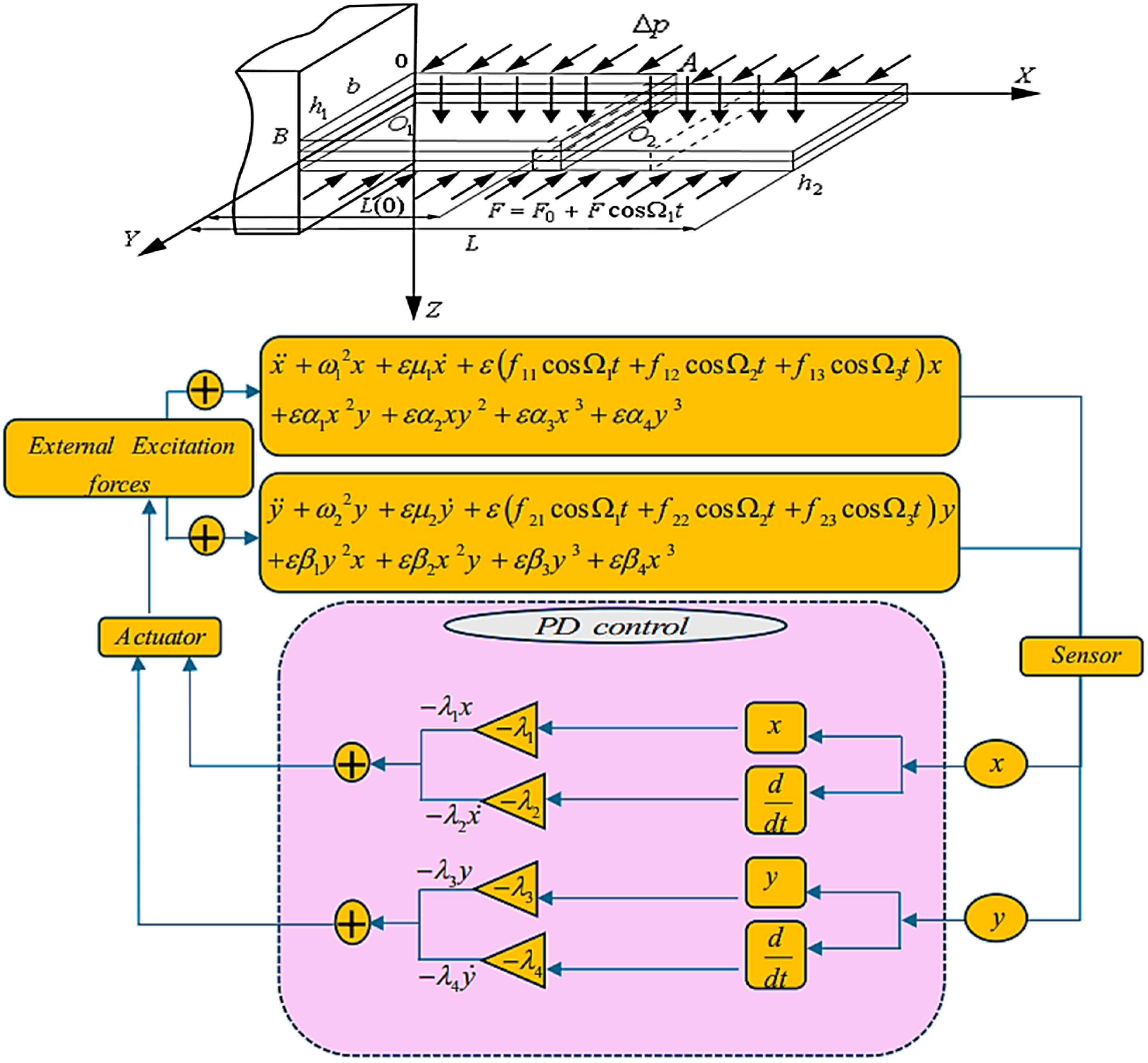
Figure 1. Block chart of an inner plate with a PD controller top part from [7].
Machines 13 00828 g001
Figure 2. The amplitude of the uncontrolled focal system (a) The amplitude of the first mode system ( x ) (b) The amplitude of the second mode system ( y ).
Machines 13 00828 g002
Figure 3. FRC for the controlled system with a PD controller (a) a 1 via σ 1 (b) a 2 via σ 1 .
Machines 13 00828 g003
Figure 4. The act of external force f 1 = f 2 on a system with a PD controller (a) a 1 via σ 1 (b) a 2 via σ 1 .
Machines 13 00828 g004
Figure 5. The act of changing the values of a relation λ 1 = λ 3 on a system with a PD controller (a) a 1 via σ 1 (b) a 2 via σ 1 .
Machines 13 00828 g005
Figure 6. The act of changing the values of a relation λ 2 = λ 4 on a system with a PD controller (a) a 1 via σ 1 (b) a 2 via σ 1 .
Machines 13 00828 g006
Figure 7. The act of changing the values of a relation μ 1 = μ 2 on a system with a PD controller (a) a 1 via σ 1 (b) a 2 via σ 1 .
Machines 13 00828 g007
Figure 8. The act of changing the values of the nonlinear parameter relation α 4 = β 4 on a system with a PD controller (a) a 1 via σ 1 (b) a 2 via σ 1 .
Machines 13 00828 g008
Figure 9. Act of σ 2 on a system with a PD controller (a) a 1 via σ 1 (b) a 2 via σ 1 .
Machines 13 00828 g009
Figure 10. The act of changing ω 1 = ω 2 on a system with a PD controller (a) a 1 via σ 1 (b) a 2 via σ 1 .
Machines 13 00828 g010
Figure 11. Bifurcation diagram of (a) x and (b) y vs. Ω 4 with PD control at λ 1 = λ 2 = λ 3 = λ 4 = 0.01 .
Machines 13 00828 g011
Figure 12. Phase portraits (blue) and Poincaré maps (red) of the chaotic behavior at Ω 4 = 0.75 : (a) x ; (b) y .
Machines 13 00828 g012
Figure 13. Phase portraits (blue) and Poincaré maps (red) of the quasiperiodic state at Ω 4 = 6.76 : (a) x , (b) y .
Machines 13 00828 g013
Figure 14. Outcome among the changed kinds of controllers (a) The amplitude of the first mode system ( x ) (b) The amplitude of the second mode system ( y ).
Machines 13 00828 g014
Figure 15. Contrast between the numerical solution (ـــــــــ) and the approximate solution (………) (a) The amplitude of the first mode system ( x ) (b) The amplitude of the second mode system ( y ).
Machines 13 00828 g015
Table 1. Values of the numerical solution and the approximate solution.
Value First Mode of the System Second Mode of the System
Numerical Solution Approximate Solution Numerical Solution Approximate Solution
A0.03349490.03349490.03349460.0334946
B0.03349450.03349450.03349450.0334945
C−0.0334897−0.0334897−0.0332704−0.0332704
D−0.0334947−0.0334947−0.0334946−0.0334946
Disclaimer/Publisher’s Note: The statements, opinions and data contained in all publications are solely those of the individual author(s) and contributor(s) and not of MDPI and/or the editor(s). MDPI and/or the editor(s) disclaim responsibility for any injury to people or property resulting from any ideas, methods, instructions or products referred to in the content.