Abstract
The rapid development of spacecraft on-orbit services has increased the requirements for docking technology, especially for large-scale payloads that exceed the launch envelope. Docking technology based on astronaut extravehicular activities is one of the most promising directions for on-orbit services. In view of this, this paper designs and characterizes a handheld double-point docking mechanism for assembling large-scale payloads that is suitable for extravehicular activity (EVA) in dual-astronaut collaborative operations. It achieves the functional decoupling of docking, locking, unlocking, and separation throughout the whole process. The mechanism also has excellent design for human factors engineering, allowing astronauts to change hands, operate with one hand, and apply limited force. The mechanism adopts a dual-point probe–drogue configuration, while the misalignment tolerance design guarantees the docking accuracy and the operating range, and forms a rigid structural connection through a force amplification mechanism. Theoretical analysis and numerical simulations are implemented to estimate the dynamics, statics, and kinematics of the docking process. Corresponding experiments of the prototype are also conducted, including high–low temperature dynamics, docking tests, and kinematic tolerance experiments. The experiments validate the finite element analysis and verify the actual performance of the mechanism. The designed handheld dual-point docking mechanism was successfully applied for the first time by the Shenzhou 15 crew on China’s Space Station in March 2023. This paves a new road for spacecraft on-orbit service of large-scale payloads by EVAs, providing guidance as well as a technical foundation for the on-orbit construction of large spacecraft in the future.
1. Introduction
The concept of on-orbit service of spacecraft has been successfully implemented in a large number of manned missions since first proposed in the 1960s [1]. During the Skylab mission in 1973, the practicality of on-orbit service was demonstrated for the first time by accomplishing a series of astronaut operations, including repairing solar arrays and microwave antennas, and the placement of some key components to improve the spacecraft performance [2]. Subsequently, with the development of the space shuttle in 1981, astronauts performed a number of world-astonishing on-orbit maintenance operations on the Solar Maximum Satellite (SMM) and even the Hubble Space Telescope (HST) during Columbia and Challenger space shuttle missions [3]. In 1997, the first autonomous servicing spacecraft, ETS-VII, equipped with a space robot, and the Orbital Express project in 2007 were milestone achievements that demonstrated the viability of on-orbit service technologies, including autonomous rendezvous and capture, refueling, and replacement of the Orbital Replacement Unit (ORU) [4]. With the successful construction of multiple projects such as the International Space Station (ISS), Phoenix, and the Intelligent Building Blocks for On-Orbit Satellite Servicing (iBOSS) [5], the architecture and understanding of on-orbit service have been continuously updated and deepened.
At present, on-orbit service is generally defined as the completion of space assembly, maintenance, and service tasks involving the extension of the life and capabilities of satellites, platforms, space station modules, and space vehicles, through the collaboration of humans and robots (or robot-like satellites), or both, in space [6]. There are many different ways to classify on-orbit service. According to the target objects, it can be divided into high orbit and low orbit, as well as cooperative and non-cooperative targets. With respect to the mission type, it generally includes on-orbit assembly, on-orbit maintenance, and on-orbit supply support [7,8,9,10]. The key technologies include system mission design, payload design, docking technology [11], orbit and control [12,13,14], etc.
With the development of payload characteristics such as larger volume, greater complexity, more power consumption, and better precision, payloads tend to exceed the traditional envelope constraints at launch, even in a folded state. Therefore, docking technology has gradually become one of the main challenges [15]. According to the classification of scale and tasks, it can be roughly divided into two categories, namely, spacecraft docking and payload docking. Spacecraft docking technology mainly uses the cone–rod docking mechanism and the Androgynous Peripheral Assembly System (APAS) [16]. The cone–rod scheme was developed by Russia and successfully applied on orbit for the first time in 1967 [17]. As one of the most popular docking systems, the APAS docking scheme consists of a ring equipped with a guide rail and a capture latch and a docking ring with a capture latch and a seal. Its diameter exceeds 1 m, and the mass exceeds 600 kg, with a maximum angular deviation of 5° [18]. In order to reduce the impact force while docking, the National Aeronautics and Space Administration (NASA) has developed a low-impact docking system [19], which uses a closed-loop active force feedback control to achieve soft impact capture [11,12,13]. In the Orbital Express Mission of the Defense Advanced Research Projects Agency (DARPA), the docking scheme consists of a passive side and an active side. The active side contains three gripping fingers and a shared actuator, while the passive side consists of three wedges. The gripping fingers engage with the shelf structure and the motor provides a preload force to establish a rigid connection with a maximum angular deviation of 5° [20]. The European Space Agency has developed a docking scheme called the International Berthing and Docking Mechanism. It consists of an upper ring and a middle ring, with six load-bearing elements arranged at 45° between the two rings [21]. The spacecraft docking schemes are all carried out unmanned. They are usually integrated into a whole structure of a large size and heavy weight, with docking vibration damping and high-rigidity connections that can adapt to the docking of spacecraft.
Payload docking technology can be roughly divided into two categories. The first usually utilizes robotic arms that are driven by motors on remote control, or even entirely mechanical [22,23]. This technology is strongly dependent on the performance of the robotic arms, and not all spacecraft is equipped with robotic arms [24,25]. Typical payload docking schemes include the Exposed Facility Docking Mechanism (EFBM) and the Adapter for Extra-vehicular Payload (AEP). The EFBM is deployed in Japan’s Extravehicular Exposure Experiment Platform [26]. It is used to mount and fix exposed payloads [27] with a maximum size of over ∅1.5 m, a mass of more than 160 kg, a load-to-self-weight ratio of 24, and an angular deviation of ±1.5°. The AEP is used to fix small-to-medium-sized payloads [28], such as China’s Space Station payload adapter [29], with a maximum diameter of more than ∅450 mm, a mass of 21 kg, a maximum angular deviation of ±2°, and a load-to-self-weight ratio of 7.6. Japan’s ETS-VII uses a claw-type capture mechanism [30], with a maximum dimension of over ∅1.5 m, a mass of 80 kg, a maximum angular deviation of ±2°, and a load-to-self-weight ratio of 36.
The other payload docking scheme is suitable for manual operation, and astronauts usually made use of hand-operated equipment such as device handles to capture and dock with the spacecraft, as well as electric tools to achieve rigid connection between the payload and the cabin itself [31]. Statistics of the past EVAs indicates that more than 40% of EVA actions are related to on-orbit maintenance, namely plugging and unplugging connectors, tightening and loosening bolts, and equipment assembly and replacement [32]. The typical docking mechanisms are the American FRAM and Russian URM-D [33,34]. The FRAM mechanism is planar and attached to the payload. The passive and active sides are locked through four plugs by an EVA handle, and the force is transformed by the lead screw pair. The URM-D adapter is orientated by a square plug-hole and similarly also locked by operation force on handle. Neither of these mechanisms is able to prevent payload escape during the capture process. They also cannot adapt to multi-person collaborative operation when faced with large-scale payloads such as a planar antenna of several square meters in area and several hundred kilograms in weight [35]. In addition, the limited manual operating force, the range of motion, and the demand for miniaturization and lightweight also restrict their application scenarios. This is because astronauts need to restrain their own position or hold somewhere tightly to provide reaction support, and the mission resources are usually rather limited. Therefore, the state-of-the-art docking mechanism technologies are difficult to adapt to the on-orbit assembly of large-scale payloads based on EVAs.
To satisfy the special requirements of EVAs and large-scale payload on-orbit assembly, this paper proposes a handheld dual-point docking mechanism suitable for EVAs. Its functions include capturing, anti-escape docking, soft and structural connection, locking and unlocking, and unlocked-maintaining-state entry and relief. The mechanism is described in detail regarding system design, concept of operation, and misalignment tolerance design. The multibody dynamic, static, and kinematic simulations are performed to analyze the operating force, stress on parts, and initial docking boundary conditions for verification. An overview of the experimental results is presented and compared with theoretical and simulation analysis in terms of operating force and misalignment tolerance. Due to its characteristics and performance, such kind of handheld dual-point docking mechanism is promising in applications of on-orbit service of EVAs, especially for large-scale payloads.
2. Mechanism Design
2.1. Docking Mechanism Design
Considering the large dimension of payload, such as the large-scale planar antenna with the side length of several meters and the mass of several hundred kilograms, the traditional single-point docking configuration performs unsatisfactorily under on-orbit loads in terms of structural stiffness. It also requires more volume and weight to withstand harsh load conditions together with structural frames. To strike a balance between reliable structural connection and limited resources, the proposed docking system consists of a dual-point docking mechanism. Though the dual-point docking architecture introduces issues such as a dual-point over-constrained location and dual-astronaut collaboration, it remarkably improves the connected structural stiffness and simplifies either mechanism.
The docking mechanism adopts the traditional probe–drogue architecture with two passive probes on the spacecraft chased by both active drogues on the payload. As for the dual-point system configuration, either side is called a set of docking mechanism composed of probe–drogue, as depicted in Figure 1.
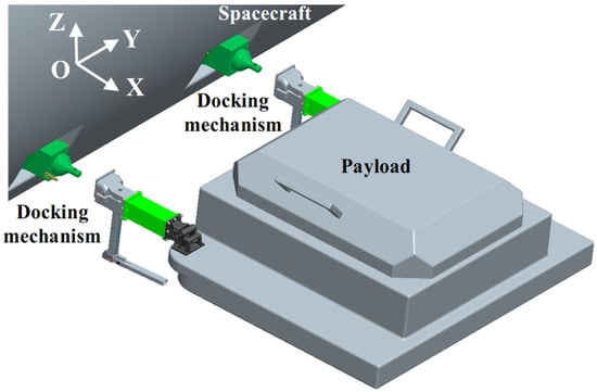
Figure 1.
3D model sketch of the docking mechanism application scenario.
The passive probe is designed to be located outside the spacecraft as the passive port of docking interface with no power supply. The inclination of the probe-mounting flange can be adjusted to fit different positions. The static probe architecture reduces moving parts to minimum with a docking cone and a docking plane on it. Weight reduction measurements are also taken. To ensure the docking accuracy and tolerance, two special docking shafts for the fine and rough fit of sliding pair are set as Dfine and drough with a docking cone in between. There is a through-hole inside the thinner docking shaft to impose preload by the latch in the active drogue part. The through-hole has an inclined sidewall with the self-locking angle γ. The pointer is mounted on the side face of the probe to give the docking-insertion signal. The structure of passive probe is presented in Figure 2.

Figure 2.
Schematic of the passive probe with (a) axonometry drawing and (b) part of cross-section.
The active drogue part is composed of housing base and grab-part, as shown in Figure 3. The housing base is rigidly connected with the payload as the active port of docking interface. The conical drogue is applied to tolerate lateral and angular misalignment during docking. There are spring-damper components in it to restrict the latch components and provide docking damping. The grab-part consists of latch components, disk spring components, a slider-crank mechanism, unlocked-state-maintenance components, and an operating handle.
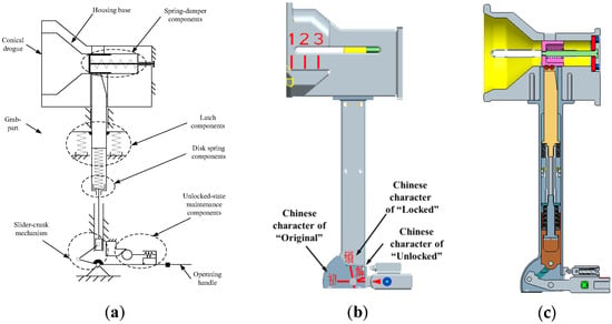
Figure 3.
The active drogue part structure: (a) schematic diagram; (b) external view of 3D model where red Arabic numerals of “one”, “two”, and “three” are etched on the side surface of drogue to indicate docking-insertion depth; (c) section view of 3D model.
When the spring-damper components are compressed by the thinner docking shaft in the passive probe part, the latch automatically inserts into the through-hole of the thinner docking shaft by the latch-spring, instead of manual operation. This achieves preliminary connection and prevents the escape of the payload during astronauts’ hand change. By adjusting the compressed height, the disk spring components provide compression force on the latch components. The slider-crank mechanism amplifies manual operation force and achieves self-locking function by the dead point position. Further investigation on the optimization of more advanced and efficient mechanism will be addressed in our future work, which would assist to obtain greater displacement conversion and larger compression force amplification in the limited space restricted by EVA human factors engineering requirements. The operating handle can be detachable to reduce the envelope of the active drogue part at launch, and it is drawn as a fixed connection for simplification in Figure 3.
From the perspective of force transmission path, as the astronaut rotates the operating handle clockwise, the slider-crank mechanism is driven to compress the disk spring components. Subsequently through the exchanged force at the inclined sidewall of latch, axial preload is imposed on the docking plane to establish a rigid connection. Here, we define “locking depth” as the distance between the top surface of latch and the upper surface of drogue, labeled by h1. We also regard “locking length” as the fit length on the inclined sidewall of the latch and the thinner docking shaft, which is represented by h2 to assess the imposed preload. In consequence, the locking function is decoupled of the docking function.
In terms of payload replacement for further maintenance, astronauts need to unlock and undock the mechanism. Because of the anti-escape function of the latch components, which is an advantage during docking, special unlocked-state-maintenance components are designed to resist the latch-spring force. They keep the unlocked state by the roller climbing the wedge. This enables astronauts to change one hand from the operating handle to the shell of the grab-part, minimizing the manual disturbance torque and enhancing operation convenience during undocking. Therefore, the separating function is decoupled of unlocking function.
It is also necessary to design indicators of human factors engineering to guide manual operation. There are Arabic numerals of “one”, “two”, and “three” etched on the side surface of drogue, corresponding to the pointer in the probe to indicate docking-insertion depth. Characters of “Original”, “Locked”, and “Unlocked” are marked on the side surface of grab-part to match with the arrow on the operating handle, representing three stages of approaching, locking, and unlocked-state maintenance.
The main function of the docking mechanism aims to provide structural connection between the payload and spacecraft. The system design is driven by many constraints and requirements grouped into four standard categories, i.e., functional, performance, design, and operational [36], which are listed below.
R1 (functional): It allows the capture with anti-escape function as the payload enters the docking envelope. This enables the human factors engineering operation to change hands and operate with one hand.
R2 (functional): The docking mechanism shall establish and release a rigid connection with axial preload over 1000 N. This is derived from the on-orbit spacecraft operating conditions caused by movement, docking impact, and so on.
R3 (performance): The docking system ought to tolerate the lateral and angular misalignment of pitch, yaw, and roll according to the human factors engineering of dual-astronaut collaboration ability. This enables the docking mechanism suitable for misalignment due to spacecraft inner air pressure, temperature variations, on-orbit loads and on-ground assembly errors, etc.
R4 (performance): The pitch and roll angle of perpendicular pointing accuracy of the assembled payload both shall be no more than 0.1°. This ensures the performance of large-scale payload.
R5 (performance): Operating force during the whole procedures should fall within the range of astronaut operating ability, namely, below 100 N. This is based on the human factors engineering.
R6 (design): The envelop and mass of the mechanism depend on the flight environment and constraints, since the driving source comes from astronauts instead of motors.
R7 (operational): Visible indicators and tactile perception are presented at each step to satisfy human factors engineering.
2.2. Concept of Operation
The docking sequence is suitable for manual operation of EVAs. Docking operations start as the payload is shifted close enough (i.e., less than 0.5 m) to target spacecraft with the assistance of robotic arms. The active drogues of the docking mechanism are subsequently adjusted to face the passive probes under control of two astronauts. The docking procedure is illustrated as follows and shown in Figure 4 where the fixed symbol means it is fixed with payload together.
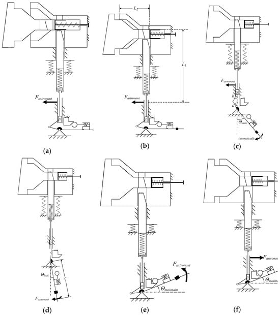
Figure 4.
Schematic of the handheld docking mechanism concept of operation: (a–f), where variable a stands for the length of the driving connecting rod in the slider-crank mechanism, b represents the length of the driven connecting rod in the slider-crank mechanism, and c means the arm of the manual operating torque.
Approaching—The grab-part of the active drogue in the docking mechanism is held by astronauts to move the payload towards the target, as shown in Figure 4a. The thinner shaft of the probe starts entering the envelop of the drogue conic hole. The pointer on the probe is aligned with the Arabic numeral of “one” on the drogue and the arrow on the operating handle points to the character of “Original”.
Insertion—The probe gradually slides into the drogue under manual control, as depicted in Figure 4b. The geometry of probe and drogue helps correct the alignment of the payload while insertion and the rebounds provide operational feedback to astronauts. The spring-damper components offer little docking resistance. The pointer on the probe is designed to reach the Arabic numeral of “two” on the drogue and the arrow on the operating handle still points to the character of “Original”.
Soft Connection—The docking planes of probe and drogue are overlapped and automatic capture is achieved by latch components, as represented in Figure 4c. The handle automatically rotates to a certain angle (θauto = 41° in this case), and the probe is caught by the latch to prevent the escape of payload. The payload and the spacecraft are now connected with a non-rigid joint, in other words a soft connection. Astronauts are ready to shift hands from the grab-part to the handle. The pointer on the probe is kept at the Arabic numeral of “three” on the drogue until separation and the arrow on the operating handle points between the characters of “Original” and “Locked”.
Locking—The handle is rotated clockwise when operated by astronauts to the proposed angle (θlock = 10° in this design) in order to drive the slider-crank mechanism crossing the dead point until mechanically limited, as displayed in Figure 4d. The axial preload is imposed to guarantee the structural connection, and this state can be kept stable for years. The arrow on the operating handle now points to the character of “Locked”.
On the contrary, when the payload needs replacement or maintenance, it should be separated from the spacecraft, and the release sequence of the docking mechanism is described as follows.
Unlocking—The reverse operation of locking from Figure 4 (d→c). The operating handle is rotated counterclockwise from θlock to θauto by astronauts to unload the preload. The payload returns to the soft connection status.
Unlocked-State Maintenance—The operating handle continues counterclockwise rotation when operated by astronauts until the proposed angle θmaintain (for instance, 18° in this mechanism) and achieves the unlocked-state maintenance, as drawn in Figure 4e. The latch components are pulled back and no longer catches the thinner shaft of probe. The roller in the unlocked-state-maintenance components climbs the wedge to keep the position against the latch-spring force. The arrow on the operating handle now points to the character of “Unlocked”.
Separating—The astronauts feel free to shift hands from the operating handle to the grab-part since the operating handle is kept in the unlocked-maintaining state, as described in Figure 4f. The payload can be separated from the spacecraft under manual control for further arrangement. The pointer on the probe moves from the Arabic numeral “three” to “one” until total no contact.
Unlocked-Maintaining-State Relief—Another clockwise rotation of θmaintain for the operating handle operated by astronauts releases the unlocked-maintaining state, returning to its original horizontal position, with its arrow pointing to the character of “Original”, as shown in Figure 4a. The latch components are restricted by the spring-damper components to prevent mis-operation and enable the next automatic anti-escape capture of payload. Therefore, the docking mechanism is ready for the next docking attempt by repeating the steps from approaching to locking.
2.3. Misalignment Tolerance Design
Considering the deformation caused by spacecraft inner air pressure, temperature variations, on-orbit loads, and on-ground assembly errors, two methods are applied together to balance the docking accuracy and misalignment tolerance. One approach is to take advantage of the dual-point docking configuration and design one end as the “fixed end” and the other as the “floating end” to tolerate the relative position and attitude variation over a span of several meters. To make it easy, we define the probe–drogue set of the fixed end as set A (namely, probe A and drogue A) and the other end as set B (composed of probe B and drogue B). With respect to set B, the drogue hole has a waist shape, with different clearance at the long axis and short axis. The other method is to design two docking shafts of different diameters for either set. The fine fit of the thicker shaft ensures docking accuracy, while the rough fit of the thinner shaft reduces docking resistance force and increases the operating range. Considering the overall size, the parameter list of clearance fit for sets A and B is presented in Table 1.

Table 1.
Parameter list of clearance fit for the probe–drogue architecture.
Axial, lateral displacement and angular misalignment tolerance are specially investigated to determine the docking capacity. In this paper, the theoretical calculation of misalignment tolerance focuses on the mechanism geometry interference. We simplify different multiple circumstances into one: the relative position and attitude of drogues A and B is constant as designed. The position and attitude of probe A is ideal, and that of probe B is adjustable to represent all the deformation factors of the spacecraft or payload. This means probe B has six degrees of freedom (DoFs), and we use the control variate method to perform the univariate analysis. We define the maximum tolerated displacement along the X axis in Figure 1 as ΔX and analogically define ΔY and ΔZ. ΔRX is regarded as the maximum tolerated angular misalignment rotating around the X axis in Figure 1, while ΔRY and ΔRZ are similarly defined.
It is obvious that ΔY is determined by the fine fit clearance design of set B along the Y axis as ±2.7 mm. ΔZ is explained in Figure 5, showing that misalignment ΔZ can be eliminated by manually rotating the payload. Based on the performance requirement R4, considering the maximum θpayload = 0.1° and taking the relative distance L = 1 m as an example, ΔZ = L × tan θpayload = 1.7 mm can be written. We design ΔZ as ±1.5 mm considering the maximum clearance of rough fit. We recheck its feasibility for verification according to Formula (1), and calculations show ΔZ satisfies the design of ΔY.
ΔX is related to the locking length and locking depth. To ensure the rigid connection after locking with enough safety margin, the minimum locking length is set as three-quarters of the ideal value and the corresponding axial displacement equals ΔLocking length × tan θincline = 0.62 mm. Considering the opposite axial displacement, ΔX is equal to ±0.31 mm.
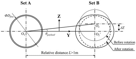

Figure 5.
Sketch to illustrate misalignment tolerance ΔZ with payload rotation.
ΔRX is limited by mechanical interference between the pointer and the drogue. There is a 3 mm gap between the pointer and the relative pointer groove in the drogue, while the radius from the X axis is 55 mm. Considering the mirror symmetry of pointer assembly, ΔRX is calculated as the rotation angle of ±3.1°.
On account of the clearance fit of probe–drogue architecture, ΔRY depends on the fine fit with a length of 10 mm. Then, ΔRY equals its arctangent function of ±1.1°. ΔRZ is analyzed in the same way as ΔRY. The drogue hole in set B has a waist shape, and its rough fit clearance along the Y axis is 3 mm. Since the total fit length of the rough fit and the fine fit is 95 mm above the docking plane, its arctangent function of 1.8° represents ΔRZ.
In summary, the geometrical boundary conditions of misalignment tolerance with univariate analysis are shown in Table 2.

Table 2.
Geometrical misalignment tolerance design for set B with univariate analysis.
Therefore, by means of the floating–fixed-end configuration and rough–fine fit design, the maximum designed tolerance of the double-point docking mechanism is ΔY = ±2.7 mm and ΔRX = ±3.1°, which is better than the low-impact docking mechanism of the International Space Station. This design potentially provides theoretical guidance for the design of EVA docking mechanism with large misalignment tolerance.
3. Numerical Simulations
3.1. Dynamic Analysis
To analyze the characteristics of handheld docking mechanism, dynamic simulations are conducted in the Adams Software 2020. The simulations concentrate on the operating force and the related preload during the whole dynamic procedure, including insertion, soft connection, locking, unlocking, and unlocked-maintaining-state entering and relieving force.
The geometrical model of the handheld docking mechanism is exactly reproduced in the Adams Software. The probe and the drogue are set with the same material of aluminum to match the thermal deformation. The grab-part is mainly made from titanium to enhance its strength. All the sliding and revolving pairs are lubricated by molybdenum disulfide. Stiffness, friction coefficients, and damping coefficients are chosen consistently with the material. The metal–metal collisions are applied as solid-to-solid ones.
3.1.1. Insertion Process
During insertion process, astronauts hold the grab-part with one hand to move the payload towards the spacecraft while the other hand should hold the handle or other fixed positions to provide a stable operation condition, as shown in Figure 6a. Since the probe–drogue configuration is composed of two-stage clearance fit, self-locking torque needs to be verified to ensure a smooth insertion process. As depicted in Figure 4b, lengths L2 and L1 should satisfy the following relationship to prevent self-locking:
where μ stands for the coefficient of kinetic friction as 0.1 after lubrication, and the ratio of L2 to L1 exceeds 2 as designed. The result guarantees the absence of self-locking risk due to eccentric bending load within the manual insertion procedure.
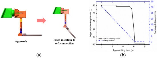
Figure 6.
Dynamic analysis of the insertion process with (a) the Adams Software simulation model and (b) the simulated angle of the operating handle changing with time.
The insertion process is simulated to check the effectiveness of automatic capture until a soft connection, which greatly satisfies the requirements of human factors engineering. In the simulation case, the passive probe is fixed, and the active drogue is approaching at a speed in the curve of Figure 6b. The drogue is initially static when it is supported by the robotic arm and astronauts start EVAs to hold the mechanism. Then, it approaches the probe at around 5 mm/s and remains static after the soft connection. The angle of the operating handle is defined in the same way as in Figure 4c,d, and it maintains 90° before the soft connection. From the curve of angle in Figure 6, the operating handle rotates from the horizontal position (θ = 90°) to θauto = 41° while the latch-spring automatically pushes the latch into the thinner docking shaft to prevent the escape of payload. The angular velocity of the operating handle increases from near 0 to around 95°/s between 5.65 s and 6.2 s to achieve the anti-escape function and achieve the soft connection, satisfying the EVA human factors engineering of one-hand operation and hand change.
3.1.2. Locking Process
According to the human factors engineering requirements, astronauts usually hold the middle part of the operating handle. In this case, the arm of the manual operating torque is represented by c in Figure 4d. The angle θ of the operating handle decreases from θauto to θlock by manual force. The structure of slider-crank mechanism correspondingly varies, and we use angle α and β to describe its force amplification effect. The disk springs are compressed by the slider-crank mechanism, and the locking torque can be calculated by the following formula:
where k stands for the stiffness of disk springs, and xdspr-prcp represents the pre-compression deformation of disk springs during the docking mechanism assembly by displacement control. In this case, the handheld docking mechanism uses tens of disk springs to control total stiffness 70 N/mm ≤ k ≤ 95 N/mm and chooses different thicknesses of the screw gasket to adjust xdspr-prcp. The force-amplifying mechanism is passively driven without motors, and its main power source comes from the compression force of the disk spring components between 500 N and 525 N. This compression force is divided into two parts, nearly half of which is provided by the initial compression force, and the other half is generated by the astronaut operation, including rotating the operating handle, the slider-crank mechanism generating displacement, and compressing the disk spring components. In addition, αauto and βauto correspond to the angles at the soft connection stage. As for the designed geometry, it can be derived that β = θ − 15° and α = arcsin (a/b × sin β).
The relationship between the operating angle and the operating torque is numerically simulated where the operating handle is set as a constant speed of 10°/s in clockwise rotation. The simulation results are compared with theoretical analysis, and they are plotted together in Figure 7, indicating great consistency.
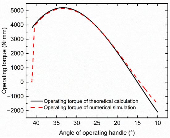
Figure 7.
Theoretical and simulated relationship between angle of operating handle and operating torque in the locking process.
The maximum operating torque of 5154 N·mm occurs at θ ≈ 33° with a maximum locking force of 32.2 N when the length of operating handle c equals 160 mm. The locking force can be further increased or decreased according to the EVA requirements by simply adjusting the length of the operating handle, which is the length of the lever arm. This locking force satisfies the performance requirement R5. Due to the load delay in the finite element software, the operating torque increases from 0 in the beginning.
In the early stage of the locking process, the operating torque shows an increasing trend due to the increase in compressed disk spring force. When it gradually approaches the dead point at θ = 15° of the slider-crank mechanism, the operating torque shows a downward trend afterwards. After the dead point, the disk spring force reverses from resistance to operating power, so the operating torque changes from positive to negative.
The rigid connection is established by the locking force, and the axial preload is imposed on the docking planes of the probe and drogue. Based on force analysis on the docking shaft and latch, combined with Equation (3), the formula of axial preload is derived as follows.
By substituting all the parameters, the curve of axial preload with operating-handle angle is plotted in Figure 8 to compare with the simulation results. Further investigation on the parameter sensitivity, including the slider-crank mechanism geometric parameters a and b, the pre-compression deformation xdspr-prcp of the disk spring components, the inclined angle γ of the latch sidewall, and the stiffness k of disk spring components, will be conducted in the future to make the simulation more valuable to the mechanism design.
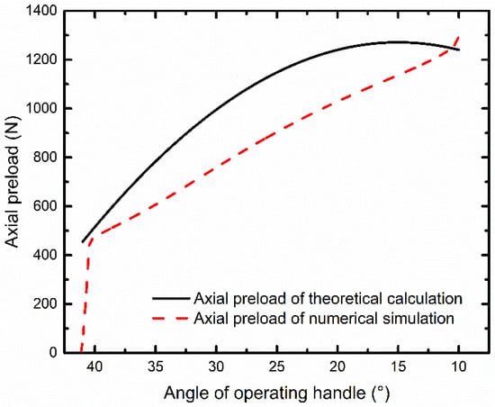
Figure 8.
Theoretical and simulated relationship between angle of operating handle and axial preload in the locking process.
The calculated axial preload increases as the operating handle rotates clockwise and reaches a maximum value of 1300 N at the dead point position of θ = 15°. It amplifies the compression force of disk spring by 2.6 times through the inclined sidewall in the thinner docking shaft. The structural connection is established, and the axial preload fulfils functional requirements R2 with three times the margin. It is pointed out that, after the dead point position of the slider-crank mechanism, the axial preload remains large enough for a rigid connection.
Compared with the theoretical calculation, the numerical simulation differs in the curve type and intersects at the same final preload. This is caused by the solid-to-solid collision setting between the thinner docking shaft of the passive probe and the latch. The structural deformation on the inclined sidewall contact surface is replaced by the slight displacement of the latch and leads to the discrepancy. Further investigation on the optimization of the simulation model will be addressed in our future work, assisting to reduce inconsistencies and making the simulation more realistic.
3.1.3. Unlocking Process
The unlocking process is, to some extent, opposite of the locking operation. The simulated relationship between the operating torque and the angle of operating handle is depicted in Figure 9. The operating handle is set as rotating counterclockwise at a constant speed of 10°/s and during the whole process. The maximum operating torque of 4789 N·mm occurs at θauto = 41° with a maximum unlocking force of 29.9 N at the operating handle c = 160 mm, which meets the performance requirement R5.
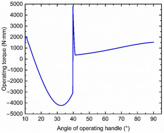
Figure 9.
Simulated relationship between angle of operating handle and operating torque in the unlocking process.
As the handle angle increases from θlock = 10° to the dead point position of θ = 15°, the operating torque is exactly the reverse of that in the locking process in Figure 7. Then, from the dead point position to θauto = 41°, the disk spring compression force turns out to be the driving force. The simulated unlocking torque is below zero, indicating that manual force is applied to steady the handle rotation. There is a sudden change in unlocking torque at θauto = 41° due to the separation of the latch and thinner docking shaft. The structural deformation has been formed under the axial preload at the inclined sidewall contact surface of the latch and thinner docking shaft. With the handle rotation, the separation causes a sharp peak of transit force. However, in practice, the inertia effect of the operating handle will reduce this effect. Future investigation on the optimization of the simulation model will be conducted to reflect a more realistic response of the dynamic process. Afterwards from θauto to 90°, the operating torque slowly increases to withstand the latch-spring force until the operating handle is back to the initial horizontal position.
3.1.4. Unlocked-Maintaining-State Entering and Relieving Process
The operating torque drives the roller climbing the wedge to enter and relieve the unlocked-maintaining-state with counterclockwise and clockwise rotations, respectively. The upper and lower slopes of the wedge have different angles against vertical. If the upper slope angle of wedge is too small, it will be difficult to maintain the unlocked state considering spacecraft movement, docking impact, and so on. Otherwise, if the upper slope angle is too large, the astronaut operating force for releasing the unlocked state tends to exceed human factors engineering requirements. Therefore, with iterative analysis of various angles, the upper slope angle is set at 87°. The dynamic analysis model and simulated operating torque of entering and relieving the unlocked-maintaining-state are shown in Figure 10. The operating handle is set rotating at a constant speed in opposite directions in both processes.
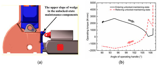
Figure 10.
Dynamic analysis of the unlocked-maintaining-state entering and relieving process with (a) the Adams Software simulation model and (b) the simulated relationship between the angle of operating handle and operating torque.
During the entering procedure, the maximum operating toque reaches almost 2800 N·mm with the operating force of 17.5 N at the operating handle c = 160 mm. When passing the protrusion of wedge, the operating torque reduces from maximum to near zero and then keeps increasing to provide constant-speed rotation. The final peak is caused by the mechanical position limit. In the relieving process, the maximum value of around 4800 N·mm occurs at the starting position with a sudden peak to overcome the contact deformation. This corresponds to the operating force of 30 N at the operating handle c = 160 mm. When approaching the protrusion of wedge, the operating torque rapidly rises and subsequently reduces gradually to below zero because the latch-spring also contributes to the handle rotation. The simulated unlocked-maintaining-state entering and relieving forces both satisfy the performance requirement R5.
3.2. Static Analysis
To prevent plastic deformation or failure of key components of the handheld docking mechanism under load, the static analysis of critical components is conducted using the finite element method. The static analysis is based on the above simulation and theoretical dynamic analysis results, taking into account friction and lubrication factors.
The geometric models of these critical mechanical parts are established in the ANSYS Software 2020, including the passive probe, the housing base, the latch components, the slider-crank mechanism, etc. The component materials, elastic modulus, yield strength, and Poisson’s ratio are set according to the mechanism design. The models are separately tetrahedral meshed, with an overall mesh size of 3 mm. The boundary constraint and load excitation areas are locally refined to a mesh size of 1 mm. Fixed constraints are performed based on the assembly relationships between various components of the handheld docking mechanism and their relative interactions with the cabin, payload, and astronauts. Load excitation of each component derives from the dynamic analysis.
The static analysis of the passive probe as an example. The geometric model is divided into tetrahedral meshes, and the mesh is encrypted at the through-hole of the thinner docking shaft with the mesh size of 1 mm. According to the mechanism design and dynamic analysis, fixed constraint is applied to the mounting interface of the passive probe. A preload of 1319 N is applied perpendicular to the 7° inclined sidewall at the contact surface between the passive probe and the latch. A maximum locking force of 1303 N horizontally to the left and 266 N vertically downward is applied. By finite element calculation, the maximum stress is 31.55 MPa, which is far lower than the yield strength of aluminum alloy. The maximum deformation is 0.01486 mm. Both the maximum stress and deformation meet the on-orbit application requirements. The simulation model and results are depicted in Figure 11.

Figure 11.
Static analysis of the passive probe with (a) the meshed model, (b) the load application, and (c) the stress distribution simulation result.
Static analysis is conducted on all key load-bearing and force-transmitting parts. The maximum stress occurs in the connecting screws of the slider-crank mechanism. Due to the human factors engineering requirements on the EVA grab size restriction, the connecting screws are specially designed. The maximum local stress is 128 MPa, which is only one-sixth of the yield strength of the selected titanium alloy material. This ensures that the design of the handheld docking mechanism satisfies the static requirements and is suitable for the on-orbit docking of large-scale payloads.
3.3. Kinematic Analysis
The operating range of the docking mechanism is generally regarded as the maximum values of axial, lateral displacement and angular misalignment, which still enable the whole docking process. In this case, the criteria of successful docking are adopted as follows: (1) the operating force below 100 N; (2) the deviation in locking depth h1 remains less than 3 mm; and (3) axial preload above 1000 N. These criteria meet the requirements R2 and R5 and can be quantitatively measured. From the perspective of kinematics, these values not only depend on the mechanism geometry, but also are associated with the human factors engineering and connection stiffness. The simulated operating range can be set as the preliminary constraint for docking conditions.
A series of numerical kinematic simulations are performed with different misalignments of six DoFs through the control variate method. Two schemes concentrating on different probe–drogue combinations are investigated, as follows.
3.3.1. Single-Probe–Drogue Scheme
Owing to the waist shape of the drogue hole in set B and different fit clearance for either set, docking simulations of univariate misalignment tolerance are implemented for a single probe–drogue. The geometries of the docking mechanism are directly imported into the software as in the chapter “Dynamic analysis”. Based on the relativity of motion and complexity of active parts, the drogue is held at a fixed position while the probe is mounted on a frame of six DoFs, moving towards the drogue. In this way, the univariate misalignment is simulated, and maximum values are explored separately. The operating force, locking depth, and imposed preload are measured in each condition when the operating handle is set to rotate at a constant speed. The cross-section schematic of set A docking misalignment is shown in Figure 12 as an example, and the kinematic simulation results are listed in Table 3.

Figure 12.
Cross-section schematic of the misalignment tolerance simulation with the univariate analysis of ΔRZ (dashed lines) for set A as an example of a single-probe–drogue scheme.

Table 3.
Simulated misalignment tolerance by univariate analysis in single-probe–drogue scheme.
It is clear that set B has a relatively larger operating range. Compared with Table 2, the boundary condition of ΔX is consistent with the locking latch geometrical analysis and ΔY agrees with the clearance design. The difference in ΔZ values indicates that the latch structure assists in decreasing the pitch and roll angle of the assembled payload and enhancing the perpendicular pointing accuracy. The tolerance of ΔRX is the same as designed in one direction and broader than geometric analysis in the other direction because it is constrained by the mechanical collision between the pointer and the groove of the drogue sidewall. The groove leaves more space in one rotation direction. The angular misalignment of ΔRY and ΔRZ greatly influences the locking length and imposed preload; therefore, the simulated tolerance is stricter than the geometrical analysis, which fails to consider the factor of axial preload. The inclined sidewall of latch accounts for the asymmetry of ΔRY. The above results evaluate the misalignment tolerance of a single set and lay the foundation for a dual-point scheme simulation.
3.3.2. Dual-Probe–Drogue Scheme
The second type of kinematic simulation not only focuses on the relative misalignment between set A and set B, but also investigates the whole-structure misalignment. In this case, the relative misalignment is defined as the relative change in attitudes and positions between probe A and probe B (also applies to drogue A and drogue B). In addition, the whole-structure misalignment assumes the ideal attitude and position between probe A and probe B (same for drogue A and drogue B), and gives constraints for dual-point docking by two astronauts. This is significantly different from the conventional single-point docking mechanism and assists to understand dual-point docking strategies as well as constraints.
The relative misalignment considers the deformation caused by inner air pressure, temperature variations, on-orbit loads, and so on. To simplify the misalignment conditions, drogues A and B are set as fixed, and there is no relative change in attitudes and positions between them. All the relative changes are transformed to probe B, which is held at a hinge of six DoFs, with a certain stiffness to represent a realistic circumstance, as theoretically analyzed in the chapter “Misalignment tolerance design”. According to the relativity of motion, the passive probes are pushed towards the drogues with operating force, as depicted in Figure 13a. The univariate simulated results are shown in Table 4, meeting the same criteria as for the single-probe–drogue scheme.
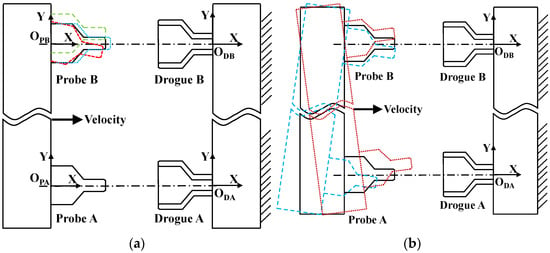
Figure 13.
Cross-section schematic of the univariate simulation for the dual probe–drogue scheme: (a) relative misalignment of ΔX (blue dashed lines), ΔY (green dashed lines), and ΔRZ (red dashed lines); (b) whole-structure misalignment.

Table 4.
Simulated relative misalignment tolerance for set B with univariate analysis in dual-probe–drogue scheme.
It is noticed that, compared with Table 3, the waist shape accounts for ΔY allowance, and ΔRX is the same as the boundary condition in the single-probe–drogue scheme. The relatively large ΔX tolerance ignores the gap of the docking plane and mainly considers three factors of imposed preload, locking depth, and operating force. The enhanced tolerance in ΔZ agrees with the theoretical analysis in the chapter “Misalignment tolerance design”, indicating that the static-floating-combined clearance design improves the dual-point docking adaptability due to the roll-angle rotation of payload. The simulated operating range of ΔRY and ΔRZ is broader than the single-probe–drogue scheme mainly because the enhanced misalignment is shared by both sets of the docking mechanism while it may influence the perpendicular pointing accuracy to some extent.
The whole-structure misalignment regards probes A and B as a whole and same for drogues A and B. The cross-section schematic of simulation structures is given in Figure 13b. Due to human factors engineering, it is feasible for astronauts to adjust the preliminary docking conditions visually or through palm contact force. Besides the above criteria of successful docking, in this scheme, operating torque is limited to less than 2000 N·mm with enough safety margin for when astronauts hold the grab-part to insert the mechanism. The simulations reveal that ΔRY and ΔRZ are at least ±30° and ±20°, respectively, which allow to visually adjust collaboration. The angular misalignment tolerance of ΔRX is ±1.5°, revealing that the whole-structure can be rotated until the thinner docking shaft fails to slide into the drogue hole. This provides sufficient space for astronauts to accomplish docking and reflects the significance of on-orbit cooperation.
4. Experimental Results
4.1. Dynamic Experiments
Dynamic analysis is valuable to characterize the operating force during the whole process to satisfy the human factors engineering. The dynamic experiments are conceived to validate the proposed mechanism design and numerical simulations.
The docking mechanism is manufactured with a weight of 7.5 kg and assembled and tested based on the design in Figure 14. The disk springs are pre-compressed by the adjusting shims to adapt to the deviation in disk spring stiffness. The disk spring force is controlled by the total amount of compression to guarantee the imposed axial preload. The manual operating force is measured by force sensors mounted in the middle of the grab-part and operating handle. In order to eliminate the gravity influence on motion components, the XOZ plane of the mechanism is kept at a level. In the high–low-temperature test chamber, the passive probe is fixed on the test tooling, and the active drogue parts are zero-gravity-unloaded by the suspension rope to balance the gravity during operation. The experimental setup is shown in Figure 15. Several sets of measurements in high–low-temperature conditions of −55 °C, +75 °C, and room temperature 25 °C are conducted to test the influence of temperature on the operating force.

Figure 14.
Photos of all operation statuses of handheld docking mechanism prototype.
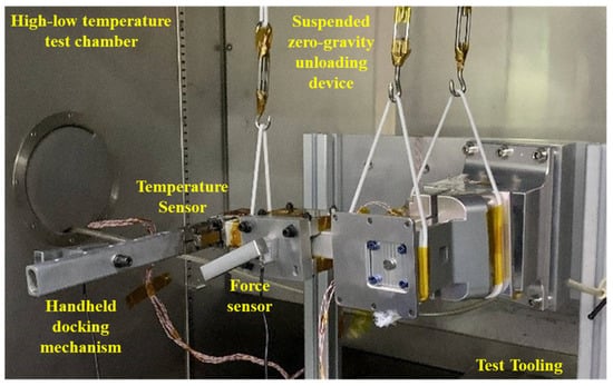
Figure 15.
Picture of experimental setup for measurement of operating force during whole process under high–low-temperature condition.
Two force sensors are calibrated in advance, and measured tension is defined to be positive. Operating force is specially imposed perpendicular to force sensors, and the arm c of the manual operating torque is around 160 mm. Temperature sensors are deployed to measure the temperature of docking mechanism.
The dynamic experiments replicate the conditions of on-orbit assembly operation. The drogue is slowly pushed towards the fixed probe until a soft connection achieved. Subsequently the locking and unlocking procedures continue. The rotation speed of operating handle is not always constant since manual operation requires response time and adjustment. Figure 16 represents the typical curve of measured operating force over time during the whole operation process and the trend of operating-handle force curve is coincident with the previous analysis.
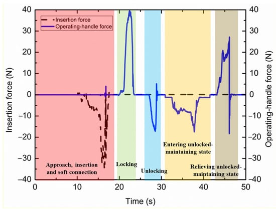
Figure 16.
Typical curve of measured operating force over time during whole operation process.
The insertion resistance not only depends on the spring-damper force, but also is relevant to docking misalignment. In dynamic experiments, when the chasing drogue is not strictly aligned during the approach, the insertion force is over 20 N at room temperature due to rebounds and friction. In contrast, the ideal insertion force without misalignment is tested to be less than 10 N. When the mechanism experiences a −55 °C low-temperature condition, the measured insertion resistance rises up to around 50 N due to the friction coefficient increase at docking impact. Faced with a 75 °C high-temperature environment, insertion force in test dramatically drops down to 3.4 N, also caused by the decrease in spring stiffness.
The peak value of the measured locking force, i.e., 39.7 N, at room temperature is slightly larger than analyzed 32.2 N on account of non-ideal lubrication and friction, still ensuring safety margin on the human factors engineering requirements. The locking force reduces to 24 N at a high temperature of 75 °C and remains basically unchanged at a low temperature of −55 °C, which reflects the effectiveness of lubrication of sliding and rotating pairs.
Furthermore, the measured unlocking force of 17.3 N is larger than the simulation result of 10 N. This is because the unloading efficiency of gravity suspension is below 100%, and the tangential force at the contact surface immediately eliminates the structural deformation between the latch and the thinner docking shaft. This contributes to the operation strategy that appropriate shaking of the mechanism assists to ease the unlocking operation. The unlocking force remains relatively stable under 75 °C and −55 °C to validate the unlocking process in a wide temperature range.
In the unlocked-maintaining-state relief process, the operating handle returns to the horizontal position when the operating force gradually increases at climbing the wedge and dramatically drops due to the latch-spring force. There is an impact force in the end as the motion of latch is constrained by the spring-damper components. As a result, the measured operating force curve proves to be a validation of the numerical simulation results.
4.2. Kinematic Experiments
The kinematic experiments are designed and conducted to evaluate the misalignment allowance of the proposed mechanism capacity. Three different experiments are conceived including the single-probe–drogue misalignment scheme and the relative and whole-structure misalignment of dual-point probe–drogue schemes.
4.2.1. Single-Probe–Drogue Scheme
The operating range of the single-probe–drogue scheme is tested in the experimental setup, similar to that in dynamic experiments. The passive probe is fixed horizontally and the active drogue moves towards it by manual operation with different initial misalignment conditions while hanging. The attitude and position misalignment of active drogue is measured by a vision system and image recognition and processing techniques. The measurement error of the vision system is less than 0.2 mm in position and below 0.3° in angle. For simplicity, the adopted success criteria include operating force below 100 N and locking depth within the range of h1 ± 3 mm. The experiments are implemented by univariate variation of six DoFs for the active drogue. Table 5 represents the worst initial conditions to achieve successful docking. The univariate misalignment tolerance of ΔY and ΔZ for set A is designed as small as the vision system resolution; therefore, it is not tested to protect the mechanism.

Table 5.
Measured univariate misalignment tolerance in single-probe–drogue scheme.
The experimental results indicate consistency with the simulation analysis in Table 3. The assessed misalignment tolerance of ΔX, ΔRY, and ΔRZ is slightly larger than that of the previous simulation thanks to local deformation on the contact surface of the docking plane and measurement error. Compared with previous analysis, the difference in ΔRX is caused by assembly errors of the pointer and the deformation of the inclined sidewalls between the latch and thinner docking shaft. With respect to ΔY and ΔZ of set B, the tested lateral displacement tolerance agrees with the mechanism design. The evaluated values are comparable to the sensor resolutions and allow further speculation for true values.
4.2.2. Dual-Probe–Drogue Scheme
To characterize the behavior of dual-point misalignment tolerance, the corresponding kinematic experiments are representative of the realistic on-orbit docking scenario. Similar to the kinematic simulation, the dual-probe–drogue scheme consists of the relative misalignment tolerance experiment and whole-structure misalignment allowance test.
The experimental setup for relative misalignment tolerance is specially designed to fulfil the human factors engineering requirements. For simplicity, all the relative misalignments are converted to probe B and the other docking elements are assumed ideal as kinematic analysis. The passive probe A is rigidly connected with a support beam held by the support vehicle. Probe B is mounted on a Stewart parallel platform of six DoFs at the designed relative position and attitude. The Stewart platform has the position-adjustment range of ±30 mm in the X direction and ±55 mm in the Y and Z axes with a 0.1 mm measurement error. It also contains the angular adjustment scope of ±7° around three axes with a resolution of 0.1°. The active drogues are structurally connected with the payload mock-up plate of over 200 kg as designed. Triaxial attitude sensors are placed on it to characterize the attitude angle of active drogues. Considering the zero-gravity environment on orbit, the active mechanism is suspended by a robotic arm, as depicted in Figure 17. The robotic arm is configured in the follow-up damping mode with a resistance of below 20 N and 2 Nm and limits of 60 mm/s and 10°/s. Closed-loop motion control is implemented in the robotic arm to fully eliminate the gravity influence in different situations. The relative position and attitude of probe B is adjusted univariately, and the payload is manually pushed towards the probes. The success criteria are the same as the single-probe–drogue scheme.
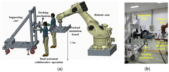
Figure 17.
(a) Schematic sketch and (b) picture of experimental setup for misalignment tolerance measurement in dual probe–drogue scheme.
The measured relative misalignment tolerance is presented in Table 6. The allowance of ΔY, ΔZ, and ΔRX is consistent with numerical simulations when influencing factors of precision and resolution are taken into consideration. The displacement tolerance of ΔX is more realistic than simulation because the gap of the docking plane is tested to ensue less than 0.05 mm. ΔRY is a little larger than the numerical result because the connection stiffness between the docking mechanism and payload mock-up plate is lower. ΔRZ is slightly smaller compared with that of the previous analysis because the contact between the inclined sidewalls of the latch and docking shaft changes from an ideal surface contact to an actual line contact.

Table 6.
Measured relative misalignment tolerance for set B with univariate analysis in dual-probe–drogue scheme.
Different from the experimental setup for relative misalignment tolerance, the experimental prototype for whole-structure misalignment removes the Stewart parallel platform. The relative position and attitude of sets A and B are precisely adjusted as ideally proposed. The vision system and success criteria are applied as above to measure the docking range. The operation process is similar to testing the traditional single-point docking misalignment tolerance. Experimental measurements indicate that ΔRX is more than ±1.5°, which agrees with simulation analysis. ΔRY and ΔRZ prove at least ±10° and ±15°, respectively, where the drag torque of robotic arm accounts for the smaller range than numerical simulation. However, the measured docking range is still large enough for dual-astronaut cooperation and visual adjustment when docking.
Furthermore, the evaluation of the mechanism operation under temperature variation conditions, especially at different locking and unlocking temperatures, is also an important verification of the misalignment tolerance design. A further study of this influence will be addressed in the future work.
The pointing accuracy of the payload mock-up plate is also tested in the ideal position and attitude of sets A and B to ensure the performance requirement R4. The payload mock-up plate is suspended vertically by the zero-gravity gas-floating platform, and other experimental setup is established in a similar way as described above. Based on several docking experiments, the pitch and roll angles of the perpendicular pointing accuracy for the assembled payload are both less than 0.05°, guaranteeing the high-precision attitude to obtain payload performance.
As a result, we have comprehensively characterized the performance of the proposed handheld docking mechanism. Compared with the existing docking schemes as shown in Table 7, the handheld docking mechanism is the lightest with the largest angular misalignment tolerance, being the most suitable for EVAs. It has a relatively high load-to-self-weight ratio to demonstrate a promising capacity of force amplification and load bearing. The scale guarantees its adaptability to on-orbit service of large-scale payloads.

Table 7.
Comparison of proposed handheld docking mechanism with existing payload docking mechanism schemes.
4.3. On-Orbit Application
Faced with the demand of on-orbit docking and assembly of large-scale payloads by EVAs, the handheld dual-point docking mechanism proposed in this paper was on-orbit deployed in China’s Space Station.
The docking mechanism was designed, analyzed, manufactured, tested, and verified as described in this paper, and eventually, it was launched into China’s Space Station. As shown in Figure 18a, the Shenzhou 15 crew, with the cooperation of ground staff and astronauts in the cabin, accomplished the third extravehicular activity in March 2023. They utilized the space station’s robotic arm, in accordance with the operation process of the docking mechanism, in steps of approach, insertion, soft docking, and locking depicted in Figure 18b. The rigid structural connection of the large-scale payload between the active drogues and passive probes was successfully established, satisfying the on-orbit performance requirements for the docking mechanism.
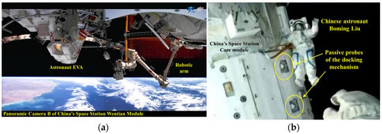
Figure 18.
(a) Public photos of the third EVAs of the Shenzhou 15 crew. (b) Reported pictures of the passive probes of the proposed handheld dual-point docking mechanism applied in China’s Space Station.
The analysis, design, manufacturing, testing, and verification methods of the handheld dual-point docking mechanism have been on-orbit verified and applied. This pioneers a new way for on-orbit service of large-scale payloads through EVAs, and lays a technical foundation for the on-orbit construction of large spacecraft in the future.
5. Conclusions
In summary, we present the design, functionality, and on-orbit application of a handheld dual-point docking mechanism. The proposed docking mechanism is compatible for multi-person manually docking and assembly of large-scale payloads that exceed the launch envelope. It achieves the functional decoupling of docking, locking, unlocking, and separation throughout the whole process, and satisfies the human factors engineering for astronauts to change hands and operate with one hand and limited force. This technology paves a road to the promising on-orbit service of large-scale payload assembly, maintenance, and replacement.
The conceived mechanism is described in detail. Mechanism design, simulation, and experimental results are performed to characterize its performance. Adapting to large-scale payloads of the large-span docking plane, the dual-point docking system is applied, and the human factors engineering requirements are specially satisfied by a series of designs. The reliable probe–drogue configuration is adopted to enable orientation, and different probe–drogue fit clearance ensures the docking accuracy. The slider-crank mechanism amplifies the operating force. Disk spring components, instead of traditional motors, provide compression force to impose axial preload and achieve the structural connection. According to mission plan and mechanism requirements, the docking sequence of on-orbit operation is designed as approach, insertion, soft connection, locking, unlocking, unlocked-maintaining-state entry, separating, and unlocked-maintaining-state relief. In terms of operating force, dynamic simulations and experiments are presented to prove the mechanism behavior fulfilling requirements. To ensure the structural strength of the load-bearing and force-transmitting parts, static analysis is conducted to calculate the stress distribution. Based on the criteria of successful docking, numerical simulations are implemented to estimate three types of initial boundary conditions, including single-probe–drogue misalignment, relative misalignment, and whole-structure misalignment of the dual-probe–drogue scheme. Kinematic experiments are conducted to demonstrate the simulation and theoretical results by comparing axial, lateral displacement, and angular misalignment tolerance of six DoFs. All kinds of influencing conditions, including assembly errors, structural deformations, temperature variations, on-orbit loads, and manual operation errors, are confirmed to fall into the mechanism operating range. This validates the misalignment tolerance design of the dual-point docking system. The perpendicular pointing accuracy of the assembled docking mechanism is measured to guarantee the payload’s high performance. Eventually it is launched into China’s Space Station and implemented by the Shenzhou 15 crew to achieve its first on-orbit application.
The proposed mechanism contributes to the breakthrough of on-orbit manually docking and assembly area and provides useful input for docking strategies. An investigation on it indicates the appealing potential of on-orbit service application. Future development comprises a multi-functional mechanism able to fold, deploy, and dock to further reduce the envelope size and that is also suitable for EVAs.
Author Contributions
Conceptualization, R.H. and B.W.; methodology, Y.B.; validation, R.H. and B.W.; formal analysis, Y.B.; data acquisition, R.H. and B.W.; writing—original draft preparation, R.H., W.L. and B.L.; writing—review and editing, R.H., W.L. and B.L. All authors have read and agreed to the published version of the manuscript.
Funding
This work is supported by the Research Program of China Electronics Technology Group Corporation, 38th Research Institute (WG00110727T1WXY), CNPC Innovation Found (2025DQ02-0508), Science Foundation of China University of Petroleum Beijing (No. 2462024YJRC015), and Qian Xuesen Youth Innovation Fund of China Aerospace Science and Technology Corporation ([2022]No. 34).
Data Availability Statements
Some or all data, models, or codes that support the findings of this study are available from the corresponding author upon reasonable request.
Conflicts of Interest
The authors declare no conflicts of interest.
References
- Duke, H. On-Orbit Servicing; Center for Strategic and International Studies: Washington, DC, USA, 2021. [Google Scholar]
- Reed, B.B.; Townsend, J.A.; Thronson, H.A., Jr.; Ahmed, M.; Whipple, A.O.; Oegerle, W.R. Early results from NASA’s assessment of satellite servicing. In Space Telescopes and Instrumentation 2010: Optical, Infrared, and Millimeter Wave; SPIE: San Diego, CA, USA, 2010; Volume 7731, pp. 46–52. [Google Scholar]
- Shayler, D.J.; Harland, D.M. The Hubble Space Telescope: From Concept to Success; Springer: Berlin/Heidelberg, Germany, 2015. [Google Scholar]
- Friend, R.B. Orbital express program summary and mission overview. In Sensors and Systems for Space Applications II; SPIE: San Diego, CA, USA, 2008; Volume 6958, pp. 11–21. [Google Scholar]
- Barnhart, D.A.; Rughani, R. On-orbit servicing ontology applied to recommended standards for satellites in earth orbit. J. Space Saf. Eng. 2020, 7, 83–98. [Google Scholar] [CrossRef]
- Wang, Z.; Wang, P.; Duan, J.; Tian, W. Review of On-Orbit Assembly Technology with Space Robots. Aerospace 2025, 12, 375. [Google Scholar] [CrossRef]
- Hakima, H.; Emami, M.R. Deorbiter CubeSat system engineering. J. Astronaut. Sci. 2020, 67, 1600–1635. [Google Scholar] [CrossRef]
- Medina, A.; Tomassini, A.; Suatoni, M.; Avilés, M.; Solway, N.; Coxhill, I.; Paraskevas, I.S.; Rekleitis, G.; Papadopoulos, E.; Krenn, R.; et al. Towards a standardized grasping and refuelling on-orbit servicing for geo spacecraft. Acta Astronaut. 2017, 134, 1–10. [Google Scholar] [CrossRef]
- Uchida, A.; Uno, K.; Yoshida, K. Space debris reliable capturing by a dual-arm orbital robot: Detumbling and caging. In Proceedings of the 2024 International Conference on Space Robotics (iSpaRo), Luxembourg, 24–27 June 2024; IEEE: New York, NY, USA, 2024; pp. 194–201. [Google Scholar]
- Bigdeli, M.; Srivastava, R.; Scaraggi, M. Mechanics of space debris removal: A review. Aerospace 2025, 12, 277. [Google Scholar] [CrossRef]
- Li, W.J.; Cheng, D.Y.; Liu, X.G.; Wang, Y.B. On-orbit service (OOS) of spacecraft: A review of engineering developments. Prog. Aerosp. Sci. 2019, 108, 32–120. [Google Scholar] [CrossRef]
- Smith, T.K.; Akagi, J.; Droge, G. Model predictive control for formation flying based on D’Amico relative orbital elements. Astrodyn 2025, 9, 143–163. [Google Scholar] [CrossRef]
- Li, J.Y.; Emami, M.R. A geometric approach to optimal motion planning for close-range rendezvous and synchronization. In Astrodyn; Springer: Berlin/Heidelberg, Germany, 2025. [Google Scholar]
- Sun, X.; Wang, Y.; Su, J.; Li, J.; Xu, M.; Bai, S. Relative orbit transfer using constant-vector thrust acceleration. Acta Astronaut. 2025, 229, 715–735. [Google Scholar] [CrossRef]
- Boesso, A.; Francesconi, A. Arcade small-scale docking mechanism for micro-satellites. Acta Astronaut. 2013, 86, 77–87. [Google Scholar] [CrossRef]
- Choi, J.; Jung, J.; Lee, D.; Kim, B. Articulated linkage arms based reliable capture device for janitor satellites. Acta Astronaut. 2019, 163, 91–99. [Google Scholar] [CrossRef]
- Li, G.; Xu, P. Design and analysis of a deployable grasping mechanism for capturing non-cooperative space targets. Aerosp. Sci. Technol. 2020, 106, 106230. [Google Scholar] [CrossRef]
- Zhang, X.; Liu, Q.; Ma, X.; Gong, W.; Wang, W. Design and analysis of a large tolerance docking mechanism. Acta Astronaut. 2024, 221, 121–141. [Google Scholar] [CrossRef]
- Xu, C.; Liu, G.; Li, C.; Zhang, X.; Zhao, J. Optimization of low impact docking mechanism based on integrated joint design and task-oriented force ellipsoid index. Int. J. Mech. Mater. Des. 2024, 20, 195–208. [Google Scholar] [CrossRef]
- Nasa, R.; Jaxa, E. CSA: International Docking System Standard, Interface Definition Document; Revision E. 2016. Available online: http://internationaldockingstandard.com (accessed on 23 August 2025).
- Mohtar, T. Design and Modeling of a Space Docking Mechanism for Cooperative On-Orbit Servicing. Ph.D. Thesis, Politecnico di Torino, Turin, Italy, 2020. Available online: https://core.ac.uk/reader/234920700 (accessed on 23 August 2025).
- Lion, L.; Caon, A.; Olivieri, L.; Branz, F.; Francesconi, A. Kinematic tests on a docking mechanism for microsatellites. CEAS Space J. 2024, 16, 445–455. [Google Scholar] [CrossRef]
- Alizadeh, M.; Zhu, Z.H. A comprehensive survey of space robotic manipulators for on-orbit servicing. Front. Robot. AI 2024, 11, 1470950. [Google Scholar] [CrossRef] [PubMed]
- Li, H.; Liu, Q.; Wu, S.; Ma, W.; Wang, Z. Capturing dynamics of a space manipulator end-effector with snare capture and retract operations. Aerosp. Sci. Technol. 2023, 136, 108239. [Google Scholar] [CrossRef]
- Madonna, D.P.; Pontani, M.; Gasbarri, P. Berthing proximity maneuvers and trajectory planning of a space manipulator via Kane’s formulation. Acta Astronaut. 2024, 222, 674–691. [Google Scholar] [CrossRef]
- Man, W.; Li, X.; Zhang, Z.; An, J.; Zhang, G.; Yu, D. Research on space target on-orbit capturing methods. In Proceedings of the International Conference on Mechanical Design, Da Nang, Vietnam, 20–22 December 2021; Springer: Singapore, 2021; pp. 321–343. [Google Scholar]
- Zhao, Z.; Yin, Z.; Kang, Y.; Li, Z.; Ma, S.; Liu, Y. The design and implementation of extravehicular experiments support system for manned spacecrafts. In Proceedings of the 2023 2nd International Symposium on Aerospace Engineering and Systems (ISAES), Nanjing, China, 19–21 May 2023; IEEE: New York, NY, USA, 2023; pp. 53–58. [Google Scholar]
- Opromolla, R.; Grishko, D.; Auburn, J.; Bevilacqua, R. Future in-orbit servicing operations in the space traffic management context. Acta Astronaut. 2024, 220, 469–477. [Google Scholar] [CrossRef]
- Wang, X.; Zhang, Q.; Wang, W. Design and application prospect of China’s Tiangong Space Station. Space Sci. Technol. 2023, 3, 0035. [Google Scholar] [CrossRef]
- Kurnell, M.; Sharf, I. Model-based controllers for CubeSat ORU installation: A comparative study. Acta Astronaut. 2024, 223, 666–684. [Google Scholar] [CrossRef]
- Moore, S.K.; Gast, R.A. 21st century extravehicular activities: Synergizing past and present training methods for future spacewalking success. Acta Astronaut. 2010, 67, 739–752. [Google Scholar] [CrossRef]
- Braddock, M.; Szocik, K.; Campa, R. Ergonomic Constraints for Astronauts: Challenges and Opportunities Today and for the Future. In Proceedings of the Contemporary Ergonomics and Human Factors 2019, Stratford-upon-Avon, UK, 29 April–1 May 2019. [Google Scholar]
- Persson, J.; Dettmann, J. Columbus External Payload Facility-Architecture and utilisation. In Proceedings of the 2001 Conference and Exhibit on International Space Station Utilization, Cape Canaveral, FL, USA, 15–18 October 2001; p. 5068. [Google Scholar]
- Gianfiglio, G.; Dettmann, J.; Montrone, L.; Broyles, K.C. The Columbus External Payload Adapter (CEPA) Project: A Successful ESA/NASA Cooperation within the ISS Utilization Program. In Proceedings of the 55th International Astronautical Congress of the International Astronautical Federation, the International Academy of Astronautics, and the International Institute of Space Law, Vancouver, BC, Canada, 4–8 October 2004; p. T-2. [Google Scholar]
- Gao, C.; Kang, X.; Lei, H.; Xu, P.; Li, B. Design and analysis of a novel large-span two-fold deployable mechanism. Mech. Mach. Theory 2023, 186, 105352. [Google Scholar] [CrossRef]
- Debeule, K. Start documenting a [space] project—Requirements and constraints. In Proceedings of the REXUS/BEXUS Programme Selection Workshop, ESA, Noordwijk, The Netherlands, 14–18 December 2010. [Google Scholar]
Disclaimer/Publisher’s Note: The statements, opinions and data contained in all publications are solely those of the individual author(s) and contributor(s) and not of MDPI and/or the editor(s). MDPI and/or the editor(s) disclaim responsibility for any injury to people or property resulting from any ideas, methods, instructions or products referred to in the content. |
© 2025 by the authors. Licensee MDPI, Basel, Switzerland. This article is an open access article distributed under the terms and conditions of the Creative Commons Attribution (CC BY) license (https://creativecommons.org/licenses/by/4.0/).