Article

Hydrogen Supplementation in SI Engines: Enhancing Efficiency and Reducing Emissions with a Focus on Knock Phenomena

by
Saugirdas Pukalskas
*,
Alfredas Rimkus
,
Tadas Vipartas
,
Saulius Stravinskas
,
Donatas Kriaučiūnas
,
Gabrielius Mejeras
and
Andrius Ušinskas
Department of Automobile Engineering, Faculty of Transport Engineering, Vilnius Gediminas Technical University, Plytinės Str. 27A, 10105 Vilnius, Lithuania
*
Author to whom correspondence should be addressed.
Machines 2025, 13(7), 571; https://doi.org/10.3390/machines13070571
Submission received: 30 May 2025 / Revised: 20 June 2025 / Accepted: 29 June 2025 / Published: 1 July 2025
(This article belongs to the Special Issue Advanced Engine Energy Saving Technology)

Abstract

This study investigates the impact of hydrogen supplementation on the performance, efficiency, and emissions of a spark-ignition internal combustion engine, with a specific focus on knock phenomena. A Nissan HR16DE engine was modified to operate in a dual-fuel mode using gasoline (E95) and high-purity hydrogen. Hydrogen was injected via secondary manifold injectors and managed through a reprogrammable MoTeC ECU, allowing precise control of ignition timing and fuel delivery. Experiments were conducted across various engine speeds and loads, with hydrogen mass fractions ranging from 0% to 30%. Results showed that increasing hydrogen content enhanced combustion intensity, thermal efficiency, and stability. Brake specific fuel consumption decreased by up to 43.4%, while brake thermal efficiency improved by 2–3%. CO, HC, and CO2 emissions were significantly reduced. However, NOx emissions increased with higher hydrogen concentrations due to elevated combustion temperatures. Knock tendency was effectively mitigated by retarding ignition timing, ensuring peak in-cylinder pressure occurred at 14–15° CAD aTDC. These findings demonstrate the potential of hydrogen supplementation to reduce fossil fuel use and greenhouse gas emissions in spark ignition engines, while highlighting the importance of precise combustion control to address challenges such as knock and NOx formation.

1. Introduction

Hydrogen is emerging as a key enabler in the transition toward a low-carbon energy and transportation system. Its versatility allows it to be used across a wide range of sectors, including industry, electricity generation, and various modes of transportation. In the transport sector, hydrogen offers a viable alternative to fossil fuels, particularly in applications where battery-electric solutions are limited, such as heavy-duty vehicles, long-haul trucking, shipping, and aviation [1,2,3,4,5].
Hydrogen can be used directly in internal combustion engines with certain modifications, offering a faster pathway to decarbonization by utilizing existing engine technologies and manufacturing infrastructure. When used as a fuel, hydrogen produces no carbon dioxide emissions at the point of use and can significantly reduce other pollutants such as carbon monoxide, unburned hydrocarbons, and particulate matter. However, controlling nitrogen oxide (NOx) emissions remains a technical challenge and is typically addressed through lean combustion strategies and exhaust aftertreatment [6,7,8].
In energy systems, hydrogen plays a crucial role in balancing intermittent renewable energy sources. Excess electricity from wind or solar can be used to produce green hydrogen via electrolysis, which can then be stored and later used for electricity generation, industrial processes, or transportation fuel. This makes hydrogen a promising solution for long-term energy storage and for sectors that are otherwise difficult to decarbonize [9,10,11,12,13].
The development of green hydrogen—produced using renewable energy—further enhances its environmental benefits, reducing the carbon footprint of the entire fuel cycle. Advancements in hydrogen production, storage, and distribution technologies are making it increasingly cost-competitive and scalable. As infrastructure expands and regulatory support grows, hydrogen is expected to play an integral role in achieving global climate targets and transforming the energy landscape [8,9,14,15,16,17].
The United States positions hydrogen as a key solution in decarbonizing its economy, particularly in the transportation sector. The U.S. Department of Energy highlights hydrogen’s role in reducing greenhouse gas emissions, strengthening energy security, and supporting economic development [18]. Hydrogen internal combustion engines (ICEs) are gaining attention as a transitional technology, especially for medium- and heavy-duty vehicles. Federal initiatives and funding are advancing low-emission, high-efficiency hydrogen ICE development as a complement to fuel cell vehicles [19]. The National Clean Hydrogen Strategy and recent legislation, such as the Inflation Reduction Act, provide strong regulatory and financial support to scale clean hydrogen production and infrastructure across sectors [20,21].
The European Union considers hydrogen a critical element for reaching climate neutrality by 2050, targeting the production and import of 20 million tonnes of clean hydrogen annually by 2030 to decarbonize sectors like industry and transport [22,23]. Projects such as HYICE have explored the potential of hydrogen-powered ICEs, with EU regulations even classifying hydrogen ICEs with CO2 emissions below 1 g/kWh as zero-emission vehicles [24,25,26]. However, political disagreements remain: Italy, for instance, has voiced concerns over the 2035 ban on new internal combustion vehicles and supports alternatives like hydrogen and biofuels [27]. Meanwhile, European manufacturers such as Bosch and Ferrari are investing in hydrogen ICE technologies to maintain competitiveness and comply with strict emission targets [28,29]. While fuel cells remain a key focus of EU policy, hydrogen ICE development reflects the ongoing diversification of hydrogen applications in Europe’s decarbonization efforts.
South Korea is a global leader in fuel cell electric vehicle (FCEV) adoption, with approximately 29,500 units on the road by the end of 2022. The country aims to deploy around 3 million FCEVs, including passenger cars and commercial vehicles, by 2040. The HyNet consortium plans to build 100 new hydrogen refueling stations by next year [30,31,32,33].
China’s hydrogen economy is rapidly expanding, with over 350 hydrogen refueling stations as of early 2023, accounting for about 40% of the global total. The country plans to have over 1000 stations by 2030. In 2023, China sold approximately 6000 FCEVs, reflecting a 72% year-on-year increase [34,35,36].
Japan has been at the forefront of hydrogen technology, with a well-established hydrogen refueling infrastructure. As of 2024, there are at least 157 hydrogen fueling stations in the country, with plans to expand further [37,38,39,40,41].
The UK is expanding its hydrogen-powered public transport. Wrightbus plans to supply up to 1000 zero-emission buses across the UK, including hydrogen-powered models [42].
Hydrogen presents significant potential as an alternative fuel in internal combustion engines due to its ability to enhance engine efficiency and reduce harmful emissions. Various hydrogen production methods—such as electrolysis, biomass gasification, and chemical cracking of methanol and ammonia—provide different pathways for supplying hydrogen. When used in spark-ignition (SI) and compression-ignition (CI) engines, hydrogen enrichment can improve combustion performance while reducing emissions of CO, CO2, HC, smoke, and soot, and in some cases even NOx emissions. [6,43,44,45,46]. When hydrogen is blended with air, it forms a flammable mixture suitable for use in conventional SI engines. Unlike gasoline–air mixtures, hydrogen can sustain combustion even at very lean equivalence ratios, well below the flammability limits of gasoline. This ultra-lean combustion results in reduced flame temperatures, which, in turn, lowers heat losses to engine components, improves thermal efficiency, and decreases NOx emissions [47].
Nitric oxide (NO) and nitrogen dioxide (NO2) are the primary nitrogen oxides produced by combustion processes. During high-temperature combustion inside the engine cylinder, NO is predominantly formed through the Zeldovich mechanism. After being emitted into the atmosphere, NO undergoes oxidation and is gradually converted into NO2, resulting in a variable NO2/NOx ratio that depends on post-combustion chemical reactions and environmental conditions [48,49,50].
Overall, the use of hydrogen in SI internal combustion engines leads to higher combustion temperatures compared to conventional gasoline. This is primarily due to hydrogen’s faster flame propagation speed, higher lower heating value, and shorter autoignition delay [6,51,52]. These properties enable a more intense and efficient combustion process but simultaneously create favorable conditions for the formation of thermal NOx [53]. Elevated temperatures significantly increase NOx emissions unless additional emission control strategies—such as ignition timing optimization or EGR—are employed [54,55]. Therefore, although hydrogen is a carbon-free fuel that does not contribute to CO2 emissions, its application in SI engines requires precise combustion management to minimize its potential environmental impact [56].
Hydrogen-fueled engines operating near stoichiometric air–fuel ratios often experience abnormal combustion phenomena such as backfire, pre-ignition, and knock due to hydrogen’s distinct properties [57]. Controlling these issues remains a significant challenge. Verhelst et al. [58] argue that while hydrogen’s low ignition energy is frequently blamed for backfire, the actual cause may be linked more to the mixture’s high autoignition temperature and reduced quenching distance. Moreover, hydrogen engines contain very low particulate and deposit levels, minimizing the presence of traditional hot spots. Instead, the authors suggest that the combination of hydrogen’s reduced quenching distance and wide flammability limits enables combustion to occur in the piston top-land area—which may play a critical role in triggering abnormal combustion events [56]. As a result, the exact mechanisms behind hydrogen’s spontaneous and uncontrolled ignition remain under investigation.
Engine design plays a critical role in optimizing hydrogen use; effective fuel injection strategies, intake port geometry, and thermal management are essential to prevent abnormal combustion and achieve high thermal efficiency [7]. Research also highlights that hydrogen can be successfully used as a fuel in SI engines utilizing industrial byproduct hydrogen, although precise control of combustion and fuel delivery is necessary [59]. Moreover, blending hydrogen with ethanol at optimal ratios (e.g., 15% hydrogen energy share) can improve brake thermal efficiency by approximately 3.5% and reduce emissions of various pollutants, though some nitrogen-based emissions may increase [60]. Moreover, the combined combustion of ethanol and hydrogen accelerates the formation of O and OH radicals, which positively influence the combustion process [61].
The analyzed studies indicate that the addition of hydrogen to SI or CI engines can improve thermal efficiency and reduce harmful emissions. However, particular attention must be paid to the potential occurrence of knock, which requires precise combustion control and the application of appropriate emission reduction strategies, especially for mitigating NOx emissions.
The objective of this study is to explore the potential of hydrogen supplementation in an SI engine as a strategy to reduce conventional fuel consumption and enhance thermal efficiency. In addition, this research aims to examine the impact of hydrogen on the occurrence of knock, a critical factor influencing engine performance and emissions. The investigation also seeks to provide a detailed comparison of hydrogen’s effects on combustion characteristics, focusing on the interplay between improved efficiency and potential risks, such as knock, which could offset the benefits. This study contributes to the ongoing research in the field, where various studies have highlighted hydrogen’s promise in achieving cleaner and more efficient engine operation, while also addressing the technical challenges associated with its use in internal combustion engines. By evaluating these factors, this research aims to offer insights into the feasibility of hydrogen as a viable alternative to traditional fuels in SI engines, while considering the practical implications for future engine design and emissions reduction strategies.

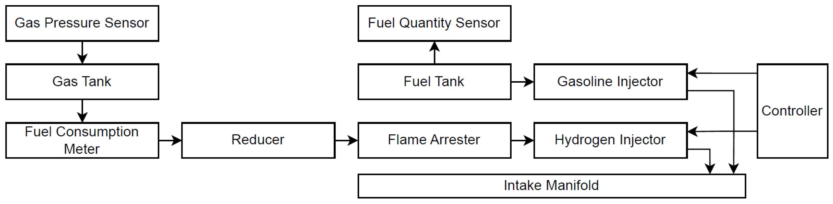
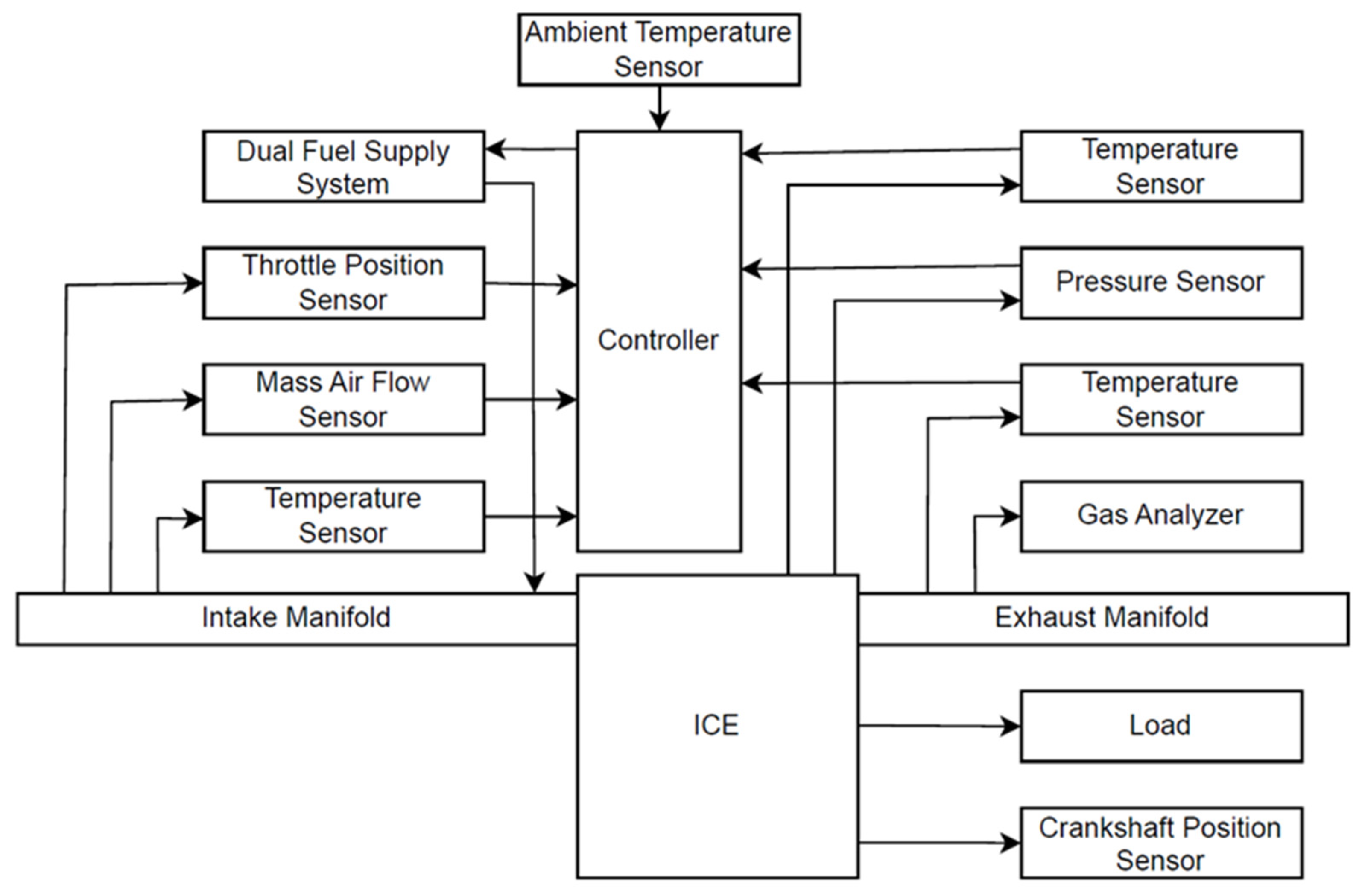
2. Materials and Methods

For the experiments, a NISSAN HR16DE (Nissan Motor Co., Ltd., Yokohama, Japan) engine was selected (Table 1). This engine is equipped with an indirect multi-port injection (MPI) system for gasoline, controlled by a MoTeC M800 (MoTeC, Melbourne, Australia) reprogrammable engine control unit (ECU). The MoTeC ECU provides extensive control over various engine parameters, including intake valve timing, ignition timing, trim, and timing of primary and secondary injectors.
To enable the operation of a dual-fuel supply system, secondary injectors were installed in the intake manifold for hydrogen injection. The MoTeC ECU was reprogrammed to control gasoline and hydrogen injection systems, allowing the precise regulation of fuel injection for each fuel type. In the high-pressure hydrogen supply line, an additional pressure regulator was installed to reduce the pressure to 5 bar before the injector rail. However, if a higher hydrogen ratio is required in the dual-fuel mixture, the pressure can be increased up to 200 bar. Although flame propagation is not possible in pure hydrogen, a flame arrestor was installed in the fuel supply line as a safety precaution to mitigate potential risks arising from hydrogen–air mixture formation due to diffusion or backflow near the injectors. A detailed block diagram of the dual-fuel system is shown in Figure 1.
The fuel properties listed in Table 2 for both gasoline and hydrogen came from density data reported in previous studies and from calculated mass fractions of the individual components. In this study, the reference fuel is gasoline blended with 10% bioethanol. Since hydrogen has a much lower volumetric energy density, a larger volume must be added during the intake stroke, which crowds the cylinder and lowers volumetric efficiency.
Gasoline E95 with 10% bioethanol (AB “ORLEN Lietuva”, Mažeikiai, Lithuania) and hydrogen (UAB “ELME MESSER LIT”, Vilnius, Lithuania) with a purity of 99.999 was used; fuel rations, ignition timing, marking examples, and properties are presented in Table 3. The hydrogen mass fraction was increased up to 30%, as knocking phenomena were observed at this concentration level. The hydrogen mass flow rates were measured using Coriolis-type RHEONIK RHM 015 (Rheonik Messtechnik GmbH, Odelzhausen, Germany) mass flowmeters, with a measurement range of 0.004–0.6 kg/min and an accuracy of ±0.10%. Gasoline consumption was measured on a scale-based mass flowmeter with an accuracy of ±0.10%.
A BOSCH LSU 4.9 (Robert Bosch Ltd., Abstatt, Germany) wideband oxygen sensor was added for real-time air–fuel ratio monitoring. To maintain a stable engine operating temperature throughout all experiments, a plate heat exchanger was added into the engine’s cooling system. Engine load was controlled using an AMX200/100 (Automex, Gdansk, Poland) engine dynamometer stand, with a brake torque (MB) measurement accuracy of ±0.9 Nm. Engine load was set for 0.235 MPa of brake mean effective pressure (BMEP), 0.472 MPa, and 0.708 MPa, while engine speed was set for 2000 rpm, 2500 rpm, and 3000 rpm.
The brake mean effective pressure [MPa] represents the work performed per unit of cylinder displacement ( V H ) and, for a four-stroke engine (τ = 4), is calculated using the following formula, taking into account the brake torque and the engine displacement volume [48]:
B M E P = M B · 30 · τ V H · 9549 .
The specific fuel consumption [g/kWh] for each fuel type is determined based on the hourly consumption of the respective fuel ( B f ) and the engine brake power ( P B ), using the following formula [48]:
B S F C = B f · 1000 P B .
The brake thermal efficiency of the engine operating on dual fuels is calculated by taking into account the engine brake power and the total energy input from all fuel types, using the following formula [48]:
B T E = P B · 3.6 ( B G · L H V G + B H 2 · L H V H 2 ) ,
The intake air mass flow was measured using a BOSCH HFM 5 (Robert Bosch Ltd., Abstatt, Germany) sensor, providing an accuracy of 2%. A block diagram of the engine test bench and measurement equipment is presented in Figure 2.
For data post-processing and setting the ignition timing at each measurement point, in-cylinder pressure was continuously monitored and logged. Ignition timing was adjusted for each measurement point, setting the maximum in-cylinder pressure at 12 CAD after TDC. Pressure measurements were performed using an AVL ZI31_Y7S (AVL DiTEST, Graz, Austria) sensor integrated into a modified spark plug (Table 4). The sensor signal was amplified by an AVL DiTEST DPM 800 (AVL DiTEST, Graz, Austria) signal amplifier and recorded using the LabVIEW 2025 Q1 Real-Time module (National Instruments Corp., Austin, TX, USA). For each experimental condition, pressure data from 100 consecutive combustion cycles were logged.
In order to evaluate engine operating stability, the coefficient of variation of the indicated mean effective pressure ( C O V I M E P ) was calculated using pressure data from 100 consecutive cycles, according to the formula [48]
C O V I M E P = σ I M E P I M E P ¯
where σ I M E P —the standard deviation of IMEP; and I M E P ¯ —the mean value over the specified number of cycles.
Exhaust gas temperature was measured directly in the exhaust manifold. To measure the exhaust gas emission, an additional pipe of smaller diameter was connected to the main exhaust before the catalytic converter. This configuration reduced the flow rate and temperature of the sampled exhaust gases. The exhaust gas composition was analyzed using an AVL DiCOM 4000 analyzer (AVL DiTEST, Graz, Austria), a gas analyzer capable of measuring NOx emission up to 5000 ppm and HC up to 20 000 ppm with an accuracy of 1 ppm; CO up to 10% by vol. and O2 up to 25% by vol. with an accuracy of 0.01%; and CO2 emission measures up to 20% by vol. with an accuracy of 0.1%.

3. Results

The experimental results are presented from several perspectives. First, in-cylinder pressure versus crank angle diagrams are provided to illustrate the influence of hydrogen supplementation on the combustion process in an SI engine. The experiments were conducted at a constant engine speed of 2500 rpm and a brake mean effective pressure (BMEP) of 0.472 MPa, using pure gasoline as well as gasoline–hydrogen mixtures containing 0%, 10%, 20%, and 30% hydrogen by mass. In the second stage, the engine’s energy performance indicators were evaluated under medium-speed operating conditions (2000 rpm, 2500 rpm, and 3000 rpm) and moderate loads (0.235 MPa, 0.472 MPa, and 0.708 MPa). The third stage presents pollutant emission data under the same range of engine speeds and loads, with varying hydrogen mass fractions in the fuel blend.

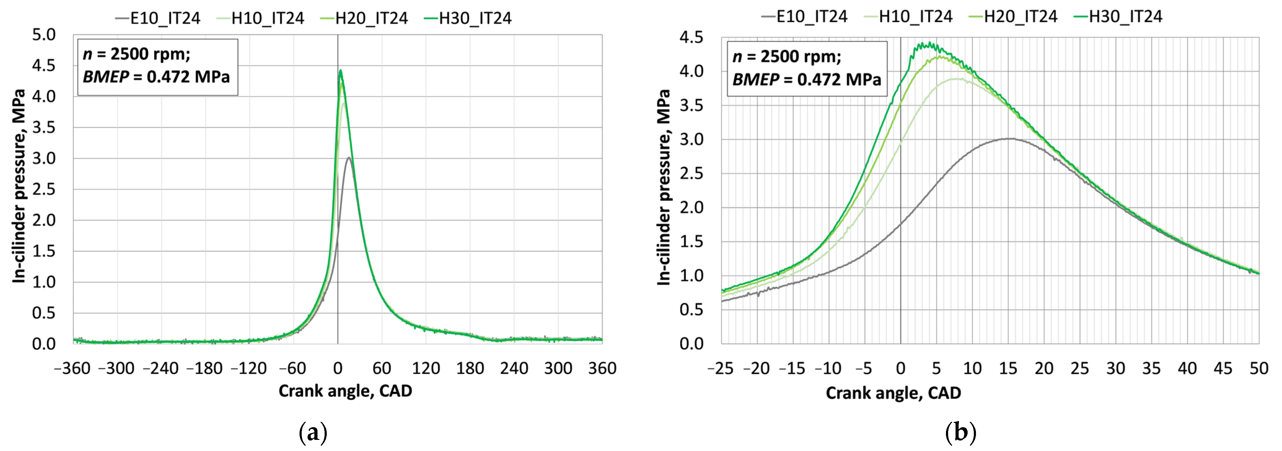
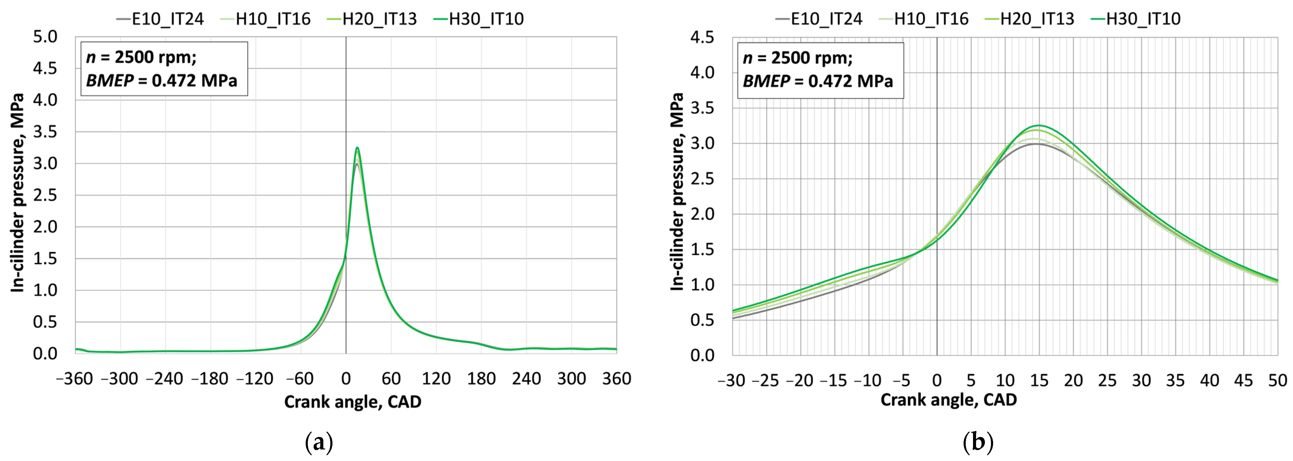
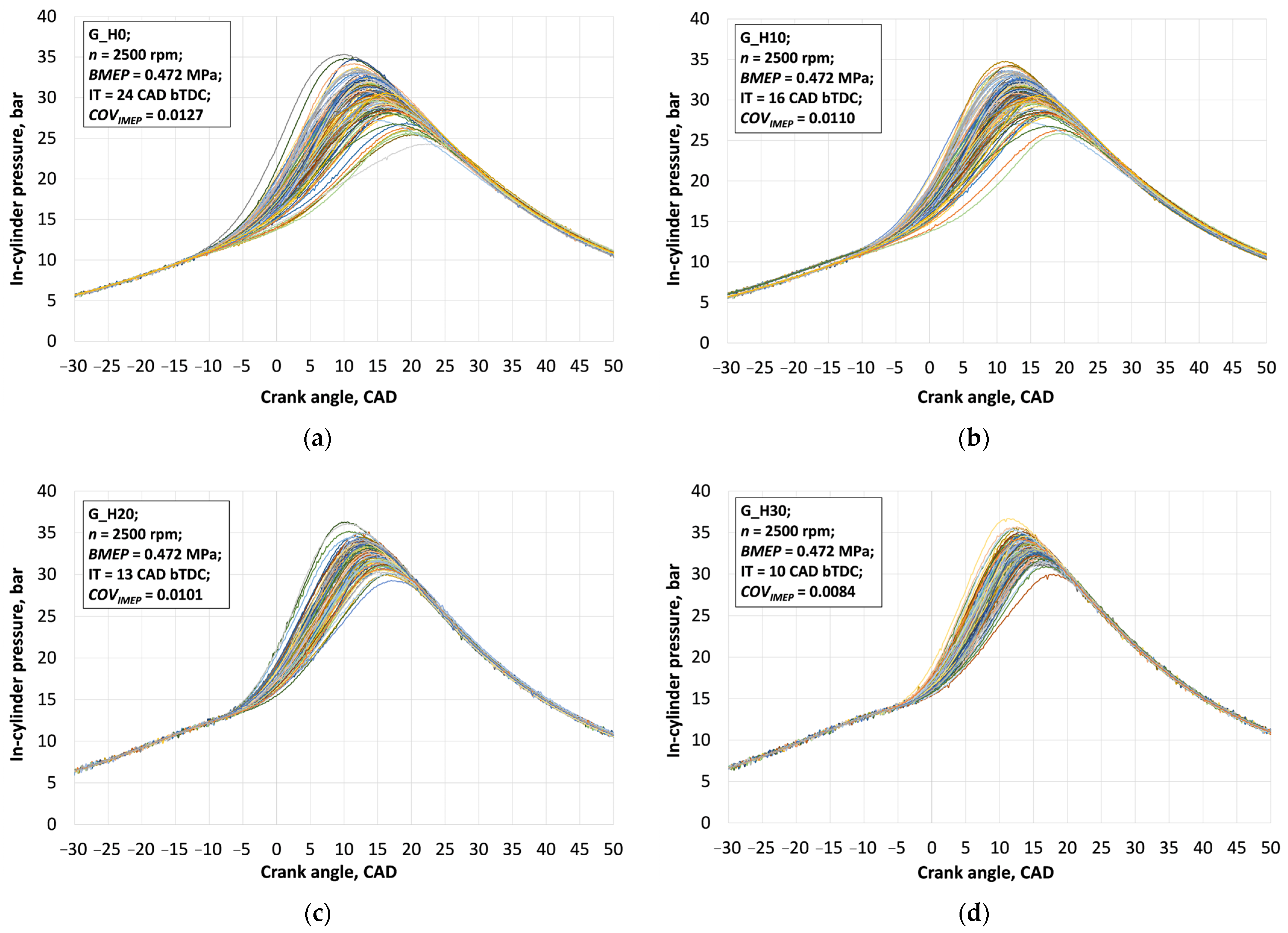
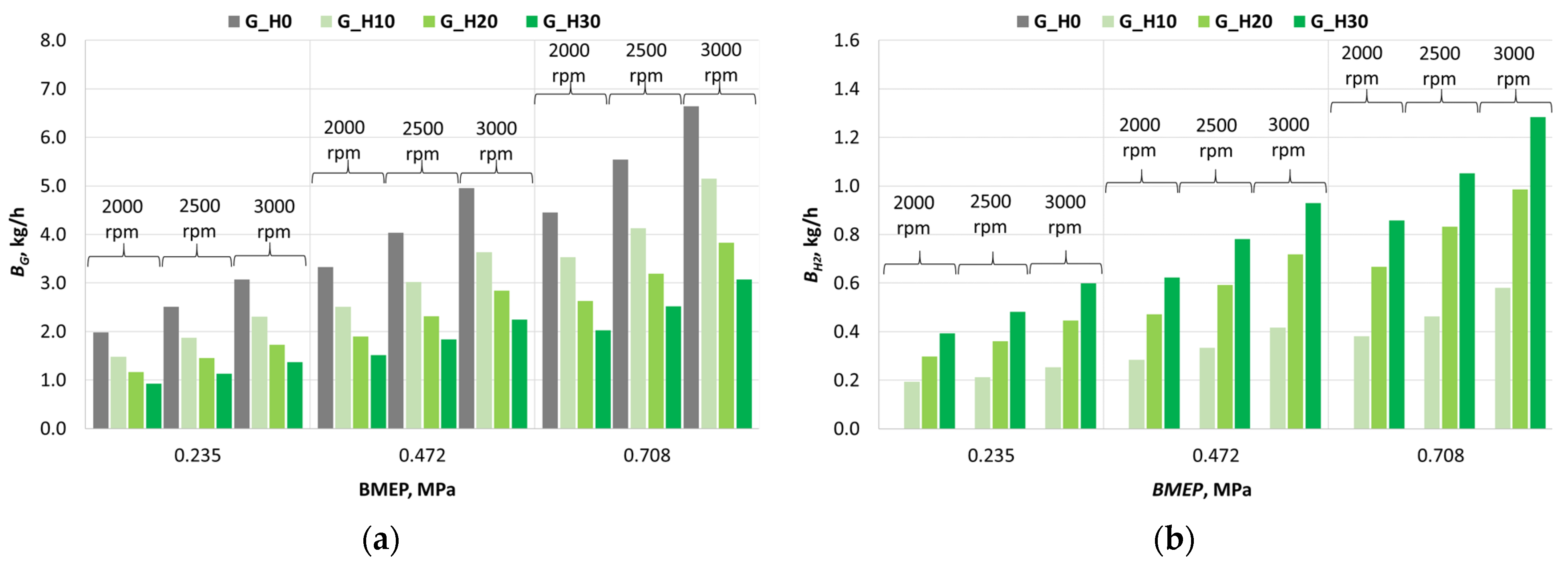
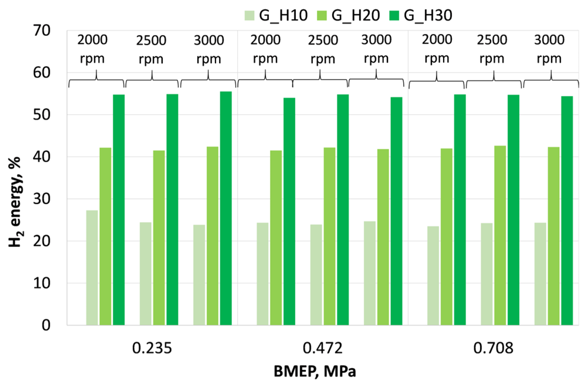
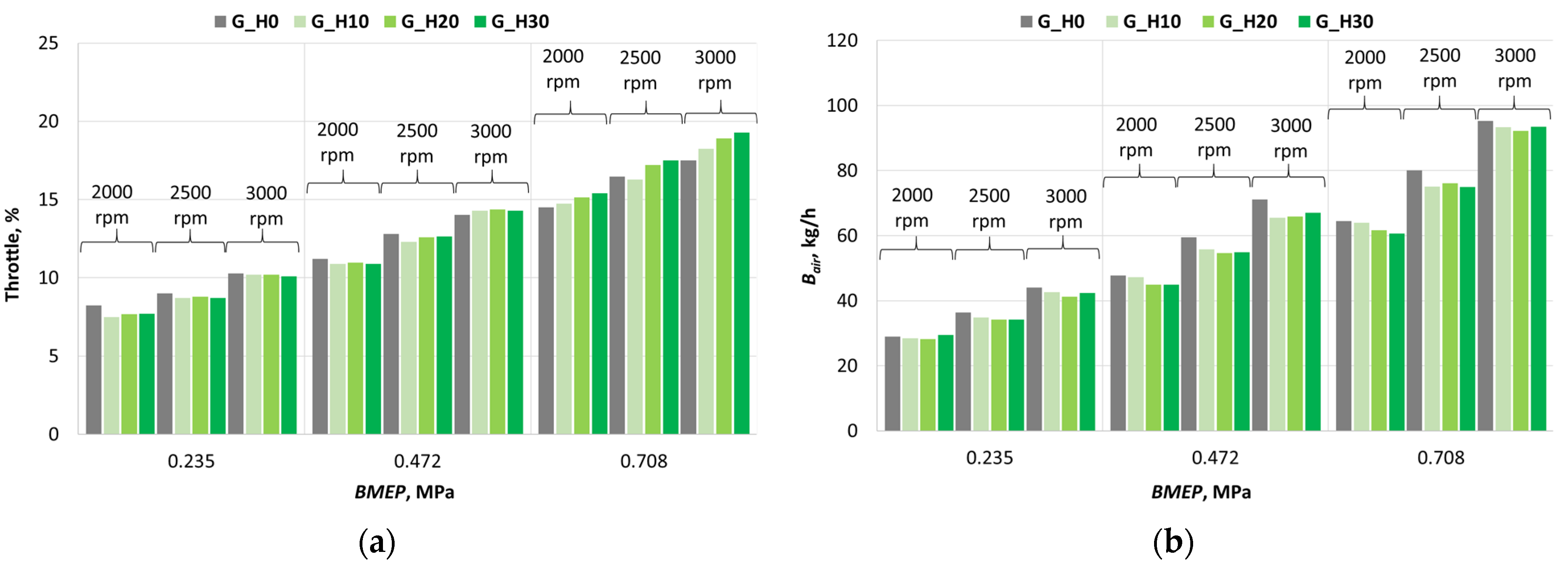
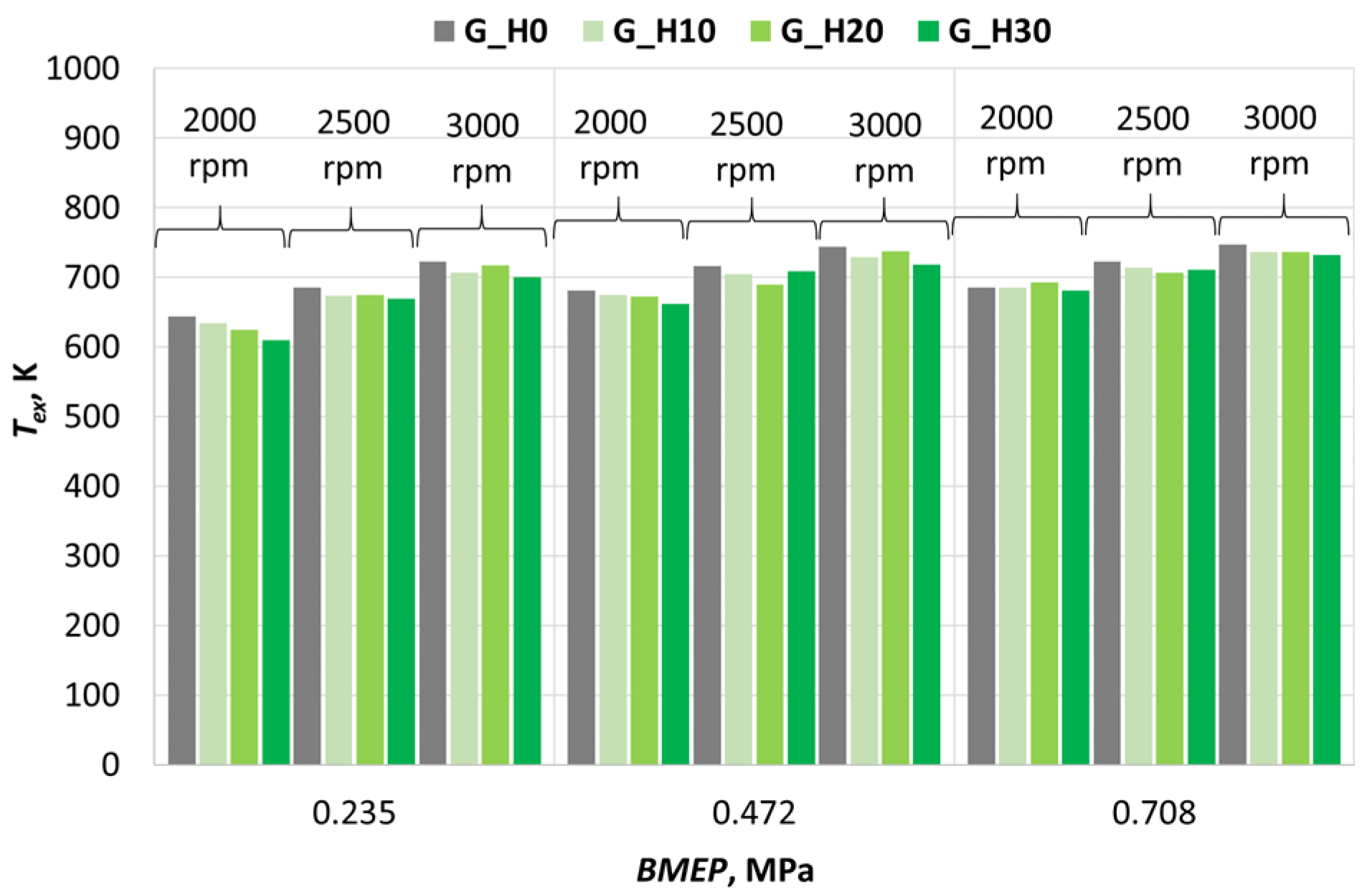
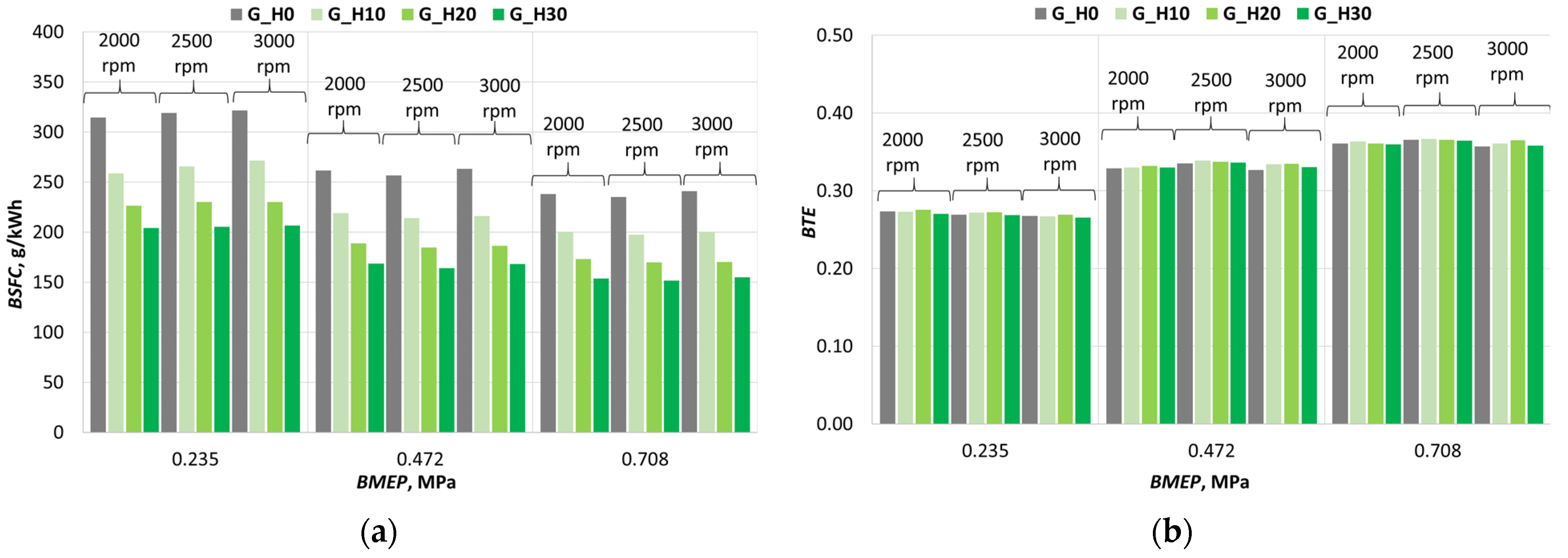
3.1. Investigation of Engine Combustion Behavior and Energy Performance Indicators

An analysis of the cylinder pressure traces at an engine speed of 2500 rpm and BMEP of 0.472 MPa, while maintaining the optimal ignition timing (IT) for gasoline at 24° crank angle degrees before top dead center (CAD bTDC), reveals that the peak in-cylinder pressure increases significantly with rising hydrogen content in the mixture (Figure 3a). This effect is attributed to the higher reactivity of hydrogen and its faster flame propagation rate compared to gasoline. Furthermore, the pressure peak occurs at increasingly earlier crank angles as the hydrogen concentration rises, indicating that the combustion process both starts and completes more rapidly. These phenomena are characteristic of hydrogen due to its short autoignition delay and high flame speed.
A supplementary diagram focusing on a narrower crank angle window (−25° to +50° CAD) further illustrates that the pressure rise becomes steeper with higher hydrogen content (Figure 3b), suggesting that energy is released over a shorter duration and that the combustion process becomes more intense. While this behavior can improve thermal efficiency, it also increases the mechanical loading on engine components and can promote knock phenomena, which were observed at 30% hydrogen by mass. The earlier and sharper pressure peaks indicate a heightened risk of knock, emphasizing the need for precise ignition timing control. It is also evident that even small changes in hydrogen concentration can substantially influence cylinder pressure if the ignition timing is not adjusted accordingly. In this test case, the peak cylinder pressure increased by approximately 46%, from 3.0 MPa (at 15° CAD aTDC) to 4.2 MPa (at 3° CAD aTDC).
Although the pressure traces do not directly provide emission data, the observed combustion characteristics suggest that hydrogen addition likely contributes to reduced CO and unburned HC emissions due to more complete combustion. However, the associated increase in combustion temperature may result in elevated NOx emissions, highlighting the need for further emission analysis.
In summary, hydrogen enrichment in gasoline-fueled SI engines enhances combustion intensity and efficiency but introduces challenges related to knock control and combustion stability. These findings are crucial for optimizing dual-fuel strategies aiming to balance efficiency, emission compliance, and engine durability.
To prevent knock phenomena initiated by hydrogen enrichment, a series of tests were conducted under similar conditions with delayed IT, ensuring that the peak cylinder pressure occurred at 14–15° CAD aTDC for both pure gasoline and gasoline–hydrogen mixtures. As shown in Figure 4a, with increasing hydrogen content, the ignition timing was systematically delayed—from 24° bTDC (without hydrogen) to 10° bTDC (with 30% hydrogen by mass). Despite this retardation, the pressure peak remained close to TDC, indicating that hydrogen enables fast and efficient combustion even at later ignition timings. This effect is attributed to hydrogen’s combustion properties, including short autoignition delay and high flame propagation speed.
Figure 4b, which presents the same experimental data, provides a clearer depiction of how the peak pressure magnitude and timing shift with varying hydrogen content and IT. It is evident that even with delayed ignition, higher hydrogen concentrations result in elevated peak pressures, indicating a more intense combustion process. This effect is particularly pronounced at a hydrogen concentration of 30%, where one of the highest pressure peaks is observed, despite the latest ignition timing among all tested conditions. In this case, the peak cylinder pressure increased by approximately 10%, from 3.0 MPa (15° CAD aTDC) to 3.2 MPa (15° CAD aTDC).
These results demonstrate that hydrogen supplementation allows effective control of the combustion process through ignition timing adjustment. By retarding the ignition, premature combustion and knock can be avoided while maintaining high combustion efficiency. This is especially important when balancing engine performance with reliability and emission standards. However, it must be noted that the more intense combustion and higher peak pressures may increase mechanical loads on engine components, necessitating careful optimization of both IT and fuel mixture composition.
In summary, hydrogen enrichment in gasoline-fueled SI engines, when combined with appropriate IT control, enables efficient and well-managed combustion. These findings are of particular relevance for advancing dual-fuel strategies and developing next-generation combustion control systems aimed at simultaneously improving efficiency and reducing emissions.
An analysis of all four in-cylinder pressure variation diagrams (Figure 5) reveals a clear trend regarding the effect of increasing hydrogen concentration in the fuel mixture (from 0% to 30%) on pressure dynamics, combustion intensity, and process stability. In all graphs, the engine speed (2500 rpm) and brake mean effective pressure (BMEP = 0.472 MPa) are kept constant, allowing for an objective evaluation of hydrogen’s influence. In each case, the coefficient of variation of indicated mean effective pressure (COVIMEP) was calculated based on 100 consecutive engine cycles.
When operating with pure gasoline (G_H0), the ignition timing is the earliest—24 CAD bTDC—and the COVIMEP value reaches 0.0127 (Figure 5a). This indicates lower combustion stability in the absence of hydrogen, despite the pressure peak occurring shortly aTDC. In the second graph, representing 10% hydrogen enrichment (G_H10), the ignition timing is retarded to 16 CAD bTDC, and the COVIMEP decreases to 0.0110 (Figure 5b). This demonstrates that even a 10% hydrogen addition improves combustion uniformity, with more consistent pressure curves between cycles, despite later ignition. In the G_H20 case, ignition is further delayed to 13 CAD bTDC, and COVIMEP drops to 0.0101 (Figure 5c), indicating further enhancement in combustion stability. The pressure peak is achieved similarly to previous cases and is effectively utilized during the power stroke. For the G_H30 case, with 30% hydrogen concentration, the ignition timing is 10 CAD bTDC, and COVIMEP decreases to 0.0084 (Figure 5d), representing a 34% reduction compared to G_H0. This reflects the highest level of combustion stability and efficiency, with pressure traces exhibiting minimal variation and peak pressure occurring at an optimal crank angle.
In summary, increasing hydrogen content in the fuel enables the use of later ignition timing while maintaining or even improving combustion efficiency. Simultaneously, a reduction in COVIMEP values indicates more stable engine operation. These findings confirm that hydrogen enrichment is an effective strategy for enhancing both the stability and efficiency of internal combustion engine performance.
Figure 6a,b present the individual consumption of gasoline and hydrogen at different engine loads and speeds. In the diagram showing the hourly gasoline consumption (BG), a general increase in fuel consumption is observed with rising BMEP and engine speed (Figure 6a), which corresponds to higher power output. However, at each BMEP level, the BG values decrease as the hydrogen concentration in the fuel mixture increases, particularly at higher engine speeds. This indicates that hydrogen supplementation enables the engine to produce the same power while consuming significantly less gasoline. Hydrogen consumption increases proportionally with engine load, speed, and the H2 mass fraction in the mixture (Figure 6b).
Taking into account the mass-based fuel consumption of gasoline and hydrogen, as well as their respective lower heating values (LHVs), the H2 energy share in the total fuel mixture was calculated. The LHV of gasoline (composed of 90% pure gasoline and 10% bioethanol) is 41.88 MJ/kg, while that of pure hydrogen is 120 MJ/kg. The results of the experiments and calculations show that in the G_H10 case, the fuel mixture LHV was 49.69 MJ/kg, and the H2 energy share accounted for approximately 24.2% of the total fuel energy (at n = 2000 rpm and BMEP = 0.235 MPa, the H2 energy share was slightly higher due to the minimum flow measurement limitations of the Coriolis-type H2 fuel flowmeter). In the G_H20 case, the mixture LHV increased to 57.50 MJ/kg, with hydrogen contributing about 41.7% of the total energy. For G_H30, the LHV of the fuel mixture increased to 65.31 MJ/kg, with hydrogen providing approximately 55.1% of the total fuel energy (Figure 7). These results highlight hydrogen’s potential as a flexible and adaptable energy carrier for ICE. It can be effectively utilized across a wide range of engine speeds and loads while maintaining a substantial share in the overall energy balance.
Throttle position and intake air mass (Bair) were analyzed to determine how these parameters are affected by varying hydrogen mass fractions under different engine operating conditions. With H2 supplementation, throttle opening decreased by up to 8%, particularly at low load (BMEP = 0.235 MPa) and low speed (n = 2000 rpm) when the hydrogen mass fraction reached 10% (Figure 8a). As the hydrogen concentration increased to 30%, and engine load and speed did not exceed BMEP = 0.472 MPa and n = 3000 rpm, respectively, the throttle opening remained lower or similar compared to operation with pure gasoline (G_H0). This suggests that in the low to medium load and speed range, engine power output can be maintained using up to 30% H2 enrichment without increasing the throttle position. However, at higher loads (BMEP = 0.708 MPa), increasing the hydrogen concentration to 10%, 20%, and 30% required the throttle to be opened approximately 4%, 8%, and 10% more, respectively. This indicates that under high load conditions, if the throttle position is fixed, an increase in hydrogen concentration will lead to a decrease in BMEP.
Across the entire tested range of engine loads and speeds, the Bair decreases with increasing H2 concentration (Figure 8b), despite varying throttle responses. At low load, throttle opening decreases with higher H2 content, while at medium and high loads, the throttle opening increases with increasing hydrogen concentration. When the H2 mass fraction is raised to 30%, Bair decreases by up to 6%. This reduction is attributed to the increase in the fuel mixture’s LHV, which rises by approximately 43.5%—equivalent to around 43.4% lower fuel mass consumption. Additionally, the amount of air required to combust 1 kg of the fuel mixture increases by approximately 36%. These effects are further influenced by hydrogen’s extremely low density—approximately 14.3 times lower than that of air under standard conditions—resulting in a significantly larger volumetric displacement, as well as by residual gases and their temperature inside the cylinder. This comprehensive analysis explains the observed trends in throttle position and cylinder air-filling behavior as H2 concentration increases under various engine load conditions.
The exhaust gas temperature (Tex) is directly related to the engine operating mode and the combustion process. As engine load increases, Tex rises due to the higher energy content of the fuel–air mixture entering the cylinder (Figure 9). Tex also increases with engine speed, as the exhaust valve opens earlier relative to the start of combustion. When the hydrogen concentration is increased up to 30%, a reduction in Tex of up to 5% is observed compared to the G_H0 case, indicating that less energy is carried away with the exhaust gases. This reduction trend is more pronounced at low engine loads and speeds. It can be anticipated that such a decrease in Tex may contribute to improved engine thermal efficiency. However, it is also likely that the more intense heat release associated with hydrogen combustion leads to higher in-cylinder temperatures and a greater proportion of energy being transferred to the engine’s cooling system, which could partially offset the gains in efficiency. In evaluating Tex, it is also important to note that lower exhaust temperatures have a positive effect on the durability of exhaust valves and their seats.
Across the entire tested range of engine loads and speeds, a significant reduction in brake specific fuel consumption (BSFC) was observed—approximately 18.1%, 32.8%, and 43.4%—as the H2 concentration in the fuel was increased to 10%, 20%, and 30%, respectively (Figure 10a). This improvement is attributed to the corresponding increases in the LHV of the fuel mixture by 17.1%, 31.4%, and 43.5%, as well as changes in thermal efficiency. The relative change in BSFC remained consistent across different engine operating conditions at a given H2 concentration, as the IT was adjusted in all cases to ensure that the maximum in-cylinder pressure occurred at 14–15 CAD aTDC. This approach maintained similar conditions for converting peak pressure into effective work, allowing for a valid comparison of BSFC across various regimes.
Based on fuel consumption data and the respective LHV, brake thermal efficiency (BTE) was calculated across the entire range of operating conditions (Figure 10b). The highest BTE values were achieved at the maximum tested load (BMEP = 0.708 MPa), where the engine’s mechanical efficiency increases. However, due to IT adjustments, changes in BTE with varying H2 concentrations remained relatively small. A 2–3% increase in BTE was observed under medium engine loads with 10–20% hydrogen in the fuel mixture, primarily due to the faster combustion speed of the gasoline–hydrogen blend, which enables more effective utilization of the fuel’s energy. The rise in BTE partially correlates with the observed decrease in Tex as H2 concentration increases. However, at lower loads, a greater portion of the released heat is transferred through the combustion chamber and cylinder walls to the cooling system, which reduces Tex without a corresponding increase in BTE.

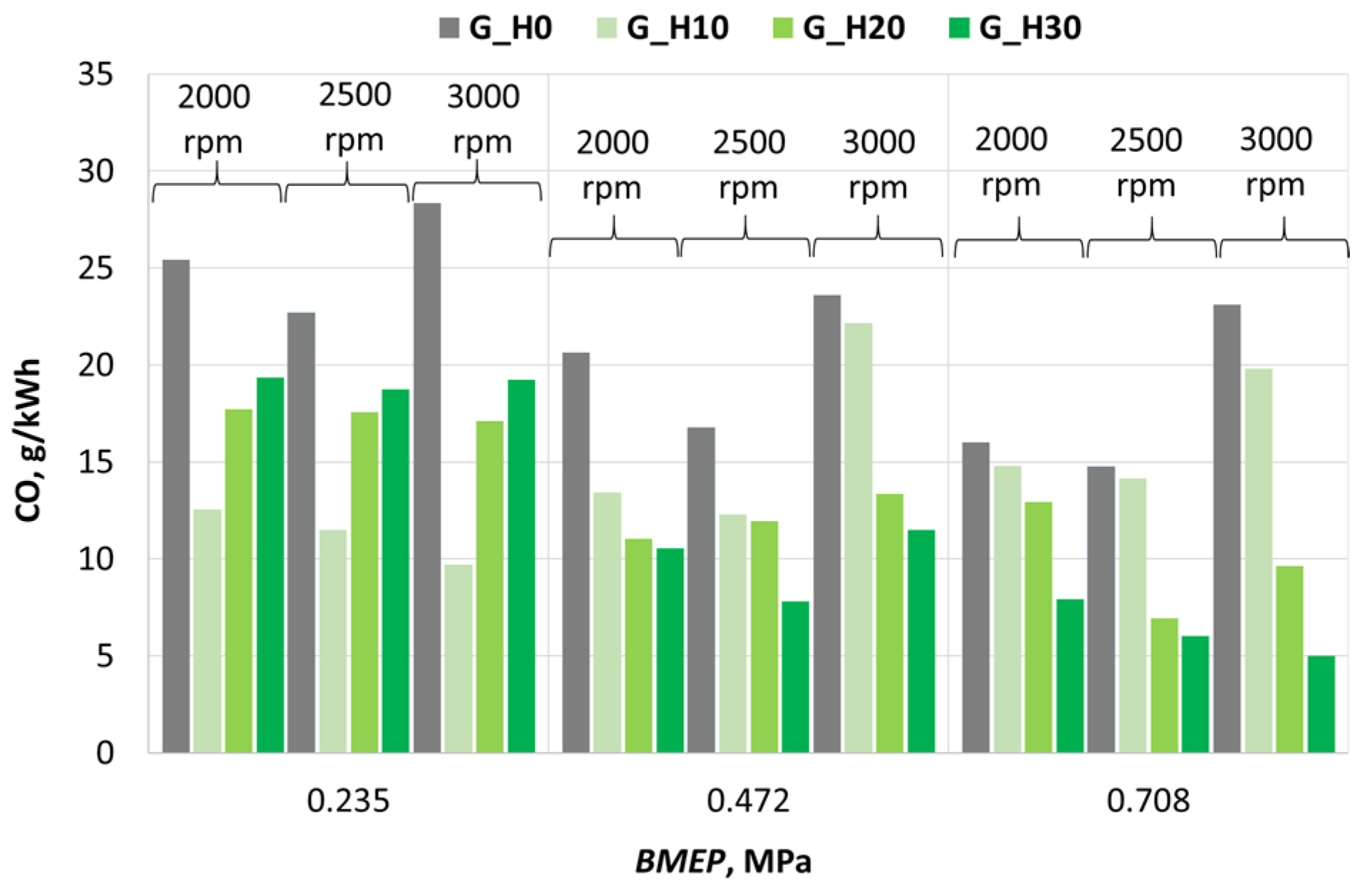
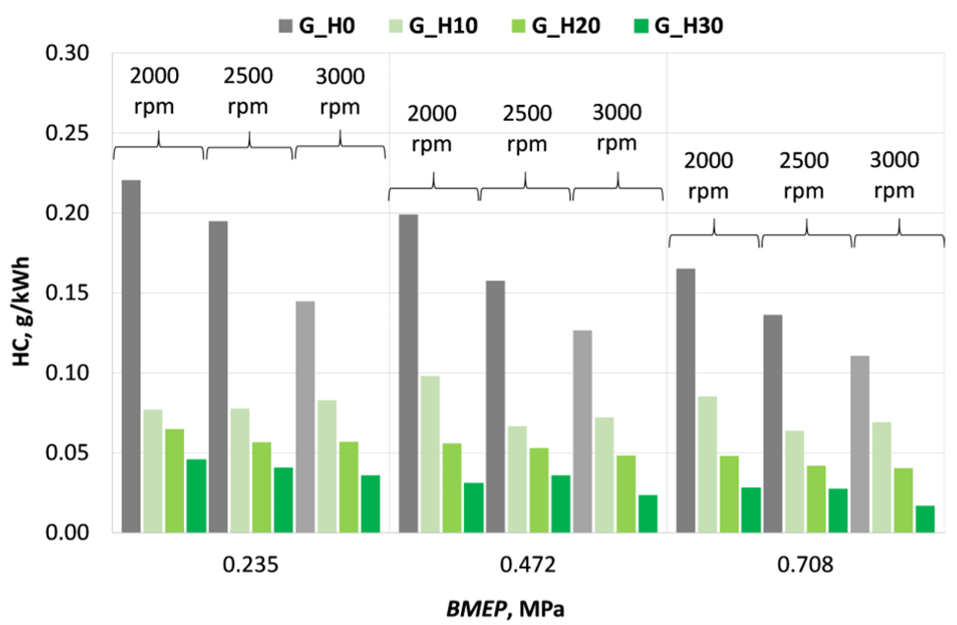
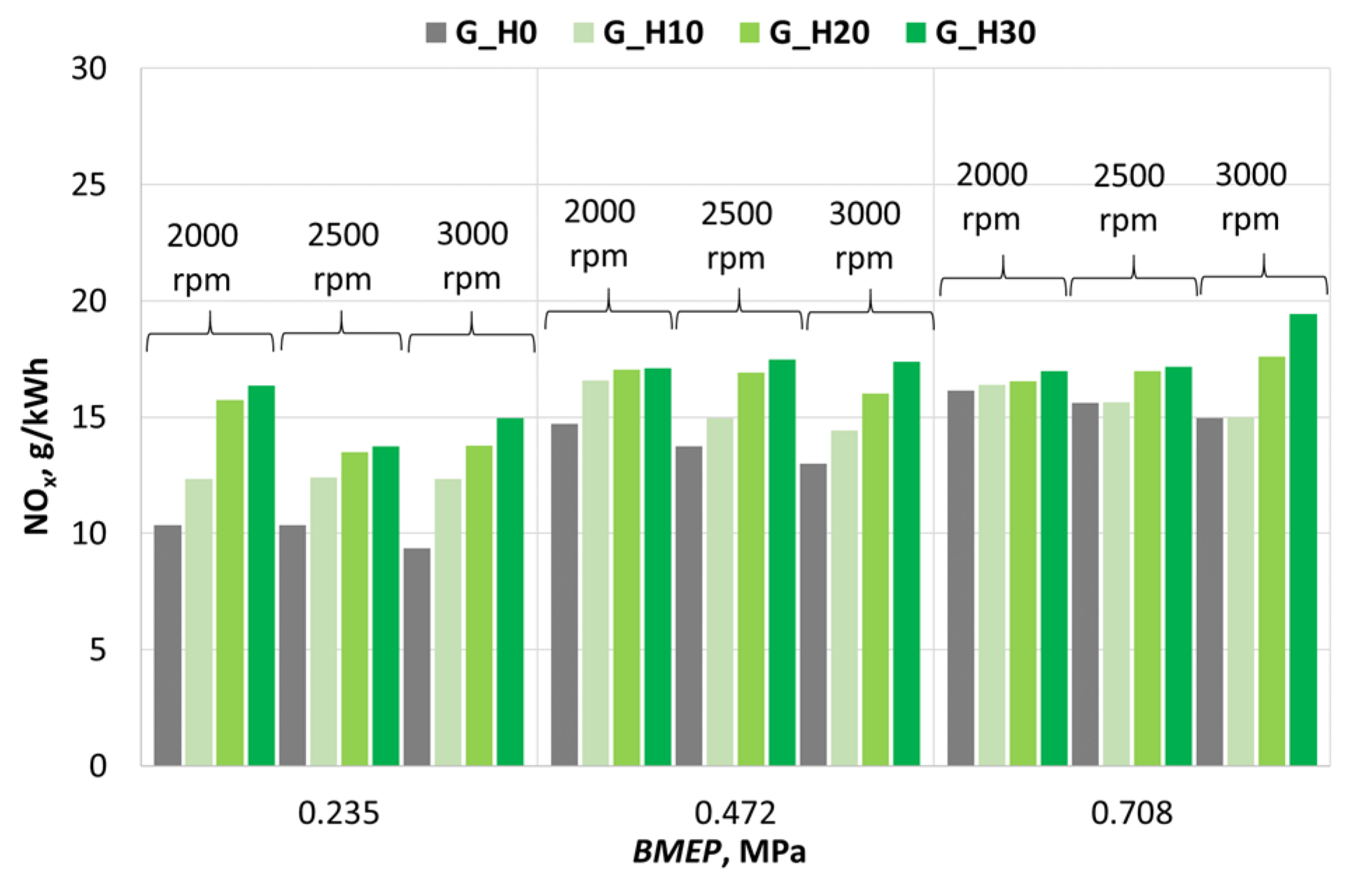
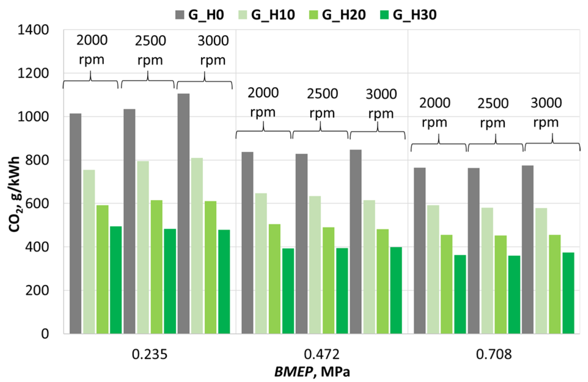
3.2. Investigation of Engine Environmental Performance Indicators

As the hydrogen mass fraction in the gasoline blend increases, the specific emission of CO—a byproduct of incomplete combustion—varies depending on the engine operating conditions (Figure 11). When the hydrogen concentration is gradually increased to 10%, 20%, and 30% under low load conditions (BMEP = 0.235 MPa) and at 3000 rpm, the reduction in CO emissions compared to G_H0 becomes progressively smaller, at approximately ~66%, ~40%, and ~32%, respectively. However, under medium load conditions (BMEP = 0.708 MPa) and the same engine speed (3000 rpm), the trend reverses, with CO emissions decreasing more significantly—by approximately ~14%, ~58%, and ~78%, respectively. The increase in specific CO emissions as the hydrogen concentration rises from 10% to 30% under low load conditions (BMEP = 0.235 MPa) is likely caused by uneven mixture formation and oxygen deficiency, as hydrogen occupies volume that would otherwise be filled by air. A comprehensive evaluation of the entire range of tested loads and engine speeds revealed that increasing the hydrogen mass fraction in the fuel to 10%, 20%, and 30% leads to a reduction in specific CO emissions by approximately 29%, 38%, and 46%, respectively. This reduction is attributed to the fact that hydrogen is a carbon-free fuel and, therefore, does not produce either CO or CO2 during combustion. Moreover, the elevated combustion temperature associated with hydrogen addition further reduces CO formation during the combustion of gasoline. Increasing the H2 fraction in the fuel mixture accelerates the oxidation of carbon monoxide through chain-branching reactions involving OH and H radicals, thereby further reducing CO emissions.
It is observed that as the H2 concentration in the fuel increases, the specific emission of unburned HC significantly decreases across all examined engine operating conditions (Figure 12). This indicates that hydrogen enrichment enhances the combustion process, as hydrogen has a high flame speed and improved mixture ignitability. These properties contribute to a reduction in unburned fuel and also lead to an increase in combustion temperature, which, in turn, accelerates the breakdown of unburned HC. Moreover, pure hydrogen contains no hydrocarbon compounds, which further contributes to the reduction of HC emissions.
Across the full range of tested engine conditions, increasing the H2 mass fraction from 0% to 10%, 20%, and 30% led to reductions in HC specific emissions of approximately 51%, 67%, and 80%, respectively, compared to G_H0. When evaluating the ratio between the reduction in HC emissions and the corresponding increase in H2 mass supply, the most favorable effect was observed when increasing H2 content from 0% to 10% under low-load and low-speed conditions. The greatest reduction in HC emissions was achieved under low-load operation, where combustion conditions are generally less favorable and result in higher HC emissions when the engine is fueled with gasoline alone.
When the engine operates on pure gasoline (G_H0), the specific emission of NOx increases with rising engine load from BMEP = 0.235 MPa to BMEP = 0.708 MPa due to a significant increase in fuel mass entering the cylinders and the resulting rise in combustion temperature (Figure 13). Under constant load conditions with increasing engine speed, NOx emissions from gasoline combustion tend to decrease, as the cylinder volume expands more rapidly during the power stroke, resulting in a lower temperature rise at the beginning of the expansion process.
However, under the same load conditions, when hydrogen is added to the fuel mixture, NOx emissions increase with rising engine speed, especially at higher loads. This is attributed to hydrogen’s faster heat release per CAD and the higher peak temperatures, which promote the formation of thermal NOx.
Across all investigated engine operating regimes, calculations showed that replacing G_H0 with G_H10, G_H20, and G_H30 led to increases in NOx-specific emissions of approximately 12%, 24%, and 31%, respectively. While enriching gasoline with H2 effectively reduces CO and HC emissions, it also leads to increased NOx emissions due to the higher combustion temperatures. Hydrogen also accelerates the overall combustion process and affects the chemical environment in the cylinder. Faster reaction kinetics, higher in-cylinder pressures, and reduced concentrations of diluents such as CO2 all contribute to intensified thermal NOx formation. Therefore, to achieve an optimal emissions balance, H2 content should be carefully calibrated in combination with other emission control strategies, such as advanced ignition timing management and exhaust gas recirculation (EGR) control.
When the engine operates on G_H0 fuel, the specific emission of CO2—a greenhouse gas—decreases with increasing load due to the reduction in BSFC. This trend persists as the mass fraction of carbon-free H2 in the fuel mixture increases (Figure 14), although the reduction in CO2 emissions is not directly proportional to the increase in hydrogen concentration.
Across all investigated engine operating conditions, it was found that when the hydrogen mass fraction reaches 10%, 20%, and 30%, CO2 emissions decrease by approximately 25%, 42%, and 53%, respectively, compared to emissions from G_H0 fuel (Figure 7).
The conducted research confirms that CO2 emissions from the engine can be significantly reduced by employing a dual-fuel system and supplying additional hydrogen into the intake manifold of a gasoline-powered engine. This approach is an effective measure for reducing the climate impact of the transport sector and meeting increasingly strict environmental regulations. However, a critical prerequisite is that the hydrogen used must be produced from renewable resources that do not generate significant CO2 emissions.

4. Conclusions

The results of experimental investigations and numerical analysis reveal a significant influence of hydrogen enrichment on the combustion process, efficiency, stability, and emissions of an SI engine. The key findings are summarized as follows:
1. Increasing the H2 concentration in the fuel (from 0% to 30% by mass, or up to 55% by energy content) significantly intensifies the combustion process due to shorter autoignition delay and higher flame propagation speed. To prevent knock at higher H2 concentrations, IT was retarded to ensure that the peak in-cylinder pressure occurred at 14–15° CAD aTDC. Under these conditions, the engine’s BTE showed an improving trend, and combustion stability increased with hydrogen content, as evidenced by a reduction in COVIMEP to 0.0084—approximately 34% lower than in the G_H0 case.
2. Lower throttle openings observed at low loads with H2 addition indicate that engine torque can be maintained without increasing throttle position. However, under medium load conditions, greater throttle openings are required compared to gasoline operation, despite a reduction in intake air mass due to hydrogen occupying a larger portion of the cylinder volume.
3. Faster combustion of H2 led to a decrease in Tex by up to 5%, suggesting lower heat losses through the exhaust system. However, the increase in BTE was limited to 2–3%, as a larger fraction of heat was transferred through the combustion chamber surfaces. In the G_H30 case, due to a ~43.5% increase in the LHV, BSFC was reduced by ~43.4%.
4. As the H2 mass fraction in the fuel was increased from 0% to 10%, 20%, and 30%, specific emissions of CO decreased by ~29%, ~38%, and ~46%, and HC emissions by ~51%, ~67%, and ~80%, respectively. These reductions are attributed to the lower carbon-to-hydrogen (C/H) ratio in the fuel mixture and more complete combustion enabled by H2. However, NOx emissions increased by ~12%, ~24%, and ~31% due to higher combustion temperatures. CO2 emissions decreased by ~25%, ~42%, and ~53%, closely matching the H2 energy share in the fuel, due to reduced carbon content.
5. The use of hydrogen as a supplementary fuel component in SI engines shows strong potential for improving engine efficiency and stability while reducing emissions of CO, HC, and CO2. However, precise IT control and monitoring knock tendencies and NOx formation are essential. The results confirm that the dual-fuel concept utilizing hydrogen can be successfully applied in the development of high-efficiency, low-emission engine technologies.

Author Contributions

Conceptualization, S.P., A.R., and D.K.; methodology, A.R., T.V., and S.S.; software, A.U. and T.V.; validation, A.R., T.V., and D.K.; formal analysis, S.P., G.M., and A.U.; investigation, A.R., T.V., S.S., D.K., G.M., and A.U.; resources, S.P., G.M., and A.U.; data curation, A.R., S.S., D.K., and G.M.; writing—original draft preparation, S.P., A.R., D.K., and G.M.; writing—review and editing, T.V., S.S., and A.U.; visualization, A.R., D.K., and A.U.; supervision, S.P. and A.R.; project administration, S.P.; funding acquisition, S.P. All authors have read and agreed to the published version of the manuscript.

Funding

Research was conducted as part of the execution of Project “Mission-driven Implementation of Science and Innovation Programmes” (No. 02-002-P-0001), funded by the Economic Revitalization and Resilience Enhancement Plan “New Generation Lithuania”.

Data Availability Statement

The data presented in this study are available on request from the corresponding author.

Conflicts of Interest

The authors declare no conflicts of interest.

Abbreviations

The following abbreviations are used in this manuscript:
A/FAir/fuel mass ratio
aTDCAfter top dead center
BairIntake air mass
BfHourly fuel consumption
BGHourly gasoline consumption
BH2Hourly hydrogen consumption
BMEPBrake mean effective pressure
BSFCBrake specific fuel consumption
BTEBrake thermal efficiency
bTDCBefore top dead center
CADCrank angle degrees
CICompression-ignition
COVIMEPCoefficient of variation of indicated mean effective pressure
ECUEngine control unit
EGRExhaust gas recirculation
FCEVFuel cell electric vehicle
H2Hydrogen
ICEInternal combustion engine
ITIgnition timing
LHVLower heating value
MPIMulti-port injection
SISpark-ignition
TexExhaust gas temperature
TDCTop dead center

References

  1. Singh, M.; Singla, M.K.; Beryozkina, S.; Gupta, J.; Safaraliev, M. Hydrogen Vehicles and Hydrogen as a Fuel for Vehicles: A-State-of-the-Art Review. Int. J. Hydrogen Energy 2024, 64, 1001–1010. [Google Scholar] [CrossRef]
  2. Fakhreddine, O.; Gharbia, Y.; Derakhshandeh, J.F.; Amer, A.M. Challenges and Solutions of Hydrogen Fuel Cells in Transportation Systems: A Review and Prospects. World Electr. Veh. J. 2023, 14, 156. [Google Scholar] [CrossRef]
  3. Cybulsky, A.; Allroggen, F.; Shao-Horn, Y.; Mallapragada, D.S. Decarbonization of Aviation via Hydrogen Propulsion: Technology Performance Targets and Energy System Impacts. arXiv 2023, arXiv:2309.14629. [Google Scholar]
  4. Pardhi, S.; Chakraborty, S.; Tran, D.-D.; El Baghdadi, M.; Wilkins, S.; Hegazy, O. A Review of Fuel Cell Powertrains for Long-Haul Heavy-Duty Vehicles: Technology, Hydrogen, Energy and Thermal Management Solutions. Energies 2022, 15, 9557. [Google Scholar] [CrossRef]
  5. Cheekatamarla, P. Hydrogen and the Global Energy Transition—Path to Sustainability and Adoption across All Economic Sectors. Energies 2024, 17, 807. [Google Scholar] [CrossRef]
  6. Ihsan Shahid, M.; Rao, A.; Farhan, M.; Liu, Y.; Ahmad Salam, H.; Chen, T.; Ma, F. Hydrogen Production Techniques and Use of Hydrogen in Internal Combustion Engine: A Comprehensive Review. Fuel 2024, 378, 132769. [Google Scholar] [CrossRef]
  7. Goyal, H.; Jones, P.; Bajwa, A.; Parsons, D.; Akehurst, S.; Davy, M.H.; Leach, F.C.; Esposito, S. Design Trends and Challenges in Hydrogen Direct Injection (H2DI) Internal Combustion Engines—A Review. Int. J. Hydrogen Energy 2024, 86, 1179–1194. [Google Scholar] [CrossRef]
  8. Turner, J.W.G. Future Technological Directions for Hydrogen Internal Combustion Engines in Transport Applications. Appl. Energy Combust. Sci. 2025, 21, 100302. [Google Scholar] [CrossRef]
  9. Kourougianni, F.; Arsalis, A.; Olympios, A.V.; Yiasoumas, G.; Konstantinou, C.; Papanastasiou, P.; Georghiou, G.E. A Comprehensive Review of Green Hydrogen Energy Systems. Renew. Energy 2024, 231, 120911. [Google Scholar] [CrossRef]
  10. Kharel, S.; Shabani, B. Hydrogen as a Long-Term Large-Scale Energy Storage Solution to Support Renewables. Energies 2018, 11, 2825. [Google Scholar] [CrossRef]
  11. Pizzuti, I.; Conti, M.; Delibra, G.; Corsini, A.; Castorrini, A. Energy Storage and Management of Offshore Wind-Based Green Hydrogen Production. Processes 2025, 13, 643. [Google Scholar] [CrossRef]
  12. Serrano-Arévalo, T.I.; Tovar-Facio, J.; Ponce-Ortega, J.M. Optimal Incorporation of Intermittent Renewable Energy Storage Units and Green Hydrogen Production in the Electrical Sector. Energies 2023, 16, 2609. [Google Scholar] [CrossRef]
  13. Anastasiadis, A.G.; Papadimitriou, P.; Vlachou, P.; Vokas, G.A. Management of Hybrid Wind and Photovoltaic System Electrolyzer for Green Hydrogen Production and Storage in the Presence of a Small Fleet of Hydrogen Vehicles—An Economic Assessment. Energies 2023, 16, 7990. [Google Scholar] [CrossRef]
  14. Zun, M.T.; McLellan, B.C. Cost Projection of Global Green Hydrogen Production Scenarios. Hydrogen 2023, 4, 932–960. [Google Scholar] [CrossRef]
  15. Mekonnin, A.S.; Wacławiak, K.; Humayun, M.; Zhang, S.; Ullah, H. Hydrogen Storage Technology, and Its Challenges: A Review. Catalysts 2025, 15, 260. [Google Scholar] [CrossRef]
  16. Hossain Bhuiyan, M.M.; Siddique, Z. Hydrogen as an Alternative Fuel: A Comprehensive Review of Challenges and Opportunities in Production, Storage, and Transportation. Int. J. Hydrogen Energy 2025, 102, 1026–1044. [Google Scholar] [CrossRef]
  17. Maka, A.O.M.; Mehmood, M.; Chaudhary, T.N. Green Hydrogen Revolution and Its Pathway towards Sustainable Development. Clean Energy 2025, 9, 124–131. [Google Scholar] [CrossRef]
  18. Satyapal, S. U.S. DOE Hydrogen Program and National Clean Hydrogen Strategy. Available online: https://www.energy.gov/sites/default/files/2024-02/doe-h2-program-national-strategy-remarks-jan2024.pdf?utm_source=chatgpt.com (accessed on 1 May 2025).
  19. Department of Energy Announces $10.5 Million to Advance Hydrogen Combustion Engine Innovation. Available online: https://www.energy.gov/eere/fuelcells/articles/department-energy-announces-105-million-advance-hydrogen-combustion-engine (accessed on 1 May 2025).
  20. U.S. National Hydrogen Strategy and Roadmap|Hydrogen Program. Available online: https://www.hydrogen.energy.gov/library/roadmaps-vision/clean-hydrogen-strategy-roadmap?utm_source=chatgpt.com (accessed on 1 May 2025).
  21. Talus, K.; Martin, M. A Guide to Hydrogen Legislation in the USA: A Renewed Effort. J. World Energy Law Bus. 2022, 15, 449–461. [Google Scholar] [CrossRef]
  22. EU Hydrogen Strategy under the EU Green Deal|European Hydrogen Observatory. Available online: https://observatory.clean-hydrogen.europa.eu/eu-policy/eu-hydrogen-strategy-under-eu-green-deal (accessed on 1 May 2025).
  23. Communication from the Commission to the European Parliament, The Council, The European Economic and Social Committee and the Committee of the Regions. A Hydrogen Strategy for a Climate-Neutral Europe. 2020. Available online: https://energy.ec.europa.eu/system/files/2020-07/hydrogen_strategy_0.pdf (accessed on 5 May 2025).
  24. Optimisation of Hydrogen Powered Internal Combustion Engines (HYICE)|FP6. Available online: https://cordis.europa.eu/project/id/506604/reporting (accessed on 1 May 2025).
  25. Hydrogen Europe Position Paper. CO2 Emission Standards for Heavy-Duty Vehicles; Hydrogen Europe: Brussels, Belgium, 2023; p. 5. [Google Scholar]
  26. European Union. Regulation (EU) 2019/1242 of the European Parliament and of the Council of 20 June 2019 Setting CO2 Emission Performance Standards for New Heavy-Duty Vehicles and Amending Regulations (EC) No 595/2009 and (EU) 2018/956 of the European Parliament and of the Council and Council Directive 96/53/EC (Text with EEA Relevance); European Union: Brussels, Belgium, 2019; Volume 198. [Google Scholar]
  27. Kazmin, A. Combustion Engine Ban Threatens ‘Grave Crisis’ for Europe, Italy Says. Financial Times, 25 September 2024. [Google Scholar]
  28. Collins, P. Bosch to Launch H2 Engine for Trucks and Construction Vehicles; Hydrogen Europe: Brussels, Belgium, 2024. [Google Scholar]
  29. Collins, P. Ferrari Patents Hydrogen Internal-Combustion Engine; Hydrogen Europe: Brussels, Belgium, 2024. [Google Scholar]
  30. Gunung Capital. Hydrogen Fuel Cell Vehicles: Current Status and Future Growth; Gunung Capital: Singapore, 2023; Available online: https://gunungcapital.com/hydrogen-fuel-cell-vehicles-current-status-and-future-growth/ (accessed on 1 May 2025).
  31. Shin, J.-E. Hydrogen Technology Development and Policy Status by Value Chain in South Korea. Energies 2022, 15, 8983. [Google Scholar] [CrossRef]
  32. Lee, H.; Lee, S. Economic Analysis on Hydrogen Pipeline Infrastructure Establishment Scenarios: Case Study of South Korea. Energies 2022, 15, 6824. [Google Scholar] [CrossRef]
  33. Cho, M.; Lee, Y.; Kim, Y.; Lee, M.C. Strategic Public Relations Policy for Accelerating Hydrogen Acceptance: Insights from an Expert Survey in South Korea. Energies 2024, 17, 4325. [Google Scholar] [CrossRef]
  34. Hydrogen Fuel Cell Vehicle Market Size|Mordor Intelligence. Available online: https://www.mordorintelligence.com/industry-reports/hydrogen-fuel-cell-vehicle-market (accessed on 1 May 2025).
  35. Zhang, P.; Lu, B.; Qu, Y.; Ibrahim, H.; Ding, H. Efficiency Measurement and Trend Analysis of the Hydrogen Energy Industry Chain in China. Sustainability 2025, 17, 3140. [Google Scholar] [CrossRef]
  36. Liu, W.; Xue, T.; Adam, N.A.; Jero, A.; Yang, H. Hydrogen Economy in China: Integrating Biomass for Renewable Ernergy Transition and Economic Growth. Int. J. Hydrogen Energy 2025, 121, 171–188. [Google Scholar] [CrossRef]
  37. The Mainichi. Tokyo Bets Big on Hydrogen with Moves to Boost Commercial Fuel Cell Vehicles. Mainichi Daily News, 7 April 2024.
  38. Japan: Hydrogen Station Number by Region 2025. Available online: https://www.statista.com/statistics/1236606/japan-hydrogen-fuel-station-number-by-region/ (accessed on 1 May 2025).
  39. Yap, J.; McLellan, B. Evaluating the Attitudes of Japanese Society towards the Hydrogen Economy: A Comparative Study of Recent and Past Community Surveys. Int. J. Hydrogen Energy 2024, 54, 66–83. [Google Scholar] [CrossRef]
  40. Chen, J.; Zhang, Q.; Xu, N.; Li, W.; Yao, Y.; Li, P.; Yu, Q.; Wen, C.; Song, X.; Shibasaki, R.; et al. Roadmap to Hydrogen Society of Tokyo: Locating Priority of Hydrogen Facilities Based on Multiple Big Data Fusion. Appl. Energy 2022, 313, 118688. [Google Scholar] [CrossRef]
  41. Khan, U.; Yamamoto, T.; Sato, H. Understanding Attitudes of Hydrogen Fuel-Cell Vehicle Adopters in Japan. Int. J. Hydrogen Energy 2021, 46, 30698–30717. [Google Scholar] [CrossRef]
  42. Wrightbus to Build 1,000 Zero-Emission Buses. Available online: https://www.thetimes.com/business-money/companies/article/wrightbus-to-build-1000-zero-emission-buses-bffn35b60?utm_source=chatgpt.com&region=global (accessed on 1 May 2025).
  43. Dimitrov, E.; Gigov, B.; Pantchev, S.; Michaylov, P.; Peychev, M. A Study of Hydrogen Fuel Impact on Compression Ignition Engine Performance. MATEC Web Conf. 2018, 234, 03001. [Google Scholar] [CrossRef]
  44. Ji, C.; Wang, S. Effect of Hydrogen Addition on Combustion and Emissions Performance of a Spark Ignition Gasoline Engine at Lean Conditions. Int. J. Hydrogen Energy 2009, 34, 7823–7834. [Google Scholar] [CrossRef]
  45. Aghahasani, M.; Gharehghani, A.; Mahmoudzadeh Andwari, A.; Mikulski, M.; Pesyridis, A.; Megaritis, T.; Könnö, J. Numerical Study on Hydrogen–Gasoline Dual-Fuel Spark Ignition Engine. Processes 2022, 10, 2249. [Google Scholar] [CrossRef]
  46. Georgescu, R.; Pană, C.; Negurescu, N.; Cernat, A.; Nuțu, C.; Panait, A. Analysis of the Combustion at the Use of Low Doses of Hydrogen in the Automotive Spark Ignition Engine. In CONAT 2024 International Congress of Automotive and Transport Engineering; Chiru, A., Covaciu, D., Eds.; Proceedings in Automotive Engineering; Springer Nature: Cham, Switzerland, 2025; pp. 15–27. ISBN 978-3-031-77626-7. [Google Scholar]
  47. Stępień, Z. A Comprehensive Overview of Hydrogen-Fueled Internal Combustion Engines: Achievements and Future Challenges. Energies 2021, 14, 6504. [Google Scholar] [CrossRef]
  48. Heywood, J. Internal Combustion Engine Fundamentals 2E, 2nd ed.; McGraw-Hill Education: New York, NY, USA, 2019; ISBN 978-1-260-11610-6. [Google Scholar]
  49. Zhang, F.; Chen, G.; Wu, D.; Li, T.; Zhang, Z.; Wang, N. Characterising Premixed Ammonia and Hydrogen Combustion for a Novel Linear Joule Engine Generator. Int. J. Hydrogen Energy 2021, 46, 23075–23090. [Google Scholar] [CrossRef]
  50. Jarvis, D.J.; Adamkiewicz, G.; Heroux, M.-E.; Rapp, R.; Kelly, F.J. Nitrogen Dioxide. In WHO Guidelines for Indoor Air Quality: Selected Pollutants; World Health Organization: Geneva, Switzerland, 2010; ISBN 978-92-890-0213-4. [Google Scholar]
  51. White, C.; Steeper, R.; Lutz, A. The Hydrogen-Fueled Internal Combustion Engine: A Technical Review. Int. J. Hydrogen Energy 2006, 31, 1292–1305. [Google Scholar] [CrossRef]
  52. Lewis, B.; von Elbe, G. Combustion, Flames, and Explosions of Gases, 3rd ed.; Academic Press: Orlando, FL, USA, 1987; ISBN 978-0-12-446751-4. [Google Scholar]
  53. Pukalskas, S.; Vipartas, T.; Rimkus, A.; Kriaučiūnas, D.; Žaglinskis, J.; Stravinskas, S.; Ušinskas, A.; Juknelevičius, R.; Mejeras, G.; Žuraulis, V.; et al. Numerical Modelling Assessment of the Impact of Hydrogen on the Energy and Environmental Performance of a Car Using Dual Fuel (Gasoline–Hydrogen). Appl. Sci. 2025, 15, 1939. [Google Scholar] [CrossRef]
  54. Li, C.; Wang, Y.; Jia, B.; Zhang, Z.; Roskilly, A. Numerical Investigation on NOx Emission of a Hydrogen-Fuelled Dual-Cylinder Free-Piston Engine. Appl. Sci. 2023, 13, 1410. [Google Scholar] [CrossRef]
  55. Guo, H.; Zhou, S.; Zou, J.; Shreka, M. A Numerical Investigation on De-NOx Technology and Abnormal Combustion Control for a Hydrogen Engine with EGR System. Processes 2020, 8, 1178. [Google Scholar] [CrossRef]
  56. Falfari, S.; Cazzoli, G.; Mariani, V.; Bianchi, G. Hydrogen Application as a Fuel in Internal Combustion Engines. Energies 2023, 16, 2545. [Google Scholar] [CrossRef]
  57. Negurescu, N.; Pana, C.; Popa, M.G.; Soare, D. Aspects Regarding the Combustion of Hydrogen in Spark Ignition Engine; SAE Paper 2006-01-0651; SAE: Warrendale, PA, USA, 2006; pp. 51–64. [Google Scholar]
  58. Verhelst, S.; Sierens, R.; Verstraeten, S. A Critical Review of Experimental Research on Hydrogen Fueled SI Engines; SAE Technical Paper 2006-01-0430; SAE: Warrendale, PA, USA, 2006. [Google Scholar]
  59. Duan, X.; Xu, L.; Xu, L.; Jiang, P.; Gan, T.; Liu, H.; Ye, S.; Sun, Z. Performance Analysis and Comparison of the Spark Ignition Engine Fuelled with Industrial By-Product Hydrogen and Gasoline. J. Clean. Prod. 2023, 424, 138899. [Google Scholar] [CrossRef]
  60. Marwaha, A.; Subramanian, K.A. Performance Enhancement and Emissions Reduction of Ethanol-fueled Spark Ignition Engine with Hydrogen. Biofuels Bioprod. Biorefining 2024, 18, 701–719. [Google Scholar] [CrossRef]
  61. Zhou, J.; Lu, C.; Xu, C.; Yu, Z. Experimental and Numerical Study on the Effect of Hydrogen Addition on Laminar Burning Velocity of Ethanol–Air Mixtures. Energies 2022, 15, 3114. [Google Scholar] [CrossRef]
  62. 2007 Nissan Qashqai I (J10) 1.6 (114 Hp)|Technical Specs, Data, Fuel Consumption, Dimensions. Available online: https://www.auto-data.net/en/nissan-qashqai-i-j10-1.6-114hp-730 (accessed on 22 May 2025).
  63. Purayil, S.T.P.; Martini, E.A.; Elsaid, A.; Khalil, M.; Zoghbour, T.; Seyam, M.; Elnajjar, E. Influence of Steam Induction on the Performance and Hydrogen Knock Limit of a Hydrogen-Gasoline Spark Ignition Engine. Int. J. Thermofluids 2024, 24, 100933. [Google Scholar] [CrossRef]
  64. Shivaprasad, K.; Rajesh, R.; Anteneh Wogasso, W.; Nigatu, B.; Addisu, F. Usage of Hydrogen as a Fuel in Spark Ignition Engine. IOP Conf. Ser. Mater. Sci. Eng. 2018, 376, 012037. [Google Scholar] [CrossRef]
  65. Pressure Sensor for Combustion Analysis. Data Sheet. Available online: https://www.avl.com/documents/10138/885983/AT3377E_ZI31.pdf (accessed on 22 May 2025).
Figure 1. Block diagram of dual-fuel system.
Machines 13 00571 g001
Figure 2. Block diagram of experimental set-up.
Machines 13 00571 g002
Figure 3. In-cylinder pressure with increasing hydrogen mass fraction in the fuel at constant ignition timing (IT = 24° CAD bTDC): (a) full cycle pressure trace; (b) combustion phase pressure detail.
Machines 13 00571 g003
Figure 4. In-cylinder pressure with increasing hydrogen mass fraction in the fuel and adjusted ignition timing adjusted to achieve peak pressure at 14–15° CAD aTDC: (a) full cycle pressure trace; (b) combustion phase pressure detail.
Machines 13 00571 g004
Figure 5. In-cylinder pressure variation with increasing hydrogen mass fraction in the fuel: (a) 0% H2; (b) 10% H2; (c) 20% H2; (d) 30% H2.
Machines 13 00571 g005
Figure 6. Fuel consumption at various engine loads and speeds with increasing hydrogen mass fraction in the fuel: (a) gasoline consumption; (b) hydrogen consumption.
Machines 13 00571 g006
Figure 7. Hydrogen energy share in the fuel with increasing hydrogen mass fraction under various engine operating conditions.
Machines 13 00571 g007
Figure 8. Effect of engine operating conditions and hydrogen mass fraction on cylinder air charge characteristics: (a) throttle opening; (b) intake air mass.
Machines 13 00571 g008
Figure 9. Exhaust gas temperature dependence on engine operating conditions and hydrogen mass fraction in the fuel.
Machines 13 00571 g009
Figure 10. Dependence of engine energy performance indicators on operating conditions and hydrogen mass fraction in the fuel: (a) brake specific fuel consumption; (b) brake thermal efficiency.
Machines 13 00571 g010
Figure 11. Comparative carbon monoxide emissions under different engine operating conditions and hydrogen mass fractions in the fuel.
Machines 13 00571 g011
Figure 12. Specific unburned hydrocarbon emissions under different engine operating conditions and hydrogen mass fractions in the fuel.
Machines 13 00571 g012
Figure 13. Specific nitrogen oxide emissions under different engine operating conditions and hydrogen mass fractions in the fuel.
Machines 13 00571 g013
Figure 14. Specific carbon dioxide emissions under different engine operating conditions and hydrogen mass fractions in the fuel.
Machines 13 00571 g014
Table 1. NISSAN HR16DE engine parameters [62].
ParameterValue
Displacement, cm3/in31598/97.4
Bore, mm/in78/3.07
Stroke, mm/in83.6/3.29
Compression ratio10.7:1
Cylinder alignmentIn-line 4
Power, hp (at rpm)114 (6000)
Torque, Nm (at rpm)156 (4400)
Charge systemnaturally aspirated
Valves per cylinder4
Table 2. Fuel properties [63,64].
PropertyGasolineHydrogen
Chemical formulaCnH2n+2 (C4–C12)H2
Carbon concentration in fuels, C (Wt%)82.81-
Hydrogen concentration in fuels, H (Wt%)13.66100
Oxygen concentration in fuels, O (Wt%)3.53-
C/H ratio6.060
Flammability limits (excess air)0.7–40.1–7.1
Density (20 °C), kg/m3752.40.09
Minimum ignition energy (mJ)0.250.02
Octane number95130
Stoichiometric air to fuel ratio (A/F), kg air/1 kg fuel14.234.78
Lower heating value (mass) (LHV_m), MJ/kg41.88120
Flame velocity (m/s)0.3–0.52.65–3.25
Table 3. Fuel composition, marking, and ignition timing.
MarkingGasoline, Mass%H2,
Mass%
LHV, MJ/kgA/F Ratio, kg air/1 kg FuelC/H
Ratio
Ignition Timing,
CAD BTDC 1
G_H0_IT24100041.8814.206.0624
G_H10_IT24901049. 6916.263.3424
G_H20_IT24802057.5018.322.1424
G_H30_IT24703065.3120.371.4724
G_H0_IT24100041.8814.206.0624
G_H10_IT16901049.6916.263.3416
G_H20_IT13802057.5018.322.1413
G_H30_IT10703065.3120.371.4710
1 Crank angle degrees before top dead center.
Table 4. AVL ZI31_Y7S sensor parameters [65].
ParameterValue
Sensor typePiezoelectric pressure sensor
Lifetime, load cycles 10 8
Measurement range, bar0–200
Overload, bar250
Sensitivity, pC/bar nominal12
Linearity, %≤±0.5
Natural frequency, kHz∼130
Acceleration sensitivity, bar/g≤0.001
Disclaimer/Publisher’s Note: The statements, opinions and data contained in all publications are solely those of the individual author(s) and contributor(s) and not of MDPI and/or the editor(s). MDPI and/or the editor(s) disclaim responsibility for any injury to people or property resulting from any ideas, methods, instructions or products referred to in the content.

