Article

Development of a Four Omni-Wheeled Mobile Robot Using Telescopic Legs

1
Department of Mechatronics Engineering, Faculty of Engineering, Assiut University, Assiut 71516, Egypt
2
Department of Mechanical Engineering, Hanbat National University, Daejeon 34158, Republic of Korea
*
Author to whom correspondence should be addressed.
Machines 2025, 13(4), 292; https://doi.org/10.3390/machines13040292
Submission received: 10 February 2025 / Revised: 21 March 2025 / Accepted: 26 March 2025 / Published: 31 March 2025
(This article belongs to the Section Automation and Control Systems)

Abstract

This paper presents the design of a four omni-wheeled mobile robot consisting of four omni wheels, with each wheel connecting to a separate DC motor. Additionally, the presence of a telescopic leg with a linear RC servo actuator enables the robot to adapt to various landscape changes, including obstacle overcoming. We have designed and manufactured the physical prototype of the robot based on the simulation results. The proposed robot can traverse in both vertical and horizontal directions without altering its orientation, thereby enhancing its stability during operation. The experimental results confirm the robot’s effectiveness in autonomously adapting its position in response to sudden changes in the landscape, enabling it to navigate and climb steps successfully.

1. Introduction

Mobile robotics is an essential area of study within the field of robotics, focusing on the advancement of robots capable of moving between different locations and potentially covering extensive distances. This field encompasses various aspects, such as development, perception, navigation, mapping, localization, motion planning, and control. The ability of robots to employ one or more modes of locomotion is a fundamental aspect of mobile robotics [1,2,3,4,5,6,7]. The global market for service robots has experienced significant growth in recent years, surpassing the growth rates observed in other service sectors, including industrial robotics, medical applications, and agriculture. This technology exhibits great promise for use [8,9,10,11,12,13]. Furthermore, robots can fulfill crucial roles in various scenarios, performing tasks that may be dangerous or complex for human operators. Examples include search and rescue operations, reconnaissance missions, and applications within the petrochemical industry [14,15,16].
Several research studies have been conducted to address the challenge of enabling robots capable of climbing stairs in human-inhabited environments [17,18,19,20]. A leg–wheel hybrid robot was designed with a transformation mechanism that converts wheels into legs, allowing the robot to operate in both the wheel mode and the leg mode for rotational and planar motion, respectively [17]. A robot with a decoupled mechanical structure, particularly a hexapod design, and a chassis fitted with mecanum wheels is detailed in [18]. An autonomous module has been created, dedicated to stair climbing and capable of addressing multiple stair-climbing tasks using a divide-and-conquer methodology [19]. The authors of [20] addressed the development of a mobile robot concept that could climb stairs. Another design approach was proposed by Liu et al. [21], who utilized a rocker bogie mechanism in their stair climbing robot. The authors of [22] focused on the development of a robot that could ascend stairs on wheels. A wheel-legged robot equipped with six linear actuators as legs, capable of conquering steps and climbing stairs, was designed in [23]. The authors of [24] presented a robot that uses a combination of wheels and legs to climb stairs. On a similar note, Baishya et al. [25] introduced a simple and novel step-climbing robot equipped with two front wheels, a rear wheel, and an actuator capable of adjusting the center distance between the two rear wheels. Y. Wei and K. Lee [26] introduced a new wheel-leg mechanism called CLAW, capable of overcoming obstacles and climbing stairs, by integrating three leg segments with a wheel. Kim et al. [27] introduced a novel wheel-leg hybrid robot design that incorporates a transformable wheel that combines the benefits of circular and legged wheels. The authors of [28] designed a tracked robot named XXbot to adapt its tracks to the profile of the support surface of the staircase. Not all of these research studies have explored the use of linear RC servo actuators for stair climbing. It is important to emphasize that while these studies investigate various designs, not all of them have specifically focused on incorporating linear RC servo actuators for the purpose of climbing stairs and obstacle overcoming.
The objective of this research is to create and implement an innovative mobile robot with a four omni-wheel configuration. The robot design includes essential components, notably, linear RC servo actuators and rotary RC servo motors, which are crucial for manipulating the center of mass and stabilizing the body. These components play a vital role in ensuring the robot’s functionality and stability. The developed robot was working effectively on both level ground and sloped surfaces. In order to facilitate step climbing, the robot incorporates DC motors and linear RC servo actuators. These components work together to provide the necessary power and control for the robot’s movements. With the inclusion of these features, the proposed robot has a wide range of potential applications due to its ability to move over complex surfaces in different environments while ensuring a stable and balanced body posture throughout the process. It can be useful in food delivery, manufacturing processes, logistics and transport, agriculture, monitoring, and many other areas.
The paper is organized as follows: Section 2 provides a detailed system design. In Section 3, the simulation and experimental results are presented. Finally, Section 4 presents the conclusions and future work.

2. System Design

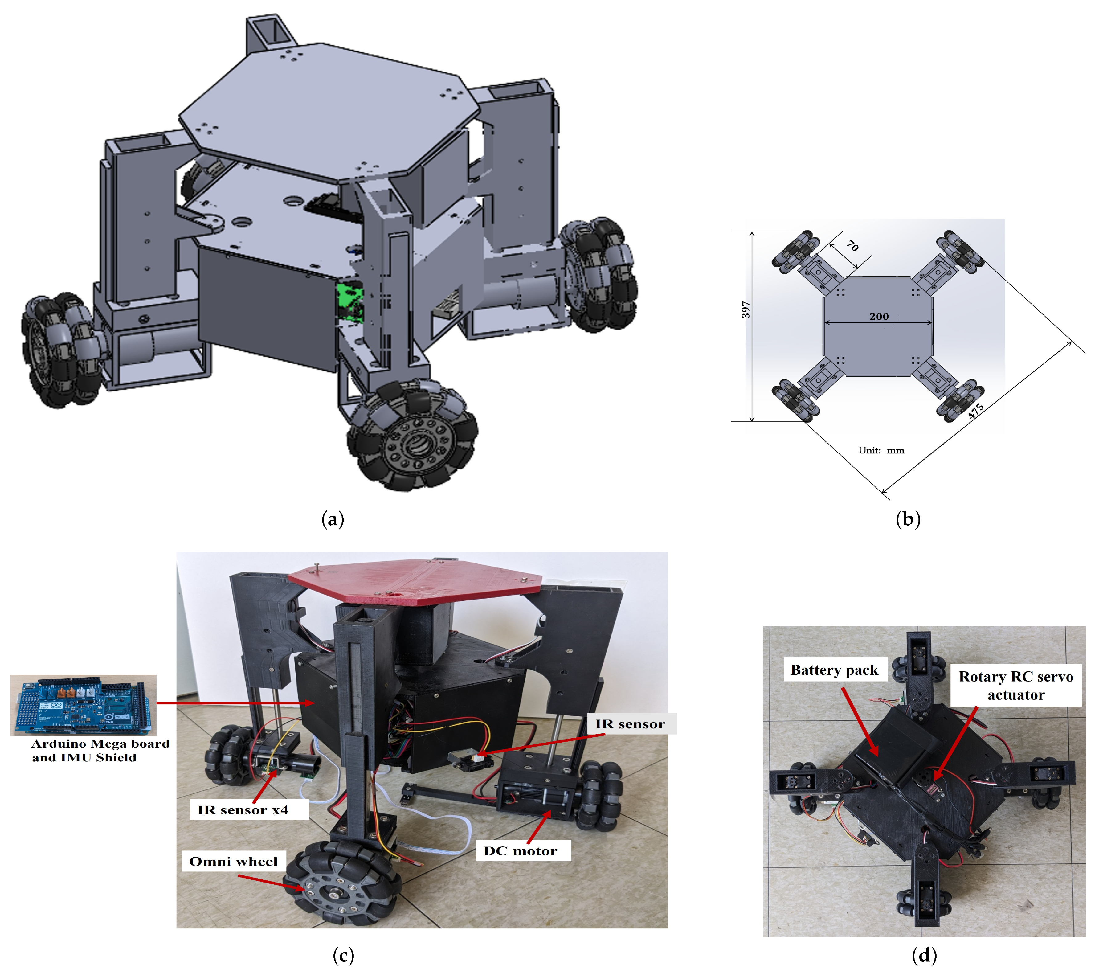
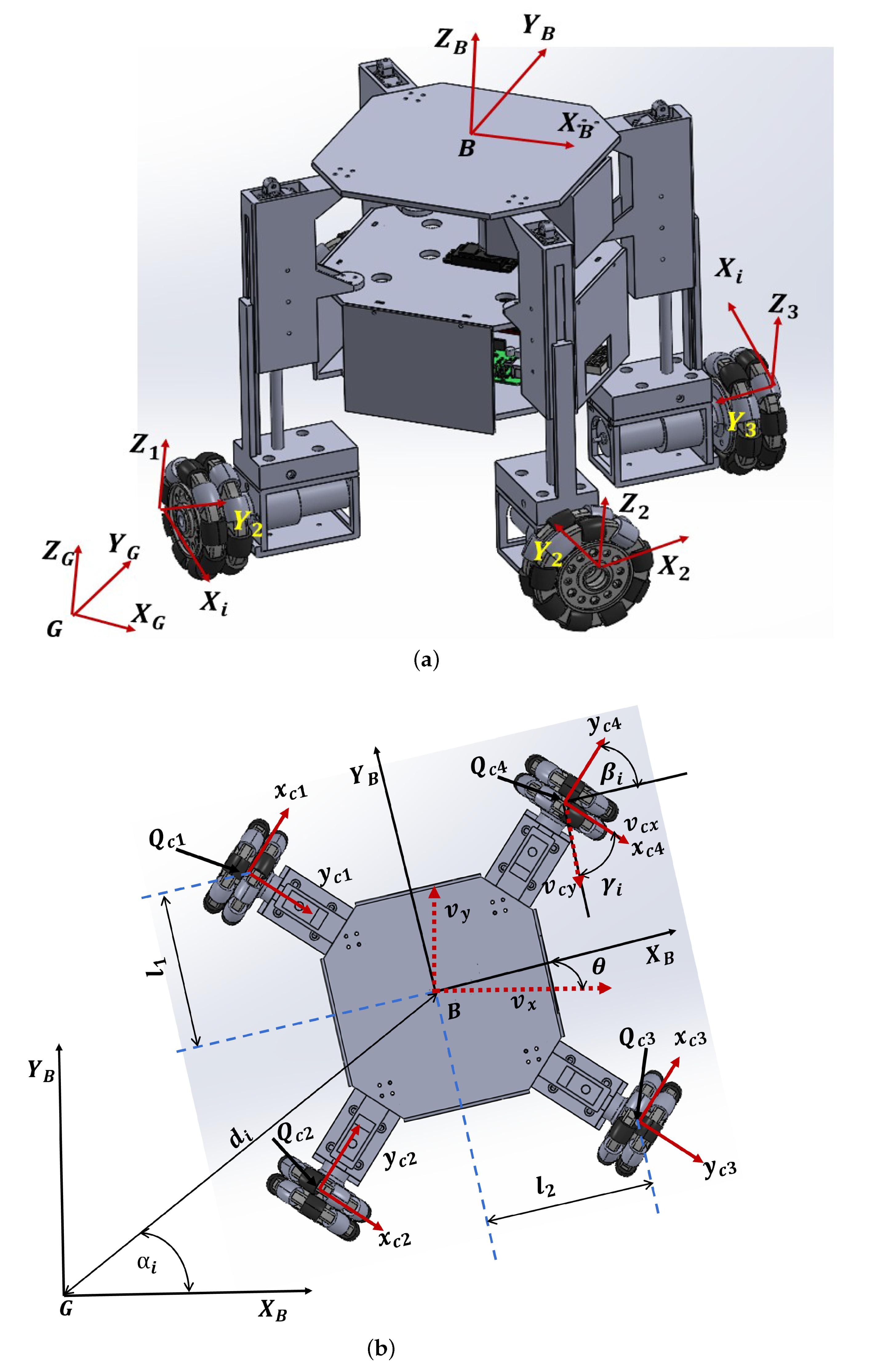
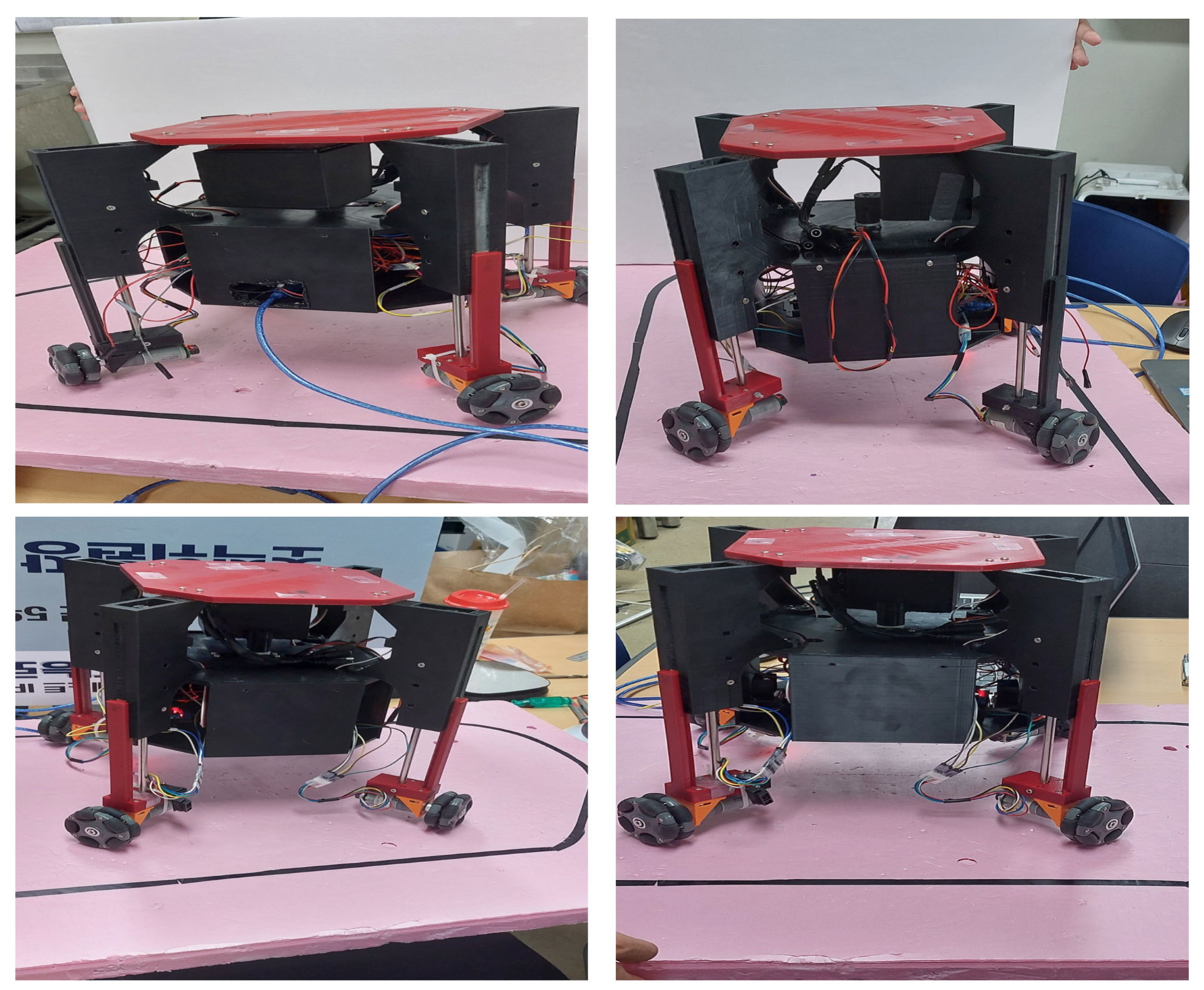
2.1. Conceptual Design
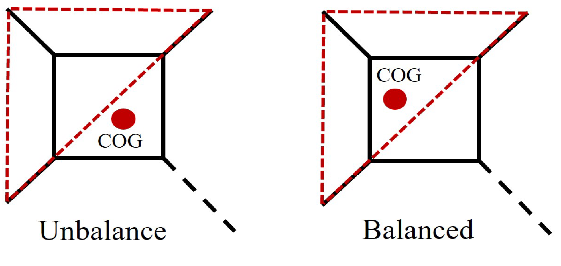
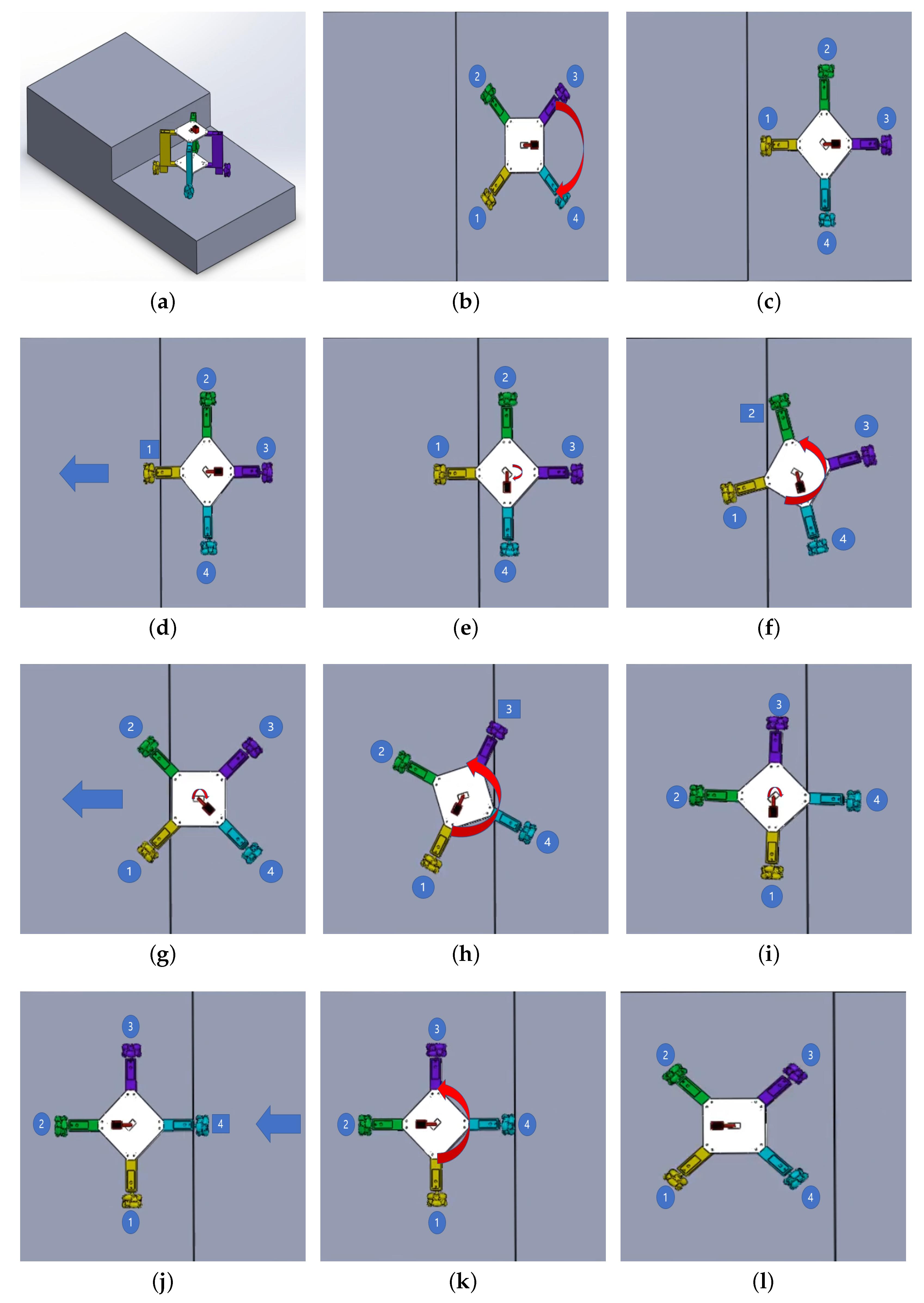
This study introduces the innovative design of a four-wheeled mobile robot consisting of four omni wheels, with each wheel connecting to a separate DC motor, as shown in Figure 1. The 3D model of the recommended prototype was created using SolidWorks™, as shown in Figure 1a. The overall dimensions of the robot are a height of 255 mm, a width of 397 mm, and a length of 475 mm, as shown in Figure 1b. Utilizing the capabilities and benefits offered by 3D printing technology, the study successfully designed and created a physical prototype of the system. The simulation results served as a basis for the design, and the 3D printing process allowed for the accurate realization of the prototype, with a weight of 4.5 Kg, as depicted in Figure 1c. Figure 1d shows the top view of the prototype, indicating the location of the rotary RC servo actuator.
To enable the robot to maintain a consistent speed, the proposed system incorporates a total of four omni wheels, with each wheel being connected to a dedicated DC motor. In addition, the system incorporates four linear RC servo actuators, which play a crucial role in facilitating the robot’s ability to climb stairs. the inclusion of a telescopic leg with a linear RC servo actuator allows the robot to adjust to different changes in the landscape, such as obstacle overcoming. Figure 2 shows the linear RC servo actuator and its housing. The extensive balancing responses facilitated by the linear RC servo actuators help to ensure that the robot’s center of mass remains within its base of support. Furthermore, the system includes a rotary RC servo actuator that allows for the adjustment of the center of mass, ensuring stability and effective climbing capabilities. Table 1 lists the parameters of the linear RC servo actuator, which includes a position sensor of a 10 KΩ linear potentiometer.

2.2. Gait Control

The creeping gait, a movement pattern for the proposed system, necessitates that a minimum of three wheels maintain contact with the ground continuously. The fourth wheel, linked to the linear RC servo actuator, advances using either quadrilateral or triangular support configurations [21]. In this research, we employed the creeping gait technique with a triangular support pattern for ascending stairs, illustrated in Figure 3.

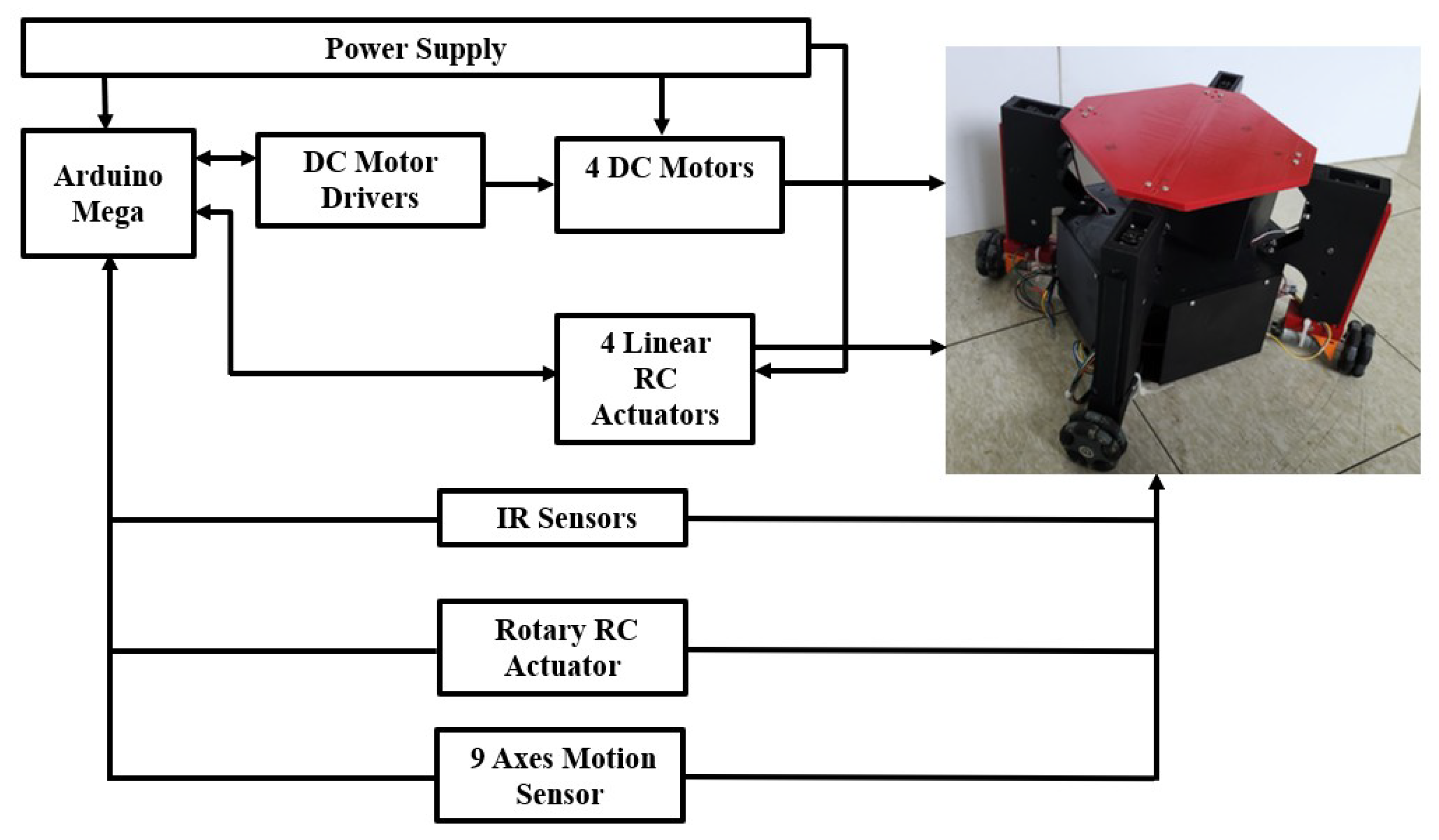
2.3. Control System Design

Figure 4 illustrates the control structure of the proposed system. It comprises several components, including a joystick module, an Arduino Mega microcontroller, four DC motors, DC motor drivers for the motors, a sensor shield, one rotary RC servo actuator, two Inertial Measurement Units (IMUs), four linear RC servo actuators, and a lipo power battery. We used four IR sensors, with one sensor attached to each leg to measure the height between the wheel and the ground, and another IR sensor to measure the distance from the body of the robot to the stair to confirm to the robot before starting the procedure for overcoming this stair. To construct the robot, 3D printing technology was utilized, employing polylactic acid (PLA) material for the mechanism parts.
The operator can give the robot direct commands to go forward, backward, left, right, and turn by using the joystick module. The DC motor driver interfaces with the Arduino Mega’s digital input–output sections, and the software controls the transmission of PWM signals to the motors based on the input from the control module. Each wheel has a motion drive motor, and an additional motor is included.

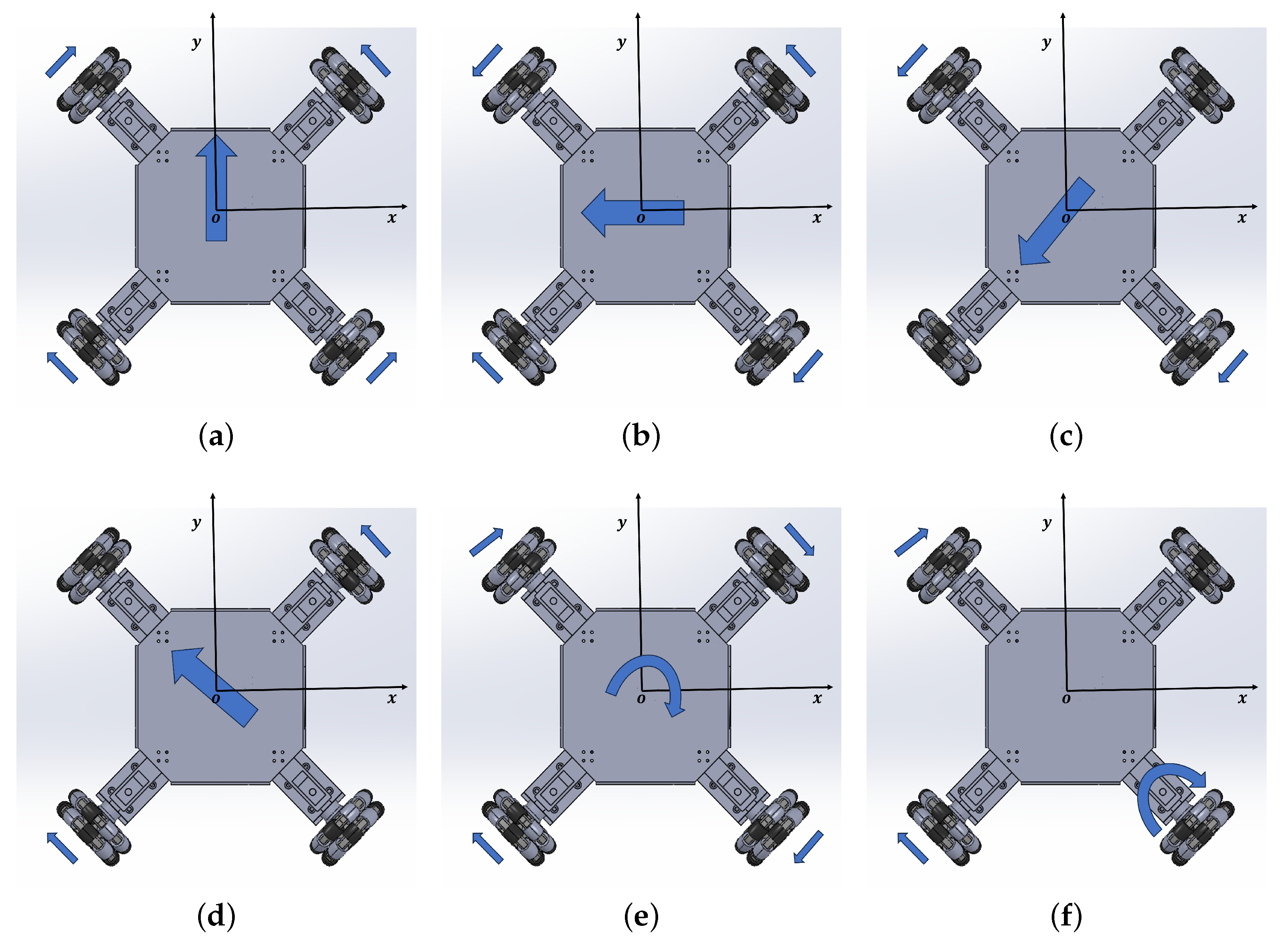
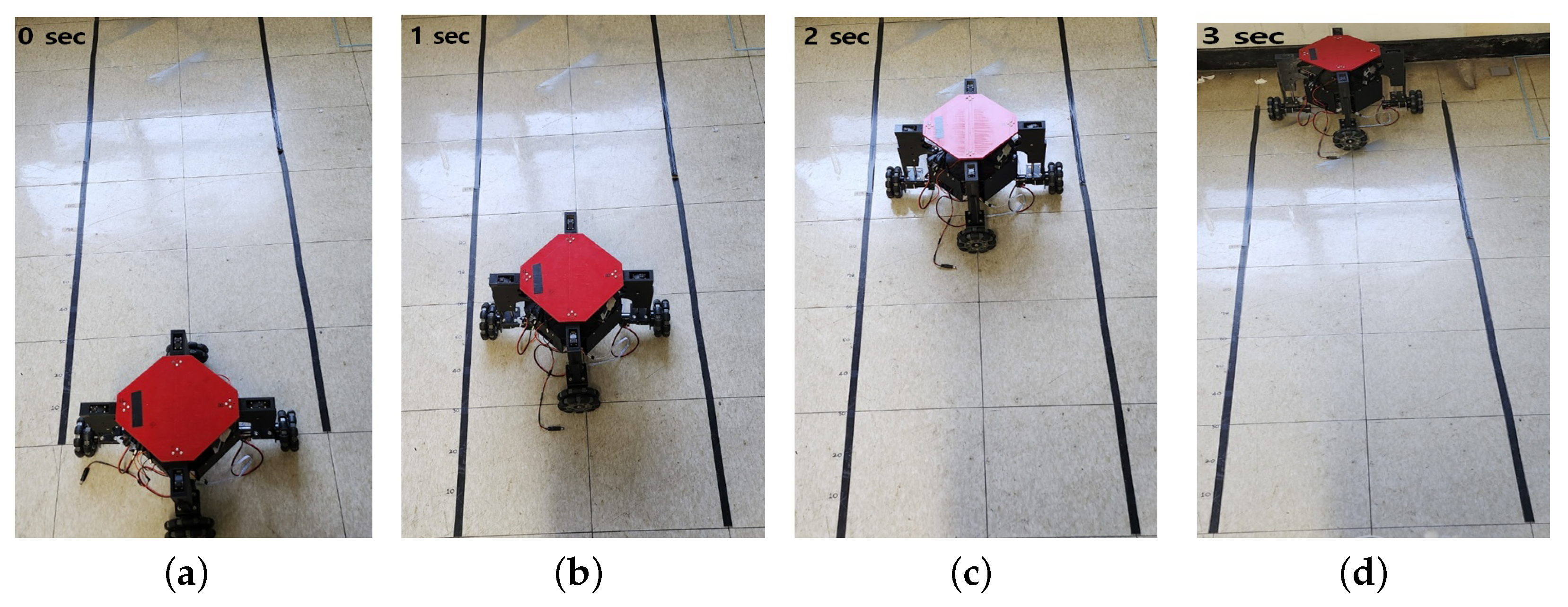
2.4. Locomotion Principle of the Robot

The four omni-wheeled mobile robot configuration is shown in Figure 5. The fixed reference frame of the robot is denoted as X G , G, Y G , while X B , B, Y B represent the reference frame associated with the mobile robot’s center of mass. In Figure 5a, each wheel has its coordinates. The x-axis represents the movement direction, the y-axis is the rotation axis about which the wheel rotates, and the z-axis represents the variable height of the linear actuator. Additionally, each wheel has a reference frame x c i , Q c i , and y c i , where i = 1 , 2 , 3 , 4 , as shown in Figure 5b. The model described here has been thoroughly investigated in the literature of [29]. We begin by describing the velocity of the i t h wheel in terms of its associated reference frame x c i , Q c i , y c i .
v x i = R ϕ i + v i r cos ( γ i )
v y i = v i r sin ( γ i )
Here, R i is the radius of the wheel; v x i and v y i are the wheel velocities along the x c -axis and y c -axis, respectively. v i r is the passive roller velocity, γ is the angle between the vectors v c x and v c y , and ϕ i is the angular velocity of the wheel where i = 1 , 2 , 3 , 4 . The angular velocity of each wheel can be obtained as follows [29].
ϕ 1 ϕ 2 ϕ 3 ϕ 4 = 1 R 1 1 ( l 1 + l 2 ) 1 1 ( l 1 + l 2 ) 1 1 ( l 1 + l 2 ) 1 1 ( l 1 + l 2 ) v x v y ϕ
Here, l 1 and l 2 are the distances between the wheels’ geometric centers and the center of the robot, v x is the linear velocity in the x direction, v y is the linear velocity in the y direction, and ϕ is the angular velocity of the robot. The linear velocities of the robot and its angular velocity are obtained by solving Equation (3), as follows.
v x = R 4 ϕ 1 + ϕ 2 + ϕ 3 + ϕ 4
v y = R 4 ϕ 1 + ϕ 2 + ϕ 3 ϕ 4
ϕ = R 4 ( l 1 + l 2 ) ϕ 1 + ϕ 2 ϕ 3 + ϕ 4
In Figure 6, the primary movements of an omni-wheeled robot are depicted in all directions. The side arrows indicate the wheel drive direction, while the central arrow shows the omni-wheeled robot’s moving direction. By independently setting the velocity and direction of each wheel, and maintaining the same velocity for all wheels simultaneously during operation, this robot can move in any direction without rotations. To move the robot forward, all four wheels were rotated in the same direction, as depicted in Figure 6a. To achieve lateral motion to the left, the left wheels were rotated inward against each other, while the right wheels were rotated outward against each other, as illustrated in Figure 6b. To move the robot diagonally at a 45° angle, the two wheels in the same direction were rotated in the same direction, while the other two wheels had a speed of zero, as shown in Figure 6c,d. To rotate around the center of the robot, the two right wheels were rotated in the same direction, while the two left wheels were rotated in the opposite direction, as shown in Figure 6e. The robot can rotate around the corner, as shown in Figure 6f. Additionally, to achieve a rotational motion between 0° and 360°, we adjust the speed of the diagonal wheel.

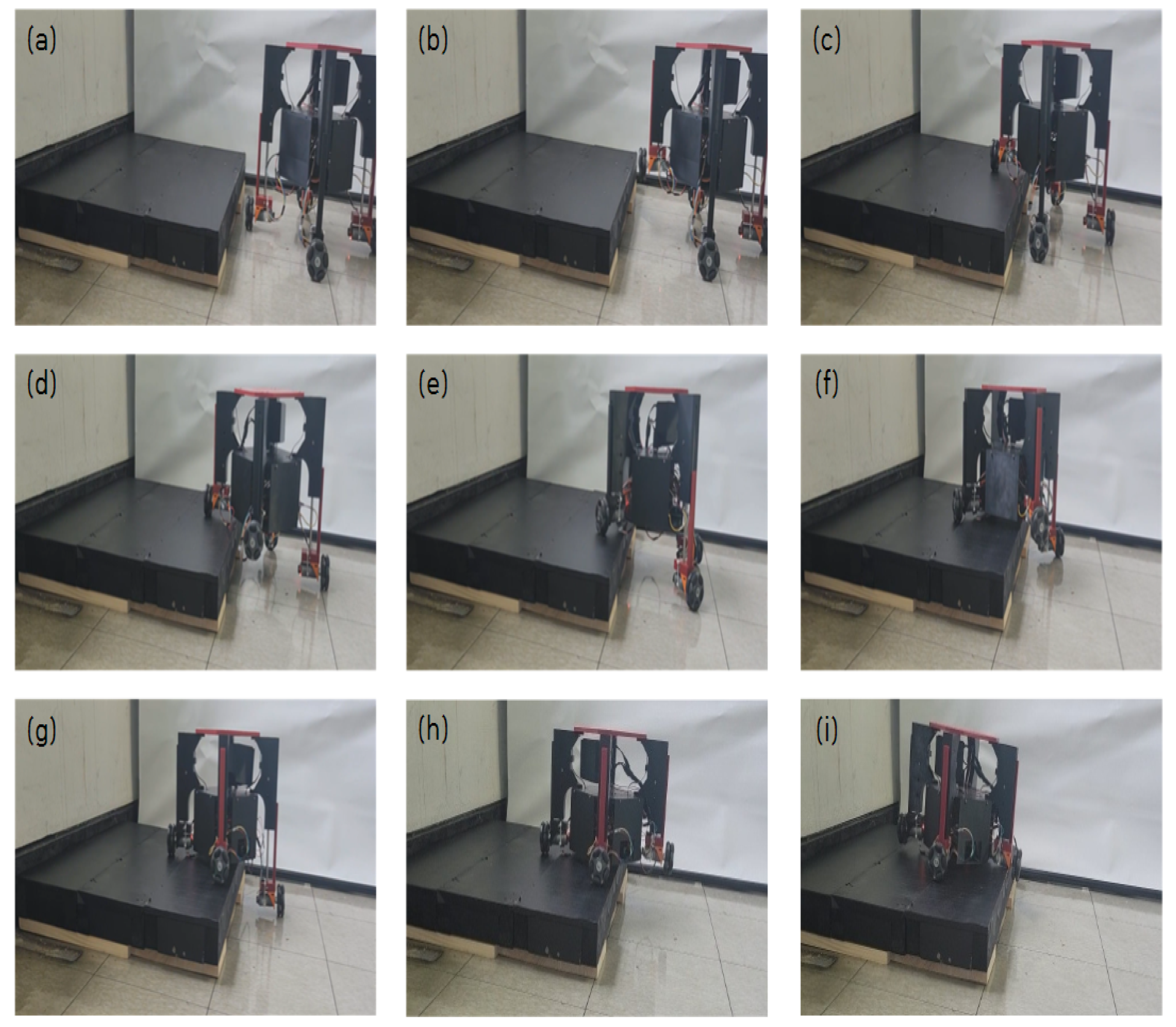
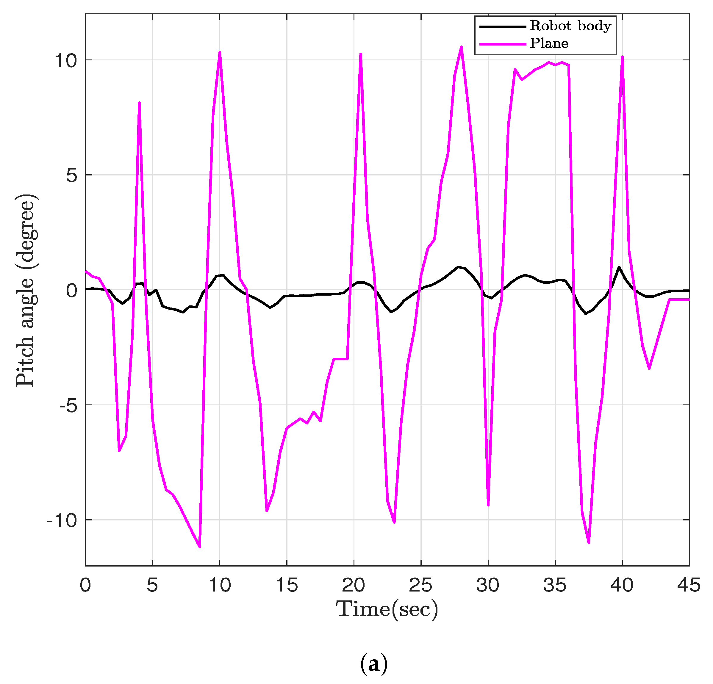
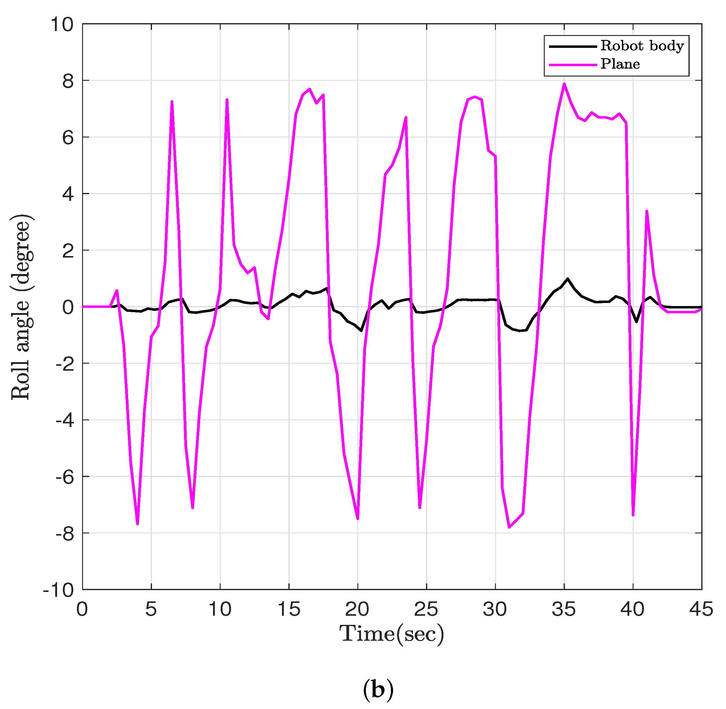
3. Simulation and Experimental Results

In this section, we present the simulation and experimental results of the suggested robot moving on level ground and ascending stairs. The robot is equipped with four DC motors, one rotary RC actuator, and four linear RC actuators. To assess the effectiveness of the proposed design, simulations were conducted using SolidWorks™ 2024 and the Matlab R2023b environment. These simulations were performed to validate the performance and capabilities of the proposed robot in ascending stairs. To successfully climb single steps, it is important to follow the sequence depicted in Figure 7, which includes frames (a to l). This sequence outlines the essential steps for a successful climb. Figure 7 presents a screenshot from a simulation, showcasing the performance of the obstacle overcoming of the system. A Supplemental Video is available to showcase these capabilities.
To assess the climbing capability of the proposed robot, we carried out an experiment focusing on evaluating its effectiveness in ascending stairs. To climb single steps, the sequence depicted in Figure 8 should be followed, encompassing frames (a to i). This sequence outlines the necessary steps for successful climbing. Initially, the robot will approach the stairs and position itself as depicted in frame (a). After approaching the step, the linear RC servo actuator will start moving upward, and simultaneously, the rotary RC servomotor will rotate to adjust the center of mass within the triangular region formed by the three wheels in contact with the ground. This adjustment is depicted in frame (b). Following the upward movement of the linear RC servo actuator, the robot will proceed to move in a straight line until it reaches the step, as shown in frame (c). In frame (d), the linear RC servo actuator will start moving upward, and simultaneously, the rotary RC servomotor will rotate to adjust the center of mass within the triangular region formed by the three wheels. Two wheels will remain in contact with the ground, while the third wheel will be on the surface of the stair step. Following the adjustments in frame (d), the robot will then turn counterclockwise, positioning two wheels on the stair surface and the other two wheels on the ground. This configuration is depicted in frame (e). After the counterclockwise turn in frame (e), the robot will continue moving forward until it reaches the step. At this point, the linear RC servo actuator will start moving upward, and the rotary RC servomotor will rotate to adjust the center of mass within the triangular region formed by the three wheels.
In frame (f), two wheels will remain in contact with the surface of the stair step, while the third wheel will be on the ground. This adjustment ensures stability and effective climbing of the stairs. In frame (g), following the adjustments in frame (f), the robot will make a counterclockwise turn. This maneuver will position three wheels in contact with the surface of the stair, ensuring stability and effective climbing. After the counterclockwise turn in frame (g), the linear RC servo actuator will begin to move upward, and simultaneously, the rotary RC servomotor will rotate to adjust the center of mass within the triangular region formed by the three wheels on the surface of the stair. This adjustment is depicted in frame h. After the adjustments in frame (h), the robot will proceed to move straight forward. This will be the final stage, where the robot successfully completes the climbing of the stairs. This stage is represented by frame (i). The experimental results for the linear motion are depicted in Figure 9, which showcases the captured video of the robot moving at a speed of 0.12 m/s. To control the robot’s body while dealing with external disturbances, we have conducted an experiment to evaluate the performance of the proposed robot. The robot was placed on a plate, and the disturbance was introduced by changing the angle of the plate, as shown in Figure 10. Two IMUs were used to measure the roll and pitch angles. The first IMU sensor was mounted inside the robot body, and the second IMU sensor was mounted on the plate. As shown in Figure 5a, the z-axis represents the variable height of the linear actuator, and we have four linear RC actuators with variable stroke length. When we apply a disturbance by changing the angle of the plate while needing to keep the robot body stable with roll and pitch angles being equal to zero, the stroke length of each linear RC actuator will change to guarantee this stability. As shown in Figure 11, the system is able to adjust the roll and pitch angles in response to orientation disturbances, effectively countering the disturbances and reducing the deviations at both angles to nearly zero.

4. Conclusions and Future Work

The study proposes that the design of the four-wheeled mobile robot consists of four omni wheels, with each wheel connecting to a separate DC motor. In addition, the presence of a telescopic leg with a linear RC servo drive enables the robot to adapt to various landscape changes, including obstacle overcoming. This paper discusses the mechanisms and performance associated with this design concept, presenting a proposed model. In view of the modeling and designing outcomes, a physical prototype was constructed to demonstrate its proficiency in both movement and stair climbing. The implementation of the design enables the robot to navigate both vertically and horizontally without the need to alter its orientation, resulting in improved stability and reliability during its operations. Experimental results further validate the robot’s effectiveness by showcasing its successful navigation and ascent of stairs. However, the limitation of the proposed design lies in the width of the robot and the stroke length of the linear RC actuator, which hinder its ability to climb conventional staircases or sets of multiple stairs. Instead, it can only overcome single steps with a height less than the stroke length of the linear RC actuator. In future work, we will concentrate on developing control strategies to enhance the robot’s autonomy and detection capabilities.

Supplementary Materials

The following supporting information can be downloaded at: https://www.mdpi.com/article/10.3390/machines13040292/s1.

Author Contributions

S.M. was responsible for the conceptualization, required resources, visualization, data handling, analyzing, investigation, experiments, preparation, writing the draft of the manuscript, and editing (review). K.K. was responsible for the experiments, formal analysis, and investigation. V.V. and Y.K. were responsible for the visualization, formal analysis, and investigation. B.S. was responsible for the funding acquisition, resources, and writing—reviewing, editing, and supervising. All authors have read and agreed to the published version of the manuscript.

Funding

This work was supported by the Basic Science Research Program through the National Research Foundation of Korea (NRF), funded by the Ministry of Education (2020R1I1A307033312).

Data Availability Statement

The raw data supporting the conclusions of this article will be made available by the authors on request.

Conflicts of Interest

The authors declare no conflicts of interest.

References

  1. Zhang, S.; Yao, J.T.; Wang, Y.B.; Liu, Z.S.; Xu, Y.D.; Zhao, Y.S. Design and motion analysis of reconfigurable wheel-legged mobile robot. Def. Technol. 2022, 18, 1023–1040. [Google Scholar]
  2. Seo, T.; Ryu, S.; Won, J.H.; Kim, Y.; Kim, H.S. Stair-Climbing Robots: A Review on Mechanism, Sensing, and Performance Evaluation. IEEE Access 2023, 11, 60539–60561. [Google Scholar] [CrossRef]
  3. Shi, Y.; Zhang, M.; Li, M.; Zhang, X. Design and Analysis of a Wheel-Leg Hybrid Robot with Passive Transformable Wheels. Symmetry 2023, 15, 800. [Google Scholar] [CrossRef]
  4. Mohamed, S.; Im, Y.; Shin, H.; Kim, Y.; Shin, B. Development of a novel quadruped hybrid wheeled-legged mobile robot with telescopic legs. Proc. Inst. Mech. Eng. Part C J. Mech. Eng. Sci. 2024, 238, 10785–10797. [Google Scholar] [CrossRef]
  5. Rubio, F.; Valero, F.; Llopis-Albert, C. A review of mobile robots: Concepts, methods, theoretical framework, and applications. Int. J. Adv. Robot. Syst. 2019, 16, 1729881419839596. [Google Scholar]
  6. Russo, M.; Ceccarelli, M. A Survey on Mechanical Solutions for Hybrid Mobile Robots. Robotics 2020, 9, 32. [Google Scholar] [CrossRef]
  7. Farooq, M.U.; Eizad, A.; Bae, H.K. Power solutions for autonomous mobile robots: A survey. Robot. Auton. Syst. 2023, 159, 104285. [Google Scholar]
  8. Mohamed, S.; Schäfle, T.R.; Uchiyama, N. Robust control of a redundant wheeled drive system for energy saving and fail safe motion. Adv. Mech. Eng. 2017, 9, 1687814017702343. [Google Scholar]
  9. Hijikata, M.; Miyagusuku, R.; Ozaki, K. Wheel arrangement of four omni wheel mobile robot for compactness. Appl. Sci. 2022, 12, 5798. [Google Scholar] [CrossRef]
  10. Bruzzone, L.; Baggetta, M.; Nodehi, S.E.; Bilancia, P.; Fanghella, P. Functional Design of a Hybrid Leg-Wheel-Track Ground Mobile Robot. Machines 2021, 9, 10. [Google Scholar] [CrossRef]
  11. Quaglia, G.; Visconte, C.; Scimmi, L.S.; Melchiorre, M.; Cavallone, P.; Pastorelli, S. Design of a UGV powered by solar energy for precision agriculture. Robotics 2020, 9, 13. [Google Scholar] [CrossRef]
  12. Mohamed, S.; Quang Le, H.; Kim, Y.; Shin, B. Design and modeling of hexapod robot using telescopic legs connected to pivot joints at the hips. Proc. Inst. Mech. Eng. Part C J. Mech. Eng. Sci. 2024, 238, 3480–3497. [Google Scholar] [CrossRef]
  13. Hijikata, M.; Miyagusuku, R.; Ozaki, K. Omni wheel arrangement evaluation method using velocity moments. Appl. Sci. 2023, 13, 1584. [Google Scholar] [CrossRef]
  14. Sun, T.; Xiang, X.; Su, W.; Wu, H.; Song, Y. A transformable wheel-legged mobile robot: Design, analysis and experiment. Robot. Auton. Syst. 2017, 98, 30–41. [Google Scholar] [CrossRef]
  15. Mertyüz, I.; Tanyıldızı, A.K.; Taşar, B.; Tatar, A.B.; Yakut, O. FUHAR: A transformable wheel-legged hybrid mobile robot. Robot. Auton. Syst. 2020, 133, 103627. [Google Scholar] [CrossRef]
  16. Wilk-Jakubowski, G.; Harabin, R.; Ivanov, S. Robotics in crisis management: A review. Technol. Soc. 2022, 68, 101935. [Google Scholar] [CrossRef]
  17. Shen, S.Y.; Li, C.H.; Cheng, C.C.; Lu, J.C.; Wang, S.F.; Lin, P.C. Design of a leg-wheel hybrid mobile platform. In Proceedings of the 2009 IEEE/RSJ International Conference on Intelligent Robots and Systems, St. Louis, MO, USA, 10–15 October 2009; pp. 4682–4687. [Google Scholar]
  18. Wen, H.; Yang, H.; Chen, Y.; Zhou, L.; Wu, D. A robot with decoupled mechanical structure and adapted state machine control for both ground and staircase situations. Appl. Sci. 2019, 9, 5185. [Google Scholar] [CrossRef]
  19. Zhang, Q.; Ge, S.S.; Tao, P.Y. Autonomous stair climbing for mobile tracked robot. In Proceedings of the 2011 IEEE International Symposium on Safety, Security, and Rescue Robotics, Kyoto, Japan, 1–5 November 2011; pp. 92–98. [Google Scholar]
  20. Yang, D.; Bewley, T. A minimalist Stair Climbing Robot (SCR) formed as a leg balancing & climbing Mobile Inverted Pendulum (MIP). In Proceedings of the 2018 IEEE/RSJ International Conference on Intelligent Robots and Systems (IROS), Madrid, Spain, 1–5 October 2018; pp. 2464–2469. [Google Scholar]
  21. Liu, F.; Wu, D.; Chen, K. The simplest creeping gait for a quadruped robot. Proc. Inst. Mech. Eng. Part C J. Mech. Eng. Sci. 2012, 227, 170–177. [Google Scholar] [CrossRef]
  22. Mihankhah, E.; Kalantari, A.; Aboosaeedan, E.; Taghirad, H.; Ali, S.; Moosavian, A. Autonomous staircase detection and stair climbing for a tracked mobile robot using fuzzy controller. In Proceedings of the 2008 IEEE International Conference on Robotics and Biomimetics, Bangkok, Thailand, 22–25 February 2009; pp. 1980–1985. [Google Scholar]
  23. Ma, Y.; Lyu, F. Design of A Wheel-Legged Stair Climbing Robot. In Proceedings of the 2021 7th International Conference on Control, Automation and Robotics (ICCAR), Singapore, 23–26 April 2021; pp. 146–150. [Google Scholar] [CrossRef]
  24. Tanaka, M.; Tanaka, K. Stair climbing of an articulated mobile robot via sequential shift. In Proceedings of the 2015 IEEE/SICE International Symposium on System Integration (SII), Nagoya, Japan, 11–13 December 2015; pp. 877–881. [Google Scholar]
  25. Baishya, N.J.; Bhattacharya, B.; Ogai, H.; Tatsumi, K. Analysis and Design of a Minimalist Step Climbing Robot. Appl. Sci. 2021, 11, 7044. [Google Scholar] [CrossRef]
  26. Wei, Y.; Lee, K. CLAW: Cycloidal Legs-Augmented Wheels for Stair and Obstacle Climbing in Mobile Robots. IEEE/ASME Trans. Mechatron. 2024, 1–11. [Google Scholar] [CrossRef]
  27. Kim, D.; Hong, H.; Kim, H.S.; Kim, J. Optimal design and kinetic analysis of a stair-climbing mobile robot with rocker-bogie mechanism. Mech. Mach. Theory 2012, 50, 90–108. [Google Scholar] [CrossRef]
  28. Pappalettera, A.; Reina, G.; Mantriota, G. Design and Analysis of Tracked Stair-Climbing Robot Using Innovative Suspension System. Robotics 2024, 13, 45. [Google Scholar] [CrossRef]
  29. Taheri, H.; Qiao, B.; Ghaeminezhad, N. Kinematic model of a four mecanum wheeled mobile robot. Int. J. Comput. Appl. 2015, 113, 6–9. [Google Scholar] [CrossRef]
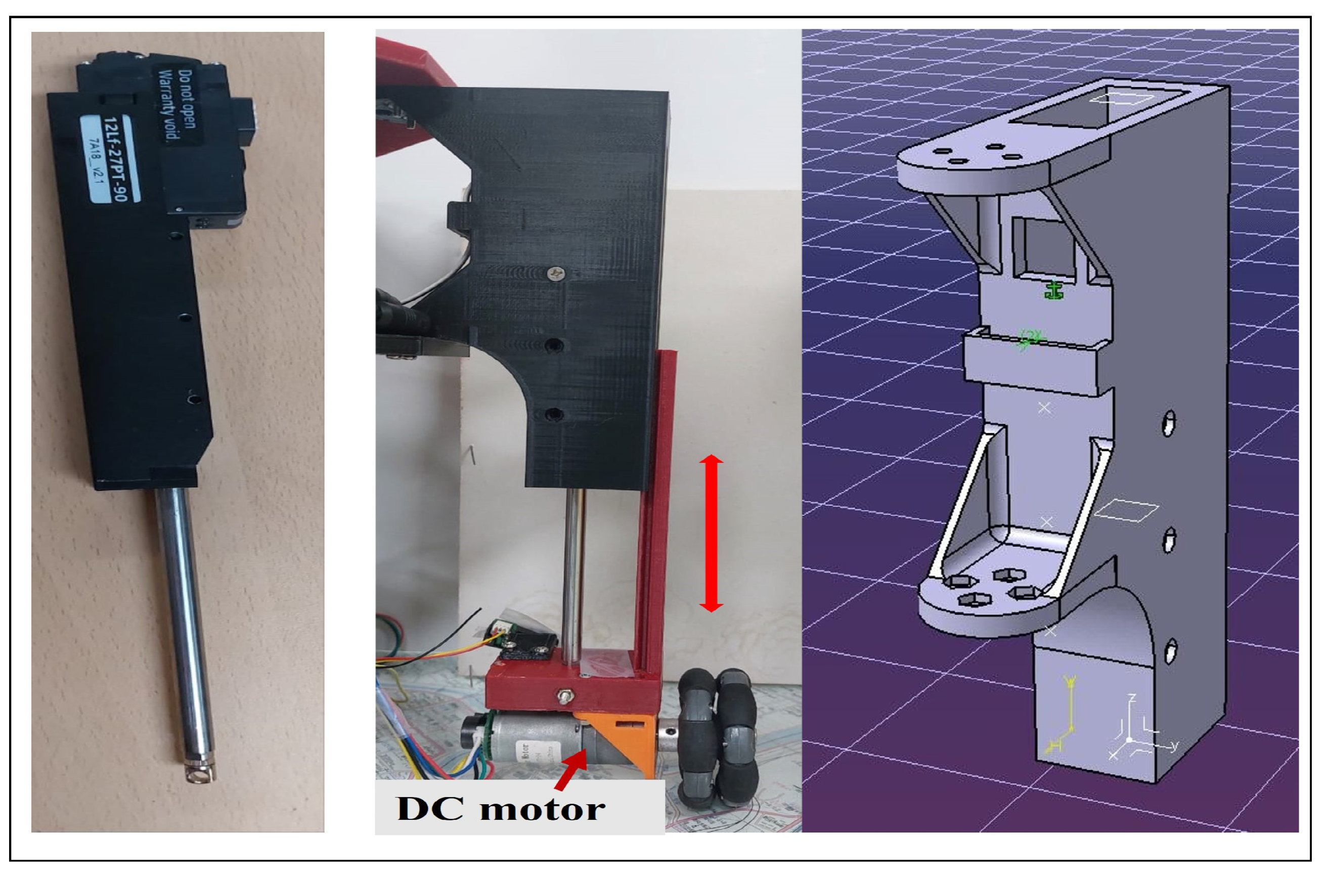
Figure 1. Proposed robot: (a) 3D model, (b) top view of 3D model, (c) physical prototype, and (d) top view of physical prototype.
Machines 13 00292 g001
Figure 2. Linear RC servo actuator and its housing.
Machines 13 00292 g002
Figure 3. Creep gait pattern.
Machines 13 00292 g003
Figure 4. Schematic of the control hardware scheme of the proposed system.
Machines 13 00292 g004
Figure 5. Four omni-wheeled mobile robot configuration: (a) isometric view, and (b) top view.
Machines 13 00292 g005
Figure 6. Principal movements directions of the proposed system: (a) forward, (b) right-lift, (c,d) moving at a 45° angle, (e) rotating around the center of the robot, and (f) rotating around a corner.
Machines 13 00292 g006
Figure 7. Video capture: simulation results of stair-climbing performance: (a) isometric view of initial position, (b) top view of initial position, (ck), sequence steps of climbing the step procedures, (l) finally the robot climbs the step.
Machines 13 00292 g007
Figure 8. Video capture: experimental results of stair-climbing (single step) performance of the proposed robot: (a) initial position, (bh), sequence steps of climbing the step procedures, (i) finally the robot climbs the step.
Machines 13 00292 g008
Figure 9. Video capture: experimental results for linear motion: (a) starting position, (b) the robot position at time = 1 s, (c), the robot position at time = 2 s, and (d) goal position at time = 3 s.
Machines 13 00292 g009
Figure 10. Video capture of experimental outcomes: interferences induced by variations in the plate’s angle.
Machines 13 00292 g010
Figure 11. Experimental results of the center of body: (a) pitch angle and (b) roll angle under disturbance.
Machines 13 00292 g011aMachines 13 00292 g011b
Table 1. Specification of the linear RC servo motor.
ParameterValueUnit
Max Speed (no load)28mm/s
Related load27N
Input Voltage12V
Positional accuracy (unidirectional)50μm
Gear Ratio10:1-
Size151.5 (L) × 36 (W) × 18 (H)mm
WeightApprox. 177g
Stroke90mm
Motor Watt26W
Stall Force at Current (1.6 A/800 mA/1000 mA)160/96/12.8N
Disclaimer/Publisher’s Note: The statements, opinions and data contained in all publications are solely those of the individual author(s) and contributor(s) and not of MDPI and/or the editor(s). MDPI and/or the editor(s) disclaim responsibility for any injury to people or property resulting from any ideas, methods, instructions or products referred to in the content.

