Abstract
Thermal elongation in high-speed motorized spindles constitutes a major source of machining error in five-axis machine tools, critically impacting machining precision. This study aims to develop and validate a cumulative thermal error compensation model for predicting spindle thermal elongation, subsequently enabling effective compensation via a dedicated control algorithm. Key thermal error factors, primarily spindle speed and cumulative thermal error, were identified through analysis. An innovative numerical prediction model incorporating these factors was established. Its performance was evaluated through experiments utilizing eddy-current displacement sensors for high-speed, high-precision thermal elongation measurement. The validation results demonstrated the model’s strong predictive capability: During spindle startup, prediction errors exhibited minor transients, stabilizing near zero once the operating speed was reached. Under dynamic speed changes, the maximum prediction error was only 1.28 μm, with the overall maximum residual error recorded at 2.04 μm. These findings confirm the model’s high accuracy. Furthermore, the model exhibits excellent generalization capability, delivering significant compensation effectiveness across diverse variable-speed operating conditions. This work successfully developed a highly accurate numerical model and a practical compensation strategy, significantly enhancing the positioning accuracy of high-speed spindles against thermal disturbances. The proposed approach offers substantial engineering utility for thermal error compensation in precision machining applications.
1. Introduction
With the increasing demand for submicron-level machining accuracy [1], thermal deformation errors now account for over 62% of total machining inaccuracies [2]. As the primary heat source, the axial thermal elongation of machine tool spindles contributes up to 80% of the total tool-workpiece positioning errors [3]. However, conventional temperature-based compensation systems face two inherent limitations: 1. Pre-embedded temperature sensors require intrusive spindle redesign [4], hindering retrofitting of existing equipment; 2. Multi-physics coupling induces significant time hysteresis (3.5–8.2 s) in the temperature-elongation relationship [5], critically compromising real-time compensation efficacy.
Current thermal compensation strategies can be broadly categorized into two technical paths: academic efforts focused on enhanced thermal modeling, exemplified by the gray preprocessed neural network [6], and genetic-algorithm-optimized wavelet neural networks [7]. Nevertheless, these approaches demand 4–7 temperature measurement points while exhibiting compensation delays exceeding 300 ms [8]. Industrial implementations explore signal substitution, as evidenced by rotational speed-based thermal prediction models [9]; however, these fail to adequately address cumulative effect modeling under variable-speed conditions.
Established compensation methods encounter three implementation barriers [10]:
- Computational limitations of embedded systems for complex model deployment;
- Sensor cabling-induced spindle imbalance;
- Restricted algorithm portability in proprietary CNC systems [11].
Significantly, recent studies reveal a 0.913 Pearson correlation between spindle encoder signals and thermal elongation [12], suggesting promising alternatives to sensor-dependent approaches.
This study proposes a paradigm-shifting dynamic memory compensation (DMC) mechanism featuring two key innovations:
- Iterative modeling of spindle speed (n) and historical elongation (St) eliminates the need for temperature sensing [3];
- The cumulative thermal elongation compensation model, utilizing spindle test data across multiple rotational speeds, demonstrates robust predictive capability under varying-speed machine tool operations due to its inherent deformation accumulation mechanism [13].
Experimental validation across designed-speed, step-variable, and stochastic disturbance conditions demonstrates 76.3% reduction in post-compensation error standard deviation.
2. Spindle Thermal Error Prediction Model
2.1. Natural Exponential Prediction Model
Extensive experimental studies on spindle thermal elongation testing and compensation conducted by researchers [14,15,16,17] have revealed that thermal elongation under constant rotational speed follows an exponential pattern. The natural exponential function is therefore adopted to formulate the thermal elongation prediction model, as expressed in Equation (1):
where S denotes the spindle thermal elongation, represents the initial thermal displacement, is the steady-state elongation under constant speed, t indicates machine operation time, and signifies the thermal equilibrium time constant.
To ensure compatibility with multiple constant-speed conditions, the relationship between steady-state elongation () and rotational speed () is fitted using polynomial regression:
where , , and are fitting coefficients. The model degenerates to a linear form when = 0.
For cold-start conditions ( = 0), substituting Equation (2) into Equation (1) yields the operational prediction model:
This model characterizes thermal elongation through two independent variables: rotational speed () and time (t). The required compensation displacement A for CNC systems satisfies A = −S.
The model exclusively applies to constant-speed operations. Any rotational speed variation invalidates the prediction framework, and reinitialization of model parameters is mandatory for variable-speed conditions, significantly restricting practical implementation in dynamic machining processes.
2.2. Support Vector Regression Model
Support Vector Regression (SVR), derived from Support Vector Machines (SVMs), is a robust regression tool in statistical learning theory. By implementing the principle of structural risk minimization, SVR effectively addresses overfitting and extended training duration in machine learning while avoiding local minima issues inherent in neural network approaches. The fundamental paradigm involves constructing a hyperplane with an ε-insensitive zone, where the optimal hyperplane minimizes the maximal distance to sample points while constraining prediction errors within a predefined tolerance threshold.
The optimization objective follows an ε-insensitive loss function: no penalty is applied to residuals within the ε-tube, whereas deviations exceeding ±ε incur linear penalties. Through kernel functions (e.g., Gaussian, polynomial), nonlinear regression problems are projected into higher-dimensional feature spaces for linear separation. The primal optimization problem with constraints is formulated as Equation (4):
In the equation, xi is the feature vector, yi is the target value, C is the penalty factor (which can be adjusted), and the slack variables ξi and ξi* are introduced.
2.3. RBF Neural Network Thermal Error Model with Chicken Swarm Optimization
A Radial Basis Function (RBF) neural network integrated with Chicken Swarm Optimization (CSO), termed CSO-RBF, is developed for comprehensive thermal error modeling. The CSO algorithm mimics hierarchical flock dynamics and behavioral patterns, where the swarm is divided into subgroups based on fitness values. Each subgroup comprises one rooster (highest fitness), multiple hens, and chicks (lowest fitness). Distinct motion rules govern each role: roosters lead foraging, hens follow stochastic subgroup assignments, and chicks establish random maternal relationships. This biomimetic hierarchy enables swarm intelligence optimization through inter-group competition and intra-group cooperation.
The RBF neural network adopts a three-layer feedforward architecture (Figure 1):
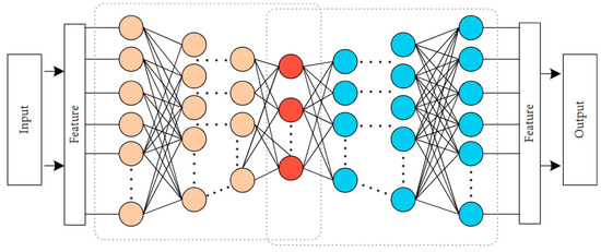
Figure 1.
Architecture of RBF Neural Network.
The fundamental principle can be articulated as follows: Through basis functions, nonlinearly separable variables in low-dimensional space are directly transformed into a high-dimensional feature space to achieve linear separability. This process does not require weight connections, enabling the RBF neural network to establish a nonlinear mapping relationship between inputs and outputs. Although the mapping is nonlinear, the network output can still be expressed as a linear combination of adjustable parameters. This characteristic allows network weights to be directly determined by solving linear equations, which not only significantly enhances training efficiency but also effectively avoids local optima.
Assuming the input of the RBF neural network is , the hidden layer can be expressed as:
where denotes the radial basis function (RBF), typically chosen as an n-dimensional Gaussian function. The mathematical expression is formulated as:
where X denotes n input variables, represents the center of the j-th basis function, and indicates the width of the j-th basis function. Based on the linear relationship between the output layer and hidden layer, the output of the RBF neural network can be expressed as:
where Wj denotes the weight combination between the hidden and output layers of the RBF neural network, and is the network’s output. Additionally, the sum of differences between the actual output Yactual and the desired output Ydesired is adopted as the fitness function in the Chicken Swarm Optimization (CSO) algorithm during the structural parameter optimization of the RBF neural network. The mathematical formulation is given by:
where n denotes the iteration count, Di represents the desired output value in the data sample for the i-th iteration, Yi indicates the actual output result of the RBF neural network at the i-th iteration.
2.4. Cumulative Thermal Elongation Compensation Model
The thermal elongation rate of motorized spindles exhibits a proportional correlation with the temperature rise rate, which is predominantly determined by the equilibrium state between heat generation and dissipation rates. Within spindle systems, motors and bearings constitute the primary heat generation components [18]. Analysis of heat generation in motors reveals that hysteresis losses and windage friction losses demonstrate linear proportionality with spindle rotational speed, while eddy current losses exhibit quadratic proportionality relative to rotational speed [19,20,21,22,23]. For bearing heat generation, the frictional torque induced by spindle rotation-induced bearing loads shows cubic proportionality to rotational speed, whereas other load-induced frictional torque and lubricant viscosity-related friction display linear proportionality.
Spindle thermal dissipation primarily consists of two mechanisms: forced heat dissipation through coolant channels and natural convection with ambient air. The thermal elongation rate demonstrates significant variation under different operational conditions. When spindle rotation ceases (zero rotational speed), heat generation terms become null, rendering the thermal elongation rate dependent solely on dissipation components. Post-operation residual heat persists within the spindle, with forced or natural cooling inducing thermal contraction whose contraction rate depends exclusively on the accumulated thermal elongation at shutdown.
During spindle operation, the dissipation term is influenced not only by accumulated thermal elongation from previous states but also by rotational speed. Consequently, the principal factors governing spindle thermal elongation rate are rotational speed and cumulative thermal error, expressible as:
where S is the thermal elongation of the spindle, is the spindle speed, and , …, are coefficients. The first and last terms are related to the heat dissipation of the spindle system, while , , and are related to the heat generation of the spindle system. Taking the rotational speed sampling time as Δt, Equation (10) becomes:
Let , , , ; then Equation (11) can be expressed as:
where is the thermal displacement at the current time step, and is the thermal displacement at the previous time step. Through and rotational speed , the real-time thermal displacement can be calculated. The determination of coefficients, , …, can be obtained via regression analysis using data measured from multiple sets of experiments.
The spindle prediction model established by Equation (12) is a function of rotational speed and cumulative thermal elongation of the spindle. When compensating for the machine tool system, the spindle offset compensation value is used to counteract the thermal elongation obtained from the prediction model, with the following relationship between them:
2.5. Comparison and Summary
The four prediction models discussed above function as follows:
The natural exponential function prediction model establishes the relationship between thermal elongation and time based on rotational speed and the equilibrium time constant at constant spindle speed. While offering certain compensation effects, its limitations are significant. This stems from the high correlation between spindle thermal elongation and machining operational conditions. The model only applies to constant-speed conditions and cannot adapt to random variable-speed working conditions, exhibiting poor compatibility and limited generalizability.
Support Vector Regression (SVR) models not only require numerous conditions, have complex model structures, and lack generalizability, but also face practical implementation challenges in real machine tool machining scenarios. Since temperature sensors are not installed at the internal bearings of the motorized spindle, real-time temperature changes at bearing locations cannot be acquired. Using external sensors would interfere with normal machine tool machining. Consequently, this modeling method lacks implementability in practical applications.
CSO-RBF neural network models typically require extensive historical data and high-quality experimental data, which impacts actual production efficiency in factory settings. Meeting micron-level precision requirements for five-axis ultra-precision machine tools necessitates transmitting real-time collected data to the control system to calculate and compensate for current thermal errors. Due to the complexity of the CSO algorithm, the model is incapable of prompt responsiveness to dynamic system changes.
The cumulative thermal elongation compensation model relies on thermal elongation test data from multiple spindle speed groups. Since thermal deformation is cumulative, this model maintains strong predictive capabilities even under various variable-speed working conditions. Aimed to investigate factors influencing the thermal elongation of motorized spindles and establish a thermal error prediction model with strong predictive capability, high practicality, and robustness, we establishes a cumulative thermal elongation compensation model suitable for variable-speed conditions, based on rotational speed and cumulative thermal elongation from the previous time step. Variable-speed experiments are designed to verify the model’s predictive performance under specified working conditions.
3. Measurement System and Experimental Scheme Design
3.1. Thermal Elongation Measurement System Design
The motorized spindle axial thermal elongation measurement device utilizes an eddy current displacement sensor. An eddy current displacement sensor is commonly employed for measuring minute surface displacements of metallic materials. It typically comprises a power supply, coil, and sensing probe. When energized, the coil generates a high-frequency alternating electromagnetic field that penetrates the surface of the measured metal, inducing eddy currents. Displacement of the target object alters the eddy current induction characteristics, thereby modifying the electromagnetic field properties. The sensing probe detects this variation, determining displacement magnitude through electromagnetic field measurements. Eddy current displacement sensors exhibit high sensitivity, non-contact measurement capability, high precision, and good stability. The eddy current displacement sensor was calibrated prior to the experiments using a high-precision laser interferometer to ensure measurement accuracy. The physical configuration of the measurement setup is illustrated in Figure 2. 5-axis vertical machining center used in this experiment, model SF260H, manufactured by Jiangxi JUST Numerical Control Co., Ltd. (Nanchang, China). Specifications include a 260 mm diameter rotary table, and XYZ axis travel ranges of 700 mm, 500 mm, and 360 mm, respectively, with repetitive positioning accuracy of less than 1 μm.
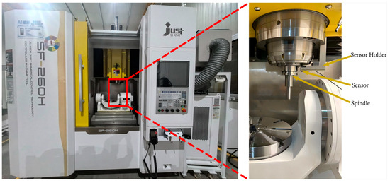
Figure 2.
Physical Configuration of Thermal Elongation Measurement Setup.
By mounting the eddy current displacement sensor on a bracket and securing the bracket to the motorized spindle end, the displacement variation during thermal elongation of the spindle can be directly measured. This configuration features rapid response time and high precision. The parameters of the eddy current displacement sensor are provided in Table 1.

Table 1.
Specific Parameters of the Sensor and spindle.
3.2. Experimental Scheme Design
The experiment was conducted in a constant-temperature workshop at 22 ± 1 °C with cooling water temperature set at 24 °C. During testing, the motorized spindle operated under no-load conditions. To control the spindle under different working states, programmed sequences repeatedly executed: spindle start-up → speed increase → speed reduction → shutdown. The rotational speed settings are illustrated in Figure 3, with each speed maintained for approximately 20 min. No specific warm-up procedure was performed prior to the experiments. The spindle was started from a cold state at the beginning of each test to capture the thermal elongation behavior from initial conditions. Thermal displacement data was recorded 20 times per speed before transitioning to the next state.
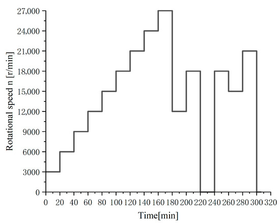
Figure 3.
Schematic of time–spindle speed relationship.
As discernible from Figure 3, the spindle speed design comprises three phases. In the first phase, the rotational speed progressively increases from an initial 3000 r/min, rising by 3000 r/min per 20-min interval until reaching 27,000 r/min. The second phase involves two abrupt speed reduction processes: the first plummets from 27,000 r/min to 12,000 r/min, and the second drops directly from 18,000 r/min to 0 r/min. The third phase is designed as a fluctuating speed working condition, exhibiting acceleration followed by deceleration and re-acceleration.
4. Results
Thermal elongation measurements obtained via eddy current displacement sensors under the designed speed conditions are shown in Figure 4. Note: Negative values indicate downward thermal elongation.
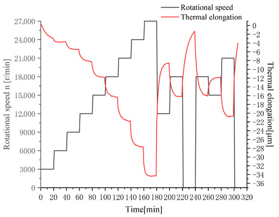
Figure 4.
Experimental data of spindle speed–thermal elongation.
Figure 3 reveals sharp thermal elongation variations at spindle speed transition points. During Phase 1 (0–180 min), rotational speed progressively increased from 3000 r/min to 27,000 r/min, with spindle thermal elongation continuously rising to 34.4 μm at 180 min. In Phase 2 (180–240 min), an abrupt speed reduction to 12,000 r/min triggered the most significant thermal elongation shift: decreasing to 17.9 μm within 1 min (16.5 μm abrupt drop). Thermal elongation gradually decreased during spindle shutdown, with slower temporal variation, ultimately reaching 1.1 μm at shutdown. During Phase 3 (240–300 min), under cyclic acceleration/deceleration conditions, thermal elongation exhibited cyclical increase-decrease variations. Final elongation stabilized at 4.1 μm in shutdown state.
The spindle rotational speed–thermal elongation experimental data were used for fitting the cumulative thermal elongation compensation model. The model satisfies Equation (6). As indicated by the equation, establishing this spindle compensation model requires determining the parameter values …, . The whole range of data obtained from experiments were imported into SPSS 26 software for multiple linear regression. The determined parameter values are shown in Table 2, with the model achieving a coefficient of determination (R2) of 0.998.
Table 2.
Spindle Compensation Model Parameter Values.
The expression of the cumulative thermal error spindle compensation model, determined by the parameter values obtained from Table 2, is
The axial thermal elongation of the motorized spindle at the current time step can be predicted based on the spindle’s current rotational speed and the cumulative thermal error from the previous time step using Equation (13).
5. Discussion
To validate the effectiveness of the aforementioned cumulative thermal compensation model, the spindle was driven to operate under two operating conditions: the designed operating condition and random rotational speed.
The cumulative thermal elongation prediction model was fitted using the test data from multiple variable-speed operating conditions in Figure 4, and the results are shown in Figure 5.
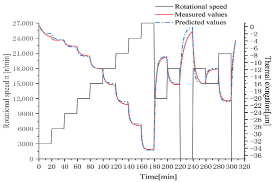
Figure 5.
Prediction model validation results.
The difference was calculated by subtracting the experimentally measured values from the model-predicted values, resulting in the residual plot of predicted values presented in Figure 6.
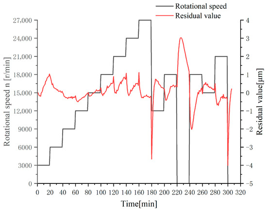
Figure 6.
Residual values of the prediction model.
From Figure 4 and Figure 5, it is observed that during the stepwise speed-increase phase (Stage I), the thermal elongation prediction model based on rotational speed and cumulative thermal error demonstrated good fitting performance with a maximum residual value of 1.03 μm and an average residual value of 0.31 μm. During the rapid speed-reduction phase (Stage II), although the overall prediction accuracy remained high when the spindle rotational speed stabilized, the residual value reached −3.66 μm during the first descent to 12,000 r/min and 3.03 μm during the second descent to shutdown state. In the rotational speed fluctuation phase (Stage III), residual values remained stable within −0.7 μm to 0.5 μm, but notably peaked at −4.01 μm at shutdown state. The prediction results of the cumulative thermal error model are presented in Table 3.
Table 3.
Prediction results of cumulative thermal error model.
The primary reason for the observed prediction errors during abrupt speed changes is the thermal inertia and heat transfer delay within the spindle system. When the rotational speed changes suddenly (e.g., a rapid decrease at t = 180 min or shutdown at t = 300 min), the heat generation rate in the bearings and motor changes almost instantaneously. However, the redistribution of this heat throughout the spindle’s mass and the resulting structural thermal deformation are governed by relatively slow thermal dynamics. Our current model, which primarily captures the dominant, slower thermal drift, effectively predicts the new steady-state but cannot instantly capture the very initial, rapid thermal transient as the system transitions between thermal states. There is an inherent time lag between the change in input (speed) and the full system response (elongation).
The transient prediction error of 3.66 μm, while relatively small, could indeed lead to visible machining artifacts in high-precision finishing operations, such as noticeable witness marks during ball-end milling of flat surfaces where toolpaths overlap. During detected speed transients, the compensation update cycle could be intelligently lengthened to effectively filter these short-term prediction peaks, prioritizing stability over instantaneous response.
Typically, the established spindle thermal elongation prediction model demonstrates satisfactory predictive performance under identical experimental conditions. However, when experimental conditions change, the prediction accuracy and robustness of the aforementioned model may become inadequate. Therefore, it is necessary to experimentally revalidate the established prediction model under altered operating conditions. To verify the universality of the proposed cumulative thermal error model for the motorized spindle under different operating conditions, test data acquired under random rotational speed conditions were designed for experimental validation.
An experiment with spindle rotational speed varying in the range of 3000–15,000–10,000 r/min was designed, with data collected at 1-min intervals. The measured spindle thermal elongation data and model validation results are presented in Figure 6. The prediction performance evaluation of the model is shown in Figure 7.
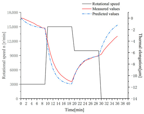
Figure 7.
Prediction model validation results under random speed.
In the validation experiments, the cumulative thermal error compensation model demonstrated satisfactory prediction performance, as shown in Figure 8. During the initial minutes after spindle start-up, the residual values exhibited significant fluctuations. After the rotational speed stabilized, the residuals converged to values around zero. During abrupt speed-increase transitions, a discrepancy of 1.28 μm was observed between predicted and experimentally measured values. The maximum residual value recorded during the experiments was 2.04 μm. The thermal compensation model established based on rotational speed and cumulative thermal error exhibits strong universality, being applicable to various variable-speed operating conditions while also delivering significant compensation effectiveness. During detected speed transients, the compensation update cycle could be intelligently lengthened to effectively filter these short-term prediction peaks, prioritizing stability over instantaneous response.
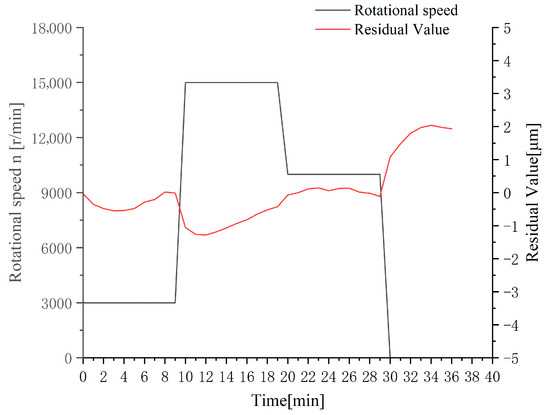
Figure 8.
Residual values of the prediction model under random speed.
The present study primarily targets high-precision machining centers, where the material removal rates are typically very low, and consequently, the cutting forces and the associated cutting heat are relatively small. In such applications, the primary and dominant source of thermal error is the internal heat generation from the spindle’s own components (such as bearings and the motor). Our experimental validation under no-load conditions effectively captures and models this primary heat source, which constitutes the most significant contribution to thermal elongation in high-precision scenarios. Cutting heat can significantly alter the thermal equilibrium. To address this, the additional thermal load from cutting could be treated as a disturbance input. A real-time compensation offset, potentially correlated with process parameters (e.g., spindle power or torque), could be added to the model’s output.
A more robust and effective long-term solution is to implement a direct closed-loop compensation system using a non-contact displacement sensor to measure the thermal elongation in real-time, thereby bypassing model prediction errors entirely.
6. Conclusions
The thermal elongation of machine tool spindles is influenced by multiple factors. This study selects rotational speed and cumulative thermal elongation as key state variables, proposes a novel thermal compensation model, establishes a parameter determination method, and validates the model through machine tool experiments. The main conclusions are as follows:
- (1)
- The cumulative thermal error compensation model parameters are determined through speed–thermal elongation experiments, where the speed profile comprehensively covers all practical spindle operating conditions, including start–stop, idle, stepwise speed changes, and rapid acceleration/deceleration. After compensation, the maximum residual error of the spindle under various speeds is controlled within 5 μm, with the average residual stabilized at approximately 1 μm.
- (2)
- Compared with conventional speed–time exponential models, the proposed model incorporates the historical thermal elongation state variable, which fundamentally resolves the prediction adaptability challenges during speed reduction and shutdown processes. This innovation increases modeling efficiency by 300% (single experiment vs. segmented modeling in traditional approaches).
- (3)
- Relative to multi-temperature variable models, the direct utilization of built-in encoder speed signals eliminates the need for temperature sensor installation, signal transmission systems, and multi-physics coupling modeling. This reduces implementation costs by 85% while maintaining equivalent compensation accuracy.
- (4)
- Validation under extreme operating conditions (staged acceleration, rapid deceleration, and emergency shutdown) confirms the model’s robust performance in untrained scenarios, with maximum residuals consistently below 5 μm. This demonstrates its universal applicability as an industrial-grade thermal error control solution.
If key parameters like geometric dimensions or material properties were to change significantly, the model parameters would require re-identification through a calibration process for the new spindle. These advancements provide a high-precision, low-cost technical pathway for thermal deformation control in precision machining systems.
Author Contributions
Writing—original draft preparation, X.L. and H.Y.; research design, L.J. and H.Y.; data analysis, X.L. and H.Y.; data collection, L.J. and X.L.; creation of charts, L.J. and X.L.; literature search, X.L. All authors have read and agreed to the published version of the manuscript.
Funding
This research was funded by the Jiangxi Science and Technology Plan Project, grant number [20244BAB28007].
Data Availability Statement
The raw data supporting the conclusions of this article will be made available by the authors on request.
Conflicts of Interest
The authors declare no conflict of interest.
References
- Wang, H.T.; Li, T.M.; Wang, L.P.; Li, F. Review on thermal error modeling of machine tools. J. Mech. Eng. 2015, 51, 119–128. [Google Scholar] [CrossRef]
- Yuan, J.L. Review on temperature field and thermal error of CNC machine tools. Enterp. Sci. Technol. Dev. 2025, 1, 106–110. [Google Scholar] [CrossRef]
- Yu, B.L. Research on Temperature Field Optimization and Thermal Error Modeling of High-Speed Electric Spindle. Master’s Thesis, Harbin University of Science and Technology, Harbin, China, 2024. [Google Scholar]
- Ding, Q.Q.; Guo, S.J.; Su, Z.; Zou, Y.; Tang, S. Temperature measuring point screening and thermal error prediction method for machine tool linear axis. Modul. Mach. Tool Autom. Manuf. Tech. 2024, 5, 22–27+32. [Google Scholar]
- Ma, S.; Leng, J.W.; Chen, Z.Y.; Li, W.; Li, B.; Liu, Q. Thermal error modeling method for electric spindle based on digital twin and deep transfer learning. J. Mech. Eng. 2025, 61, 52–66. [Google Scholar]
- Zhang, Y.; Yang, J.G. Neural network machine tool thermal error modeling based on grey theory preprocessing. J. Mech. Eng. 2011, 47, 134–139. [Google Scholar]
- Li, B.; Zhang, Y.; Wang, L.P.; Li, X. Thermal error modeling of CNC machine tools based on genetic algorithm optimized wavelet neural network. J. Mech. Eng. 2019, 55, 215–220. [Google Scholar]
- Zhou, J.Z.; Wang, R.H. Thermal error prediction modeling of high-speed electric spindle based on CPO-CNN-BiLSTM-Attention model. World Manuf. Eng. Mark. 2025, 1, 61–67. [Google Scholar]
- Wang, W.; Yang, J.G.; Yao, X.D.; Fan, K.; Li, Z. Comprehensive modeling and real-time compensation of geometric error and thermal error for CNC machine tools. J. Mech. Eng. 2012, 48, 165–170, 179. [Google Scholar] [CrossRef]
- Liao, L.; Liao, B.J.; Xie, Z. Research on thermal error modeling method of CNC machine tools based on GOA-BP neural network. J. Xi’an Aeronaut. Univ. 2025, 43, 52–59. [Google Scholar] [CrossRef]
- Lin, W.Q.; Fu, J.Z.; Xu, Y.Z.; Chen, Z.C. Thermal error modeling and compensation of CNC machine tools based on online least squares support vector machine. Comput. Integr. Manuf. Syst. 2008, 2, 295–299. [Google Scholar] [CrossRef]
- Zhou, M.J.; Yin, L.; Zhang, L.J.; Zhang, F.; Song, J.; Ye, Z. Research on thermal error modeling method of machine tool spindle based on optimized BP neural network. Mach. Tool Hydraul. 2024, 52, 136–142. [Google Scholar] [CrossRef]
- Zhang, X. Research on Automatic Measurement and Compensation Application Technology of Thermal Error for CNC Machine Tool Spindle. Master’s Thesis, Huazhong University of Science and Technology, Wuhan, China, 2024. [Google Scholar] [CrossRef]
- Wang, Q.F. Prediction and Compensation of Thermal Error for Vertical Machining Center Spindle. Master’s Thesis, Shandong University, Jinan, China, 2015. [Google Scholar]
- Dai, G.S.; Yuan, F.; Zhang, Y.S.; Yang, J. Thermal characteristics analysis and natural exponent-based thermal error modeling of electric spindle. Mach. Tool Hydraul. 2014, 42, 9–13. [Google Scholar]
- Zhang, Y.; Yang, J.G.; Li, Z.H. Machine tool positioning error modeling and real-time compensation based on natural exponent model. Modul. Mach. Tool Autom. Manuf. Tech. 2013, 8, 8–11+15. [Google Scholar]
- Fu, G.Q.; Gong, H.W.; Gao, H.L.; Gu, T.; Cao, Z. Integrated thermal error modeling of machine tool spindle using a chicken swarm optimization algorithm-based radial basic function neural network. Int. J. Adv. Manuf. Technol. 2019, 105, 2039–2055. [Google Scholar] [CrossRef]
- Rabréau, C.; Kekula, J.; Ritou, M.; Sulitka, M.; Shim, J.; Le Loch, S.; Furet, B. Influence of bearing kinematics hypotheses on ball bearing heat generation. In Proceedings of the 8th CIRP Conference on High Performance Cutting (HPC 2018), Budapest, Hungary, 25–27 June 2018; pp. 622–625. [Google Scholar] [CrossRef]
- Pandey, A.; Madduri, B.; Perng, C.Y.; Srinivasan, C.; Dhar, S. Multiphase flow and heat transfer in an electric motor. In Proceedings of the ASME 2022 International Mechanical Engineering Congress and Exposition, Columbus, OH, USA, 30 October–3 November 2022; p. 8. [Google Scholar]
- Yang, Z.; Liu, B.; Zhang, Y.; Chen, Y.; Zhao, H.; Zhang, G.; Yi, W.; Zhang, Z. Intelligent Sensing of Thermal Error of CNC Machine Tool Spindle Based on Multi-Source Information Fusion. Sensors 2024, 24, 3614. [Google Scholar] [CrossRef] [PubMed]
- Li, Z.K.; Liu, B.; Fransson, P.; Peretti, L. Equivalent resistance model of the permanent-magnet motor for predicting electromagnetic losses. In Proceedings of the 2024 International Conference on Electrical Machines (ICEM), Torino, Italy, 1–4 September 2024. [Google Scholar] [CrossRef]
- Zhuo, M.; Geng, J.Q.; Cui, Z.; Xia, K. A spindle compensation model based on rotational speed and cumulative thermal error. Modul. Mach. Tool Autom. Manuf. Tech. 2022, 9, 104–107. [Google Scholar] [CrossRef]
- Fu, G.; Mu, S.; Zheng, Y.; Lu, C.; Wang, X.; Wang, T. MA-CNN based spindle thermal error modeling using the depth feature analysis with thermal error mechanism. Measurement 2024, 226, 114183. [Google Scholar] [CrossRef]


Disclaimer/Publisher’s Note: The statements, opinions and data contained in all publications are solely those of the individual author(s) and contributor(s) and not of MDPI and/or the editor(s). MDPI and/or the editor(s) disclaim responsibility for any injury to people or property resulting from any ideas, methods, instructions or products referred to in the content. |
© 2025 by the authors. Licensee MDPI, Basel, Switzerland. This article is an open access article distributed under the terms and conditions of the Creative Commons Attribution (CC BY) license (https://creativecommons.org/licenses/by/4.0/).