Abstract
In the processes of deep hole drilling and boring, tool deflection and chatter are prevalent problems that significantly affect the quality and efficiency of deep hole part machining. This paper designs a Helical-Type Vibration-Damping and Deflection Correction Device for BTA (boring and trepanning association) deep hole drilling based on the principles of fluid dynamic pressure lubrication and squeeze film damping. By leveraging the flow field characteristics of cutting oil during machining, the device achieves vibration-damping, deflection correction, and enhanced support for the tool system throughout the drilling operation. Through theoretical analysis, this research examines the oil film pressure distribution and stability of the Designed Vibration-Damping and Deviation Correction Device. It also explores the influence patterns of factors such as cutting parameters, device structure, minimum film thickness, film thickness ratio, and length-to-diameter ratio on its vibration-damping, deviation correction, and stability performance. Taking a deep hole as the research object, an experimental platform was designed and constructed to measure and verify the device’s vibration-damping and deviation correction effects under different operating conditions. Deep hole drilling tests were carried out on 10 conventional gun steel specimens ( × 3000 ). The results indicate that, when the minimum oil film gap of the Vibration-Damping and Deflection Correction Device is 0.08, the axis deviation range is 0.27~0.45, with a surface roughness of 0.589 to 0.677. Compared to similar conditions without the device, these represent reductions of 55~73% and 47.07~53.95%, respectively. It allows for a reduction of over 10% in blank material allowance and an increase of 5–15% in tool feed rates.
1. Introduction
Wan et al. [1] discussed deep hole drilling technology, deep hole drilling technology originated from barrel machining and is now widely applied in the manufacturing of core components for military equipment, oil and gas extraction, and other machinery. Wang et al. [2] believe that during deep hole machining, the high depth-to-diameter ratio (typically exceeding 5) commonly leads to tool deflection and chatter in the tooling system (including both the cutting tool and tool holder). This results in suboptimal hole straightness and roundness precision. Furthermore, as mechanical products evolve and workpiece materials become increasingly complex, higher demands are placed on the machining accuracy, quality, and production efficiency of deep holes. Examples include deep hole drilling and boring in ultra-high-strength materials and zigzag deep hole machining in special materials. The prevalence of these challenges leads to elevated processing costs, significant resource consumption, and even the difficulty of machining certain deep hole components.
To address these issues, experts and scholars in relevant fields have conducted in-depth research.
Richardson et al. [3,4] reviewed the role of guide strips in BTA deep hole drilling tools during machining, analyzing the influence of factors such as cutting speed, feed rate, and guide strip squeeze finishing on the surface roughness of deep holes. Li et al. [5,6,7,8] established the variation patterns of contact angle, contact stress, and extrusion deformation between BTA drill guide strips and hole walls during drilling using elastoplastic deformation theory and Hertzian contact theory. Afzaal et al. [9,10,11,12] investigated the motion characteristics of micron-sized chips during electrical discharge machining (EDM) via CFD simulation, proposing that chip trajectories correlate with chip size. Robert et al. [13,14,15] proposed integrating a sensor system beneath the guide key of BTA drills to capture machining parameters and comprehensive hole wall surface information. Frederic et al. [16,17,18] designed a deviation compensation device between the drill and drill rod, employing ultrasonic monitoring for hole wall thickness; Kong et al. [19,20] investigated the nonlinear dynamics of tool systems and the unsteady hydrodynamic characteristics of cutting fluid between drill rods and borehole walls during deep hole drilling. They elucidated the influence of drill rod motion parameters and structural design on cutting fluid forces, as well as the mechanisms affecting drill rod vortex formation and instability. Robert et al. [21] investigated the influence of cutting speed, feed rate, and factors such as wall-induced pressure and cutting forces on the subsurface characteristics of AISI 4140 and AISI 304 L ultra-high-strength materials during deep hole drilling. Their findings provide a basis for optimizing machining processes to control part fatigue strength and reliability.
In conclusion, the existing research on improving the quality and efficiency of deep hole machining has mainly concentrated on the optimization of process parameters and equipment, the integration of ultrasonic vibration assistance, the application of specialized machining techniques, and the implementation of real-time monitoring and control. Nevertheless, research on comprehensively leveraging the flow characteristics of cutting fluids to achieve vibration-damping and tool deflection correction within deep hole tooling systems has yet to be conducted.
Taking into account vibration-damping and deflection correction for deep hole cutting tools is crucial for addressing such problems. In contrast to the previously mentioned research results, this paper innovatively puts forward a design theory for a Helical-Type Vibration-Damping and Deflection Correction Device based on dynamic pressure lubrication theory and the principle of squeeze film damping. By making use of the cutting oil present in deep hole machining, the device is designed on the basis of the existing common process equipment. It is characterized by a simple structure, convenient operation, strong adaptability, and remarkable efficacy, thus overcoming the problem of poor hole straightness faced by current deep hole drilling equipment when machining difficult-to-cut materials. Moreover, this paper expounds on the Vibration-Damping and Deflection Correction mechanism of the device, uncovering the factors and patterns influencing the tool oil film pressure distribution and stability during deep hole machining. Through a rational structural design of the Vibration-Damping and Deflection Correction Device, effective vibration-damping and deflection correction of the tool system during machining are achieved.
2. Theory of Vibration-Damping and Deviation Correction for BTA Deep Hole Drilling Tool Systems
2.1. Vibration-Damping and Deviation Correction Mechanism
The BTA system is among the most frequently employed deep hole machining systems. Its operational principle is as follows: during the process of deep hole drilling, the workpiece rotates at a speed of while the tool system rotates at a speed of , thereby generating relative rotational motion. Concurrently, pressurized cutting oil enters through the oil feeder into the annular space between the outer wall of the drill rod and the machined surface of the workpiece. This oil reaches the tool head for the purposes of cooling and lubrication, and it expels chips through the interior of the drill rod [2], as depicted in Figure 1a. Building upon this system, this paper integrates the theory of fluid dynamic pressure lubrication with the principle of extrusion film damping. By taking into account the flow characteristics of cutting oil and boundary layer theory, a Helical-Type Vibration-Damping and Deflection Correction Device was designed to connect the drill head and shank. Its structure, installation location, and operating principle are illustrated in Figure 1.
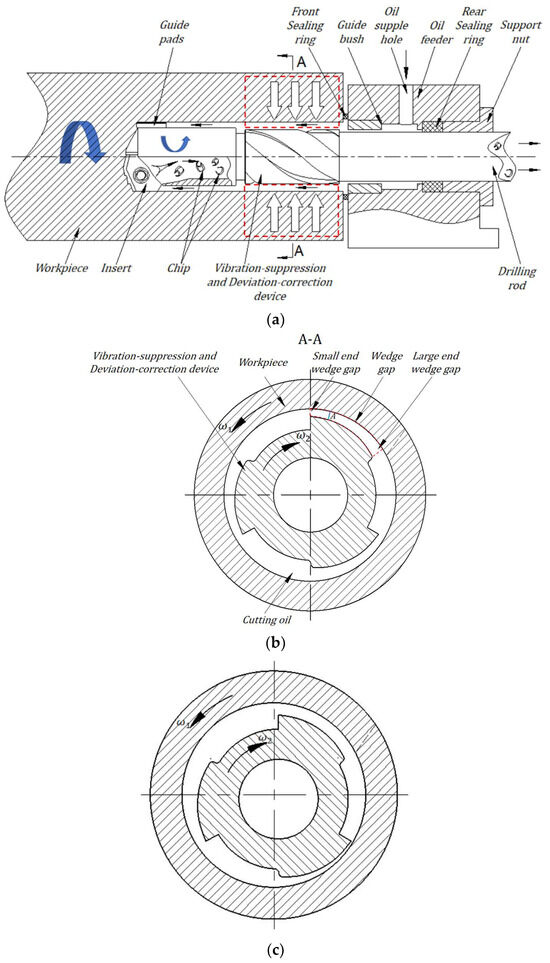
Figure 1.
(a). Schematic diagram of the Vibration-Damping and Deviation Correction Deep Hole Drilling Tool System. (b). Schematic cross-section of the device at the ideal position of the tooling system. (c). Schematic cross-section of the device during tool system flutter eccentricity.
Figure 1b shows the wedge-shaped gap filled with cutting oil. Owing to the viscosity of the oil and the narrowness of the gap, the oil within the boundary layer adsorbed on the surface of the bore wall rotates counterclockwise along with the workpiece, moving from the larger end to the smaller end of the wedge gap. Yu et al. [22] believe that once the conditions for forming a dynamic pressure oil film are met, the oil film will generate dynamic pressure. When the tool system rotates clockwise, the viscous forces of the cutting oil in the external flow region of the boundary layer are significantly smaller than the inertial forces. Furthermore, the gap at any cross-section A of the wedge-shaped oil film decreases as the tool system rotates, causing the oil film to be compressed and generate a reaction force. This results in oil film compression pressure. The combined dynamic pressure and compression pressure of the oil film provide support and positioning for the tool system located at the hole center. When the tool system deviates from the hole center due to cutting forces and undergoes displacement motion near the hole center, as illustrated in Figure 1c (i.e., tool chatter occurs), two phenomena occur: First, the wedge-shaped gap oil film forms oil film damping due to compression or stretching. This damping dissipates the tool system’s vibrational energy and prevents oil film rupture, creating an oil film damping force that suppresses tool vibration. Second, the oil film in the wedge-shaped gap thins under compression, generating relatively greater dynamic pressure, while thickening under tension produces relatively smaller dynamic pressure or negative pressure. This forces the tool system to deviate from the hole center back toward the hole center position.
2.2. Theoretical Analysis of Oil Film Pressure Distribution in Devices
2.2.1. Thickness of the Wedge-Shaped Oil Film in the Device
To investigate the pressure distribution of the wedge-shaped oil film in the apparatus, it is first necessary to derive an expression for the oil film thickness h. Given that the three wedge–shaped protrusions of the device are configured with a uniform circumferential distribution, and their cross-sectional curves adhere to an Archimedean spiral, we analyze one protrusion, as shown in Figure 2. Here, is the rotational center of the bore and device, is the lowest point of the wedge protrusion, is its polar radius, and is the oil film thickness at this point. is the highest point of the wedge protrusion, is its polar radius, and is the oil film thickness at this point; denotes the deep hole radius. Selecting any point on the wedge surface with a rotation angle θ, the oil film thickness at point is as follows:
where .
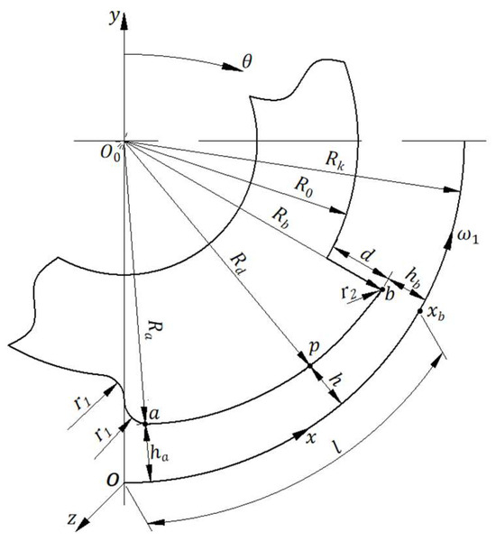
Figure 2.
Positioning relationship between the surface of a single wedge-shaped projection and the hole wall.
2.2.2. Analysis and Calculation of Pressure Distribution Within Wedge-Shaped Oil Film for Device
The wedge-shaped gap formed between the wedge-shaped protrusion surface of the device and the bore wall of the workpiece is filled with cutting oil. As the workpiece rotates at an angular velocity , the flow of cutting oil adhering to its bore wall resembles the flow within a boundary layer. Based on boundary layer theory, a rotating coordinate system is established, as shown in Figure 2. The -axis is normal to the inner hole surface and points toward the center of the workpiece’s inner hole. The -axis aligns with the axis of the inner hole, while the -axis is the axis of rotation, coinciding with the cross-sectional circle of the workpiece’s bore, pointing counterclockwise, i.e., as follows:
Therefore,
where .
The hole wall moves at a constant speed,
along the -axis. The pressures at both ends, and , are taken as constant values, , and the oil film thickness is defined as . The arc length of the hole cross-section corresponding to the cross-section of the wedge-shaped protrusion is calculated as follows:
Since the oil film thickness is on the micrometer scale, it is much smaller than , i.e., we obtain the following:
which is a small amount.
Let the flow velocity of the cutting oil within the gap be represented by the vector . Referring to the boundary layer problem, estimate the order of magnitude of , , using ε as the estimation criterion.
Introduce the following dimensionless quantities:
where is pressure, is density, and and are the scalar components of velocity in a two-dimensional coordinate system. is the characteristic velocity, is the characteristic length, and is the characteristic time.
Clearly, within the boundary layer, and are of the same order of magnitude. Therefore, is of the same order of magnitude as 1. Let the following be true:
Secondly, as varies from 0 to ε, varies from 0 to a quantity of the same order as 1. Therefore, the order of is , i.e., we obtain the following:
Similarly, the following can be proved:
When moves from point to a quantity of the same order as 1, changes by a quantity of the same order as 1; therefore, the following is true:
Similarly, the following can be proved:
From Equations (11) and (13), we obtain the following:
Pressure gradient is a passive force, typically serving a regulatory function. The order of magnitude of , is determined by the largest order of magnitude among the inertial forces and viscous forces. The inertial forces and viscous forces are of the same order; therefore, the orders of magnitude of and are, respectively, as follows:
The gradient of pressure along the normal direction , , is one order lower than the gradient along the -direction of the pore wall, . Compared to , within the first-order approximation range, .
Converting Equations (15) and (16) to their dimensionless forms yields the following:
The pressure value does not change in the direction perpendicular to the boundary layer,.
Based on the above analysis, the system of equations for the planar steady-state motion of cutting oil in the wedge zone is derived:
This can be simplified as follows:
An order-of-magnitude estimate is now provided for the ratio of inertial forces to viscous forces:
where , , denotes the kinematic viscosity of the cutting oil.
The current drilling data for a mm deep hole is as follows:
Workpiece rotational speed , tool speed , ,,, , and .
After calculation, it is found that , , and . It can be seen that the inertial forces are smaller than the viscous forces. Therefore, the equation of motion in (20) can be written as follows:
The continuity Equation (19) can be replaced by the condition that the flow rate is constant across all cross-sections.
The boundary conditions are the following:
Since is a function of , integrating Equation (22) twice and considering boundary condition (24) yields the following:
Using Equation (23) and boundary condition (25) to determine , substituting Equation (26) into (23) yields the following:
Namely,
Let at be denoted by ; then, we obtain the following:
Substituting Equation (29) into Equation (28) and considering Equation (3), let the following be true:
where . Then, we obtain the following:
We then obtain the following:
The integral is obtained as follows:
where
Substituting boundary condition (25) into the above equation determines the integration constants and , yielding the following:
Substituting into (34) yields the following:
According to Newton’s law of internal friction, the viscous shear stress on the inner bore wall is as follows:
Using Equation (39) in conjunction with Equations (32) and (35), the resultant pressure on the hole wall section corresponding to the wedge-shaped protrusion section can be calculated as follows:
where
Equation (40) represents the mathematical model for oil film pressure, with its numerical simulation analysis shown in Figure 3, and the meanings of variable symbols in the figure are shown in Table 1.
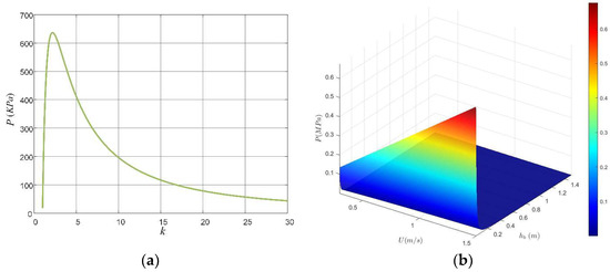
Figure 3.
The numerical simulation analysis of the mathematical model of the oil film pressure of the device. (a) - relationship curve. (b) -- relationship surface.

Table 1.
Variable Symbol Meaning Reference Table.
Based on Equation (39), the resultant viscous force acting on the bore wall cross-section corresponding to the wedge-shaped protrusion cross-section is calculated as follows:
From Equation (40), it can be seen that the value of the combined pressure depends on the magnitude of . When and , . Within this interval, there exists an extreme value of . Now, we find the derivative of with respect to :
Thus, the transcendental equation satisfied by when attains its extreme value is obtained as follows:
The approximate numerical solution sought is as follows:
At this point, reaches its maximum value.
In the above-mentioned theoretical calculations, it is postulated that the workpiece and tool system experiences two-dimensional motion, and that the oil film pressure does not decrease in the z-direction. Moreover, the calculations presume that the oil viscosity coefficient is invariant and that the oil is incompressible.
2.3. Key Dimension Design for Vibration-Damping and Deflection Correction Device in Deep Hole Drilling
2.3.1. Helix Angle
As shown in Equation (41), the greater the velocity of the cutting oil from the larger gap end to the smaller gap end, the larger the oil film force generated. However, the rotational speed of the workpiece and tool system, which governs this velocity, is constrained by process limitations. When cutting oil enters the gap between the Vibration-Damping and Deflection Correction Device and the workpiece bore under pump pressure, it possesses a certain velocity and pressure. Its direction of velocity, , points along the workpiece bore axis toward the tool, as shown in Figure 4. Simultaneously, the rotation of the workpiece bore wall induces the cutting oil to rotate around the axis, generating a rotational velocity . The resultant velocity combining and is . When the direction is perpendicular and points toward the axial helix of the device’s wedge-shaped protrusion, a greater oil film force can be generated. Therefore, it is preferable that the tangent value of the helix angle of the axial helix satisfies the following condition:
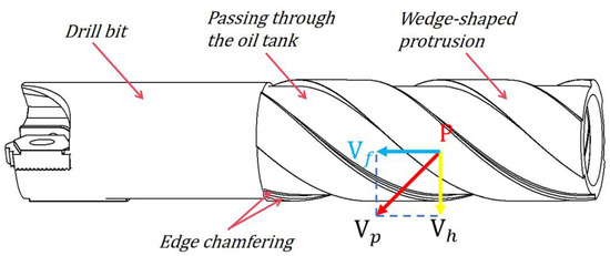
Figure 4.
Vibration-Damping and Deflection Correction Device and tooling.
Among these, is typically set between 10° and 15°. Compared to linear wedge protrusion designs, the right-handed helical wedge protrusion structure offers two key advantages: First, it exhibits a superior deviation correction capability, with cutting oil flowing from the larger end to the smaller end of the wedge gap at a relative velocity approaching its maximum value while maintaining a uniform flow rate, thereby generating the maximum and most stable theoretical oil film force. Second, it exhibits a superior operational stability. Due to its circumferential force distribution, it partially compensates for uneven oil film forces caused by manufacturing and installation coaxiality errors, thereby reducing their impact on the tooling system. Third, the device exhibits an extended service life. Its longevity is determined by wear rate, and the helical structure effectively prevents failure due to friction wear caused by severe tool chatter where a wedge protrusion edge rubs against the workpiece inner wall.
2.3.2. Minimum Oil Film Thickness
The radial clearance between the outer surface of the Vibration-Damping and Deflection Correction Device and the bore wall affects the oil film pressure and motion stability of the device. Based on the aforementioned theoretical analysis, under constant conditions, the smaller the minimum oil film thickness on the wedge surface of the Vibration-Damping and Deflection Correction Device, the greater its load-bearing capacity. However, the minimum oil film thickness cannot be infinitely small in practical applications due to constraints such as the roughness of the borehole inner wall and the wedge surface of the device, the rigidity of the device and tool holder, geometric errors in deep holes caused by tool wear, and installation errors of the device. To ensure the device operates under liquid friction conditions, the minimum oil film thickness must be equal to or greater than the allowable oil film thickness , i.e., the following must be true:
In the formula, and represent the arithmetic mean deviations of the inner wall profile and the wedge surface profile of the device, respectively. For conventional deep hole drilling of gun steel, and can be set to 3.2 and 1, respectively.
denotes the radial wear of the drill bit, with values ranging 10~20 in the conventional deep hole drilling of gun steel.
represents the installation error of the device. For the conventional deep hole drilling of gun steel, this is set to 20.
represents the safety factor, accounting for surface geometric errors, deflection of the device and tool holder, etc. Generally, is adopted.
2.3.3. Film Thickness Ratio
The film thickness ratio refers to the ratio of the oil film thickness at point of the wedge to the oil film thickness at point , which influences the magnitude of the resulting oil film pressure. As shown in Equation (41), once the drilling parameters are fixed, the viscous force depends on and , where is a constant. When or , . Since the minimum oil film thickness is constrained by permissible conditions, there exists a specific value of within this range that yields the extreme value of . Its numerical solution is as follows:
2.3.4. Oil Passage Groove
To ensure that a sufficient flow of cutting oil reaches the cutting edge during drilling operations and prevents the installation of the Vibration-Damping and Deflection Correction Device from compromising the oil’s cooling, lubrication, and chip-flushing functions, an oil channel has been designed, as shown in Figure 3. The radius of the device’s cylindrical base must satisfy the following conditions:
where the coefficient ranges from 1.1 to 1.5, while ranges from 0.9 to 0.93.
As shown in Figure 2, let the depth of the oil passage groove be . We then obtain the following:
2.3.5. Edge Chamfering
The lower end point of the wedge-shaped protrusion is designed with a fillet or streamlined profile at both the edge and its intersection with the base cylinder, as shown in Figure 3. Therefore, the fillet radii at these two locations in Figure 2 are as follows:
The purpose of this design is twofold: first, to reduce resistance to cutting oil flow toward the narrow end of the gap; second, to prevent vortex formation at the oil groove and the step at the low end of the wedge-shaped protrusion during device rotation, thereby minimizing kinetic energy loss. The high end of the wedge-shaped protrusion features a rounded edge with a radius to prevent the tool system from scratching the inner wall of the guide sleeve or the bore wall of the workpiece during severe vibrations.
2.3.6. Aspect Ratio
The length-to-diameter ratio refers to the ratio of the axial length of the wedge structure in the Vibration-Damping and Deflection Correction Device to the diameter of the processed hole, i.e., . When selecting the length-to-diameter ratio, the average oil film pressure of the device must be considered:
The value of should be set higher to enhance the stability of the device operation and reduce its overall dimensions. For standard gun steel deep hole drilling workpieces, considering factors such as machining process parameters, device machining and installation errors, and the structure of the machine tool oil feeder, the value of the Vibration-Damping and Deflection Correction Device is 1.67~2.67.
3. Experimental Analysis
3.1. Laboratory Bench Design and Construction
This experiment aims to determine the effects of factors such as the wedge structure and rotational speed on oil film pressure. The machine tool used was a WB CNC deep hole drilling and boring machine. A Botek drill bit was employed, with a drill rod. The cutting oil used (deep hole drilling oil) has a kinematic viscosity of 18~22 mm2/S at room temperature. Since the cutting oil supplied during the rotation of the Vibration-Damping and Deflection Correction Device is pumped from the oil reservoir, its temperature is maintained between 25 °C and 30 °C, allowing its oil properties to be considered unchanged. The experiment workpiece material was 45 steel (× 2500). Eight different specifications of the Vibration-Damping and Deflection Correction Device were tested: ST29.35-0.1-0.22-10, ST29.35-0.08-0.175-15, ST29.35-0.08-0.175-10, ST29.35-0.03-0.066-10, ST29.35-0.03-0.066-10, LT29.35-0.1-0.22-0, LT29.35-0.08-0.175-0, and LT29.35-0.03-0.1-0. The model format meaning was as follows: A-B-C-D, A—Device structure (ST29.35: drill bit with helical device; LT29.35: drill bit with straight-type device), B—minimum wedge oil film thickness, C—maximum wedge oil film thickness, and D—helix angle. A physical diagram of the device is shown in Figure 5.
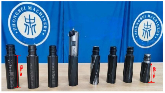
Figure 5.
Actual images of Vibration-Damping and Deflection Correction Device with different specifications and structures.
Using the ST29.35-0.08-0.175-15 Vibration-Damping and Deflection Correction Device Tool System (including drill bit, Vibration-Damping and Deflection Correction Device, and tool shank), drill a 350 mm deep hole in the workpiece. Then, machine drainage installation holes at 170 mm and 340 mm from the workpiece end face, as shown in Figure 6 and Figure 7. The upper end serves as the mounting position for the M5 pressure sensor probe, while the lower end features a 2 mm drainage hole. This hole directs pressure oil from the wedge gap to the sensing end of the pressure sensor probe, enabling the measurement of the oil film pressure within the Vibration-Damping and Deflection Correction Device. The pressure sensor employs a miniature dynamic liquid pressure transmitter with a measurement range of 0 to 1 MPa and a measurement accuracy of ±0.5% of full scale.
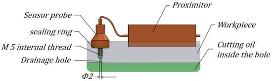
Figure 6.
Schematic diagram of workpiece drainage positioning holes and pressure sensor installation.
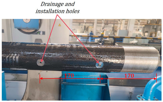
Figure 7.
Actual view of workpiece drainage holes and sensor mounting holes.
The slip ring is installed at the workpiece port, as shown in Figure 8. Its inner ring rotates with the workpiece, while the outer ring remains relatively stationary via a lever, enabling the transmission of oil film pressure voltage signals. The eddy current displacement sensor bracket is secured to a support mount positioned 0.9 m from the machine tool feeder’s oil seal. The eddy current displacement sensor is then installed, as shown in Figure 9, to measure the - and -axis displacement of the drill pipe at this location; the sensor has a measurement accuracy of 0.001 mm and is calibrated using 42CrMo alloy steel (drill pipe material) prior to shipment. Sensor signals are acquired via a dynamic signal testing and analysis system, and the sampling frequency is set to 12.8 kHz, as illustrated in Figure 10.
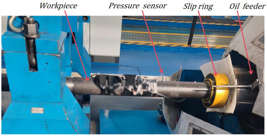
Figure 8.
Actual installation diagram of pressure sensor and slip ring.
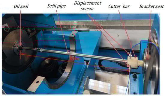
Figure 9.
Eddy current sensor installation diagram.
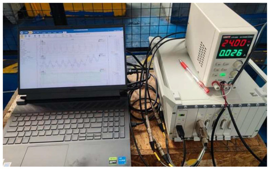
Figure 10.
Sensor data acquisition system.
3.2. Measurement and Analysis of Oil Film Pressure Distribution and Stability
For the aforementioned test bench, the Vibration-Damping and Deflection Correction Tool System was first inserted into the workpiece’s internal bore. By setting different test conditions, experiments were conducted on eight device samples to obtain their oil film pressure distribution and drill rod vibration displacement data under varying conditions. Partial data for the ST29.35-0.08-0.175-15 Vibration-Damping and Deflection Correction Device is shown below. The first row in Figure 11a depicts the oil film pressure waveform diagram, analyzing the oil film pressure distribution. The second row shows the horizontal () displacement waveform at the drill pipe measurement point, while the third row displays the vertical () displacement waveform at the same point. Figure 11b shows the approximate circular radius of the axis movement trajectory at the continuous measurement points obtained after processing the x-y data., which is used to analyze the stability of the device’s operation.
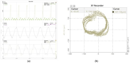
Figure 11.
Oil film pressure distribution and drill pipe vibration displacement test data. (a) Oil film pressure distribution and drill rod vibration at tool system speed of 490 ; (b) Movement trajectory of the drill pipe axis at the measuring point during the feed process of the tooling system.
3.2.1. The Influence of Structure on the Distribution and Stability of Oil Film Pressure in the Device
Under the cutting parameters of workpiece speed 100 r/min, tool system speed 490 , and feed rate 40 , the oil film pressure distribution and stability of the ST29.35-0.08-0.175-15, ST29.35-0.08-0.175-10, and LT29.35-0.08-0.175-0 devices were measured. Utilizing the data processing capabilities of the dynamic signal testing and analysis system, the oil film pressure and average oil film pressure range at the measurement point were obtained by statistically summarizing 5000 peak values and calculating the radius of the centerline trajectory circle, as shown in Table 2 and Figure 12 below.
Table 2.
Data processing results for oil film pressure and axis trajectory circle radius at the measurement point.
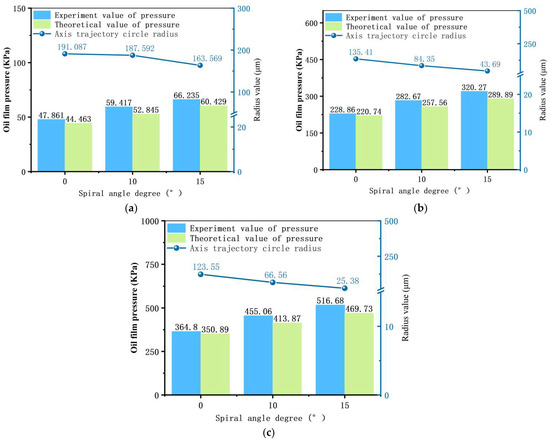
Figure 12.
Effect of wedge helix angle on oil film pressure and stability at different rotational speeds. (a) Workpiece rotational speed 90 ; (b) tool system rotational speed 490 r/min; (c) workpiece–tool speed 100–490 r/min.
As shown in Figure 12, the oil film pressure generated by the device increases with the increase in its wedge helix angle; the radius of the axis movement trajectory decreases with the increase in the helix angle. This experiment demonstrates that designing the device’s wedge protrusion as a helical structure can increase oil film pressure by 40% and improve operational stability by nearly sixfold. However, the helix angle should not be excessively large, as this would impair the chip-breaking function of the cutting oil.
3.2.2. The Effect of Minimum Oil Film Thickness on the Oil Film Pressure Distribution and Stability of the Equipment
By replacing the drill bit guide key to alter the diameter of the workpiece’s deep hole, the minimum wedge oil film thickness of the device is indirectly modified. The oil film pressure distribution under different minimum wedge oil film thicknesses is measured. The following figures show the average oil film pressure and stability of the ST29.35-0.08-0.175-15 vibration-damping and alignment device under the following conditions: workpiece speed of 90 mm/min, Vibration-Damping and Deflection Correction Tool System speed of 490 r/min, and workpiece–tool system speed of 100–490 r/min. Process the collected data, the results are shown in Table 3.
Table 3.
Data processing results for oil film pressure and axis trajectory circle radius at the measurement point.
As shown in Figure 13, the oil film pressure increases as the minimum oil film thickness decreases, with the rate of increase gradually slowing down. Within the 0.005–0.1 range, the radius of the shaft center’s motion trajectory remains largely stable, exhibiting a fluctuating pattern. This experiment demonstrates that, the smaller the wedge-shaped device’s minimum oil film thickness, the greater the generated oil film pressure; however, the more severe the wear on the device’s wedge surface, the more likely it is to scratch the workpiece’s inner bore surface and induce chatter in the tool system. When the minimum oil film thickness is 0.08–0.1, a relatively high oil film pressure can be generated without wear observed on the device’s wedge surface, and the radius of the shaft center’s trajectory is small. When the minimum oil film thickness exceeds 0.3, the oil film pressure becomes very low, and the oil film fails to form effectively. This experiment verifies that, when the tool system deviates or vibrates during drilling, the side with the thinner oil film experiences higher oil pressure, while the side with the thicker oil film has lower pressure. This pressure difference guides the tool system back to the hole center, achieving correction and vibration-damping.
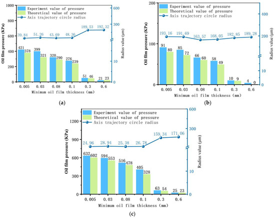
Figure 13.
Effect of minimum oil film thickness on oil film pressure and stability at different rotational speeds. (a) Workpiece rotational speed 90 ; (b) tool system rotational speed 490 ; (c) workpiece–tool speed 100–490 .
3.2.3. Effect of Rotational Speed on Oil Film Pressure Distribution and Stability in the Device
The ST29.35-0.08-0.175-15 Vibration-Damping and Deflection Correction Device is selected for analysis, featuring a minimum oil film thickness of 0.08 and a feed rate of 40 . The settings are as follows:
- (1)
- Tool system stationary; workpiece rotation at 40 , 70 , 90 , 125 , and 140
- (2)
- Workpiece stationary; tool system rotation at 190 , 290 , 390 , 490 , and 590
- (3)
- Both workpiece and tool system rotating: 40–290 , 90–490 , 177–413 , 100–490 , 100–520 , and 125–590 . The average values of oil film pressure and the radius of the shaft center’s trajectory are recorded, as shown in Figure 14.
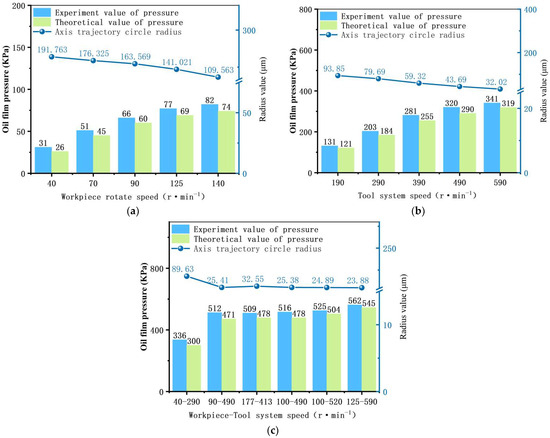 Figure 14. Effect of rotational speed on oil film pressure and stability. (a) Workpiece rotation; (b) tooling system rotation; (c) workpiece–tool relative rotation.
Process the collected data, the results are shown in Table 4.
Table 4.
Data processing results for oil film pressure and axis trajectory circle radius at the measurement point.
As shown in Figure 14a,b, the oil film pressure increases with rising workpiece rotational speed and Vibration-Damping and Deflection Correction Tool System speed, though the rate of increase gradually diminishes. The radius of the axial motion trajectory decreases with increasing rotational speed and stabilizes. Figure 13c indicates that the rotational speed ratio between the workpiece and Vibration-Damping and Deflection Correction Tool System has a negligible effect on the magnitude of the generated oil film pressure. The experiments demonstrate that, at a workpiece–tool system speed of 100–490, a relatively stable oil film pressure of 516 can be formed with satisfactory stability, verifying the device’s supporting and vibration-damping effect during the drilling process.
3.3. ϕ29.35 Deep Hole Drilling Test
Based on the aforementioned experimental analysis, a ST29.35-0.08-0.175-15 Vibration-Damping and Deflection Correction Device was selected for deep hole drilling tests on a 3 m long ordinary gun steel workpiece. The drilling test apparatus is shown in Figure 15. A sample size of 10 pieces was used. Partial workpieces after deep hole drilling, as shown in Figure 16. The deviation at the exit of the drilled hole was measured indirectly by determining the maximum and minimum runout values at the hole exit. The deviation was calculated using the following formula:
where is the deviation amount at the deep hole exit, is the maximum runout at the exit, and is the minimum runout at the exit, with each of the 10 samples tested three times and the average value calculated. The surface roughness of the drilled hole was measured using a roughness tester.
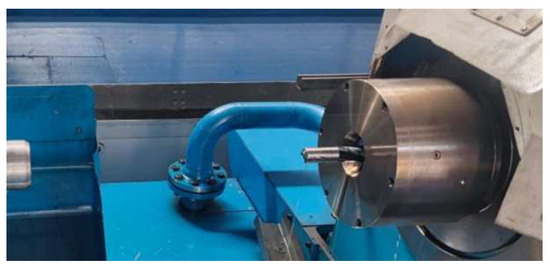
Figure 15.
Vibration-Damping and Deflection Correction Tool System for drilling ordinary gun steel.
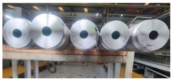
Figure 16.
Partially machined workpieces using the Vibration-Damping and Deflection Correction Tool System.
Testing revealed that, when drilling 3 m ordinary gun steel workpieces using the ST29.35-0.08-0.175-15 Vibration-Damping and Deflection Correction Tool System, the axial deviation ranged from 0.27 to 0.45, with a surface roughness of 0.589~0.677 . The machining quality of this machine tool for drilling workpieces of the same specifications in recent years is as follows: the average exit deviation is 1 , and the average surface roughness is 1.279 . These data were provided by the production department of the partner enterprise. The deviation at the deep hole outlet decreased by 55% to 73%, while the surface roughness decreased by 47.07% to 53.95%.
4. Conclusions
- A novel vibration-damping and deflection correction method for deep hole machining based on dynamic pressure lubrication and squeeze film damping theory is proposed, with a detailed elaboration on its operational principles. A Vibration-Damping and Deflection Correction Device for BTA deep hole drilling is designed. This device generates oil film pressure during drilling, exerting vibration-damping and deviation correction effects on the tool system. Consequently, it reduces exit deviation in deep hole machining and suppresses chatter.
- Through theoretical analysis and experimental validation of the Vibration-Damping and Deflection Correction Device, the influence patterns of structural dimensions, minimum oil film thickness, rotational speed, and other factors on oil film pressure distribution and stability were established. Design criteria for the key dimensions of the Vibration-Damping and Deflection Correction Device were derived. Experimental validation: The calculated results from the constructed oil film pressure mathematical model exhibit consistent trends with the experimental measurements. The numerical deviation between the two falls within ±15%. Beyond considering sensor measurement accuracy, the underlying causes warrant further investigation. Research indicates that, when drilling ordinary gun steel workpieces, designing the device with a minimum oil film thickness of 0.08 a helix angle of 15°, and a length of 50 can form a large and stable oil film, achieving the device’s vibration-damping and deviation correction performance.
- This vibration-damping and deviation correction theory has been applied in drilling , , and deep holes, such as and . The axial deviation of deep holes after drilling was reduced by an average of 50% to 70%, while the roundness error decreased by an average of 28%. The axial deviation of deep holes after boring was reduced by an average of 25% to 50%, while the roundness error decreased by an average of 15%. The roundness error is directly related to the amplitude of the tool system vibration. Therefore, research on the dynamic characteristics (stiffness coefficient and damping coefficient) of the wedge-shaped pressure oil film, both through calculation and experimental determination, is of great significance for the optimized design of this device.
- To facilitate inspection of the Vibration-Damping and Deflection Correction Device’s machining quality, the device can be designed with four wedge-shaped protrusions evenly distributed around the circumference—a structure symmetrical about the axis origin. The wedge dimensions can be directly measured using a tilt meter and micrometer.
Author Contributions
Conceptualization, Y.W. and D.Y.; methodology, Y.W.; software, Y.W.; validation, Y.W., T.C. and D.Y.; formal analysis, Y.W.; investigation, Y.W., T.C., and D.Y.; resources, Y.W.; data curation, Y.W.; writing—original draft preparation, Y.W.; writing—review and editing, D.Y.; visualization, Y.W.; supervision, D.Y.; project administration, D.Y.; funding acquisition, D.Y. All authors have read and agreed to the published version of the manuscript.
Funding
This work was supported by the following grants: National Natural Science Foundation of China (Grant No. 51875532); Central Guidance for Local Scientific and Technological Development (Grant No. YDZJSX2022C006); ***Technology Transfer Application Project (Grant No. ***020402); ***Technology Transfer Application Project (Grant No. ***A7597).
Data Availability Statement
Data are contained within this article.
Conflicts of Interest
The authors declare that they have no known competing financial interests or personal relationships that could have appeared to influence the work reported in this paper.
References
- Wan, B.Y.; Peng, F.; Jin, Y.; Peng, Y.; Liu, D. Drilling Technology Status and Development Trends of Deep-sea Seafloor Drill. J. Mech. Eng. 2024, 60, 385–402. [Google Scholar]
- Wang, S.Q. Deep Hole Machining Technology, 3rd ed.; Northwestern Polytechnical University Press: Xi’an, China, 2003; pp. 1–10. [Google Scholar]
- Chandar, J.B.; Nagarajan, L.; Kumar, M.S. Recent Research Progress in Deep Hole Drilling Process: A Review. Surf. Rev. Lett. 2021, 28, 213003. [Google Scholar] [CrossRef]
- Richardson, R.; Bhatti, R. A review of research into the role of guide pads in BTA deep-hole machining. J. Mater. Process. Technol. 2001, 110, 61–69. [Google Scholar] [CrossRef]
- Li, X.; Zheng, J.; Yu, B.; Du, Y.; Zhou, Y. Analytical Model of Hole Diameter and Self-Guiding Machining Mechanism of BTA Deep Hole Drilling. Materials 2022, 15, 5329. [Google Scholar] [CrossRef] [PubMed]
- Zhang, R.; Liang, Z.; Yi, L.; Hu, J.; Du, Y.; Ma, Y.; Zhao, Q.; Xiong, L.; Zhao, Y. Research on the mechanism of single-tooth BTA deep hole processing under the condition of a weakly rigid slender drill rod. Eng. Fail. Anal. 2025, 170, 109302. [Google Scholar] [CrossRef]
- Summa, J.; Michel, S.; Kurkowski, M.; Biermann, D.; Stommel, M.; Herrmann, H.-G. Process Monitoring of a Vibration Dampening CFRP Drill Tube in BTA deep hole drilling using Fibre-Bragg-Grating Sensors. Procedia CIRP 2022, 115, 119–124. [Google Scholar] [CrossRef]
- Atsutoshi, H.; Hiromitsu, G.; Takayuki, T. Effect of Electrode Shape on High Aspect Ratio Deep Hole Drilling by EDM. Procedia CIRP 2022, 113, 262–266. [Google Scholar] [CrossRef]
- Afzaal, A.; Jibin, B.; Mustafizur, R. Novel EDM deep hole drilling strategy using tubular electrode with orifice. CIRP Ann. Manuf. Technol. 2021, 70, 151–154. [Google Scholar]
- Wang, P.; Hu, J.; Hu, H.; Yu, D.; Yin, Z.; Zou, H.; Lai, T. Debris motion and taper suppression in EDM deep hole machining assisted by longitudinal/torsional ultrasonic vibration. J. Manuf. Process. 2025, 133, 798–810. [Google Scholar] [CrossRef]
- Jibin, B.; Afzaal, A.; Ashwani, A. Effect of recirculation zone on debris evacuation during EDM deep hole drilling. Procedia CIRP 2021, 102, 393–398. [Google Scholar] [CrossRef]
- Fan, R.; Mei, X.; Cui, J. Process in laser drilling of deep microholes without taper on metal materials. Sci. China Technol. Sci. 2024, 67, 37–59. [Google Scholar] [CrossRef]
- Zhanwen, A.; Zou, G.; Li, W.; You, Y.; Feng, B.; Sheng, Z.; Du, C.; Xiao, Y.; Huo, J.; Liu, L. Deep learning driven multifeature extraction for quality evaluation of ultrafast laser drilled microhole arrays. J. Laser Appl. 2023, 35, 042006. [Google Scholar] [CrossRef]
- Maghami, A.; Salehi, M.; Khoshdarregi, M. A 3D deep learning model for rapid prediction of structural dynamics of workpieces during machining. Procedia CIRP 2021, 104, 1753–1758. [Google Scholar] [CrossRef]
- Robert, S.; Simon, S.; Frank, W.; Biermann, D.; Zabel, A. Tool design for the integration of piezoelectric and micro magnetic sensors to realize in-process measurements in BTA deep hole drilling. Procedia CIRP 2023, 119, 408–413. [Google Scholar] [CrossRef]
- Sun, J.; Sun, C.; Yan, Z.; Yang, W.; Zhou, C.; Zhang, P.; Shu, L. State-of-art, challenges, and outlook on deep hole boring: Chatter suppression, tool wear monitoring, and error measurement. Int. J. Adv. Manuf. Technol. 2025, 136, 2075–2105. [Google Scholar] [CrossRef]
- Gerken, J.F.; Klages, N.; Biermann, D.; Denkena, B. Development and analysis of a mechatronic system for in-process monitoring and compensation of straightness deviation in BTA deep hole drilling. Mech. Syst. Signal Process. 2022, 170, 108838. [Google Scholar] [CrossRef]
- Gerken, J.F.; Biermann, D. Concept of a Mechatronic System for Targeted Drill Head Direction and Angular Alignment Control in BTA Deep Hole Drilling//Congress of the German Academic Association for Production Technology; Springer: Berlin/Heidelberg, Germany, 2021. [Google Scholar]
- Kong, L.F.; Niu, H.; Hou, X.; Wang, Q. Whirling vibration of drilling shaft in minimal quantity lubrication deep hole drilling using theoretical and experimental investigation. J. Mech. Eng. Sci. 2015, 229, 2433–2442. [Google Scholar] [CrossRef]
- Ma, G.H. Investigation on Dynamic Characteristics of BTA Deep-Hole Drilling Shaft System; North University of China: Taiyuan, China, 2018. [Google Scholar]
- Robert, S.; Simon, S.; Frank, W.; Biermann, D.; Zabel, A. Influence of the process parameters and forces on the bore sub-surface zone in BTA deep-hole drilling of AISI 4140 and AISI 304 L. Procedia CIRP 2020, 87, 41–46. [Google Scholar]
- Yu, X.; Lin, Y.; Wang, P.; Yang, X.; Lan, Z.; Shao, M.; Li, L.; Li, E.; Dai, R.; Jia, W.; et al. Analysis of lubrication characteristics of dynamic-static pressure hybrid thrust bearing considering key factors under eccentric loads. Tribol. Int. 2024, 194, 109471. [Google Scholar] [CrossRef]


Disclaimer/Publisher’s Note: The statements, opinions and data contained in all publications are solely those of the individual author(s) and contributor(s) and not of MDPI and/or the editor(s). MDPI and/or the editor(s) disclaim responsibility for any injury to people or property resulting from any ideas, methods, instructions or products referred to in the content. |
© 2025 by the authors. Licensee MDPI, Basel, Switzerland. This article is an open access article distributed under the terms and conditions of the Creative Commons Attribution (CC BY) license (https://creativecommons.org/licenses/by/4.0/).