Abstract
To alleviate the poor ergonomics which surgeons suffer during knee arthroscopy, a semi-robotic device with a novel ball joint braking mechanism was designed for intra-operative assistance. A slit ball joint assembly was developed to transmit the clamping force to the arthroscope inside, and the ball deformation and stress at various angles in relation to the vertical and clamping forces were recorded through finite element analysis (FEA) using Abaqus 2017. The contact forces between the scope and inner surfaces of the ball joint were computed at different clamping forces, and the von Mises stress occurring in the ball joint was found to be under the yield stress limit for polyethylene, with noticeable force preventing the scope from sliding along the ball through-hole under clamping. The ball joint braking mechanism was tested as part of a semi-robotic knee arthroscopy support system, and FEA simulation demonstrated that the maximum von Mises stress and the magnitude of contact forces positively correlated with the clamping force, while the stress incurred remained within the elastic range of the polyethylene prototype.
1. Introduction
1.1. Background
In 1958, Dr. Masaki Watanabe developed the 21st scope, the world’s first successful arthroscope, deriving from Dr. Kenji Takagi’s work on detecting tuberculosis arthritis using knee endoscopy [1]. Nowadays, knee arthroscopy (KA) is a well-established minimally invasive procedure used to diagnose and treat patients’ complications in the knee joint, such as osteoarthritis and meniscus tears [2]. Its advantages consist of reduced trauma and recovery time, and fewer surgery-associated complications [3,4]. The general procedure entails providing anesthesia, then making small skin incisions, called “portals”, through which the surgeon inserts a trocar, through which tools specific to the operation are inserted. The surgeon then views the inside of the knee on a screen, which shows the images that a camera lens on the end of the arthroscope is capturing.
1.2. Conventional Procedure
In minimally invasive surgery (MIS), the surgeon makes small incisions near the surgical field, through which surgical tools are inserted. The surgeon sees the intra-articular structures through a camera lens attached to the end of an arthroscope, as the images recorded are projected onto a screen for viewing. The general procedure for KA entails providing anesthesia, then making small skin incisions called “portals”, through which the surgeon inserts a cannula, through which tools specific to the operation are inserted. The location of these portals varies across different types of knee arthroscopic procedures [2,3]. Common portals include the anteromedial portal—made medial to the medial border of the patella tendon—and the anterolateral portal—made approximately 1 cm above the joint line and in line with the lateral border of the patella [2]. The superolateral portal can also be made for irrigation. Some apparatuses are present in every arthroscopic procedure, such as the arthroscope. Different arthroscopes have different fields of view, and each is selected depending on the requirements of the operation [3].
Some common arthroscopic procedures of the knee are meniscus repair and meniscectomy. As per a study in Syracuse, New York, 61 in 100,000 patients with meniscal injury undergo meniscectomy [5]. When a patient has a torn meniscus in the knee joint, resulting in pain and difficulty walking, the surgeon may decide to either repair or remove some (partial meniscectomy) or all (total meniscectomy) of the meniscus. This procedure requires tools such as a scalpel to make the incision, an arthroscope to see the intra-articular structures, and an angled probe to examine the meniscus surface [6]. For repair, the surgeon can suture the torn meniscus to the healthy meniscus where there is sufficient blood supply to conduct healing. For meniscectomy, a manual cutter and a motorized shaver may be used to remove the torn fibers. As the meniscus serves as a load bearer and stabilizer for the knee joint, one must attempt to preserve as much healthy meniscus as possible [7]. For this reason, meniscal repair, if possible, is preferred to meniscectomy.
Procedures can range in complexity, from simple ones, such as diagnosis and probing, to more complex ones, like meniscal transplant, anterior cruciate ligament reconstruction, and mosaicplasty. Conventionally, the surgeon is accompanied by their assistant, the scrub nurse, the scrub scout nurse, and the anesthetist. During the procedure, the surgeon wields a tool in each hand, changes the patient’s knee flexion, and alternates between looking at the operating field and the monitor showing the arthroscope recording. As KA is a minimally invasive procedure, certain challenges are present, which will be discussed below.
1.3. Robotic Procedure
Sensing and localization are crucial to measuring the position and orientation of a tool, and making sure that it does not damage surrounding tissue. Path planning uses the odometry of a tool to produce a path for the tool tip to reach the target anatomy while navigating through anatomical obstacles. In conventional arthroscopy, the surgeon can only see the inside of the knee through the arthroscope camera recording and may change the knee flexion/extension angle to gain better intra-articular access. Therefore, having these technologies during KA can be helpful, even if the device is not fully robotic.
For handheld tools, one can find sensors in arthroscopes with a flexible end-effector to measure the tip position with respect to the centroidal axis, as well as the forces and torques occurring at the tip. An example of a mechanism allowing such a flexible end effector was designed by Kim et al. for shoulder arthroscopy [8]. Wishing to obtain similar mechanisms in arthroscopes, Cui et al. [9] developed a sensor to measure reaction forces and moments when the arthroscope is in contact with surrounding tissue, ensuring that the contact does not cause iatrogenic damage. Moreover, Nai et al. [10] incorporated both a force and position sensor in their flexible distal manipulator, the signals of which were fed through a data acquisition module and amplified for computer processing. Osteochondral grafts can also be realized using a rigid tool—Long et al. [11] used electromagnetic sensors for the real-time 3D visualization and navigation of the procedure, tracking the harvester tool and endoscope. These devices can provide another source of feedback to the surgeon, but their full potential is better reflected on externally mounted surgical platforms. Applications include the visual servicing of cartilage tissue [12] and in flexoscopes for laser osteotomy [13,14]. With regard to automation, the sensing of reaction forces and torques is important for the safety of the patient, and the sensing of joint angles is important to the kinematics and path planning attributes of the system. They form a crucial part of the feedback loops for controls.
Moreover, established techniques include Simultaneous Localization and Mapping (SLAM), commonly used to provide tool tracking during the procedure. Marmol et al. [15] apply SLAM to reliably localize the arthroscope during KA, fusing the information acquired from the sensors on the arthroscope, the external camera mounted to the robotic arthroscope manipulator, and the odometry of the arm manipulator in an Extended Kalman Filter. Similarly, path planning is performed using computational methods. Razjigaev et al. [16] developed SnakeRaven, a 3D-printed dexterous end-effector, to reach the target anatomy in the knee joint, navigating through the anatomical obstacles to prevent iatrogenic damage. Path planning was achieved using the optimization of joint angles tested in a 3D voxelization of a scanned knee joint—the dexterity fitness being satisfactory when the end-effector did not coincide with an anatomical voxel. In the same way, Ciszkiewicz and Milewski used surface meshes of the tool and knee to determine an optimized and collision-free path towards a final location [17]. This hybrid optimization method used a Real-Coded Genetic Algorithm to search for a valid path, and the Nedler–Mead Method to locally optimize it. Such methods of sensing, localization, and path planning can be useful in semi-autonomous KA, to aid the surgeon’s decision-making, and in fully autonomous KA for high-level control and closed feedback loops.
1.4. Needs and Challenges
Challenges in arthroscopic knee surgery extend beyond technical execution and include substantial physical demands on the operating surgeon. Surgeons are often required to use both hands simultaneously, with one hand maintaining the arthroscope and the other controlling an effector instrument, all while coordinating their own body positioning and applying significant manual force. These procedures frequently involve multitasking in awkward positions for extended periods of time. A study by Al Mulhim et al., involving orthopedic surgeons and residents, found that 46 percent experienced lower back pain, 39.7 percent reported neck pain, and 30.2 percent reported upper back pain, highlighting the physical toll imposed by current surgical workflows [18].
These physical stressors are compounded by the psychological demands of surgery and contribute to the broader issue of surgeon burnout. A meta-analysis by Bartholomew et al. found that up to 34 percent of surgeons experience some form of burnout, with orthopedic surgeons showing among the highest rates across specialties [19]. Workload was cited as a major contributing factor. Burnout not only affects surgeon well-being but can also impair clinical judgment and increase the likelihood of medical error. In arthroscopy, where precision and real-time responsiveness are essential, ergonomic and cognitive fatigue may have a direct impact on patient safety and surgical outcomes.
Ergonomic strain also influences procedural efficiency. An observational study by Weigl et al. found that surgeons experience roughly ten intra-operative workflow interruptions per hour, with causes including equipment problems, instrument repositioning, and issues related to monitor visibility or scope alignment [20]. These disruptions elevate stress, exacerbate fatigue, and can extend the overall duration of surgery. Altogether, this highlights the level of strain surgeons face due to current surgical workflows.
Other challenges in both robotic surgery and conventional KA may stem not only from the procedures themselves but also from surgeon hesitation to adopt emerging technologies. It is thus crucial to consider these setbacks and aim to counter them through innovative methods, boosting the likelihood that such solutions will be accepted and implemented in surgical routines.
Past research has shown surgeons’ hesitation to fully endorse robots in the OR. Jaiprakash et al. [21] collected survey responses from a group of Australian orthopedic surgeons, which demonstrated that only 40.9% of surgeons thought real-time 3D models would improve visualizations, and only 47.3% of surgeons saw semi-robotic devices taking part in future operations, despite the many challenges faced in conventional KA. A change in attitude towards robotic surgery is needed to further integrate newer technologies into these procedures. Moreover, surgeons who do adopt semi-robotic devices in their work are recommended to be thoroughly supported. A realist interview study by Randell et al. [22] suggested having a dedicated robotics team, sufficient equipment and facilities, plenty of training and motivation, and cohesive teamwork. The reward is grand; the long learning curve in KA [23], involving performing 170 procedures to reach baseline competency level, can be cut short, as the technology mentioned above can assist with many intra-operative maneuvers.
In addition, conventional KA suffers from human error. Surgeons believe that this procedure entails a long learning curve and high occurrence of iatrogenic, or unintended, cartilage damage [21]. The overestimation of the gap through which to insert an instrument is also common, while surgeons have to continuously change the knee flexion angle for better access to target anatomy [24]. This contributes to the poor ergonomics of KA, alongside inflexible instruments, physical and cognitive strain, and visibility challenges. Opie et al. show the many tasks a surgeon needs to tend to during the procedure, including changing instruments, redirecting their gaze towards different sources of information, and manipulating the patient’s leg [25]. Having technology to assist with these tasks not only lightens the load on the surgeon, but also reduces the number of surgeons needed for each procedure. Human error can be minimized by using supportive structures, such as a leg manipulator [26], or computer algorithms to measure the instrument gap from stereo arthroscopic recording [24]. Ideal assistive devices should still leave the surgeon with plenty of control over the procedure and allow a flexible approach tailored to each patient. These are the needs and challenges of robotic surgery and conventional KA, which are to be alleviated by human-centered design and innovation.
2. Materials and Methods
2.1. Innovation and Approach
Though many assistive devices are available to aid surgeons, the poor ergonomics of KA remains a problem to be solved. The aim is to develop a semi-robotic device which can provide stable support to the surgeon’s apparatus. It would provide all the degrees of freedom associated with conventional KA and preserve the surgeon’s autonomy during the procedure, only performing its main function when activated. It would also not be too intrusive of the working space, granting the working tool its full range of motion—axial translation and 3D angles, plus small translations in the plane of the incision, constrained by the circumference of the incision.
Ease of use is emphasized throughout the design process. Surgeons have enjoyed working with simple mechanisms such as the Parallel Portal (Stryker® Endoscopy, San Jose, CA, USA) [27] and various leg holders [28], which serve to decrease human fatigue and error. In this context, “semi-robotic” refers to a mechanism that provides controlled, actuator-driven support for surgical tasks while preserving full surgeon autonomy. Unlike purely mechanical fixtures, which are fully passive, a semi-robotic system can incorporate an actuator to actively support the surgeon. This enables systems to augment surgeon performance without removing control, placing it between manual fixtures and fully robotic manipulators. If tasks such as holding the arthroscope can be left to semi-robotic devices, surgeons can focus more on the more crucial tasks, such as observing the arthroscopic recording, maneuvering the working tool, and changing the knee flexion angle. Moreover, the mechanism suspending the arthroscope can provide a stable camera feed, eliminating the effect of hand tremors if the surgeon were to manually wield the arthroscope. Unlike existing support systems, which do not directly provide the mechanical stabilization of the arthroscope, the present design actively clamps and stabilizes the scope while preserving surgeon autonomy.
To achieve this, the clamping mechanism must deform supporting structures enough so that the scope may be clamped, yet such deformations must be elastic. Moreover, the clamping force must result in a friction force large enough to resist sliding motion of the scope. This supporting structure, interacting directly with the arthroscope, may be called the end-effector. The rest of the device focuses on a secure fitting onto the patient’s tibia, while promoting the convenience of the surgeon before, during, and after the procedure. This innovation and approach have led to the selection of the material listed in the Section 2.3.
2.2. Design
The device takes inspiration from other products already prevalent in orthopedics. One of them is a shin pad for the protection of the tibia during contact sports. Its rigidity and fit well suit the purpose of protecting the player while not inflicting on their comfort. The other one is a knee brace for post-operation rehabilitation. Its straps help secure the device onto the patient’s knee and protect against excessive varus and valgus stress. The widespread use of the shin pad and the knee brace outside of the operating room naturally raises the question of if one can find them useful in the operating room. The device developed here demonstrates that, with a few adjustments, they can be made into a sturdy mechanism for support during knee arthroscopy.
The design requirements focus on preserving the full workspace found in conventional knee arthroscopy. Mor found this workspace to be characterized by a cone with an included angle of 120 degrees [29]. In the case of a ball joint, the design parameters are, then, as follows:
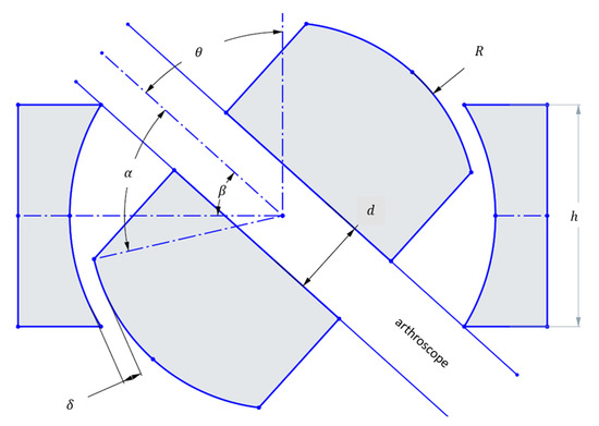
Figure 1.
Geometric parameters of a ball joint used for calculation of the maximum rotation angle which can achieve the 120 included angle conical workspace set as a design requirement (126° included angle is a 1.05 design factor).
At the maximum θ, the arthroscope collides with the edge of the housing. Then,
Using the design parameters from Table 1, and the above formulas, one can use a numerical solver to obtain the value of h. Here, the numerical solver SymPy 1.12 is used.

Table 1.
Defined parameters to be used for workspace fulfillment.
This ensures that the maximum angle to the vertical created by the scope is sufficient to replicate the workspace present in conventional knee arthroscopy, plus a design factor of 1.05 to account for the center of motion not being at the incision, but rather at the ball joint. The surgeon limits this difference in center of motion by placing the ball joint as close to the incision as possible. However, this misalignment may introduce additional stress on the tissue surrounding the incision. As a proof-of-concept, these effects were beyond the scope of the present study. Future development will explore solutions such as incorporating a gimbal-type apparatus, with the aim of eliminating misalignment and reducing tissue loading in a clinical setting.
On the other hand, dimensions not needed for workspace fulfillment are the through-hole diameter and the height of the ball. Firstly, to facilitate the insertion and removal of the arthroscope through the ball joint, the diameter of the through-hole is selected to be 4.4 mm, which is 0.4 mm greater than the diameter of the scope. Secondly, the height of the ball is chosen to be 16 mm, so that the inner clamp surface may make contact with the ball for most angles to the vertical, and enough space is left for the deformed structures to occupy, and enough thickness is given to the structures so that they may not fracture. The dimensions of the slits may be seen in Figure 2.
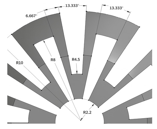
Figure 2.
Dimensions of the slits made in the ball joint.
The overall device makeup is shown in Figure 3. Some components are readily available to be purchased, such as cam locks and the flexible arm. Others are custom-made and 3D printed, such as the end-effector assembly minus the motor. Adapters, seen in green and gray, are rigidly attached onto the shin pad, through which straps thread for securing the pad onto the shank. Cam locks are used to restrict the motion of the crank, which can rotate freely when cam locks are not clamping. Screw threads are present on both ends of the flexible arm, so brass inserts are used to connect the flexible arm with the crank and the end-effector body.
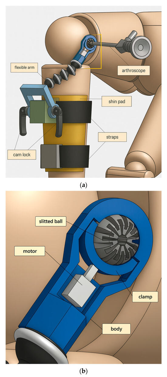
Figure 3.
(a) Overall components of device to be fitted on patient’s injured, operative leg. (b) Components of miniature braking system for tool suspension (the end-effector).
In the end-effector assembly, grooves are designed into the body so that the clamp does not fall out of place and can only travel in the clamping direction. The motor is any device which can provide a clamping force towards the slit ball. As seen in the prototyping below, the motor is chosen to be a miniature air cylinder.
2.3. Finite Element Analysis
The point of interest for finite element analysis is the stress and deformation of the ball joint when under the clamping force without the arthroscope inserted, and the force which resists the arthroscope sliding along the ball through-hole when clamping is activated with the scope inserted. Abaqus was the program chosen to run the simulations for this analysis. After the design was made in Onshape 1.180, an ACIS file was downloaded and imported into Abaqus. Then, the part was assigned a material, which was polyethylene, and its corresponding mechanical properties are shown in Table 2. To mesh the components, the clamp was given a hex mesh of size 1 mm, the ball a hex mesh of size 0.8 mm, while the body was given a hex mesh of size 1 mm.
Table 2.
Mechanical properties of selected material, polyethylene.
2.3.1. Without Arthroscope Inserted
The simulation is first run without the arthroscope through the ball, and the maximum deformation of the slit ball is recorded at various angles to the vertical. After meshing, loads and boundary conditions are defined to be as realistic as possible. To demonstrate the compressibility of the ball joint and model the clamping of an actuator, a concentrated force of 10 N is applied at the center of the clamp in the clamping direction, which is the negative y-direction in Figure 4. The boundary conditions for this analysis are listed in Table 3 and also graphically shown in Figure 4.
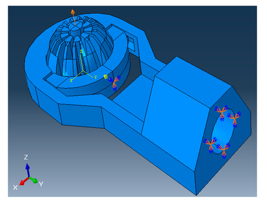
Figure 4.
A 10N load is applied to clamp and compress the ball joint, and all boundary conditions defined on the model during the simulation with scope are inserted.
Table 3.
Boundary conditions for ball deformation testing without arthroscope.
Abaqus is set to detect general contact between parts, with contact properties between certain surfaces specified by their matching coefficient of friction listed in Table 2. For every simulation, the “Dynamic, Explicit” package is used, the precision is set to “Double—analysis + packager”, and the Nodal output precision is set to “full”. Starting with the ball making a 0° angle with the vertical, the simulation is repeated for every 10° turned in the xz-plane, with the axis of rotation as the negative x-axis following right-hand convention (refer to Figure 4).
2.3.2. With Arthroscope Inserted
Next, the more realistic situation is tested, where ball deformation is observed with the arthroscope inserted into the through-hole. In Abaqus, a 20 mm long cylinder with a diameter of 4 mm is made to represent a section of an arthroscope. Then, this section is given a hex mesh of size 0.8 mm and is placed through the ball joint. The outer surface of the section is assigned to be stainless steel, with general contact between the clamp and the section defined with a friction coefficient of 0.2 (see Table 2).
For this simulation, the analysis is divided into two steps. In step 1, the ball is compressed under the applied load, until it fully clamps the arthroscope inside and reaches dynamic equilibrium, with a step time of 0.5. In step 2, full clamping is left activated from step 1, the top node of the section is assigned a linear displacement of constant velocity in the positive z-direction (refer to Figure 4), with a step time of 1.0. The said displacement has a “Tabular” amplitude, which is 0 at step time 0, and 4 at step time 1. Because of the sufficient length of the cylindrical section, the displacement has a “Tabular” amplitude, which is 0 at step time 0, and 4 at step time 1 during step 2.
Here, the goal is to record how much reaction force in the direction along the through-hole prevents the scope from sliding during clamping. The boundary conditions are like those used in the previous testing without the arthroscope, with the addition of a displacement of the cylindrical section, all of which are listed in Table 4. Figure 4 shows the load applied and the boundary conditions used in this instance.
Table 4.
Boundary conditions for analysis with arthroscope.
Just as in the previous analysis without the arthroscope inserted, the “Dynamic, Explicit” package is used, the precision is set to “Double − analysis + packager”, and the Nodal output precision is set to “full”. These settings are highly recommended to achieve the high accuracy of the simulation output. In all test cases, the ball is vertically oriented. Results are recorded for all combinations of clamping forces of 5, 10, 15, and 20 newtons, and friction coefficients of 0.2 and 0.3.
After the design and FEA processes suggest a potentially feasible piece of hardware, prototyping is the next step in fabricating the device. First, custom-made parts are exported as an STL file from Onshape. Using PrusaSlicer 2.7.1, the models are sliced and the G-code for printing them is generated. They are then 3D printed using an Ender-3 (Creality®, Shenzhen, China) with PLA as the filament. To avoid printing unnecessary support structures for overhangs, protruding features are designed to rise at a 45° angle to the horizontal.
3. Results
3.1. FEA Without Arthroscope Inserted
Here, the Abaqus FEA simulation results for each ball orientation are presented. One instance of the von Mises stress and deformation in the ball joint assembly is shown in Figure 5a and Figure 5b, respectively. Moreover, the maximum deformation recorded at each ball angle under clamping is reported in Figure 6.
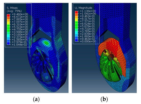
Figure 5.
The ball inside the housing is turned 60° to the vertical and applied with a clamping force. The simulation results show (a) The von Mises stress observed in MPa. (b) The deformation observed in mm.
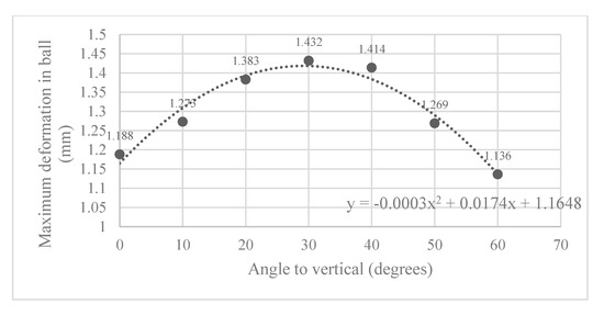
Figure 6.
Maximum deformation observed in slit ball joint at various angles to the vertical.
3.2. FEA with Arthroscope Inserted
Next, the structural analysis with the arthroscope inserted is examined, where step 1 in the case of the 10 N clamping force is graphically illustrated in Figure 7. Furthermore, Figure 8 shows the contact forces in the positive z-direction between the arthroscope and the inner surfaces of the slit ball as the arthroscope is pulled upwards with a friction coefficient of 0.2. The von Mises stresses occurring in the ball joint assembly during full clamping after step 1 is reported in Figure 9, where the maximum stresses are listed for each clamping force. One may also be interested in the mean of the contact forces over time for each clamping force, and this is demonstrated in Figure 10 (since the meaningful values of the contact force are those occurring during step 2, only those values are included in the calculations). Figure 11 compares the contact forces in the same manner as Figure 8, but with the friction coefficient of 0.3. And, finally, one can see the increase in the contact forces due to an increase in the friction coefficient in Figure 12, as the contact forces under 5 N of clamping force is shown for friction coefficients of both 0.2 and 0.3.
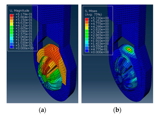
Figure 7.
The ball inside the housing has a cylindrical section inserted and is applied with a clamping force. (a) The von Mises stress observed in MPa. (b) The deformation observed in mm.
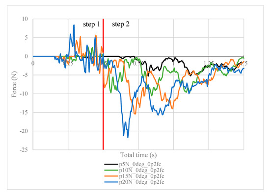
Figure 8.
Contact force (N) measured in the positive z-direction between the arthroscope and the inner surfaces of the deformed ball, where friction coefficient is 0.2.
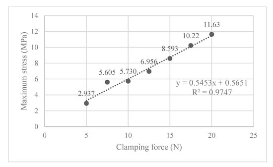
Figure 9.
The maximum von Mises stress occurring in the ball joint assembly for each clamping force, where the ball is vertically oriented.
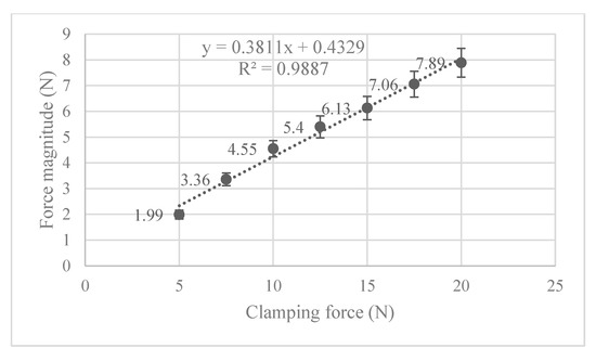
Figure 10.
Mean contact force for each clamping force and their respective 95% confidence interval for true mean.
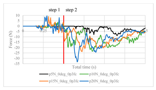
Figure 11.
Contact force (N) measured in the positive z-direction between the arthroscope and the inner surfaces of the deformed ball, where friction coefficient is 0.3.
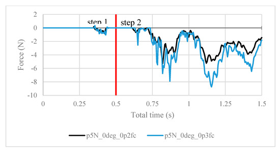
Figure 12.
Contact forces under 5 N of clamping force, with friction coefficients of both 0.2 and 0.3.
3.3. Prototyping
Though the device comprises many components, the most vital piece is the slit ball joint assembly. Figure 13 shows the ball joint assembly specifically, though without an actuator to provide the clamping force. Nonetheless, when clamping force is present, the profile of the center perimeter becomes an ellipse whose minor axis is aligned with the clamping direction, consistent with the deformed result computed by FEA (see Figure 7).
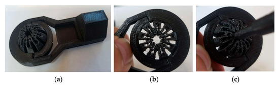
Figure 13.
(a) The 3D-printed rod end using PLA; (b) deformation of the slit ball with the clamping force applied without the scope; and (c) deformation of the slit ball with the clamping force applied with the scope.
4. Conclusions and Discussion
The ball joint assembly is tested as part of a semi-robotic device for knee arthroscopy, where a tool inserted into the through-hole of the ball joint is clamped and suspended. The whole assembly was successfully printed using additive manufacturing as a prototype. Abaqus FEA simulation shows that the maximum von Mises stress and the magnitude of contact forces positively correlate with the clamping force, where the stress incurred is still in the elastic range of polyethylene (the material selected). Future research will focus on implementing the actuator into the ball joint assembly and developing a safety mechanism for the device, as well as gathering feedback from surgeons to better adapt it to surgical use.
The ball joint assembly exhibited desirable compressibility for use in arthroscope clamping. Polyethylene is chosen to be the material whose properties are used in the FEA simulation because of its availability for rapid prototyping as well as its elastic properties. Its yield stress of 19 MPa [30] is greater than the stresses incurred during clamping in the ball joint assembly (see Figure 9), displaying its suitability for proof-of-concept testing. In terms of fatigue analysis, since the maximum stress is only 61% of the yield stress (11.63/19), the loading level is unlikely to trigger the high-cycle or low-cycle fatigue of the material. However, polyethylene is not ideal for surgical use due to its low sterilization capability and reduced long-term durability. For the transition into clinical practice, alternative medical-grade materials such as polyether ether ketone (PEEK) and stainless steel will be explored. Further research is needed to determine a suitable material for the clinical use of this device.
It is worth noting the following trends in the contact forces graphs shown above. In step 1, fluctuations in the contact force are due to the inner surfaces of the ball touching the arthroscope and pushing it against the other side of the ball. These values are insignificant in finding the force resisting the scope from sliding. In step 2, the results are as expected. In Figure 8, the maximum contact force magnitude increases as the clamping force increases. As the arthroscope section keeps being displaced, the contact force gradually decreases. The same trend is shown in Figure 11, though the results are greater in magnitude due to the greater friction coefficient, which is expected. One case of this is also confirmed in Figure 12, where the contact forces under 5 N clamping for both the 0.2 and 0.3 friction coefficient are compared.
Also of interest, is seeing how the von Mises stress and mean contact force change with increasing clamping force. Figure 9 shows that the maximum von Mises stress observed is positively correlated to the clamping force, and none of them exceed the 19 MPa yield stress limit. In Figure 10, the magnitude of the mean contact force positively correlates with the clamping force, and so does the standard deviation of contact forces under each clamping force.
Further testing of the device is needed. In computer analyses, more realistic loading conditions may be tested by seeing how the assembly withstands external torque on the arthroscope, or how different weights of the arthroscope may strain the assembly. The contact friction force computation above may also be tested in real life by using a load cell to pull the arthroscope along the through-hole under clamping, after the clamping mechanism has been designed. In this way, one seeks to compare computer-generated results to experimental testing, which helps to certify whether the feasibility shown here is realistically true.
Author Contributions
Conceptualization, T.H. and S.-E.S.; Data curation, T.H. and Y.B.; Formal Analysis, T.H. and Y.B.; Investigation, T.H., Y.B. and S.-E.S.; Methodology, T.H., Y.B. and S.-E.S.; Project administration, Y.B. and S.-E.S.; Supervision, Y.B. and S.-E.S.; Visualization, T.H.; Writing—original draft, T.H., Y.B. and S.-E.S.; Writing—review and editing, T.H., Y.B., A.Q., S.A. and S.-E.S.; All authors have read and agreed to the published version of the manuscript.
Funding
This research received no external funding.
Data Availability Statement
The raw data supporting the conclusions of this article will be made available by the authors on request.
Conflicts of Interest
The authors declare no conflicts of interest.
Abbreviations
The following abbreviations are used in this manuscript:
| KA | Knee Arthroscopy |
| MIS | Minimally Invasive Surgery |
| SLAM | Simultaneous Localization and Mapping |
| FEA | Finite Element Analysis |
| MPa | Megapascal |
| PLA | Polylactic Acid |
| STL | Stereolithography file format |
| G-code | Geometric Code |
| OR | Operating Room |
| ACIS | Andy, Charles, Ian’s System |
References
- Jackson, R.W. From the Scalpel to the Scope: The History of Arthroscopy. Bayl. Univ. Med. Cent. Proc. 1996, 9, 77–79. [Google Scholar] [CrossRef]
- McKeon, B.P.; Bono, J.V.; Richmond, J.C. Knee Arthroscopy; Springer: New York, NY, USA, 2009; pp. 1–202. [Google Scholar] [CrossRef]
- Phillips, B.B. General Principles of Arthroscopy. In Campbell’s Operative Orthopaedics; Elsevier: Amsterdam, The Netherlands, 2013; pp. 2364–2377.e1. Available online: https://cigarboxarthroscopy.com/wp-content/uploads/2016/03/general-arthroscopy.pdf (accessed on 12 September 2025).
- Vitiello, V.; Lee, S.L.; Cundy, T.P.; Yang, G.Z. Emerging Robotic Platforms for Minimally Invasive Surgery. IEEE Rev. Biomed Eng. 2013, 6, 111–126. [Google Scholar] [CrossRef]
- Baker, B.E.; Peckham, A.C.; Pupparo, F.; Sanborn, J.C. Review of Meniscal Injury and Associated Sports. Am. J. Sports Med. 1985, 13, 1–4. [Google Scholar] [CrossRef]
- Mack, M.J. Minimally Invasive and Robotic Surgery. JAMA 2001, 285, 568–572. [Google Scholar] [CrossRef]
- Fox, A.J.S.; Bedi, A.; Rodeo, S.A. The Basic Science of Human Knee Menisci: Structure, Composition, and Function. Sports Health 2012, 4, 340–351. [Google Scholar] [CrossRef]
- Kim, J.; Kim, Y.; Cho, K.J.; Kim, K. Development and Preclinical Trials of a Novel Steerable Cannula for 360° Arthroscopic Capsular Release in Minimally Invasive Surgery. In Proceedings of the 42nd Annual International Conference of the IEEE Engineering in Medicine & Biology Society (EMBC), Montreal, QC, Canada, 20–24 July 2020; pp. 4890–4894. [Google Scholar] [CrossRef]
- Cui, Z.; Han, Z.; Pan, H.; Shao, Y.; Zhu, D. Design of a 3-Axial Force/Torque Sensor for Arthroscopy Force Sensing. In Proceedings of the IEEE International Conference on Mechatronics and Automation, ICMA, Beijing, China, 7–10 August 2011; pp. 243–248. [Google Scholar] [CrossRef]
- Nai, T.Y.; Herder, J.L.; Tuijthof, G.J.M. Steerable Mechanical Joint for High Load Transmission in Minimally Invasive Instruments. J. Med. Devices Trans. ASME 2011, 5, 034503. [Google Scholar] [CrossRef]
- Long, Z.; Nagamune, K.; Kuroda, R.; Kurosaka, M. Real-Time 3D Visualization and Navigation Using Fiber-Based Endoscopic System for Arthroscopic Surgery. J. Adv. Comput. Intell. Intell. Inform. 2016, 20, 735–742. [Google Scholar] [CrossRef]
- Fasel, L.; Gerig, N.; Cattin, P.C.; Rauter, G. The SEA-Scope: Torque-Limited Endoscopic Joint Control for Telemanipulation or Visual Servoing through Tendon Force Control with Series Elastic Actuation. In Proceedings of the International Symposium on Medical Robotics, ISMR, Atlanta, GA, USA, 17–19 November 2021. [Google Scholar] [CrossRef]
- Kosa, G.; Aiello, G.; Zam, A.; Cattin, P.C.; Rauter, G. Automation of a Flexoscope for Laser Osteotomy. In Proceedings of the CAOS 2017 17th Annual Meeting of the International Society for Computer Assisted Orthopaedic Surgery, Aachen, Germany, 14–17 June 2018; Volume 1, pp. 166–171. [Google Scholar] [CrossRef]
- Eugster, M.; Duverney, C.; Karnam, M.; Gerig, N.; Cattin, P.C.; Rauter, G. Robotic Endoscope System for Future Application in Minimally Invasive Laser Osteotomy: First Concept Evaluation. IEEE Trans. Med. Robot. Bionics 2022, 4, 621–633. [Google Scholar] [CrossRef]
- Marmol, A.; Corke, P.; Peynot, T. ArthroSLAM: Multi-Sensor Robust Visual Localization for Minimally Invasive Orthopedic Surgery. In Proceedings of the IEEE/RSJ International Conference on Intelligent Robots and Systems (IROS), Madrid, Spain, 1–5 October 2018; pp. 3882–3889. [Google Scholar] [CrossRef]
- Razjigaev, A.; Pandey, A.K.; Howard, D.; Roberts, J.; Wu, L. End-to-End Design of Bespoke, Dexterous Snake-Like Surgical Robots: A Case Study with the RAVEN II. IEEE Trans. Robot. 2022, 38, 2827–2840. [Google Scholar] [CrossRef]
- Ciszkiewicz, A.; Milewski, G. Path Planning for Minimally-Invasive Knee Surgery Using a Hybrid Optimization Procedure. Comput. Methods Biomech. Biomed. Engin. 2018, 21, 47–54. [Google Scholar] [CrossRef] [PubMed]
- Al Mulhim, F.A.; AlSaif, H.E.; Alatiyah, M.H.; Alrashed, M.H.; Balghunaim, A.A.; Almajed, A.S. The Prevalence of Musculoskeletal Pain (MSP) Among Orthopedic Surgeons and Residents in Saudi Arabia’s Eastern Area. Cureus 2023, 15, e39246. [Google Scholar] [CrossRef]
- Bartholomew, A.J.; Houk, A.K.; Pulcrano, M.; Shara, N.M.; Kwagyan, J.; Jackson, P.G.; Sosin, M. Meta-Analysis of Surgeon Burnout Syndrome and Specialty Differences. J. Surg. Educ. 2018, 75, 1256–1263. [Google Scholar] [CrossRef]
- Weigl, M.; Antoniadis, S.; Chiapponi, C.; Bruns, C.; Sevdalis, N. The Impact of Intra-Operative Interruptions on Surgeons’ Perceived Workload: An Observational Study in Elective General and Orthopedic Surgery. Surg. Endosc. 2015, 29, 145–153. [Google Scholar] [CrossRef] [PubMed]
- Jaiprakash, A.; O’Callaghan, W.B.; Whitehouse, S.L.; Pandey, A.; Wu, L.; Roberts, J.; Crawford, R.W. Orthopaedic Surgeon Attitudes towards Current Limitations and the Potential for Robotic and Technological Innovation in Arthroscopic Surgery. J. Orthop. Surg. 2017, 25, 2309499016684993. [Google Scholar] [CrossRef]
- Randell, R.; Honey, S.; Alvarado, N.; Greenhalgh, J.; Hindmarsh, J.; Pearman, A.; Jayne, D.; Gardner, P.; Gill, A.; Kotze, A.; et al. Factors Supporting and Constraining the Implementation of Robot-Assisted Surgery: A Realist Interview Study. BMJ Open 2019, 9, e028635. [Google Scholar] [CrossRef]
- Price, A.J.; Erturan, G.; Akhtar, K.; Judge, A.; Alvand, A.; Rees, J.L. Evidence-Based Surgical Training in Orthopaedics: How Many Arthroscopies of the Knee Are Needed to Achieve Consultant Level Performance? Bone Jt. J. 2015, 97–B, 1309–1315. [Google Scholar] [CrossRef]
- Strydom, M.; Crawford, R.; Roberts, J.; Jaiprakash, A. Robotic Arthroscopy: The Uncertainty in Internal Knee Joint Measurement. IEEE Access 2019, 7, 168382–168394. [Google Scholar] [CrossRef]
- Opie, J.; Jaiprakash, A.; Ploderer, B.; Crawford, R.; Brereton, M.; Roberts, J. Understanding the Challenges and Needs of Knee Arthroscopy Surgeons to Inform the Design of Surgical Robots. In Proceedings of the OzCHI’18: 30th Australian Computer-Human Interaction Conference, Melbourne, Australia, 4–7 December 2018; pp. 458–462. [Google Scholar] [CrossRef]
- Freisberg, D.; Eschweiler, J.; Lauer, W.; Radermacher, K. Development of an Assistance System for Arthroscopic Surgery. IFMBE Proc. 2009, 25, 186–188. [Google Scholar] [CrossRef] [PubMed]
- Cooper, D.E. Single Portal Knee Arthroscopy: 2015 Technique Update. Arthrosc. Tech 2016, 5, e17–e22. [Google Scholar] [CrossRef] [PubMed]
- Ward, B.D.; Lubowitz, J.H. Basic Knee Arthroscopy Part 1: Patient Positioning. Arthrosc. Tech 2013, 2, e497–e499. [Google Scholar] [CrossRef]
- Mor, A. 5 DOF Force Feedback Using the 3 DOF Phantom and a 2 DOF Device. Proceedings of the third PHANToM Users Group Workshop, AI Lab Technical Report. 1998. Available online: https://dspace.mit.edu/handle/1721.1/4135 (accessed on 12 September 2025).
- Xu, M.M.; Huang, G.Y.; Feng, S.S.; McShane, G.J.; Stronge, W.J. Static and Dynamic Properties of Semi-Crystalline Polyethylene. Polymers 2016, 8, 77. [Google Scholar] [CrossRef] [PubMed]


Disclaimer/Publisher’s Note: The statements, opinions and data contained in all publications are solely those of the individual author(s) and contributor(s) and not of MDPI and/or the editor(s). MDPI and/or the editor(s) disclaim responsibility for any injury to people or property resulting from any ideas, methods, instructions or products referred to in the content. |
© 2025 by the authors. Licensee MDPI, Basel, Switzerland. This article is an open access article distributed under the terms and conditions of the Creative Commons Attribution (CC BY) license (https://creativecommons.org/licenses/by/4.0/).