1. Introduction
In large-scale mining of coal resources in China, solid waste rock is produced and the discharge thereof accounts for about 10–15% of coal production [
1,
2,
3,
4]. There are many sources of waste rock: roof and floor material, as well as partings in the mining of coal seams and that produced in roadway tunnelling. In general, the processing thereof involves transporting waste rock and stockpiling it [
5,
6,
7]. Waste rock dumps occupy large areas of land and pollute the air by spontaneous combustion, and contaminate soil and underground water as a result of rainfall [
8,
9,
10,
11]. In addition, waste rock dumps also lead to serious geological disasters, such as collapses and landslides [
12,
13,
14,
15]. To solve a series of difficulties resulting from the discharge of waste rocks, scholars proposed backfilling goafs with waste rocks [
16,
17]. Waste rocks are filled into underground goafs, which not only processes otherwise waste but also controls stratum movement and surface subsidence [
18]. Such a method for backfilling has significant social, economic, and environmental benefits, so it is of wide interest. After filling crushed waste rocks into goafs, crushed waste rocks are gradually deformed due to compaction under the pressure from overlaying strata. Therefore, compaction characteristics of waste rock play a decisive role in the backfilling effect [
19,
20]. If a certain lateral stress is applied beforehand, the waste rocks for backfilling are densified, thus improving resistance to deformation. Therefore, it is particularly important to study the influence of lateral loading stress on compaction characteristics of waste rocks used for backfilling.
Scholars have investigated the compaction characteristics of crushed waste rocks and obtained a series of beneficial research results. For example, by studying compaction characteristics of collapsed rock blocks in goafs, Pappas and Mark [
21] obtained relationships linking tangent and secant moduli to the stress applied during compaction of rock blocks. Moreover, by using Salamon and Terzaghi formulae, they described the stress–strain relationship. By utilising a steel cylinder, Zhang et al. [
22] tested the crushing strength of samples with particle sizes of 15–20 mm, 20–25 mm, and 25–30 mm under different pressures. Through compaction tests on an RMT-150B electro-hydraulic servo test system, and by utilising a steel drum for compaction, Su et al. [
23] obtained the stress–strain relationship of crushed rocks in compaction test conditions and analysed the influence of rock strength, block size, and compaction stress on the compaction characteristics of crushed rocks. Zhang [
24] and Zhang et al. [
25,
26] put forward a fractal model for compaction and crushing of waste rocks so as to study the fractal characteristics of crushed waste rocks under compaction. Moreover, they conducted compaction tests under different compaction stresses and particle size distributions, thus verifying that the theoretical model is reasonable. By combining the YAS5000 testing machine (Kexin, Changchun, China) with a self-designed compaction device, Li et al. [
27] investigated the effects of particle size on compaction characteristics of waste rocks used for backfilling. Based on this, they found that large particles of waste rocks can form a skeletal structure when used as backfill while the small particles can fill the gaps between larger particles. Therefore, a reasonable size distribution of large and small particles is more beneficial to improving compressive performances of waste rock used for backfilling. In addition, Ma Dan et al. [
28] tested compaction characteristics of limestone particles by utilising an MTS815.02 test system and self-developed test device to assess the effects of particle size distribution on porosity changes during compaction. In conclusion, although the compaction characteristics of crushed waste rocks are known, the influences of lateral loading stress on compaction characteristics thereof have not been elucidated.
In view of this, after introducing the preparation method for samples of crushed waste rocks, we tested the compaction characteristics of crushed waste rocks by utilising a self-developed bidirectional loading test system for granular materials. Then, the influence of lateral loading stress on the compaction characteristics was explored. Moreover, we analysed the effects of change in lateral strain, axial strain, porosity, lateral stress, and lateral pressure coefficient of the samples of crushed waste rocks used for backfilling in lateral and axial loading and established the relationship between lateral loading stress and compaction characteristics thereof. This provides a theoretical base for improving backfilling effects in goafs.
2. Sample Preparation and Test Equipment
2.1. Sample Preparation and Test Scheme
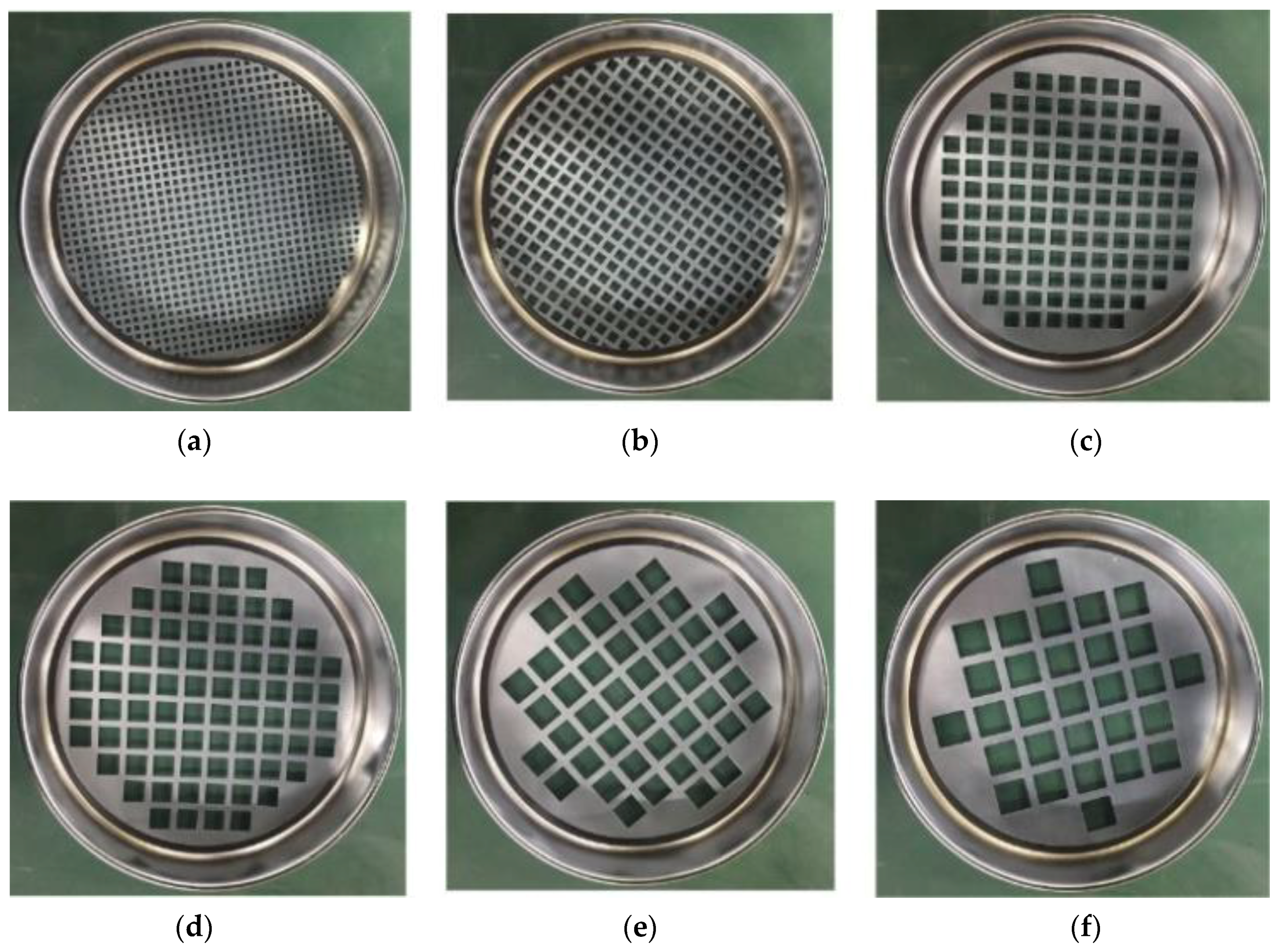
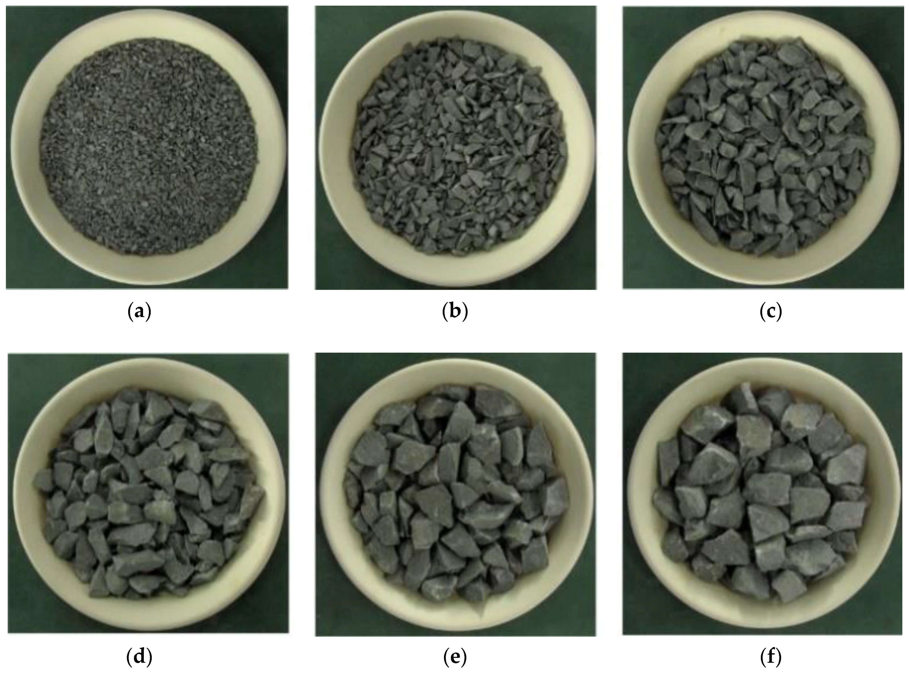
Samples of crushed waste rocks were mainly used in this study. The waste sandstone was collected from coal mines and prepared to form samples of waste rock. Before testing, we crushed the waste rock to a 50 mm downgrade and then further crushed to 30 mm down. Samples were then graded through 5, 10, 15, 20, 25 and 30 mm (
Figure 1) and the screened samples of crushed sandstones with different particle sizes are seen in
Figure 2.
The compaction characteristics of waste rocks for backfilling are mainly affected by four factors: lithology, particle size distribution, lateral stress, and number of lateral loading cycles. This test focused on the influence of lateral stress on compaction characteristics of waste rock used for backfilling. Based on the situations encountered during backfill coal mining on site, lateral stresses were set to be 0, 1, 2 and 3 MPa and the samples used were sandstones with particle sizes ranging from 0 to 30 mm. Five cycles of lateral loading were applied.
By keeping lithology, particle size distribution and lateral loading times of the samples constant and only changing the lateral stress applied to the samples, the effects of lateral stress on compaction characteristics of waste rocks used for backfilling were analysed.
2.2. Design of Test Equipment
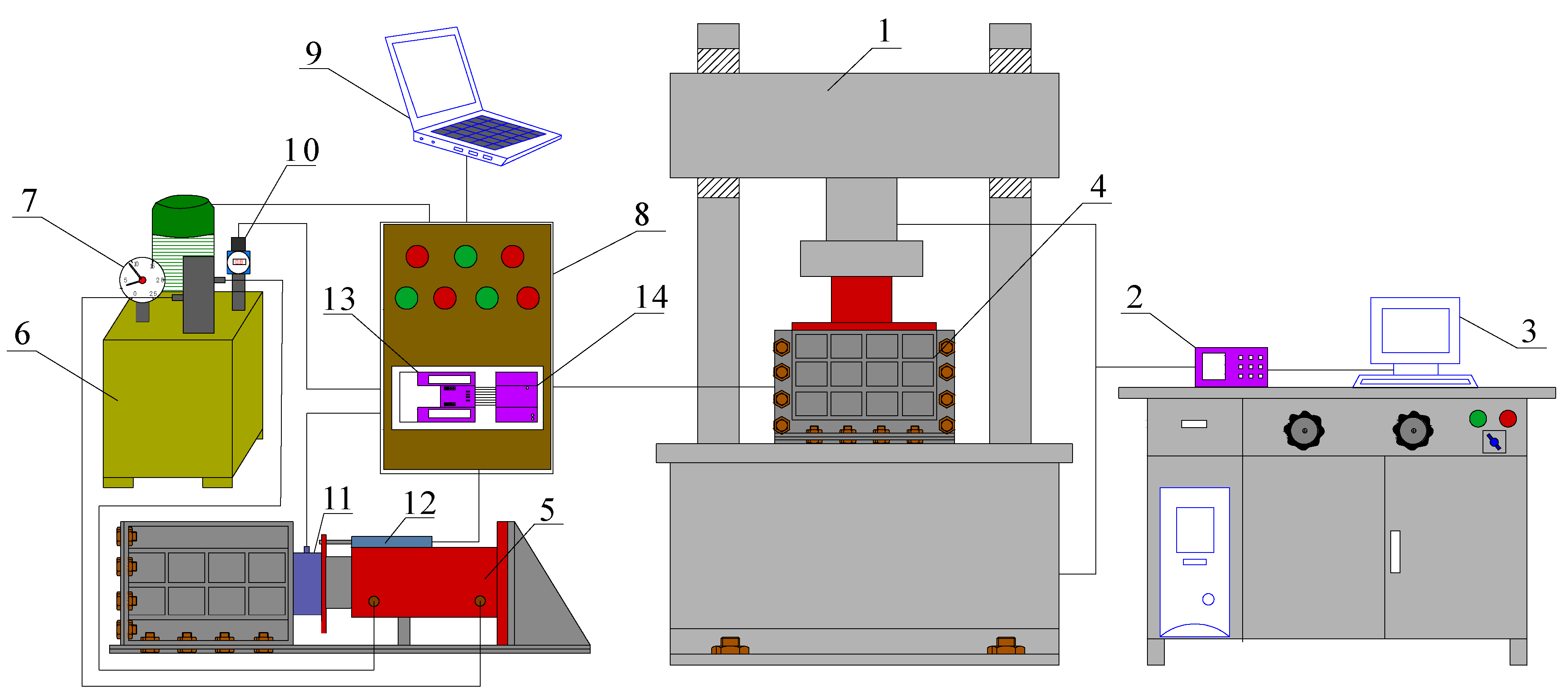
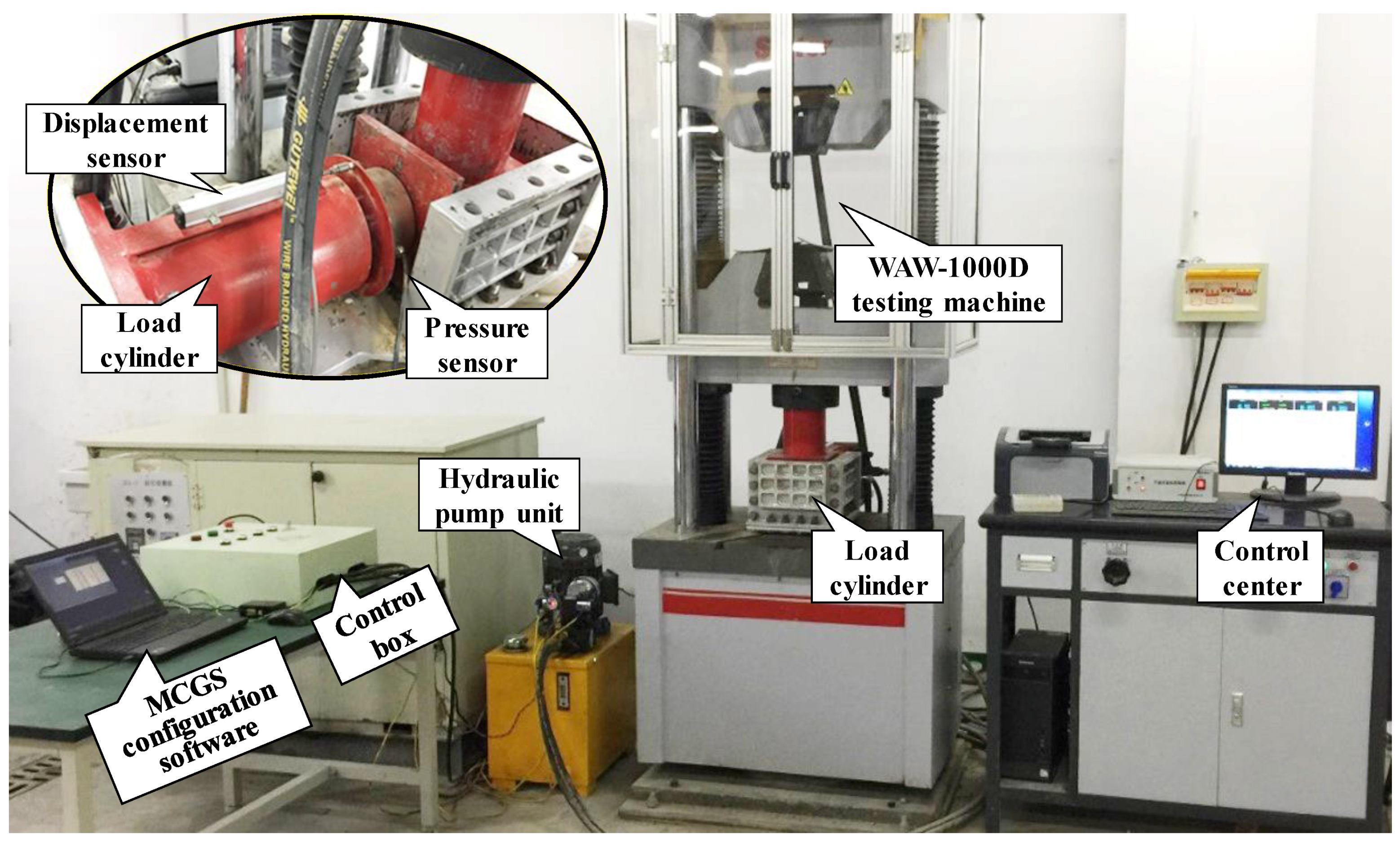
By employing a self-designed bidirectional loading test system for granular materials, the compaction characteristics of waste rocks used for backfilling were tested. This system comprises an axial loading system and a lateral loading system, which can realise lateral and axial loading of the crushed waste rock samples, as shown in
Figure 3. The axial loading system consists mainly of the WAW-1000D electro-hydraulic servo testing machine (Sinter, Changchun, China). The lateral loading system includes a hydraulic pump unit, an oil cylinder for loading, a control box, a pressure sensor, a displacement sensor, a laptop, and a data acquisition device (
Figure 4).
The WAW-1000D electro-hydraulic servo testing machine (1) can offer continuous and stable axial pressures at a maximum axial load of 1000 kN. The testing machine with a travel of 250 mm is connected to the controller (2) and computer (3) to monitor and acquire pressure and displacement data (under axial load) in real time. The loading box (4) provides effective loading space measuring 250 mm × 200 mm × 200 mm (length × width × height) for the samples. The hydraulic pump unit (6) offers lateral loading pressures required in testing in the oil cylinder (5), thus realising lateral loading and unloading of the samples. The whole process is controlled by the control box (8). The pressure gauge (7) and the pressure transmitter (10) can display the oil pressure in the pump unit in real time. Furthermore, pressure and displacement data during lateral loading are monitored in real time by using the pressure sensor (11) and the displacement sensor (12) and are transformed into current signals. Through the FX2N-5a analogue input and output modules (14), the signals are collected and transmitted to the PLC controller (13), thus completing data acquisition in the lateral loading process. Finally, by connecting the PLC controller to the laptop (9), a data transmission channel is established to store data and import data into text files for post-processing.
3. Test Procedure
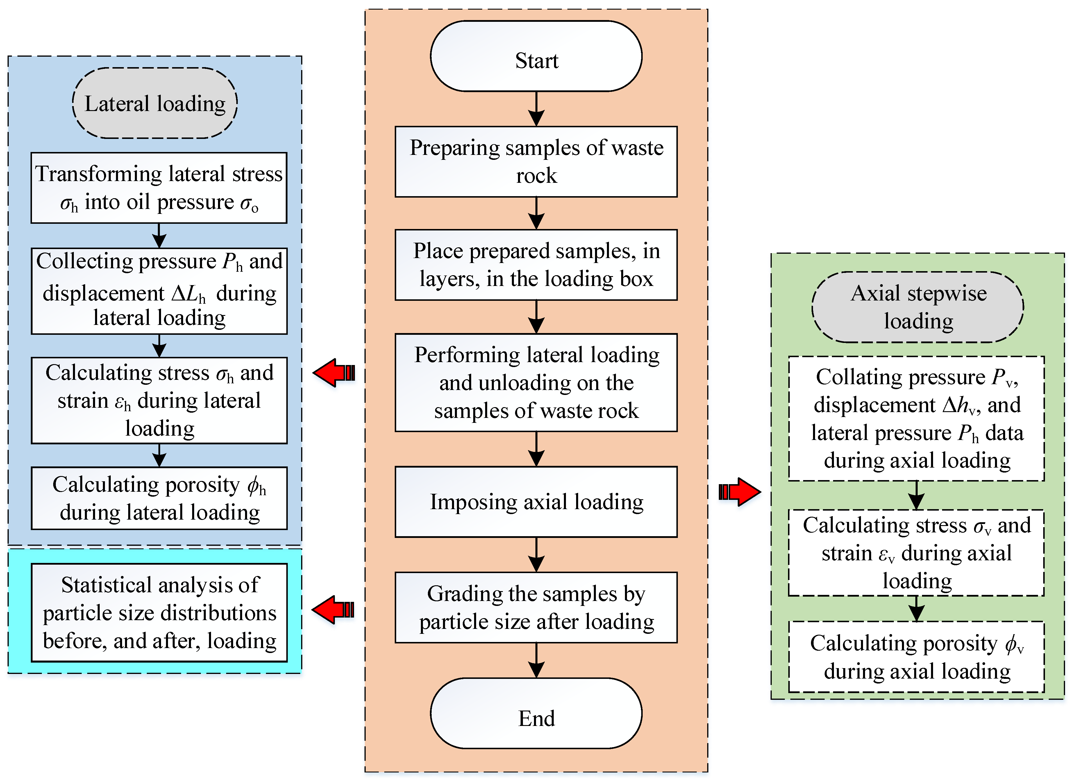
To study the influence of lateral stress on compaction characteristics of these crushed waste rock samples, compaction tests were conducted on waste rocks used for backfilling under four lateral stresses (0, 1, 2 and 3 MPa) in combination with the bidirectional loading test system for granular materials. Moreover, the influence of lateral stress on the compaction characteristics of waste rocks used for backfilling was analysed. The specific test steps are shown in
Figure 5.
The test included five main steps: preparing the samples of crushed waste rocks, layering the prepared samples of crushed waste rocks into the loading box, lateral loading, axial loading and screening the samples after loading. The compaction test method of solid backfill materials promulgated by China’s National Energy Administration [
29] was adopted to test the compaction characteristics of crushed waste rocks used for backfilling.
(1). Preparing the samples of crushed waste rocks.
The preparation scheme for the samples is described in
Section 2.1.
(2). Layering the prepared samples of crushed waste rocks into the loading box.
Before loading the samples, the loading box needed to be assembled and the displacement and pressure sensors reset to zero. Then, the prepared samples were divided into 3–6 layers and placed in the loading box. After loading each layer, the surface of each layer was not very smooth; thus, the samples needed to be pre-compacted. Pre-compaction can make the surface of each layer smooth, and the experimental error can be greatly reduced. The total height of the loaded samples in each group of tests was 200 mm and the mass of each group of samples was recorded. After the whole loading box was fully loaded, the upper cover plate was bolted on and the loading box placed on the test bench of the WAW-1000D electro-hydraulic servo testing machine.
(3). Lateral loading.
The power to the equipment was switched on and the MCGS software was run to monitor pressure and displacement data. According to the lateral stress set in this test scheme, the corresponding oil pressure was calculated. The oil pressure was adjusted on the pressure gauge and the lateral loading was applied to the samples through the control box. Furthermore, the lateral pressure and displacement during lateral loading were monitored and recorded in real time.
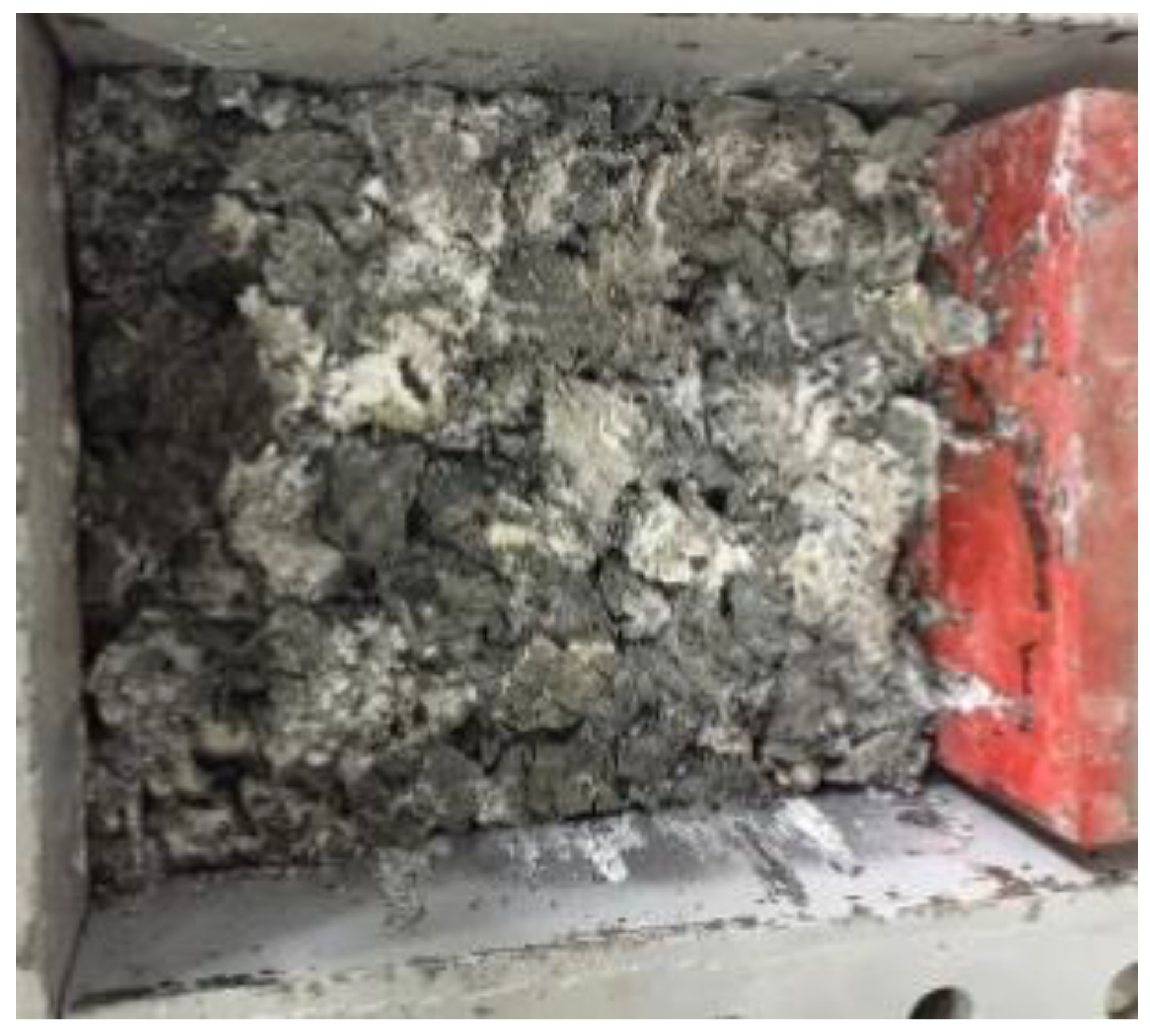
(4). Axial loading.
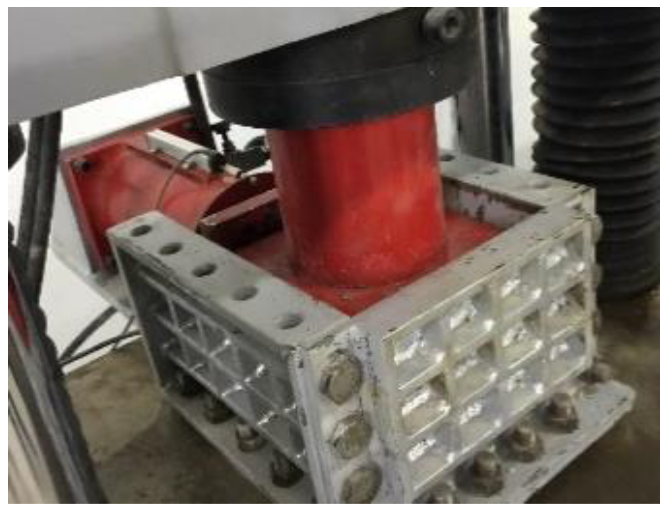
After lateral loading, the upper cover plate was removed. At this time, due to the small elastic rebound of the waste rocks, the height of the samples was slightly higher than 200 mm (the height of the loaded samples). The upper press plate was placed on the samples and pre-compaction conducted by using the testing machine to restore the height of the samples to 200 mm. Then, the pressure applied during axial loading was set and an axial load applied to the samples (
Figure 6). Lateral pressure, axial pressure, and axial displacement data under axial loading were monitored and recorded in real time.
(5). Screening the samples after loading.
After completing the axial loading of the samples, the samples were graded. The particle crushing and the particle size distribution of the samples before and after loading were obtained (
Figure 7).
4. Calculation of Compaction Parameters
4.1. Lateral Strain and Porosity
(1). Transformation from lateral stress to oil pressure in lateral loading.
For the oil cylinder for loading, lateral loading was performed on the samples through oil pressure. Lateral stress here refers to the compressive stress applied to the samples. Therefore, it was necessary to transform the lateral stress into an oil pressure and apply lateral loading to the samples under different lateral stresses. The relationship between oil pressure
σo and lateral stress
σh is expressed as:
where
Ah,
Lh and
hh indicate the area, length and height of the side-push plate, respectively;
Ao and
ro represent the cross-sectional area and the radius of the oil cylinder, respectively.
By substituting these known parameters, such as the length of the side-push plate, the height of the side-push plate and the radius of the oil cylinder into Formula (1), the oil pressure was calculated to be 3.3, 6.5 and 9.8 MPa when the lateral stress was 1, 2 and 3 MPa, respectively.
(2). Calculating lateral strain of the samples under lateral load.
Lateral stress
σh on the samples under lateral loading is the ratio of the lateral loading pressure to the area of the side-push plate:
where
Ph represents the lateral loading pressure of the samples. The lateral strain
εh in the samples under lateral loading is the ratio of the lateral loading displacement to the length of the loaded region, as given by:
where Δ
Lh and
Ls denote the lateral loading displacement of the samples and the length of the loaded region, respectively.
(3). Calculating lateral porosity of the samples under lateral load.
When performing lateral loading of the samples, the porosity changes constantly. Under lateral load, the lateral porosity
ϕh of the samples is
where
Vh,
V0,
ms and
ρs indicate the volume of the samples in lateral loading, the volume of the samples before crushing, the mass of the samples, and the mass density of the samples, respectively;
ls and
hs denote the width of the loaded region and the height of the loaded samples, separately.
4.2. Axial Strain and Porosity
(1). Calculating axial strain in the samples under axial load.
The axial stress
σv on samples under axial load is the ratio of the axial loading pressure to the area of the upper press plate. The area of the upper press plate can be determined in combination with lateral displacement as follows:
where
Pv and
Av represent the axial loading pressure of the samples and the area of the upper press plate separately.
Lv and
lv indicate the length and the width of the upper press plate, respectively, and the former is determined by lateral loading displacement of the samples.
Axial strain
εv in samples under axial load is the ratio of the axial loading displacement to the height of the loaded samples:
where Δ
hv denotes the axial loading displacement of the samples.
(2). Calculating axial porosity of the samples under axial load.
When axial load is applied to samples of waste rock used for backfilling, the porosity constantly changes. The axial porosity
ϕv of the samples in axial loading is:
where
Vv denotes the volume of the samples in axial loading.
5. Test Results and Discussion
5.1. Influence of Lateral Stress on Lateral Strain and Porosity
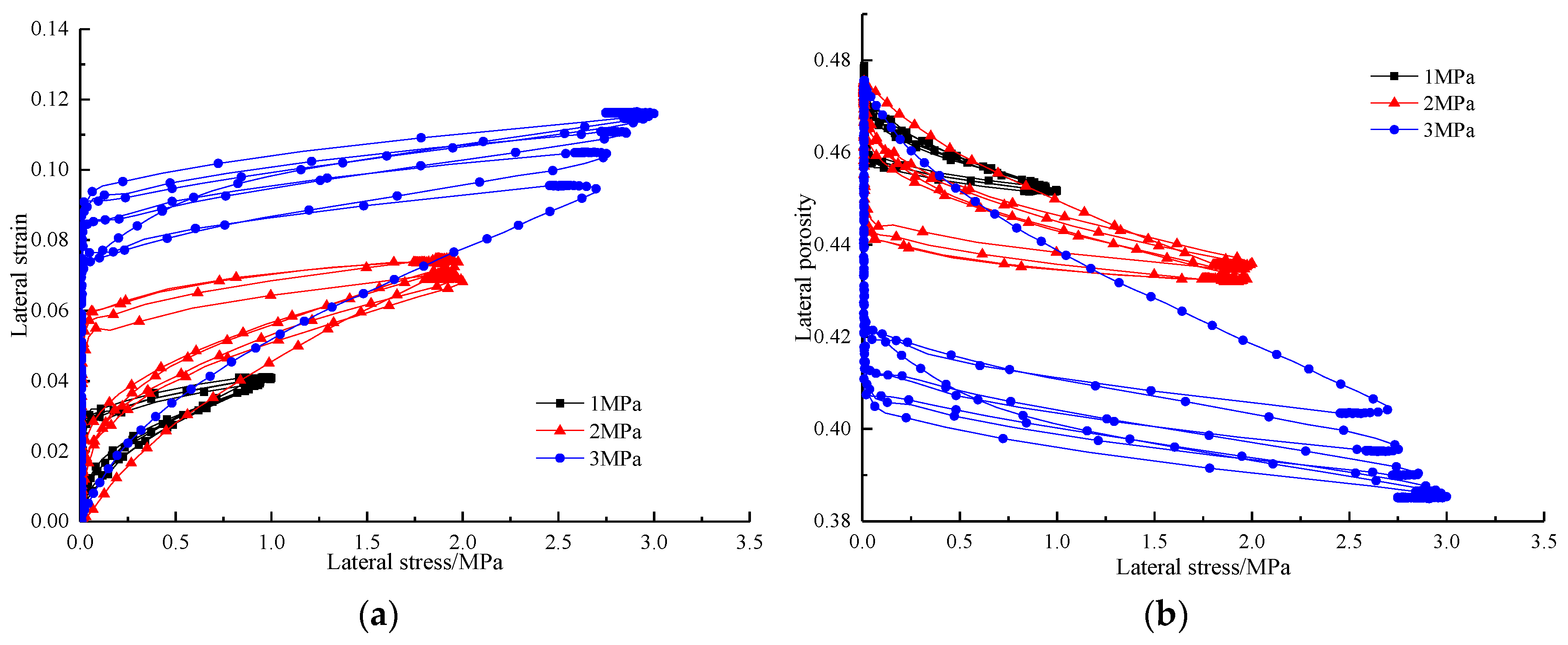
In accordance with the test data from the lateral loading tests and the results calculated using Formulae (2) to (4), changes in strain and porosities of the samples under different lateral stresses under lateral load were obtained (
Figure 8).
(1). After the first lateral loading, the increase rate of the lateral strain of the samples was the highest. Then, with an increase in the times of lateral loading, the increase rate of the lateral strain and lateral porosity of the samples constantly decreased. The lateral loading reduced the porosity of the samples, and the anti-deformability was improved greatly.
(2). For samples under higher lateral stress, the reduction in lateral porosity was larger. For instance, the lateral porosity of samples under a lateral stress of 3 MPa decreased by 0.067 from 0.475 to 0.408, while lateral porosities of the samples under lateral stresses of 1 and 2 MPa were reduced by 0.021 and 0.033, separately. This indicates that the samples under a lateral stress of 1 MPa showed smaller lateral deformation under lateral loading, while the lateral deformation of samples under a lateral stress of 3 MPa was greater.
(3). Samples under lower lateral stress presented smaller lateral strain. Three lateral stresses were ranked as 3, 2 and 1 MPa from large to small according to the lateral strain suffered by the samples. For example, under a lateral stress of 1 MPa, the lateral strain in the samples was 0.031, while that at a lateral stress of 3 MPa reached 0.092. The reason is that the higher the lateral stress applied on the samples, the more work is done by the test system on the waste rock. Therefore, under lateral loading, the particles of the samples under a lateral stress of 3 MPa were more easily crushed and could slip and rotate, thus generating greater lateral deformation.
5.2. Impact of Lateral Stress on Axial Strain and Porosity
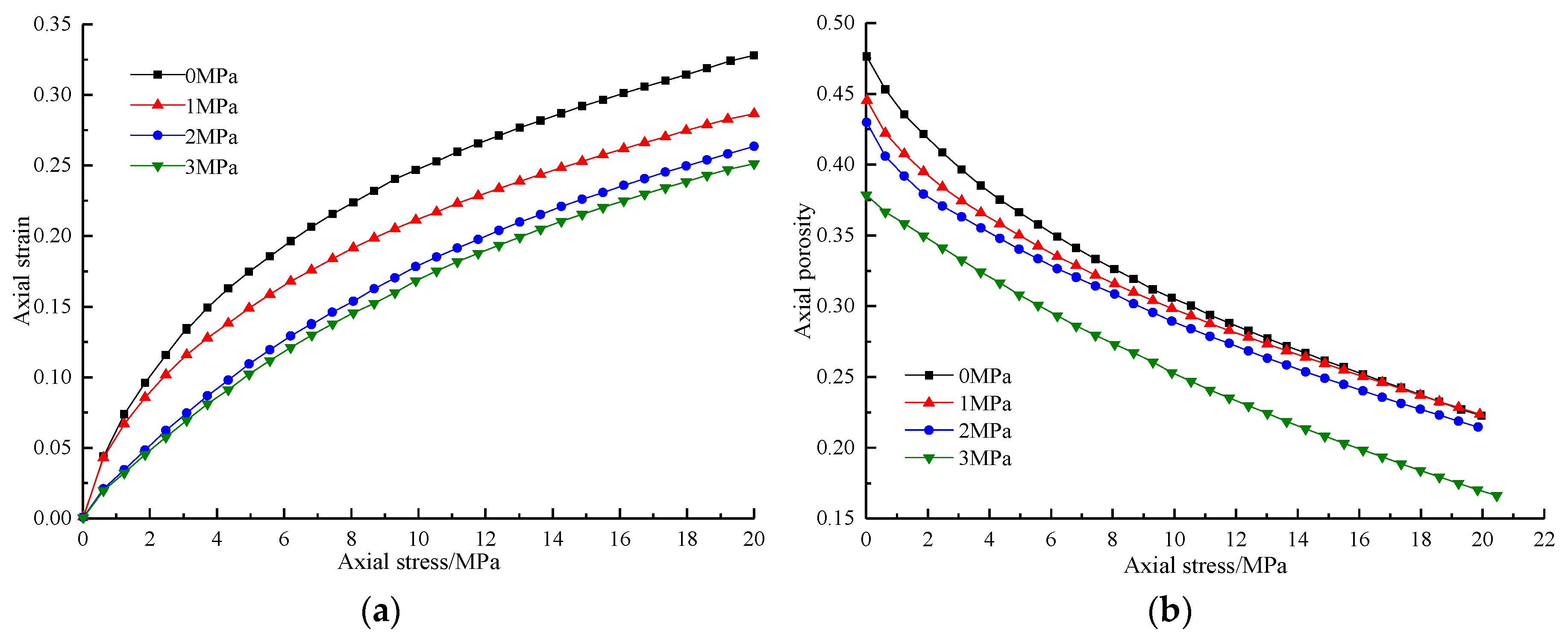
Based on test data obtained under axial loading and results calculated using Formulae (5) to (7), changes in strain and porosity of the samples at different lateral stresses under axial load were obtained (
Figure 9).
(1). The samples under higher lateral stress suffered smaller axial strain. Samples were ranked from large to small in accordance with axial strains at 0, 1, 2 and 3 MPa. For instance, for the samples under a lateral stress of 3 MPa, the axial strain was only 0.251, while that in samples at a lateral stress of 0 MPa reached 0.328. The reason for this is as follows: owing to the lateral deformation of the samples at a lateral stress of 3 MPa being larger, the porosity of waste rocks used for backfilling decreases, while the density thereof increases. Therefore, under axial load, samples under a lateral stress of 3 MPa suffered less axial deformation.
(2). For samples under a lower lateral stress, the reduction in axial porosity was greater. For example, the porosity of samples under a lateral stress of 0 MPa fell from 0.476 to 0.225. For samples under lateral stresses of 1, 2 and 3 MPa, the axial porosities fell by 0.223, 0.216 and 0.211, respectively; these differences can be characterised as significant. This demonstrates that samples at a lateral stress of 0 MPa under axial load showed greater axial deformation, while smaller lateral deformation was found in samples under a lateral stress of 3 MPa.
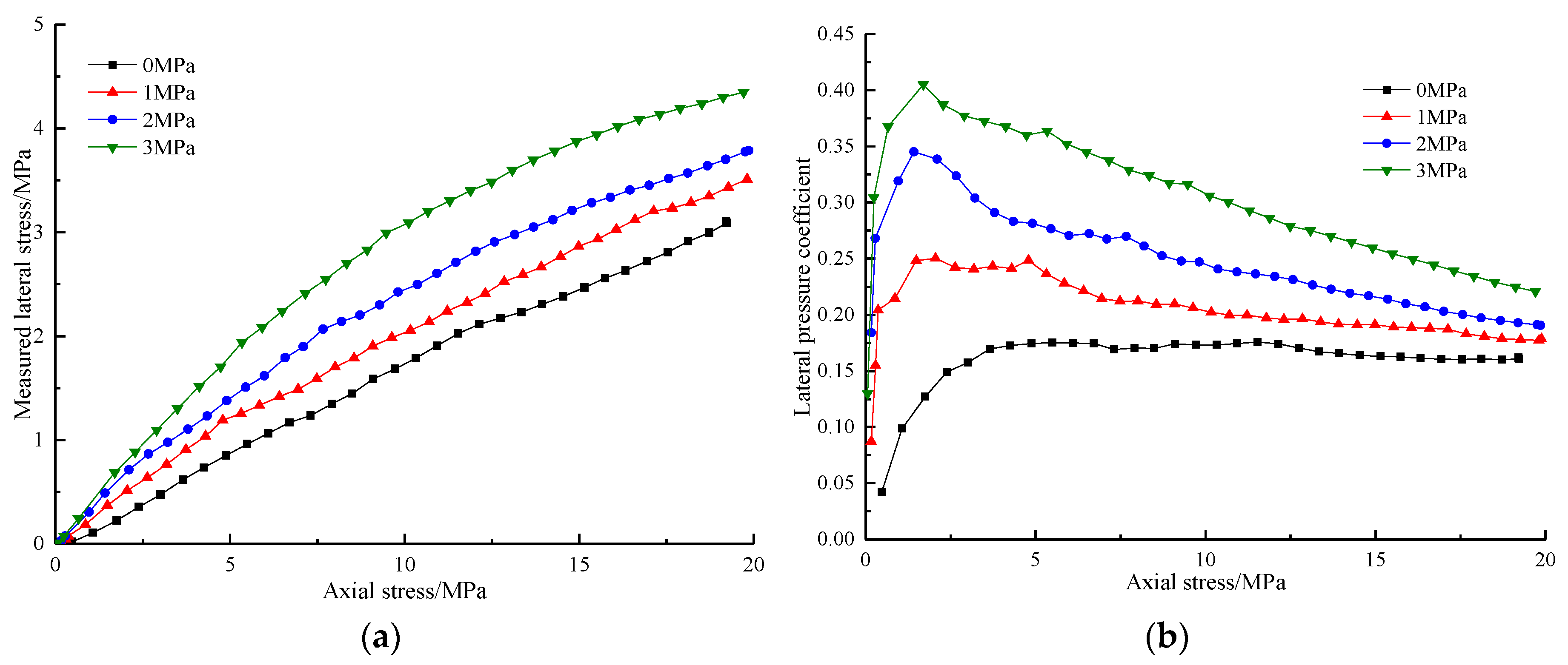
5.3. Changes in Lateral Stress and Lateral Pressure Coefficient Under Axial Load
In accordance with test data for samples under axial load and results calculated using Formula (2), the changes in lateral stresses and lateral pressure coefficients of samples under different lateral stresses and axial loads were attained (
Figure 10). The lateral pressure coefficient of the samples is the ratio of the horizontal stress to vertical stress.
(1). The four lateral stresses were ranked 3, 2, 1 and 0 MPa according to the lateral stress generated under axial load. For instance, the lateral stress at 3 MPa reached 4.35 MPa, while that in samples under a lateral stress of 0 MPa was only 3.12 MPa. This is because the larger lateral deformation of the samples under a lateral stress of 3 MPa reduced the porosity of the samples while increasing their density. Therefore, under axial load, there is no need for axial stress to do work continuously to reduce porosity, thus resulting in the samples under a lateral stress of 3 MPa transferring more stress in the lateral direction than those samples without an applied lateral stress.
(2). The samples under higher lateral stress in lateral loading had a larger lateral pressure coefficient. For instance, the lateral pressure coefficient of the samples under a lateral stress of 3 MPa reached 0.219, while those of samples under lateral stresses of 0, 1 and 2 MPa were 0.161, 0.178 and 0.192, respectively. This shows that the samples under a lateral stress of 3 MPa transferred more stress in the lateral direction, while a smaller stress was applied under a lateral stress of 0 MPa.
(3). The four lateral pressure coefficients first increased and then decreased and eventually seem to have stabilised. This is because the axial loading stress passed to the lateral at first, and when the axial loading stress reached the breakage strength of crushed waste rock, most of the axial stress was used to break the waste rock and reduce the porosity. Finally, with an increase in the axial stress, the porosity was difficult to reduce and the lateral pressure coefficient seems to have stabilised.
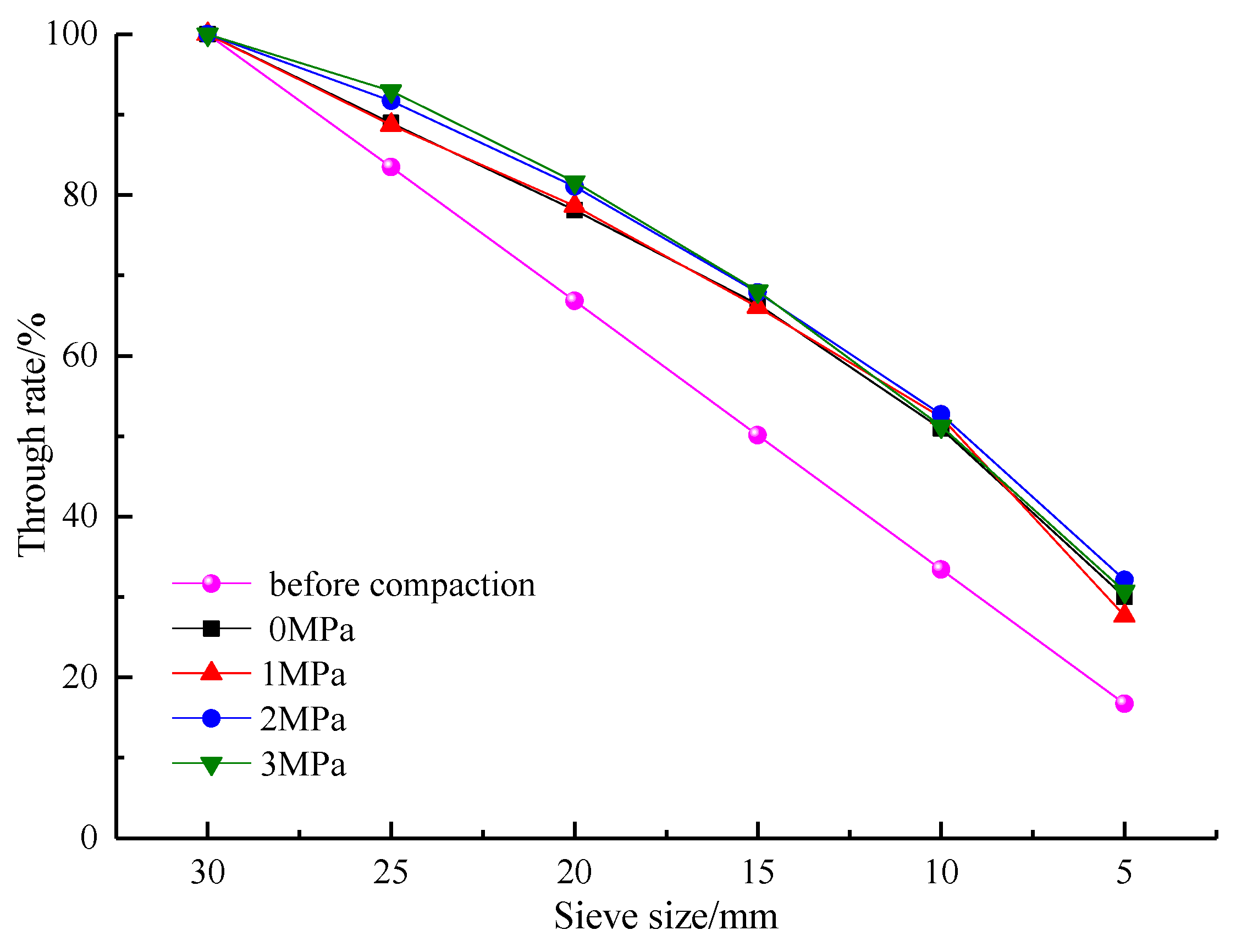
5.4. Changes in Particle Size Before and After Compaction
After completing the compaction test, samples were graded (
Figure 11).
According to the analysis of
Figure 11, after compaction, the particle size distribution of the samples of crushed waste rock under the four lateral stresses all shifted upwards in comparison with those before compaction. This indicates that particles were crushed and the proportion of small particles constantly rose. However, because the applied lateral stress was low and did not reach the crushing strength of the particles, the increase in lateral stress could reduce the porosity of the waste rocks used for backfilling while only slightly affecting the crushing of particles before and after compaction.
6. Conclusions
We investigated the influence of lateral stress on the compaction characteristics of waste rock used for backfilling. By changing the lateral stress on the samples, the effects of lateral stress on lateral strain, axial strain, and porosity were analysed and the changes in lateral compressive stress and lateral pressure coefficient under axial load were tested. Furthermore, the particle size distribution of the samples before and after loading were measured. The following conclusions may be drawn:
(1). The larger the lateral stress on the samples, the greater the decrease in lateral porosity and the higher the lateral strain. For samples under lateral stresses of 1, 2 and 3 MPa, lateral porosities fell by 0.021, 0.033, and 0.067, respectively, and the lateral strain increased from 0.031 under a lateral stress of 1 MPa to 0.092 under a lateral stress of 3 MPa.
(2). The smaller the lateral stress on the samples, the larger the decrease in axial porosity and the higher the axial strain. The porosity of the samples increased from 0.0211 under a lateral stress of 3 MPa to 0.251 under a lateral stress of 0 MPa; corresponding axial strains rose from 0.251 to 0.328.
(3). The greater the lateral stress, the higher the lateral pressure coefficient under axial load. When the lateral stress on the samples in lateral loading was 0 MPa, the lateral stress on samples under axial load was 3.12 MPa and the lateral pressure coefficient was 0.161. When the lateral stress in lateral loading was 3 MPa, the lateral stress and lateral pressure coefficient under axial load reached 4.35 MPa and 0.219, respectively.
(4). With an increase in lateral stress, the porosity of the samples decrease. However, as the lateral stress did not reach the crushing strength of the samples, the increasing lateral stress only slightly affected the extent of particle crushing before and after compaction.


