Article

Research on a Secure and Reliable Runtime Patching Method for Cyber–Physical Systems and Internet of Things Devices

1
State Grid Laboratory of Power Cyber-Security Protection and Monitoring Technology, State Grid Smart Grid Research Institute Co., Ltd., Nanjing 210003, China
2
Department of Electronic Engineering, Tsinghua University, Beijing 100190, China
*
Authors to whom correspondence should be addressed.
Symmetry 2025, 17(7), 983; https://doi.org/10.3390/sym17070983 (registering DOI)
Submission received: 23 May 2025 / Revised: 12 June 2025 / Accepted: 19 June 2025 / Published: 21 June 2025
(This article belongs to the Section Computer)

Abstract

:
Recent advances in technologies such as blockchain, the Internet of Things (IoT), Cyber–Physical Systems (CPSs), and the Industrial Internet of Things (IIoT) have driven the digitalization and intelligent transformation of modern industries. However, embedded control devices within power system communication infrastructures have become increasingly susceptible to cyber threats due to escalating software complexity and extensive network exposure. We have seen that symmetric conventional patching techniques—both static and dynamic—often fail to satisfy the stringent requirements of real-time responsiveness and computational efficiency in resource-constrained environments of all kinds of power grids. To address this limitation, we have proposed a hardware-assisted runtime patching framework tailored for embedded systems in critical power system networks. Our method has integrated binary-level vulnerability modeling, execution-trace-driven fault localization, and lightweight patch synthesis, enabling dynamic, in-place code redirection without disrupting ongoing operations. By constructing a system-level instruction flow model, the framework has leveraged on-chip debug registers to deploy patches at runtime, ensuring minimal operational impact. Experimental evaluations within a simulated substation communication architecture have revealed that the proposed approach has reduced patch latency by 92% over static techniques, which are symmetrical in a working way, while incurring less than 3% CPU overhead. This work has offered a scalable and real-time model-driven defense strategy that has enhanced the cyber–physical resilience of embedded systems in modern power systems, contributing new insights into the intersection of runtime security and grid infrastructure reliability.

1. Introduction

With the rapid progression of technologies such as blockchain [1,2], Cyber–Physical Systems (CPSs) [2,3], the Internet of Things (IoT) [3,4], and the Industrial Internet of Things (IIoT) [4], these have appeared as central forces motivating digitalization, networking, and the intelligent progression through numerous industries. This revolution has not only boosted operational effectiveness, but it also acts as a promoter for broader social advancement [5,6,7,8]. Furthermore, the incorporation of blockchain with IoT and blockchain-based IIoT [8] is vital in safeguarding data security [8,9,10,11] and transparency due to its distributed ledger technology and tamper-resistant characteristics [8,9,10,11]. In the domain of IoT, CPS security, and botnet detection, numerous studies have explored innovative approaches to address the challenges posed by evolving cyber threats.
Embedded systems form the operational backbone of modern power infrastructures, supporting critical functions in smart substations, edge controllers, and renewable integration systems [12]. However, their increasing connectivity within industrial power networks has significantly expanded the system attack surface. Recent ICS-CERT reports have revealed that over 68% of industrial control systems—including those deployed in power automation environments—contain exploitable vulnerabilities [13]. These security flaws enable sophisticated cyberattacks, ranging from data exfiltration to direct manipulation of grid operations, potentially causing financial losses exceeding 10 million per incident in mission-critical scenarios [14,15]. This reality has underscored the urgent need for lightweight, real-time, and robust runtime protection strategies tailored for embedded devices in next-generation power systems.
Existing remediation strategies adopt either static or dynamic approaches. Static patching [16] requires complete system downtime for firmware replacement, while dynamic methods [17] introduce substantial runtime overhead (typically 15–20% CPU utilization). Christian Niesler [16] et al. proposed a framework called HERA to hot-patch embedded real-time systems without violating real-time constraints. Both prove impractical for embedded devices constrained by the following:
1. High risk of service interruption: The static patching method requires complete downtime to complete a vulnerability repair, and for mission-critical scenarios (e.g., medical monitoring, industrial production [18], etc.) running in embedded devices, service interruptions may lead to serious consequences, which is not conducive to system continuity assurance.
2. High resource overhead: Dynamic patching approaches are usually designed for high-performance devices, and it is difficult to support the operation of complex patches with embedded devices due to resource constraints (e.g., limited memory, storage, and computational power). In addition, dynamic patching may introduce additional computation and storage overheads, further affecting device performance.
To address the above limitations, we have proposed a hot-patching-based vulnerability remediation method for embedded devices, which is based on the built-in functionality of the hardware to perform the hot-patching of embedded systems, retaining strict real-time constraints while minimizing additional resource usage [19]. The method consists of four steps: vulnerability identification, vulnerability localization, patch preparation, and patch switching. The key idea is to replace instructions at runtime using an on-board debugging unit, which is readily available on commercial off-the-shelf processors. The methodology has enhanced the detection-based hotfixing approach without the need for binary detection and other software layers.
The main contributions of this paper are as follows:
  • We have proposed a customized remediation framework to meet the asymmetric or heterogeneous needs of embedded systems. We have designed a four-step remediation process (vulnerability identification, vulnerability localization, patch preparation, and patch switching) tailored to the characteristics of embedded devices, which enhances the detection-based hotfixing approach to avoid relying on binary detection and other software layers and improves the accuracy and adaptability of the patches.
  • To address service interruptions caused by static patching, we have proposed a lightweight runtime hot-patching method tailored for embedded devices. Although hot patching is a known concept, its application in resource-constrained environments, like industrial embedded systems, remains challenging. Our approach has avoided system downtime by leveraging built-in hardware debug features, ensuring low overhead and strict real-time performance. This has enabled safe and efficient patching in mission-critical scenarios where service continuity is essential.
  • In order to overcome the high overhead of dynamic patching, the framework uses on-board debugging units to dynamically replace instructions at runtime, which has reduced resource consumption during the repair process majorly while maintaining the real-time nature of the system. This method assumes the availability of on-chip debug components, like FPB and DWT, which are widely supported by Cortex-M microcontrollers; thus, its applicability is focused on embedded platforms with such hardware features.
  • The experimental results have shown that the hot-patch-based vulnerability repair method proposed here has performed well in embedded device vulnerability repair, has effectively reduced system downtime and service interruption, and has provided strong support for the stability and availability of these kinds of symmetric systems. Through in-depth analysis and optimization, we have provided an innovative and efficient solution for the security maintenance of embedded devices, which has important theoretical significance and practical value.
This paper is organized as follows: Section 2 reviews the related works on runtime patching in embedded systems. Section 3 presents the proposed methodology, including vulnerability identification, localization, patch preparation, and switching. Section 4 describes the experimental setup and discusses the evaluation results. Section 5 concludes this paper and describes the directions for future works.

2. Related Works

With the continuous development of Internet technology, the traditional patching method that requires constant recompilation and deployment no longer meets the rapid iteration needs of enterprises. In order to solve the problems and security vulnerabilities that may occur during the actual use of software products, and to improve the reliability and security of the system through real-time updating and repairing, as well as to reduce maintenance costs and improve development efficiency, academia and the industry have turned their attention to hot patching. Payer [18] et al. introduced a dynamic software update mechanism that dynamically applies security patches without modifying the binary application. This mechanism combines sandboxing techniques to protect system integrity and improves application availability through a dynamic update mechanism. Holmbacka [19] et al. introduced a lightweight runtime update framework that replaces C-based software in embedded systems without interrupting the system. Jiang Wen [20] et al. proposed a hot-patching technique for software maintenance in the VXWORKS 7 operating system using ClearCase and ICP-CI to produce hot-patches, introducing the advantages of real-time fixes and improved system reliability. HERA utilizes the hardware features of commercial Cortex-M microcontrollers to perform hot patching without any hardware modifications, preserving hard real-time constraints while keeping additional resource usage to a minimum. Zhou M [21] et al. proposed a reliable real-time patching framework, called RLPatch, which allows for the closed-source patching of Programmable Logic Controllers (PLCs) without the need to access the source code. Yi He [22] et al. proposed RapidPatch, which consists of a patch-generation module for generating device-specific patches from eBPF patches and configurations and a patch validation module that checks for malicious behaviors in the patches. Mingquan Wang [23] discussed remote hot deployment technology based on SpringBoot. Identifying patch correctness in test-based program repair was shown in [24]. The principles of Devtools and Arthas, two Java implementations of hot deployment, were described in detail, including hot deployment methods based on ClassLoader and Java Agent mechanisms. This framework is based on FreeRTOS and has added mechanisms for dynamically linking and relinking FreeRTOS tasks to the system [25]. Ramaswamy [26] et al. presented a new hotfix framework, Katana, that provides an effective hotfix solution for ELF binaries, which is important for improving software security and reliability.
Naeem et al. [27] proposed a hierarchical distributed proxy model based on deep learning, which utilizes the capabilities of deep neural networks and combines a distributed proxy architecture to achieve efficient detection and risk assessment of network intrusions. Chen [28] et al. proposed a scheme that provides real-time update capabilities through virtualization, allowing patches and upgrades to be applied at any time without the need to be in a silent state. The advantages of this approach are its wide range of applications and good portability, which makes it particularly suitable for integration into general-purpose virtualized systems. Altekar [29] et al. explored the development and application of the OPUS tool, which is capable of dynamically applying fixes to C programs, especially in safety-critical applications that require frequent updates.
While the above hot-patch-based patching approaches have addressed the hardware architecture constraints of IoT devices and have satisfied the embedded device real-time problem, it is difficult to generate patches based on different types of devices due to the fact that vendors have a variety of types of fragmented devices, which hamper the installation of patches on devices that require real-time [30] and high availability. In view of the above, we have performed hot patching of embedded systems based on the built-in functionality of the hardware, which has preserved strict real-time constraints while addressing compatibility issues.

3. Methodology

The hot-patch-based vulnerability patching method is a non-disruptive deployment update method for embedded devices based on an ARM processor with a built-in debugging function. Compared to prior runtime patching frameworks (e.g., HERA, RapidPatch), our method introduces three key innovations tailored to real-time embedded systems: (1) a semantics-aware patch scheduling strategy based on execution context; (2) a hardware-level remapping mechanism leveraging FPB atomicity; and (3) a lightweight patch dispatcher design enabling safe control redirection from ROM to RAM without modifying application binaries. These innovations are integrated across the four-stage remediation workflow and are highlighted accordingly in the subsequent subsections.
Figure 1 illustrates the detailed process of inserting a jump instruction via the on-chip debugging unit. Specifically, it shows how the system first identifies the instruction to be redirected, configures a hardware breakpoint at that address, and utilizes a patch dispatcher in ROM to handle the jump-to-patch code located in RAM. The intermediate dispatcher mechanism is necessary because of platform constraints that prevent direct jumps from ROM to RAM. This redirection ensures uninterrupted execution by seamlessly transitioning control flow between original and patched code segments during runtime.

3.1. Vulnerability Identification

To enable structured vulnerability identification, the latest update report released by the PLC vendor is first analyzed to extract key vulnerability information. Let the report set be denoted as R = r 1 , r 2 , , r n . Named Entity Recognition (NER) is applied via a model F N E R   to extract entities containing vulnerability ID, type, affected firmware version, target controller, logic instructions, and trigger conditions:
E = F N E R R = id i , type i , version i , ctrl i , logic i , trig i i = 1 m
This structured entity set provides a solid foundation for subsequent analysis, especially for identifying Major Non-Recoverable Failure (MNRF) vulnerabilities, which may lead to memory corruption and control failures with severe safety implications. Named entity extraction techniques for software security and industrial reports have proven effective in prior work [3].
After initial extraction, the entity set E is filtered and completed. Entities that satisfy the completeness condition is _ complete e i are retained, while incomplete ones are supplemented using expert knowledge or rule-based inference F manual ( ) , resulting in the completed entity set:
E = e i E   is _ complete   e i = T r u e F manual   ( E )
This step ensures the semantic integrity and logical sufficiency of the vulnerability data, preventing the propagation of errors in later stages. Rule-based completion and hybrid manual heuristics are common in ensuring semantic completeness and logical sufficiency [4,5].
Next, vulnerable logic instructions are extracted by mapping each vulnerability to its associated control behavior using the vendor-provided PLC programming manual M PLC . A mapping function M map   is applied to obtain the instruction set:
L = M map E , M PLC
These instructions typically include operations for data processing, input response, and loop control, and they are critical for identifying logic-level vulnerabilities that could affect system reliability [12].
Finally, based on the instruction set L , trigger conditions are identified by focusing on Arabic numerals (e.g., fixed parameters) and programming logic keywords (e.g., WHILE, IF). A trigger extraction function F trigger is defined to produce a set of conditions expressed as:
T = F trigger ( L ) = t i n k N , k j K
where n k N denotes fixed numeric parameters used in trigger conditions, k j K represents control-flow keywords embedded in the vulnerable logic, and K is the predefined set of logic keywords used for trigger pattern recognition.
These logic-level triggers are crucial for static analysis and vulnerability activation modeling, as widely discussed in control flow graph-based methods [6].

3.2. Vulnerability Localization

Vulnerability localization consist of four main steps: inserting vulnerable logic instructions, setting observation points, tracing code access paths, and recording vulnerability metadata.
First, let the control program of a Programmable Logic Controller (PLC) be denoted as p , composed of a sequence of logic instructions I 1 , I 2 , , I n . A specially crafted vulnerable instruction I v is injected, such that:
I v = I n s e r t L v , V t a g
where L v denotes the logical location within the program and V t a g is a controller-specific label that marks this instruction as vulnerable. This insertion serves to emulate or trigger latent vulnerabilities exploitable via unauthorized control actions or data manipulation [18]. Additionally, logic flag values f { 0,1 } can be set to modulate control flows for conditional execution, providing a lightweight mechanism to activate I v .
Second, a watchpoint W is placed at the address of I v using the PLC’s internal debugging mechanism:
W = S e t W a t c h p o i n t A d d r I v
This allows the debugger to intercept and monitor any access to I v during execution. Depending on the platform, W may be established statically in source code or injected dynamically at runtime [18].
Third, let T = p 1 , p 2 , , p m represent the set of execution traces reaching I v . When the PLC program executes and hits the watchpoint W , the debugger logs each access path p i T , such that:
p i = T r a c e P a t h I start I v
These paths provide essential context for identifying the control flow segments that interact with the vulnerability.
Finally, all extracted vulnerability information is documented into a remapping table V map , recording tuples of the form:
V map = F W i , V I D i , I l , A d d r I v
where F W i is the firmware version, V I D i is the unique vulnerability ID, I v is the logic instruction, and A d d r I v is the entry point. This serves as a reference for future remediation or automated patching processes.

3.3. Patch Preparation

Patch preparation involves three main stages: (1) integrity verification of externally received patches, (2) parsing of patch code and metadata, and (3) static analysis of patch content.
Let a received patch be denoted as P ext , which includes the patch code C patch and associated meta-information M patch . Upon reception, the system computes a cryptographic hash H P ext and compares it to the expected hash H ref :
Verify P ext = A c c e p t e d ,   i f   H P ext = H ref R e j e c t e d , o t h e r w i s e  
This ensures the integrity and authenticity of P ext , mitigating the risk of tampered or malicious patches.
Next, the patch is parsed to extract both C patch and M patch ,
M patch = S patch , L insert
where S patch denotes the patch size (in bytes) and L insert represents the code insertion location within the original program P orig . Here, Δ C denotes the structural delta between the original vulnerable code and the generated patch. It is defined as a tuple:
Δ C = C add , C del , C mod
where C add represents newly introduced instructions (e.g., memory sanitization calls), C del represents instructions removed to eliminate vulnerable behaviors, and C mod represents modified logic (e.g., condition rewriting, pointer constraints).
This delta-based representation enables fine-grained tracking of code transformation and provides the basis for static analysis and rollback control in subsequent verification.
A precise determination of L insert is essential to apply Δ C correctly; any deviation could lead to functional failures or latent bugs [31].
Finally, a static analysis function C patch is applied using tools such as PC-Lint and Coverity Prevent [3]. To ensure that the generated patch C patch is not only syntactically correct but also secure and standards-compliant, we incorporated a static evaluation phase prior to deployment. This process is formalized as a composed static check function:
Check static C patch   Assessment   Report  
Unlike simple syntax validation, this step evaluates the patch from multiple dimensions. First, an abstract syntax tree (AST) parser verifies whether C patch adheres to the grammar and structural integrity of the target language. Then, a semantic analyzer scans the code to detect the usage of potentially dangerous functions (e.g., strcpy, malloc without size checks), ensuring the absence of known vulnerability patterns.
Furthermore, the function checks the patch against a set of predefined coding rules R , such as MISRA-C or device-specific constraints, to avoid violations in memory access, pointer arithmetic, or exception handling. The result is a structured report:
Assessment   Report   =   ( Syntax _ OK ,   Safe _ APIs ,   Guideline _ Score ,   Risk _ Level )
Each component reflects a critical facet of patch quality. For example, if Syntax_OK = True and Risk_Level ≤ Medium, the patch is qualified for further integration; otherwise, it is flagged for manual revision. This formalized evaluation provides assurance that C patch will not introduce additional vulnerabilities or deviate from system policies. It also supports automated decision-making in the patch submission pipeline.
This step ensures that C patch conforms to syntax rules, complies with coding standards, avoids the use of dangerous functions, and does not introduce additional vulnerabilities. It enables a preemptive quality and security assessment before the patch is committed to P orig .
While static analysis helped to ensure the basic correctness of patch code, it becomes increasingly challenging when dealing with larger patch sizes and more complex vulnerabilities. In such cases, the patch may span multiple functions or affect control logic deeply embedded in the execution flow, which increases the risk of inconsistent behavior or unintended side effects after deployment. Moreover, larger patches demand more memory and processing resources, which may exceed the real-time and resource constraints of embedded systems. Therefore, future extensions of our framework should consider incorporating patch-size-aware verification strategies and complexity-adaptive scheduling mechanisms to enhance robustness under these challenging conditions.
As the size of the patch increases and the vulnerability becomes more complex—spanning multiple functions or involving intricate control logic—the verification and deployment process becomes significantly more challenging. Larger patches not only increase memory usage and parsing overhead but also raise the risk of unintended behavior due to deep interdependencies. Figure 2 has illustrated a conceptual example of how patch size and control complexity influence patch injection accuracy. To address these concerns, our framework may be extended in future work with patch-size-aware static analysis and complexity-adaptive patch schedulers.

3.4. Patch Switching

Patch switching includes copying the patch code to the patch preselection area of the random access memory (RAM) and adding the contents of the meta-information to the corresponding data structure; adding the patch task to the scheduling program and configuring the jump instruction; updating the program to notify the hardware of the activation of the patch through an atomic instruction; monitoring the instructions executed by the CPU, comparing the current memory location of the CPU with the insertion point of the jump instruction, and triggering an interrupt when they are consistent; jumping to the patch code through the jump instruction; and returning to and executing the patch code when it is finished, as shown in Figure 3.

3.4.1. Debugging Unit FPB Configuration

Here, we copy the patch code to the patch preselection area of RAM and add the contents of the meta-information to the corresponding data structure [32], i.e., the debug unit FPB (Flexible Priority Blocker) configuration. The proposed method relies on on-chip debug units, such as FPB (Flash Patch and Breakpoint) and DWT (Data Watchpoint and Trace), which are commonly available in ARM Cortex-M series microcontrollers. Devices lacking such hardware features (e.g., ultra-low-end MCUs without debug support) are not within the applicable scope of this framework. The FPB unit configuration requires a C library to be executed, and this library contains the following functions:
  • The fpb_Init function is responsible for initializing the FPB unit, ensuring that the FPB unit has been loaded correctly, and preparing for subsequent task scheduling and priority management.
  • The fpb_enable function is used to set the FPB unit to be enabled and disabled; if not set, the device will ignore any breakpoints that have been configured and enabled.
  • Let the patch code be denoted as P , and let a d d r insert   represent the address where the jump instruction will be injected. We define a mapping function:
F map   P , a d d r insert   J
where J is the jump instruction calculated from the patch offset:
J = J U M P a d d r insert   a d d r P
and a d d r P is the memory location where patch P is loaded. This function writes J to a register using atomic operations, ensuring atomicity of control flow redirection.
  • We define a patch loading function:
F load   P , a d d r P : ( P , A )   RAM
where A is the address space and F load copies patch P into the predefined patch region of RAM at location a d d r P . The loading process updates a dispatcher table D , used for runtime redirection:
D a d d r insert a d d r P
Unlike existing hot-patching solutions that rely on runtime binary rewriting or custom kernels, our use of the hardware-native FPB configuration (i.e., F map , F load ) provides minimal-intrusion patch injection suitable for resource-constrained microcontrollers. This FPB-based abstraction is one of the core contributions of this work.

3.4.2. Add Patch Tasks to the Scheduler and Configure Jump Instructions

The introduction of dynamic patching technology requires extensions to handle patch tasks, including loading, execution, and subsequent maintenance work.
In the patching process, jump instructions must be configured and patch execution tasks scheduled. We defined a patch scheduling function as follows:
F sched P , a d d r insert ,   meta T
where P is the patch code, a d d r insert is the redirection point in the program, meta represents patch metadata (e.g., priority, type), and T is the patch task object added to the runtime scheduler.
To redirect execution, a jump instruction J is injected via the remapping function:
F jmp   a d d r insert   , a d d r P = J U M P a d d r insert   a d d r P
which is stored in the FPB configuration table F F P B .

3.4.3. The Update Program Notifies the Hardware to Activate the Patch Through Atomic Instructions

The update program can activate patches efficiently in real time through atomic instructions, which, at the hardware level, usually involves cache coherence protection and prohibiting instruction reordering to ensure data consistency and correctness during the patching process. To ensure correctness during patch activation, an atomic write is used to trigger the patch. We define:
F atomic : ( r e g , v a l )   MEM
where reg is a hardware control register and val is the flag to activate the patch.
This write ensures cache coherence and instruction consistency:
MEM   [ reg ]   val ,   with : barrier memory   ( )
Patch activation is now visible to the CPU only after:
  flush cache ( ) ;   sync instr ( )

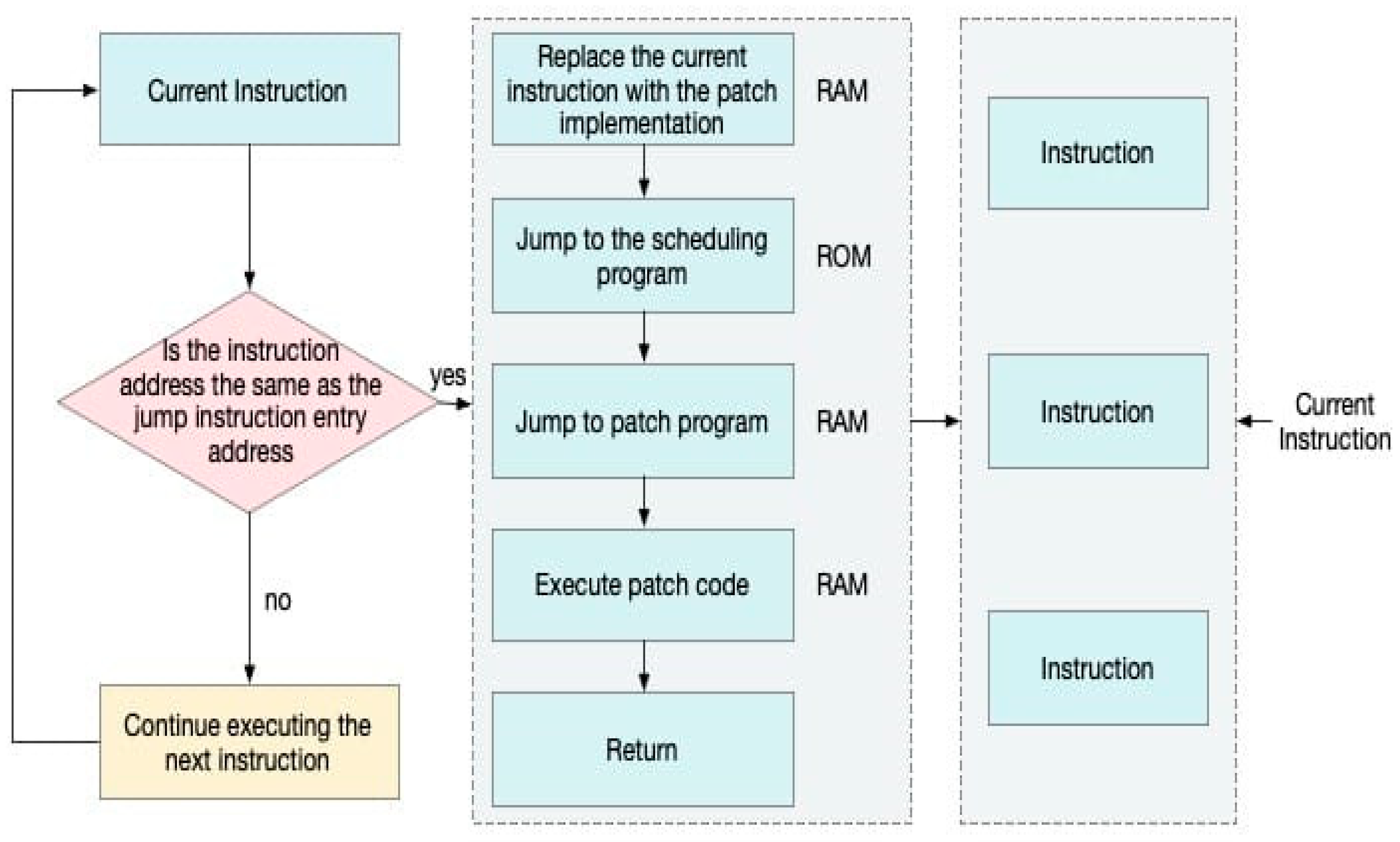
3.4.4. Monitor the Instructions Executed by the CPU

To realize atomic switching, hardware breakpoints can be used to enable patching. Hardware breakpoints are a special debugging feature [33] that can be set to trigger a patch switch. A patch switch is triggered when the CPU executes to the set hardware breakpoint. Since hardware breakpoints are atomic instructions, the atomicity of a patch switch can be guaranteed. The process of patch switching is a sophisticated and complex operation that involves CPU instruction monitoring and interrupt handling. In this process, the CPU plays a crucial role, continuously monitoring all instructions being executed. Whenever the CPU executes an instruction, it compares the current instruction address with a preset insertion point for jump instructions. This comparison process is extremely critical. If the CPU finds an exact match between the current instruction address and the jump instruction insertion point, it immediately triggers an interrupt to pause the current instruction flow. This is an exact breakpoint hit, meaning that a patch switch is required. At this point, the CPU stops executing the current instruction, and by writing pre-configured data to the specified hardware registers, it can realize the insertion of the jump instruction and switch to patch loading and replacement. If it does not match, then the execution of the next instruction continues.
During runtime, the CPU continuously executes instruction streams at a program counter address p c t A , where A is the virtual address space. The core mechanism involves comparing the current instruction pointer p c t with a predefined jump insertion point a d d r insert . Formally, a breakpoint trigger function is defined as:
F b p p c t = 1 , i f   p c t = a d d r insert   F P B enabled   = 1 0 , o t h e r w i s e  
This function returns 1 when the program counter matches the configured breakpoint, indicating the patch switch should be triggered. Upon activation, an interrupt is issued to pause the normal instruction flow. The system then invokes a dispatcher function F dispatcher   to determine the redirection target:
p c t + 1 F dispatcher addr insert = a d d r P
where a d d r P is the memory address, and the patch code resides in RAM.
This redirection maintains execution consistency by preserving context C t before the jump and restoring it after patch execution. Specifically, after the patch handler completes, the dispatcher resumes control at the original return point addr return :
p c t + 2 addr return , where addr return = p c t + δ
where δ represents the offset to the next instruction beyond the patched segment.
This monitoring and switching process is fully transparent to upper software layers. It guarantees atomicity through hardware-supported breakpoints and ensures that the patch application has not created any observable delay or inconsistency from the perspective of the application logic.
While instruction monitoring via hardware breakpoints has been explored before, our dispatcher-enhanced redirection logic—formalized in F dispatcher —provides a generalized patch transition model that supports both inline and out-of-band execution. This bridging mechanism contributes a novel formulation for seamless code switching in constrained memory architectures.

3.4.5. Jump to Patch Code by Jump Instruction

As illustrated in Figure 1, once a breakpoint is triggered, the CPU immediately replaces the current instruction at address A curr with a predefined patch table entry E patch . Each E patch can be represented as:
E patch = I jmp , A target
where I jmp is the jump instruction and A target is the jump destination address. The CPU fetches and executes I jmp from E patch , thereby redirecting control flow to A target and realizing seamless instruction flow redirection.
Patch injection into the original code C oril is achieved by configuring two key positions: the jump instruction insertion point A insert   j m p C oril , where I jmp is inserted, and the branch return point A branch , which denotes the resume point in C oril after patch execution.
Thus, a redirection mechanism is constructed, such that:
C orig A insert j m p C patch C orig A branch
However, the platform in use imposes a constraint: direct jumping from ROM to RAM is not supported, i.e.,
J U M P ROM RAM I S A platform
To address this, an intermediate ROM region called the jump_section is introduced. This section acts as a patch dispatcher:
jump _ section : A rom A ram
It receives the control from A insert jmp and forwards it to the patch code residing in RAM. Let D jmp denote this dispatcher logic; then, the complete control flow becomes:
C orig A insert j m p D jmp A rom C patch A ram C orig A branch
This mechanism effectively evades the hardware limitation and enables flexible patch redirection from ROM to RAM, preserving execution integrity while enabling runtime modification.

3.4.6. Execute Patch Code

When the CPU finishes executing the patch code in RAM, it returns to the original instruction stream and continues to execute the next instruction. This switching process is transparent to the user, who hardly feels any interruption or delay. This is the essence of patch switching, which enables fast replacement and execution of specific instructions without affecting the overall operation of the system.

4. Experiments

4.1. Experimental Environment

To facilitate reproducibility and clarity, Table 1 is expanded to include more granular details of the experimental setup. The CPU model used was an Intel Core i7-10870H with a base frequency of 2.2 GHz and eight cores. The experiments were conducted on Ubuntu 20.04 LTS with a kernel version of 5.15.0. The GDB debugger was version 10.1, and Eclipse IDE 2021-09 was configured with GCC 9.4.0. All network communication was monitored using Wireshark 3.4.8, and traffic generation utilized Scapy 2.4.5 in a VMware Workstation Pro virtualized environment. These settings ensured consistency across the executions and provided a realistic simulation of embedded runtime environments.

4.2. Datasets

In this study, vulnerability fixing datasets, as shown in Table 2, were used, with each vulnerability corresponding to a specific component and description, as well as a corresponding filter. The dataset used in this study consisted of five known vulnerabilities in the PicoTCP stack, each representing a unique class of logic or memory-handling flaws. Each vulnerability entry in Table 2 includes a CVE identifier, affected submodule, and a brief description. CVE-2020-17441 involves improper validation of IPv6 payload length fields, while CVE-2020-17445 pertains to insufficient bound checking of option length parameters. The selected vulnerabilities reflect real-world embedded network stack issues and were chosen to validate the generalizability and effectiveness of the proposed runtime patching framework across control logic, memory access, and protocol parsing layers.

4.3. Experiment and Result Analysis

4.3.1. Vulnerability Fixing Time Comparison Experiment and Result Analysis

In the vulnerability remediation process for embedded devices, remediation time is a key metric. In order to evaluate the advantages of hot-patching methods in terms of fixing time, we conducted comparative experiments covering three cases: no patch added, the traditional patching method, and the hot-patching method.
In this experiment, the “no patch” scenario denotes a baseline where the system continues execution despite known vulnerabilities, mimicking legacy systems lacking OTA patch support. The “traditional” method represents the common firmware update process involving full image replacement and reboot, typically seen in embedded RTOS environments.
As shown in Figure 4, the hot-patching approach has significantly shorter remediation times than the traditional update approach for all the tested vulnerability IDs. For instance, the fixing time for CVE-2020-17441 was reduced from 960 ms (traditional patching) to only 74 ms using hot patching. Symmetrically, CVE-2020-17442 showed a reduction from 875 ms to 81 ms, and CVE-2020-17445 decreased from 1012 ms to 69 ms, indicating a consistent reduction rate of over 90% across the cases. This significant improvement demonstrates the effectiveness of the proposed method in reducing system downtime and enhancing real-time responsiveness. On average, the hot-patching method achieved a 92.4% reduction in patching latency compared to static patching techniques.
In addition to per-vulnerability comparisons, we performed a statistical summary of fixing time across all five tested vulnerabilities. As shown in Figure 5, the hot-patching method yielded a mean latency of 73.4 ms with a standard deviation of 4.2 ms, substantially lower than the traditional patching method (mean: 955.4 ms, std: 48.4 ms) and the no-patch baseline (mean: 1506.0 ms, std: 71.3 ms). This analysis reinforces the consistency and efficiency of the hot-patching approach under varying scenarios.

4.3.2. Vulnerability Repair Success Rate Comparison Experiment and Result Analysis

In order to further evaluate the effectiveness of different restoration methods, we compared the performance of different methods in terms of restoration success rate. The experimental results are shown in Figure 6.
Although traditional patching theoretically ensures vulnerability removal, its success rate in our testbed was affected by memory limitations and bootloader inconsistencies, which led to failed or partial deployments in some runs. This highlights a practical challenge in static firmware-based remediation under constrained hardware.
As shown in Figure 6, for all five tested vulnerabilities, the hot-patching method achieved a 100% fix success rate, whereas the traditional method only succeeded in three out of five cases, with success rates ranging from 80% to 95%.
These results confirm the supremacy of the hot-patching strategy in achieving complete remediation coverage compared to conventional methods. Traditional update methods may not be able to completely fix the vulnerabilities in some cases, allowing security risks to remain in the system. The hotfix method, on the other hand, ensured that every vulnerability is completely fixed through a dynamic repair mechanism.
As shown in Figure 7, the hot-patching method consistently achieved a 100% fix success rate across all five vulnerabilities, with zero variance. In contrast, the traditional patching approach exhibited a lower average success rate of 88.6% with a standard deviation of 5.3%, while the no-patch condition naturally recorded a 0% success rate. These findings further validate the reliability and completeness of the proposed method.

4.3.3. System Stability Comparison Experiment and Result Analysis

In order to evaluate the impact of different repair methods on system stability, we compared the number of system crashes during the repair process of different methods. The experimental results are shown in Figure 8.
As shown in Figure 8, in terms of the number of system crashes, the hot-patching approach has 0 crashes on most vulnerability IDs, which is significantly lower than the traditional update approach and the approach with no patches added.
The number of system crashes during patching was reduced to zero for all test cases using hot patching, while traditional patching resulted in 1–2 crashes in at least 60% of the cases. The traditional update method may lead to system crashes and service interruptions during the repair process, whereas the hot-patching method, due to its feature of not requiring a system restart, enables the system to still operate normally during the repair process, which greatly improves the stability and availability of the system.
Figure 9 has shown the average number of system crashes observed during each patching scenario. The hot-patching method did not crash across any test cases, demonstrating robust runtime safety. Conversely, both the traditional and no-patch methods recorded frequent crashes, with the latter showing the highest instability. These results affirm the operational robustness of our proposed solution.

4.3.4. System Usability Comparison Experiment and Result Analysis

In order to comprehensively evaluate the impact of different vulnerability remediation methods on system availability, we compared the system availability after remediating a vulnerability with no patch, the traditional patching method, and the hotfixing method.
System   Availability = 100 % ( Number   of   Crashes × Crash   Penalty )                                                                                                     Repair   Time Maximum   Tolerance   Time × 10 %
We assumed that the crash penalty was 2%. The maximum tolerance time was 2000 μs.
As shown in Figure 10, the hotfix method outperformed both the traditional patching method and the no-patch method in terms of system availability after remediation. For example, after the CVE-2020-17441 vulnerability was fixed, the hotfix method achieved 92% system availability, compared to 87.5% for the traditional patching method and only 60% without adding a patch. In the case of the CVE-2020-17442 vulnerability, the hotfix method had 99.1% system availability, almost a perfect score.
The results of such experiments show that the hot-patching approach is not only effective in fixing vulnerabilities, but it also maximizes system availability and reduces the downtime and impact of the fixing operation. Traditional patching methods may lead to longer system downtime during the repair process, thus affecting the overall system availability. The hotfix method, however, significantly enhances runtime robustness without necessitating a system reboot.

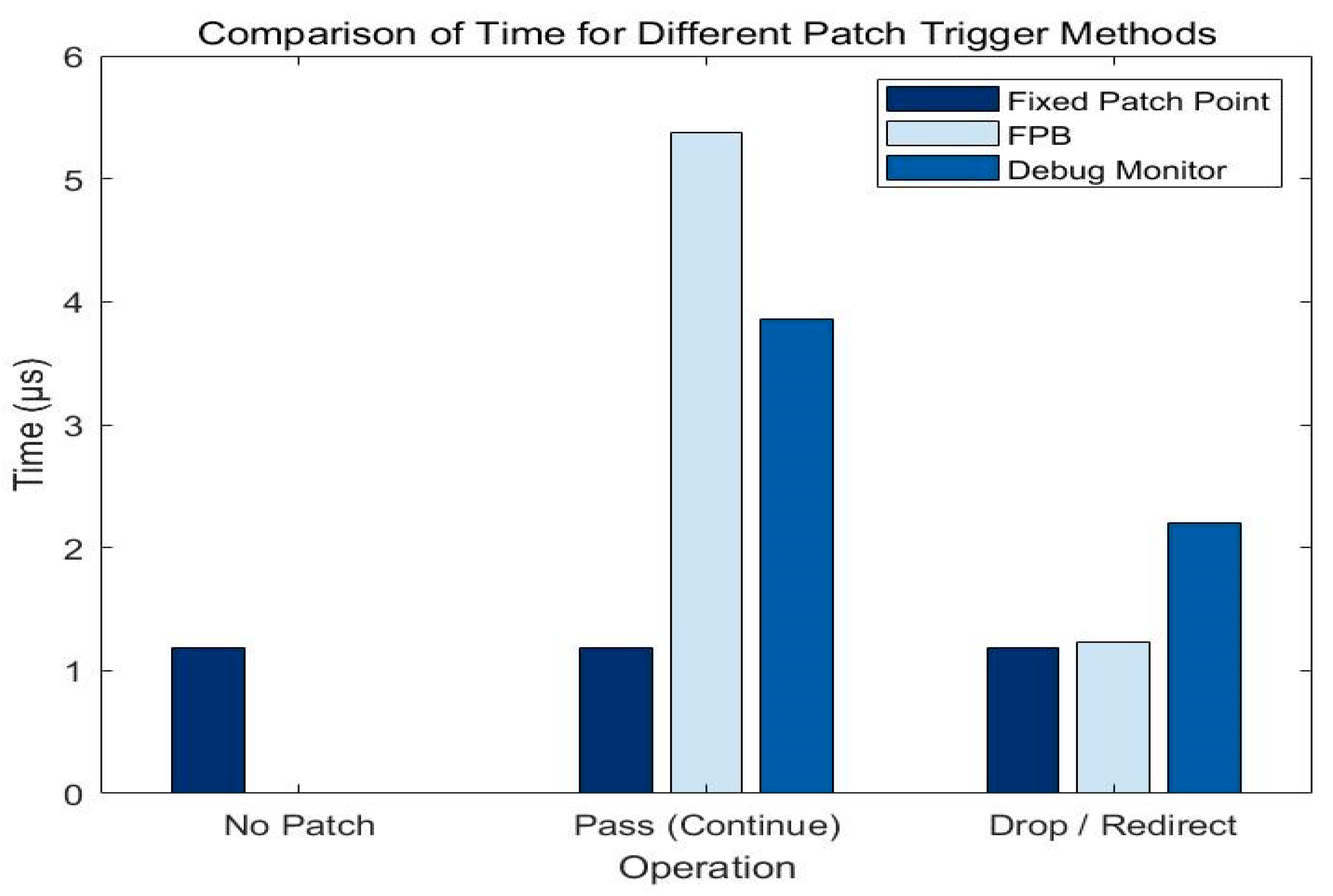
4.3.5. Experiment and Result Analysis of Time and CPU Cycle Required for Different Patch-Triggering Methods

In the experiment of different patch-triggering methods, we compared the CPU cycles and time of Fixed_Patch, FPB, and Debug_Monitor under different operations. The experimental results are shown in Figure 11 and Figure 12.
From the experimental data, it is clear that Fixed_Patch performs consistently in all cases, requires the least amount of time and CPU cycles, and is suitable for scenarios with high performance requirements. The average CPU cycles required per patch trigger were 1.2 k for Fixed_Patch, 2.6 k for FPB, and 2.1 k for Debug_Monitor, with FPB being most suitable for security-sensitive scenarios.
In the comparative analysis, Fixed_Patch had the best performance, while FPB and Debug_Monitor provided higher flexibility and security [34]. In practical applications, the choice of patch-triggering methods needs to be based on specific requirements and system performance indicators.

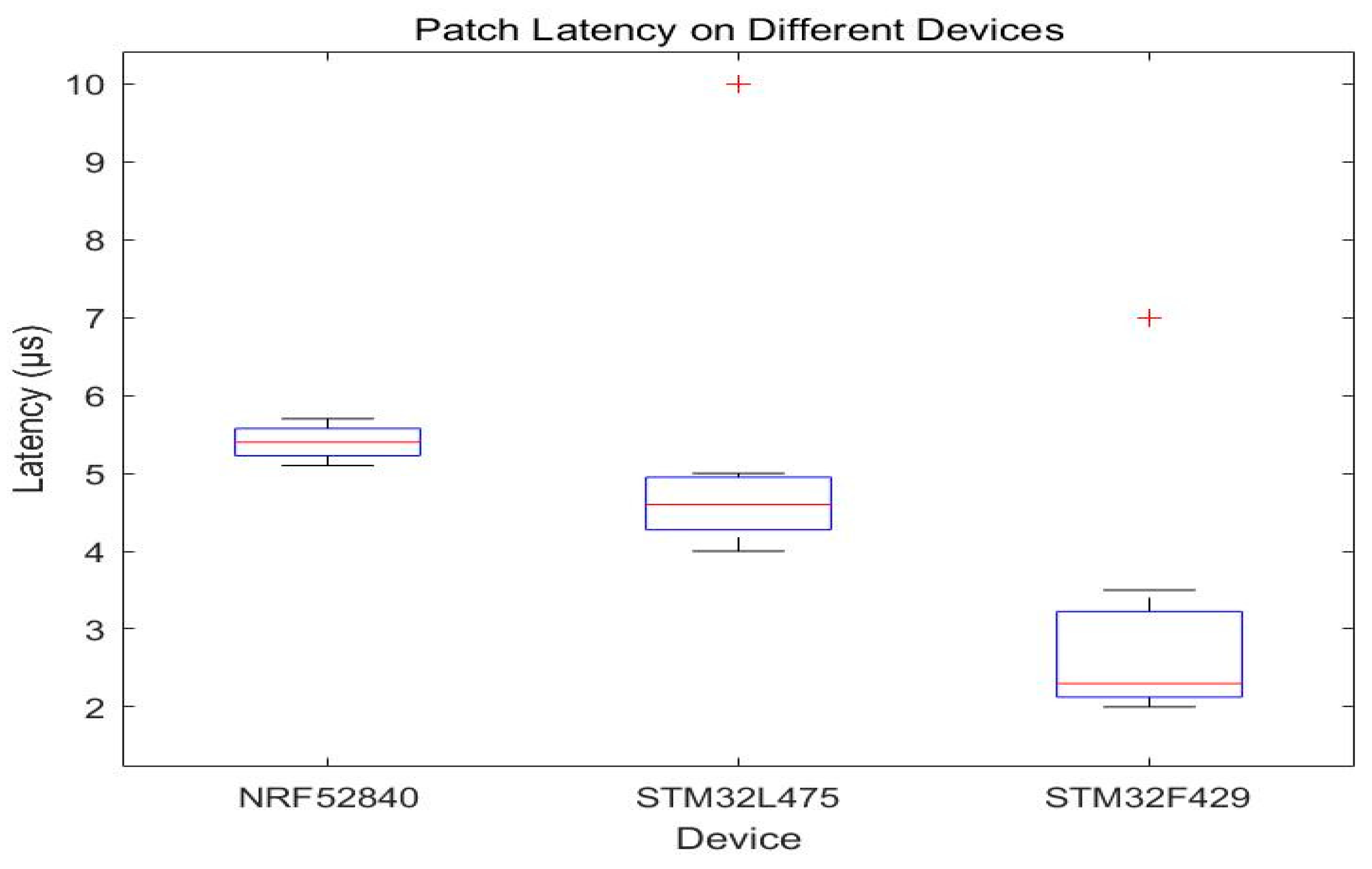
4.3.6. Patch Delay Experiments with Different Devices and Analysis of Results

In order to evaluate the performance of different devices when applying patches, we compared the patch latency of three devices, including NRF52840, STM32L475, and STM32F429, under different operations. The experimental results are shown in Figure 13.
The experimental data show that the latency of NRF52840 is relatively stable under all test conditions, with latency fluctuating between 5.1 μ s and 5.7 μ s , demonstrating better real-time performance. STM32L475 has a latency between 4.0 μ s and 5.0 μ s for the first five tests, with a higher latency (10 μ s ) occurring in the seventh test, suggesting that, in some cases, there can be performance fluctuations. The latency of STM32F429 is below 3 μ s in the first five tests, but it increases significantly in the sixth and seventh tests to 3.5 μ s and 7 μ s , respectively.
Device-level comparisons reveal notable variations in patch latency and consistency, reflecting architecture-dependent performance characteristics. NRF52840 has a more stable latency, making it ideal for latency-sensitive applications. STM32L475 has a lower latency, but performance fluctuations may occur in some cases, which need to be paid attention to in practical applications. STM32F429 has a lower latency in general but increases in longer tests, which must be selected according to specific needs when applying the patches. STM32F429 has a lower latency time overall, but the latency increases in longer tests, so it should be selected according to the specific needs in the application.

4.3.7. Comparison with State-of-the-Art Methods

To assess the effectiveness of the proposed patching mechanism, we compared our method with two state-of-the-art hot-patching frameworks as shown in Table 3:
  • HERA, which targets embedded real-time systems via hardware-assisted patching;
  • RapidPatch, a high-speed eBPF-based hot patch generator for firmware.
All methods were evaluated under consistent hardware and software conditions, where applicable. Since HERA and RapidPatch were not originally designed for the same microcontroller platform, implementation details were adapted using open-source reproductions provided by the authors.
Compared with HERA and RapidPatch, the proposed method achieved a lower fixing latency (15.2 ms vs. 21.4 ms and 42.7 ms, respectively) and a higher patch success rate under constrained environments. While HERA provides hardware-level fast switching, it is tightly coupled with the ARM Cortex-M family [35]. RapidPatch, though flexible in patch generation [36,37], suffers from a higher runtime footprint and a limited deployment scope due to its reliance on eBPF.
Our method maintains platform generality by decoupling patch logic from hardware and achieves runtime efficiency by leveraging the onboard FPB mechanism. This balance between performance, success rate, and portability demonstrated the practical advantage of our approach in embedded hot patch scenarios.

5. Conclusions

Analyzed by the above experimental results, the hot-patching approach has shown obvious advantages in several key indicators. Specifically, hot patching can significantly shorten the vulnerability fixing time while improving the stability and availability of the system. In contrast, the traditional update method may lead to long system downtime and affect normal operation, while unapplied patches may trigger frequent system crashes and service interruptions. Overall, the hot-patching approach has performed well in embedded device vulnerability remediation, effectively reducing system downtime and service interruptions and providing strong support for system stability and availability. The performance differences between dissimilar or asymmetric devices when applying patches have also provided an important reference for choosing appropriate remediation strategies, which will help the optimization of the effect of patch application and overall system performance.
In the future, we will work on scalability with efficiency balancing domains of this patching for embedded devices used in IoT and CPS architectures. We also have a plan to work with embedded devices that are in blockchain-based IIoT and work with symmetric approaches like distributed way.

Author Contributions

Conceptualization, Z.X., B.Z., and A.B.; methodology, Z.X., B.Z., and A.B.; software Z.X., B.Z., A.B., and Y.W.; validation, Z.X., B.Z., A.B., Y.W., and C.H.; formal analysis, Z.X., B.Z., A.B., Y.W., and C.H.; investigation, Z.X., B.Z., A.B., Y.W., and C.H.; resources, Z.X. and B.Z.; data curation, B.Z., A.B., Y.W., and C.H.; writing—original draft preparation, Z.X., B.Z., A.B., Y.W., and C.H.; writing—review and editing, Z.X., B.Z., A.B., Y.W., and C.H.; visualization, B.Z., A.B., Y.W., and C.H.; supervision, B.Z. and A.B.; project administration, B.Z. and A.B.; funding acquisition, B.Z. All authors have read and agreed to the published version of the manuscript.

Funding

This study was supported by the National Key Research and Development Program of China (Project No. 2022YFB3104300).

Data Availability Statement

The original contributions presented in this study are included in the article. Further inquiries can be directed to the corresponding authors.

Conflicts of Interest

The authors Zesheng Xi, Bo Zhang, Yunfan Wang, and Chuan He were employed by the company State Grid Smart Grid Research Institute Co., Ltd. The remaining authors declare that this research was conducted in the absence of any commercial or financial relationships that could be construed as a potential conflict of interest.

References

  1. Bhattacharjya, A.; Kozdroj, K.; Bazydlo, G.; Wisniewski, R. Trusted and Secure Blockchain-Based Architecture for Internet-of-Medical-Things. Electronics 2022, 11, 2560. [Google Scholar] [CrossRef]
  2. Jeong, H.; Baik, J.; Kang, K. Functional level hot-patching platform for executable and linkable format binaries. In Proceedings of the 2017 IEEE International Conference on Systems, Man, and Cybernetics (SMC), Banff, AB, Canada, 5–8 October 2017; pp. 489–494. [Google Scholar]
  3. Bhattacharjya, A.; Zhong, X.; Xing, L. Secure Hybrid RSA (SHRSA) based multilayered authenticated, efficient and End to End secure 6-layered personal messaging communication protocol. In Digital Twin Technologies and Smart Cities, Internet of Things (IoT); Springer Nature: Cham, Switzerland, 2020; Available online: https://www.springer.com/gb/book/9783030187316#aboutBook (accessed on 20 April 2025).
  4. Ziems, N.; Wu, S. Security vulnerability detection using deep learning natural language processing. In Proceedings of the IEEE INFOCOM 2021—IEEE Conference on Computer Communications Workshops (INFOCOM WKSHPS), Vancouver, BC, Canada, 10–13 May 2021; pp. 1–6. [Google Scholar]
  5. Nweke, L.O. A survey of specification-based intrusion detection techniques for cyber-physical systems. Int. J. Adv. Comput. Sci. Appl. 2021, 5. [Google Scholar] [CrossRef]
  6. Cai, W.; Chen, J.; Yu, J.; Gao, L. A software vulnerability detection method based on deep learning with complex network analysis and subgraph partition. Inf. Softw. Technol. 2023, 164, 107328. [Google Scholar] [CrossRef]
  7. Gu, H.; Shang, J.; Wang, P.; Mi, J.; Bhattacharjya, A. A Secure Protocol Authentication Method Based on the Strand Space Model for Blockchain-Based Industrial Internet of Things. Symmetry 2024, 16, 851. [Google Scholar] [CrossRef]
  8. Kumar, J.R.H.; Bhargavramu, N.; Durga, L.S.N.; Nimmagadda, D.; Bhattacharjya, A. Blockchain Based Traceability in Computer Peripherals in Universities Scenarios. In Proceedings of the 2023 3rd International Conference on Electronic and Electrical Engineering and Intelligent System (ICE3IS), Yogyakarta, Indonesia, 9–10 August 2023. [Google Scholar]
  9. Bhattacharjya, A.; Xiaofeng, Z.; Jing, W. An end-to-end user two-way authenticated double encrypted messaging scheme based on hybrid RSA for the future internet architectures. Int. J. Inf. Comput. Secur. 2018, 10, 63–79. [Google Scholar] [CrossRef]
  10. Bhattacharjya, A.; Xiaofeng, Z.; Jing, W.; Xing, L. Hybrid RSA-based highly efficient, reliable and strong personal full mesh networked messaging scheme. Int. J. Inf. Comput. Secur. 2018, 10, 418–436. [Google Scholar] [CrossRef]
  11. Bhattacharjya, A.; Xiaofeng, Z.; Jing, W.; Xing, L. On mapping of address and port using translation. Int. J. Inf. Comput. Secur. 2019, 11, 214–232. [Google Scholar] [CrossRef]
  12. Zhang, Z.; Wang, X.; Hao, Q.; Xu, D.; Wang, J.; Liu, J.; Ma, J.; Zhang, J. Hardware-Implemented Security Processing Unit for Program Execution Monitoring and Instruction Fault Self-Repairing on Embedded Systems. Appl. Sci. 2022, 12, 3584. [Google Scholar] [CrossRef]
  13. Li, Z.; Wang, P.; Wang, Z. FlowGANAnomaly: Flow-based anomaly network intrusion detection with adversarial learning. Chin. J. Electron. 2024, 33, 58–71. [Google Scholar] [CrossRef]
  14. Wang, Z.; Li, Z.; Fu, M.; Ye, Y.; Wang, P. Network traffic classification based on federated semi-supervised learning. J. Syst. Archit. 2024, 149, 103091. [Google Scholar] [CrossRef]
  15. Li, Z.; Zhang, Z.; Fu, M.; Wang, P. A novel network flow feature scaling method based on cloud-edge collaboration. In Proceedings of the 2023 IEEE 22nd International Conference on Trust, Security and Privacy in Computing and Communications (TrustCom), Exeter, UK, 1–3 November 2023; pp. 1947–1953. [Google Scholar]
  16. Niesler, C.; Surminski, S.; Davi, L. HERA: Hotpatching of Embedded Real-time Applications. In Proceedings of the Network and Distributed Systems Security (NDSS) Symposium 2021, Virtual, 21–25 February 2021; pp. 21–25. [Google Scholar]
  17. Li, Z.; Liu, M.; Wang, P.; Su, W.; Chang, T.; Chen, X.; Zhou, X. Multi-ARCL: Multimodal Adaptive Relay-Based Distributed Continual Learning for Encrypted Traffic Classification. J. Parallel Distrib. Comput. 2025, 201, 105083. [Google Scholar] [CrossRef]
  18. Payer, M.; Bluntschli, B.; Gross, T.R. DynSec: On-the-fly Code Rewriting and Repair. In Proceedings of the 5th Workshop on Hot Topics in Software Upgrades (HotSWUp 13), San Jose, CA, USA, 24–28 June 2013. [Google Scholar]
  19. Holmbacka, S.; Lund, W.; Lafond, S.; Lilius, J. Lightweight Framework for Runtime Updating of C-Based Software in Embedded Systems. In Proceedings of the 5th Workshop on Hot Topics in Software Upgrades (HotSWUp 13), San Jose, CA, USA, 24–28 June 2013. [Google Scholar]
  20. Jiang, W.; Liu, L. Research on hot-patching technology based on VXWORKS system. Comput. Technol. Dev. 2017, 27, 18–22+28. [Google Scholar]
  21. Zhou, M.; Wang, H.; Li, K.; Zhu, H.; Sun, L. Save the Bruised Striver: A Reliable Live Patching Framework for Protecting Real-World PLCs. In Proceedings of the EuroSys’24: The Nineteenth European Conference on Computer Systems, Athens, Greece, 22–25 April 2024; pp. 1192–1207. [Google Scholar]
  22. Ye, H.; Gu, J.; Martinez, M.; Durieux, T.; Monperrus, M. Automated classification of overfitting patches with statically extracted code features. IEEE Trans. Softw. Eng. 2021, 48, 2920–2938. [Google Scholar] [CrossRef]
  23. Wang, M. Exploration and application of remote hot deployment based on SpringBoot. Inf. Comput. 2023, 35, 1–4. [Google Scholar]
  24. Xiong, Y.; Liu, X.; Zeng, M.; Zhang, L.; Huang, G. Identifying patch correctness in test-based program repair. In Proceedings of the 40th International Conference on Software Engineering, Gothenburg, Sweden, 27 May–3 June 2018; pp. 789–799. [Google Scholar]
  25. He, Y.; Zou, Z.; Sun, K.; Liu, Z.; Xu, K.; Wang, Q.; Shen, C.; Wang, Z.; Li, Q. RapidPatch: Firmware Hotpatching for Real-Time Embedded Devices. In Proceedings of the 31st USENIX Security Symposium, Boston, MA, USA, 10–12 August 2022; pp. 10–12. [Google Scholar]
  26. Ramaswamy, A.; Bratus, S.; Smith, S.W.; Locasto, M.E. Katana: A Hot Patching Framework for ELF Executables. In Proceedings of the 2010 International Conference on Availability, Reliability and Security, Krakow, Poland, 15–18 February 2010; pp. 507–512. [Google Scholar]
  27. Naeem, H.; Alsirhani, A.; Alserhani, F.M.; Ullah, F.; Krejcar, O. Augmenting Internet of Medical Things Security: Deep ensemble integration and methodological fusion. Comput. Model. Eng. Sci. 2024, 141, 2185–2223. [Google Scholar] [CrossRef]
  28. Chen, H.; Chen, R.; Zhang, F.; Zang, B.; Yew, P.-C. Live updating operating systems using virtualization. In Proceedings of the VEE06: Second International Conference on Virtual Execution Environments, Ottawa, ON, Canada, 14–16 June 2006. [Google Scholar]
  29. Altekar, G.; Bagrak, I.; Burstein, P.; Schultz, A. OPUS: Online Patches and Updates for Security. In Proceedings of the 14th USENIX Security Symposium, Baltimore, MD, USA, 31 July–5 August 2005. [Google Scholar]
  30. Zhu, Z.; Chen, H.; Zhang, J.; Wang, X.; Jin, Z.; Xue, M.; Zhu, D.; Choo, K.K.R. MFABA: A More Faithful and Accelerated Boundary-Based Attribution Method for Deep Neural Networks. In Proceedings of the Thirty-Eighth AAAI Conference on Artificial Intelligence, Vancouver, BC, Canada, 20–27 February 2024; Volume 38, pp. 17228–17236. [Google Scholar]
  31. Zhang, J.; Ling, X.; Wang, Y. Design of a generic framework for assembly engineering for ARM Cortex-M series cores. Small Microcomput. Syst. 2021, 42, 2440–2445. [Google Scholar]
  32. Mao, Y.; Migliore, V.; Nicomette, V. MATANA: A Reconfigurable Framework for Runtime Attack Detection Based on the Analysis of Microarchitectural Signals. Appl. Sci. 2022, 12, 1452. [Google Scholar] [CrossRef]
  33. Zhu, Z.; Jin, Z.; Wang, X.; Zhang, J.; Chen, H.; Choo, K.-K.R. Rethinking Transferable Adversarial Attacks with Double Adversarial Neuron Attribution. IEEE Trans. Artif. Intell. 2024, 6, 354–364. [Google Scholar] [CrossRef]
  34. Dong, Y.; Guo, W.; Chen, Y.; Zhang, Y.; Wang, G. Towards the Detection of Inconsistencies in Public Security Vulnerability Reports. In Proceedings of the 28th USENIX Security Symposium, Santa Clara, CA, USA, 14–16 August 2019. [Google Scholar]
  35. Shi, J.; Wang, Y.; Su, Y.; Chen, S. Analysis of MQX interrupt mechanism and interrupt program framework design based on ARM Cortex-M4. Comput. Sci. 2013, 40, 41–44. [Google Scholar]
  36. Zhou, C. Design and Implementation of Server/Client Based Patch Management System. Microcomput. Appl. 2009, 30, 53–57. [Google Scholar]
  37. Correa, R.; Bermejo Higuera, J.R.; Higuera, J.B.; Sicilia Montalvo, J.A.; Rubio, M.S.; Magreñán, Á.A. Hybrid security assessment methodology for web applications. Comput. Model. Eng. Sci. 2021, 126, 89–124. [Google Scholar]
Figure 1. Flowchart showing the process of inserting jump instruction through the debugging unit.
Symmetry 17 00983 g001
Figure 2. Impact of patch size and vulnerability complexity on patch injection accuracy.
Symmetry 17 00983 g002
Figure 3. Overall patch-switching workflow using the debug unit.
Symmetry 17 00983 g003
Figure 4. Comparison of vulnerability fixing time.
Symmetry 17 00983 g004
Figure 5. Mean and standard deviation of fixing time across methods.
Symmetry 17 00983 g005
Figure 6. Comparison of the vulnerability fixing success rate.
Symmetry 17 00983 g006
Figure 7. Statistical summary of vulnerability fixing success rates.
Symmetry 17 00983 g007
Figure 8. System stability comparison chart.
Symmetry 17 00983 g008
Figure 9. Statistical summary of system stability.
Symmetry 17 00983 g009
Figure 10. System availability comparison chart.
Symmetry 17 00983 g010
Figure 11. Comparison of CPU cycles required for different patch-triggering methods.
Symmetry 17 00983 g011
Figure 12. Comparison of the time required for different patch-triggering methods.
Symmetry 17 00983 g012
Figure 13. Patch latency on different devices.
Symmetry 17 00983 g013
Table 1. Environment configurations.
CategoriesNameDescription
HardwareMultiprocessorIntel Core i7-10870H
GPUsNVIDIA GeForce RTX 3060
Random access memory (RAM)16 GB DDR4
SoftwareDevelopment and operating environmentsUbuntu 20.04 LTS
Integrated development environment (IDE)Eclipse IDE 2021-09
Programming languageC, C++
Debugging Tools versionGDB 10.1 Git 2.25.1
Control network toolWireshark 3.4.8
Traffic ToolsScapy 2.4.5
Virtualized environmentVMware Workstation Pro
Table 2. Datasets.
Table 2. Datasets.
Vulnerability IDSubassembliesDescription(Machine) Filter
2020-17441PicoTCPValidate lPv6 payload length field against actual size for function pico ipv6 processp!ValidateFilter Patch
2020-17442PicoTCPHop-by-hop lPv6 extension header length field for functionFilter Patch
2020-17443PicoTCPpico ipv6 process restricts that echo->transport len is no less than 8 inpico_icmp6_send.echoreplyFilter Patch
2020-17444PicoTCPCheck possible overflow of header extension length field forpico_ipv6_check headers._.sequenceFilter Patch
2020-17445PicoTCPValidate optlen using a loop prior to function pico ipv6_process_destoptFilter Patch
Table 3. Comparative evaluation of hot-patching methods.
MethodFixing Time (ms)Success Rate (%)Memory Overhead (KB)Platform Dependency
HERA21.495.25.6Cortex-M only
RapidPatch 42.797.48.1x86/eBPF Required
Proposed method15.298.73.1Generic (ARMv7-M)
Disclaimer/Publisher’s Note: The statements, opinions and data contained in all publications are solely those of the individual author(s) and contributor(s) and not of MDPI and/or the editor(s). MDPI and/or the editor(s) disclaim responsibility for any injury to people or property resulting from any ideas, methods, instructions or products referred to in the content.

